Article

Effects of Snake-Bioinspired Surface Texture on the Finger-Sealing Performance under Varied Working Conditions

1
School of Mechanical and Precision Instrumental Engineering, Xi’an University of Technology, Xi’an 710048, China
2
School of Mechanical Engineering, Hunan Institute of Engineering, Xiangtan 411104, China
3
Department of Mechanical and Aerospace Engineering, Brunel University London, London UB8 3PN, UK
*
Author to whom correspondence should be addressed.
Machines 2022, 10(7), 569; https://doi.org/10.3390/machines10070569
Submission received: 1 June 2022 / Revised: 7 July 2022 / Accepted: 11 July 2022 / Published: 15 July 2022

Abstract

:
The tribological performance of the friction pair between the rotor and finger feet is a crucial index affecting the service life of finger seals. In recent years, the surface texture has attracted a considerable number of researchers owing to its extraordinary potential in improving antifriction and wear resistance. This paper, inspired by snakeskins, introduces three texture forms (e.g., diamond, ellipse, and hexagon) into the rotor. The effects on finger-sealing performance are analyzed by considering finger seals’ varied working conditions. First, a numerical model of textured finger seals under hydrodynamic lubrication is established based on the Reynolds equation. Then, the sealing performance analysis of textured finger seals is performed considering varied working conditions given rotation speed, pressure difference, seal clearance, and working temperature. The numerical results show that: (1) the textured domain produces a noticeable hydrodynamic pressure effect and cavitation, which effectively improves the bearing capacity of the fluid film; (2) the higher the rotation speed or the lower the inlet/outlet pressure difference, the stronger the dynamic pressure effect of textured finger seals and the better the antifriction and wear resistance; (3) for good antifriction and wear resistance of a textured finger seal, the seal clearance should be as shallow as possible (≤10 μm), and the working temperature should be as low as possible (≤120 °C); and (4) the ellipse texture has a higher average dimensionless pressure and a lower friction coefficient, which is superior to diamond and hexagon ones in terms of friction and wear performance.

1. Introduction

As a new type of compliant seal developed following brush seals, finger seals are justifiably famous for their low leakage rate and long service life [1]. They have broad application prospects in aero-engine and gas turbine fields [2]. Finger seals are usually operated under severe working conditions, specifically, i.e., high-temperature, high-pressure difference, high-rotational speed, and wide temperature range. With the continuous development of aero-engine technology, new challenges are put forward to finger seals such as their adaptability and dynamic sealing performance under varied working conditions (e.g., in the process of take-off, climbing, cruising, and landing, the variation range of aero-engine rotation speed and the pressure difference between the inlet and outlet is 0~30000 rpm, and 0.1~1 MPa, respectively). Currently, the service life of seals in critical parts of aero-engines requires more than 4000 h, whereas the current working life of finger seals is only 500~1000 h. Therefore, it is of great significance to develop the dynamic sealing technology of finger seals under complex operating conditions.
The tribological performance of the friction pair between the rotor and finger feet is a crucial index affecting the service life of finger seals [3]. Until recently, ways to improve the friction and wear performance of finger seals were primarily based on new structures [4], new materials [5], and coatings [6,7]. However, the above methods are not satisfactory enough for improving the friction dynamics performance. In other words, there is still a gap to fill by exploring new techniques. Recently, some scholars observed and studied the surface morphology of earthworms [8], pangolins [9], snakes [10], fishes [11], snails [12], and other organisms, and found that these surface morphologies usually have good properties of desorption, anti-adhesion and wear resistance [13]. Inspired by the biological surface morphologies, the non-smooth surface has been successfully applied to multiple occasions with relative motion, e.g., bearings [14], cylinder liners [15], mechanical seals [16], and cutting tools [17], to improve the tribological properties [18].
According to the lubrication state, the main functions of surface textures to improve tribological properties can be divided into several categories, as follows. (1) Under dry friction, acting as traps to collect wear debris and reduce abrasive wear. In addition, changing the contact stress distribution and reducing the direct contact between the interface to reduce friction and wear [19]. (2) Under boundary to mixed lubrication, acting as micro-reservoirs and generating a large number of micro-fluidic film bearings to enhance the lubrication of the frictional substrate [20]. (3) Under hydrodynamic lubrication, generating hydrodynamic pressure to improve the load-carrying capacity [21]. The tribological characteristics of finger seals in the start–stop phase belong to dry friction or boundary lubrication and can be regarded as hydrodynamic lubrication when running smoothly. As mentioned before, surface engineering is advanced in natural surface construction, especially in legless reptiles, such as snakes. Snakes live in highly harsh and complex environments, and their skins have evolved over millions of years to control friction or reduce hydrodynamic and aerodynamic drag, thus improving their maneuverability when crawling, swimming, and even flying [22,23]. Because of this, the engineering application of snakeskin-inspired surface textures has attracted a great deal of research in recent decades [24]. Cuervo et al. [25] machined a series of elliptical textures on the surface of titanium alloy (Ti6Al4V) pins with an arrangement derived from the geometric pattern observed in the ventral scales of a royal python. The experimental results showed that the elliptical textured pins obtained a lower surface friction coefficient than that of the non-textured pins, which is beneficial to reduce frictional wear. Inspired by the characteristics of the Vipera Ammodytes snakeskins, Sánchez et al. [26] processed a series of elliptical textures on the surface of AISI 52100 steel by photochemical processing technology and carried out sliding friction tests. The experimental results show that the textured surface reduces the friction coefficient, and the tribological properties are increased by 30%. Based on the ventral scale dimensions of a ball python, Bapat et al. [27] used a laser powder bed fusion process to fabricate hexagonal textures with different hierarchical designs and conducted guided traction friction tests. The results showed that the relative orientation of the micro-textures determined the vibration and anisotropic friction. This study provides guidance for the design of anti-slip for components such as mechanical fixtures.
Motivated by the snake-bioinspired texture effectively improving the tribological properties of the friction interface, the authors proposed four snake-bioinspired textures (e.g., diamond, ellipse, hexagon, and triangle) for finger seals. They evaluated the influence of the arrangements and parameters of surface textures on finger-sealing performance [28]. The results have shown that it can significantly improve the sealing performance at the texture density of 20~40%, the texture depth of 5~25 μm, and the texture arrangement consistent with the rotation direction of the rotor. As a further study of the previous work, this paper explores the impact of surface textures on the performance improvement of finger seals under varied working conditions. First, inspired by snakeskins, three textures are selected by a friction simulation of the textured finger seal combining the practical application condition with the principle of a similar PV value (P, V represent pressure and velocity). Secondly, a detailed numerical model is established based on the Reynolds equation. The sealing performance is analyzed considering the impact of working conditions (i.e., rotation speed, pressure difference, seal clearance, and working temperature) on the textured finger seal. Thirdly, numerical analysis results are presented and discussed, and finally, conclusions are listed.

2. Materials and Methods

As mentioned above, the tribological characteristics of finger seals can be regarded as dry friction and hydrodynamic lubrication during the start–stop phase and smooth operation, respectively. In this section, the authors first introduce the geometrical model of finger seal, then select three types of snake-bioinspired surface textures by friction simulation under dry friction, and finally, derive a numerical model based on the Reynolds equation under hydrodynamic lubrication.

2.1. Geometrical Model

2.1.1. Finger Seal

As shown in Figure 1a, the main components of the finger seal include the front plate, front spacer, finger laminates (3~5 layers, and the thickness of each layer is about 0.2 mm), and back plate. As the primary parts of finger seals, each finger laminate is processed into a group of evenly distributed finger curved beams ending with finger feet in the circumferential direction (see Figure 1b). Figure 1c shows the main dimensions of the finger seal. A range of surface textures is evenly distributed on the rotor’s circumferential surface to improve the friction pair’s tribological properties between the rotor and finger feet.

2.1.2. Surface Textures

As described in Section 1, bioinspired surface textures possess significant potential for improving tribological properties. Therefore, combined with the working condition of finger seals and the living environments of snakes, snake-bioinspired surface textures are adopted in this paper for finger seals. Four common forms of snakeskins, i.e., ellipse (E), diamond (D), hexagon (H), and triangle (T), are selected and evenly arranged on the rotor, respectively (the single texture area is 10,000 μm2), as listed in Table 1.
As the finger feet are in direct contact with the rotor, as shown in Figure 1c, there is an inevitable phenomenon of friction and wear between them. In this section, friction simulation between the textured rotor and the finger feet is carried out according to the actual working condition to explore the influence of the surface texture forms on the equivalent stress distribution of the friction pair and further select the surface texture forms in finger seal. For more efficiency, the finite element model is properly simplified as follows: the finger feet and the rotor are taken straight, and the finger feet are simplified as an upper slider (the dimensions are 1 × 1 × 0.5 mm (X, Y, Z), where the dimension in the X direction indicates the thickness of the finger laminates); the rotor is simplified as a bottom slider (the dimensions are 1 × 2 × 0.5 mm (X, Y, Z), where the dimension in the X direction represents the contact width between the textured rotor and the finger feet), as shown in Figure 2a.
Static structural analysis of the finger seal is carried out first to obtain the average contact pressure between the rotor and the finger feet. The specific modeling and analysis process can be referred to [29]. According to the principle of a similar PV value, the pressure and velocity in the friction simulation are given, as shown in Table 2. The average contact pressure between the finger feet and the rotor in dynamic simulation is calculated to be 0.29 MPa (pressure difference of 0.3 MPa). According to the rotating speed of 6000 r/min and the rotor radius of 40 mm, the linear speed is 25.103 m/s, and the PV value is 7.28 (0.29 × 25.103 = 7.28). Combined with the principle of PV similarity, the pressure and velocity in the friction simulation of this paper are set to be 7.28 MPa and 1 m/s respectively.
The friction simulation results in Figure 2b show that the maximum stress values of the triangle texture are the largest (the values of the upper and bottom sliders are 21.29 MPa and 30.9 MPa, respectively), whereas the values of the diamond, ellipse, and hexagon textures are relatively smaller. The results of the upper and bottom sliders are given 60% and 40% weights, respectively, for comprehensive evaluation. The comprehensive maximum stress value of the ellipse texture is the lowest (15.21 MPa), followed by diamond (15.42 MPa) and hexagon (16.14 MPa), and the triangle is the largest (23.12 MPa). Therefore, the ellipse, diamond, and hexagon textures with lower comprehensive maximum stress are selected in this paper.

2.2. Mathematical Model

Generally, the assembly process between the rotor and the finger feet is transition fit. In the process of rotation, the rotor exerts a radial excitation on the finger feet. A concomitant hysteretic effect follows, owing to the good flexibility of the finger beam. Thereby, a thin fluid film (≤20 μm) is formed between the rotor and the finger feet when running smoothly. The fluid film can effectively avoid the direct contact of the friction pair, greatly reduce the friction and wear, and improve the service reliability and durability of the finger seal. So, the tribological properties between them can be considered as hydrodynamic lubrication. Regarding the mathematical modeling of surface textures, there are still some debates in the literature. Some prefer the Reynolds equation due to its good conformity between theoretical analysis and experimental tests [30,31,32], whereas others recommend the more accurate N-S equation [33,34,35] due to consideration of the fluid inertial term. By referring to the study of the application scope of the Reynolds equation in surface texture theoretical modeling [36], it has been shown that the influence of the inertia term can be ignored when the clearance ratio L/h ≥ 46 (h is the film thickness, and L is the typical length of friction pair), in which case the Reynolds equation can replace the N-S equation for numerical analysis, but with consideration of the effect of the cavitation phenomenon on pressure distribution.
Given that the thickness of a single finger laminate is 0.2~0.3 mm in this paper (see Figure 1c), the total thickness of five-layer finger laminates is more than 1 mm (L ≥ 1 mm), and the seal clearance of the contact type finger seal is less than 20 μm (h ≤ 20 μm). So, L/h ≥ 50, the o(Reδ2) ≪ 1, and the Reynolds equation is adopted to elaborate a mathematical model in this paper.
Based on the Reynolds equation, the authors have derived a mathematical model of surface textured finger seal under hydrodynamic lubrication to study the impact of surface texture parameters on the sealing performance [28]. Based on this, the state equation considering the viscosity-temperature effect is derived in the following sections to further explore the effects of surface textures on sealing performance under varied working conditions.

2.2.1. Modelling Assumption

The mathematical model assumptions are as follows:
A1.
The inertial force (e.g., centrifugal pull) and volume force (e.g., gravity) are neglected.
A2.
The fluid slip of the friction interface is neglected.
A3.
No deformation of the finger seal and rotor exists.
A4.
The pressure variation along the film thickness is neglected.
A5.
The effects of surface roughness of the rotor and finger seal are neglected.
A6.
The variations of viscosity and temperature in the flow field are neglected.
Based on the descriptions and assumptions above, the sketch of the textured finger seal is presented as shown in Figure 3, and the parameters are listed in Nomenclature. It is worth noting that the rotating motion between the rotor and the finger feet is replaced by a plane motion to facilitate the mathematical modeling, as shown in Figure 3b. The initial condition is that a uniform pressure, p, is applied at the inlet boundary, and the outlet boundary pressure is set to 0 MPa. The length and width of the rotor are xr and yr, respectively, where the length xr is the contact width between the rotor and the finger feet. The seal clearance and the texture depth are hc and ht, respectively.

2.2.2. Control Equation

Under hydrodynamic lubrication, the steady-state pressure control equation of textured finger seal can be written as
x ( h 3 η p x ) + y ( h 3 η p y ) = 6 x ( U h )
where x and y are the horizontal and longitudinal coordinates, respectively, p is the pressure of fluid film, η is the hydrodynamic viscosity, h is the local film thickness, and U is the sum of linear velocities of the upper and lower interfaces. Due to the surface texture, the local fluid film thickness varies regularly and orderly, and it can be written as below:
h ( x , y ) = { h c + h t ( x , y Ω t ) h c ( x , y Ω t ) ,
where Ω t represents the region with surface textures.
The dimensionless form of Equation (1) is written as below:
X ( H 3 P X ) + Y ( H 3 P Y ) = Λ H X ,
where Λ = 6 U η x r h c 2 p I is the working condition parameter of the finger seal, X and Y are the dimensionless horizontal and longitudinal coordinates, respectively. P and H are dimensionless pressure and thickness of the fluid film, respectively.

2.2.3. State Equation

The hydrodynamic viscosity changes with the variation of working temperature. By considering the large temperature difference and sharp conversion in the operating environment of aircraft, the Reynolds viscosity–temperature equation is introduced in this paper as follows:
η = η 0 e β ( T - T 0 ) ,
where, η0, η are the hydrodynamic viscosities at temperatures of T0, and T, respectively, and β is the viscosity–temperature coefficient with a value of 0.03/°C.
The performance parameters of aviation lubricating oil #4050 are adopted in this paper to obtain the hydrodynamic viscosity at different Ts. When the T0 is 40 °C, the η0 is 0.02478 pa·s (the kinematic viscosity and the density are 25.51 × 10⁻⁶ m2/s and 0.9712 × 10³ kg/m3 respectively). The hydrodynamic viscosity at different temperatures can be obtained by substituting the above two values into the viscosity–temperature Equation (4).

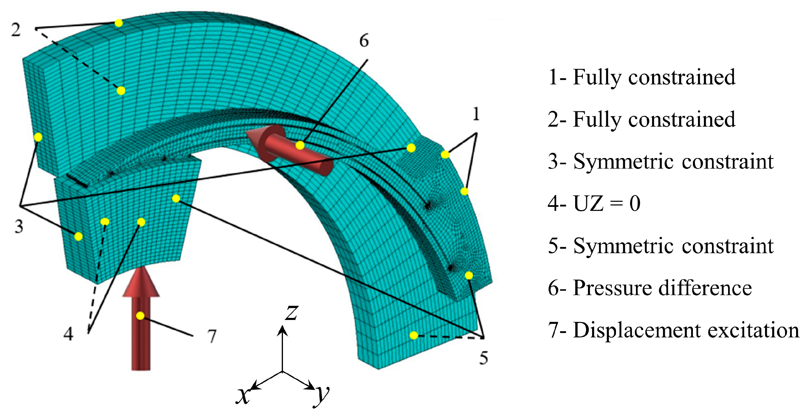
2.2.4. Boundary Conditions

  • Compulsory boundaries.
As illustrated in Figure 3b, the compulsory boundaries can be presented as:
{ p ( x = 0 , y ) = p I p ( x = x r , y ) = p O
where pI and pO are the inlet pressure and outlet pressure, respectively.
2.
Periodic boundaries.
Considering the symmetry of the rotor and the finger seal, it is necessary to ensure that the pressure gradient along the Y-axis is equal in the whole calculation domain, and the upper and lower boundary pressures are equal, too, as illustrated in Figure 3b. Therefore, the periodic boundaries can be presented as:
{ p ( x , y = 1 2 y r ) = p ( x , y = 1 2 y r ) p y ( x , y = 1 2 y r ) = p y ( x , y = 1 2 y r ) = 0 .
3.
Cavitation boundaries.
As described previously, when establishing the hydrodynamic lubrication model based on the Reynolds equation, the influence of the cavitation phenomenon on pressure distribution should be taken into account. Reynolds cavitation boundaries [37] are adopted in this paper and can be presented as:
p c = p a ,   p x = p y = 0 ( x , y ) Ω c ,
where pc and pa are the cavitation pressure and the ambient pressure respectively and Ω c is the cavitation area.

2.2.5. Sealing Performance Parameters

The sealing performance parameters (e.g., bearing force, friction force, and friction coefficient) can be obtained by the relevant calculation of the fluid film pressure (p).
Bearing force (W) can be calculated by integrating p(x,y) over the entire fluid domain as follows:
W = p ( x , y )   d x d y .
Friction force (F) on the surfaces of the finger feet and rotor can be presented as follows:
{ F h = 0 x r 0 y r ( h 2 p x U 0 η h )   d x d y F 0 = 0 x r 0 y r ( h 2 p x U 0 η h )   d x d y ,
where U0 is the surface velocity of the rotor.
Friction coefficient (μ) can be obtained by calculated bearing and friction forces as follows:
μ = F W .

2.3. Numerical Solution

In this article, the Reynolds equation is transformed into a series of linear equations by the finite-difference method, and these corresponding equations are solved by the successive overrelaxation (SOR) iterative method [38]. The iterative procedure of the SOR works as follows:
P k + 1 ( i , j ) = P k ( i , j ) + α ( P k + 1 ( i , j ) P k ( i , j ) ) ,
where k is the number of iterations and α is the relaxation factor.
The convergence precision is calculated as
i = 1 m j = 1 n | P k + 1 ( i , j ) P k ( i , j ) | i = 1 m j = 1 n | P k + 1 ( i , j ) | E r r p ,
where Errp is the error limit.
Before the formal calculation, α and Errp are calculated trial-wise to satisfy the requirements in terms of both efficiency and accuracy. According to the trial calculation results, α and Errp are set as 1.9 and 10−5 respectively [28].

2.4. Calculation Parameters and Working Condition Settings

In the process of take-off, climbing, cruising, and landing, the variation range of aero-engine rotation speed and pressure difference is 0~30,000 rpm and 0.1~1 MPa, respectively. Moreover, aircraft need to pass through the troposphere and stratosphere of different temperatures during take-off and landing. For military aircraft, especially fighters, it is also required to be able to start at extremely low temperatures (−40 °C). Furthermore, it is generally believed that when the aircraft cruising speed is 306 m/s (0.9 Mach), the maximum temperature of aero-engine lubricating oil can reach 204 °C [39]. By considering these actual working conditions with the aforementioned descriptions, the calculation parameters and working conditions are shown in Table 3.

3. Results and Discussion

Based on the mathematical model and boundary conditions in Section 2, this section analyzes the effect of surface textures on the finger sealing performance under varied working conditions, i.e., rotation speed (ω), pressure difference (pI), seal clearance (hc), and working temperature (T). There is no doubt that the leakage and the friction and wear have a significant impact on the stability and effectiveness of the finger seal. In the case of hydrodynamic lubrication, a thinner fluid film produces a larger hydrodynamic bearing force. The larger film-bearing force can effectively lift the finger feet to obtain a non-contact state and effectively reduce the friction and wear; while the thinner fluid film corresponds to the smaller leakage channel, so the leakage rate is reduced. Therefore, this section focuses on the following parameters to measure finger sealing performance: dimensionless pressure (Pav), bearing force (W), friction coefficient (μ), and friction force (F). The first two parameters correspond to the leakage rate of the finger seal and the bearing capacity of fluid film, and the last two parameters correspond to the friction and wear of the finger seal. More information on the parameters is available in Nomenclature.

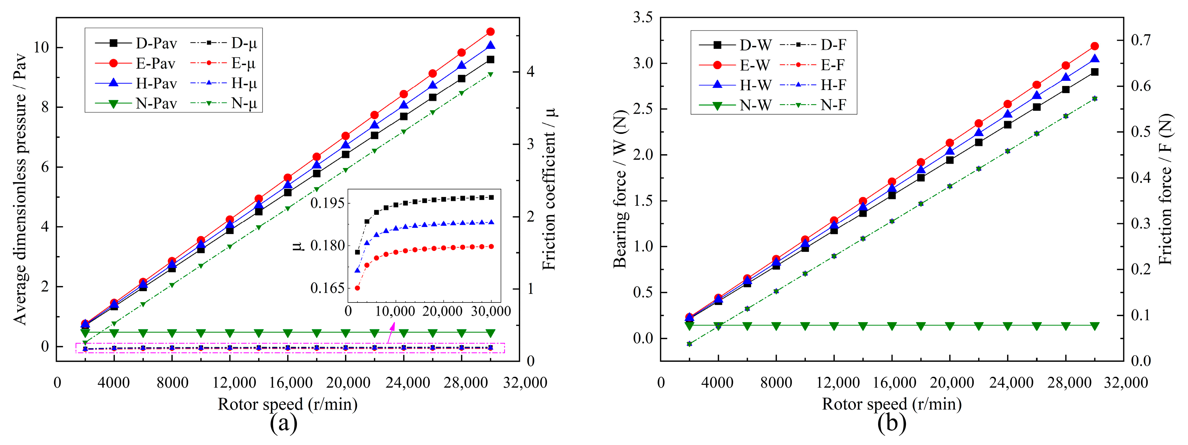
3.1. Effect of the Rotation Speed

Figure 4 shows the dimensionless pressure (P) contour distribution of the three textured finger seals and the non-textured finger seal at the rotation speed (ω) of 20,000 rpm, the pressure difference of 0.3 MPa, seal clearance of 5 μm, and hydrodynamic viscosity of 0.0228 Pa·s. Compared with non-texture, the P of the three textures is significantly increased (the maximum P of ellipse is 18 times that of non-texture, and hexagon and diamond is 16 times that of non-texture). In addition, the dimensionless pressure distribution in the calculation domain without texture decreases gradually from the inlet to the outlet (see Figure 4d). However, there are significant hydrodynamic effects and cavitation in the textured computing domain, and a set of dimensionless pressure peaks and valleys appears in each micro-texture unit (see Figure 4a–c). The reasons for these phenomena are as follows: from the formation mechanism of hydrodynamic pressure, it is well known that the fluid usually produces positive pressure when flowing along the convergent gap, but generally does not produce positive pressure when along the divergent gap. The role of surface texture is to provide regular and orderly convergent gaps and divergent gaps for the fluid flow. The fluid pressure increases at the convergent gap to form a pressure peak and decreases at the divergent gap to form a pressure valley (in particular, cavitation occurs when the pressure decreases to a certain value). It is worth noting that in Figure 4a–c, the pressure peak of the top row texture is smaller than that of four rows below (especially diamond and ellipse). This is because the periodic boundaries are set to ensure that the pressure gradient along the Y-axis is equal and the pressure values of the upper and lower boundaries are equal (Section 2.2.4). Therefore, the pressure peak of the top row texture is smaller than that of other rows.
Figure 5 shows the change of sealing performance parameters in terms of average dimensionless pressure (Pav), friction coefficient (μ), bearing force (W), and friction force (F) when the ω changes from 3000 rpm to 30,000 rpm. It is noted that D-Pav, E-Pav, H-Pav, and N-Pav refer to the average dimensionless pressure of diamond texture, ellipse texture, hexagon texture, and non-texture respectively, and so on for other legends. In the case of non-texture, as shown in Figure 5a, the μ (i.e., N-μ) increases linearly as the ω increases, whereas the Pav (i.e., N-Pav) remains the same. It can be noted that: (1) the increase of ω does not change the pressure distribution; and (2) based on the definition of hydrodynamic viscosity (i.e., the ratio of viscous shear stress to fluid velocity gradient) and the assumption A6 (i.e., the variations of hydrodynamic viscosity is ignored), the increase of ω leads to the increase of velocity gradient along the Z-direction and correspondingly the shear stress, which results in the phenomenon of the internal F (i.e., N-F) and μ (i.e., N-μ) proportional to ω while the Pav (i.e., N-Pav) and W (i.e., N-W) constant.
In contrast to the case without texture, with the increase of ω, the μ of three textures (i.e., D-μ, E-μ, and H-μ) increases slightly and then converges (see the zoom-in view in Figure 5a), whereas the Pav (i.e., D-Pav, E-Pav, and H-Pav) increases linearly and sharply. It shows that: (1) the pressure distribution in three textured calculation domains is changed obviously, the hydrodynamic pressure effect is produced and the bearing capability of the fluid film is improved significantly; (2) although the increase of ω leads to a linear increase of F (see Figure 5b), due to the regular convergence gap generated by the textures; the higher the ω, the stronger the hydrodynamic pressure effect and the larger the fluid film bearing capacity, which results in only slightly changed μ, as shown in Figure 5a. (3) The textured finger seals perform better sealing characteristics than the non-textured counterparts, e.g., at the ω of 20,000 rpm, the values of N-Pav and N-μ are 0.478 and 2.649 respectively, whereas the H-Pav and H-μ are 6.723 (14.065 times of N-Pav) and 0.188 (only 7.097% of N-μ) respectively. (4) Compared with hexagon and diamond textures, the ellipse is calculated with larger P and smaller μ. The smaller friction coefficient is an indicator of good tribological characteristics. In addition, the larger hydrodynamic pressure can better lift the finger feet to avoid direct contact between the finger feet and the rotor, thus reducing friction and wear. Therefore, the ellipse texture possesses better anti-friction and wear resistance. (5) In Figure 5b, the friction curves of three textures and non-texture coincide. The reason is that according to the definition of shear stress (i.e., friction force per unit area), it is proportional to the fluid dynamic viscosity and the velocity gradient along with the film thickness. Under the same working conditions, the dynamic viscosity and velocity gradient of the three textures and non-texture are consistent, which results in the coincidence of the four friction curves.

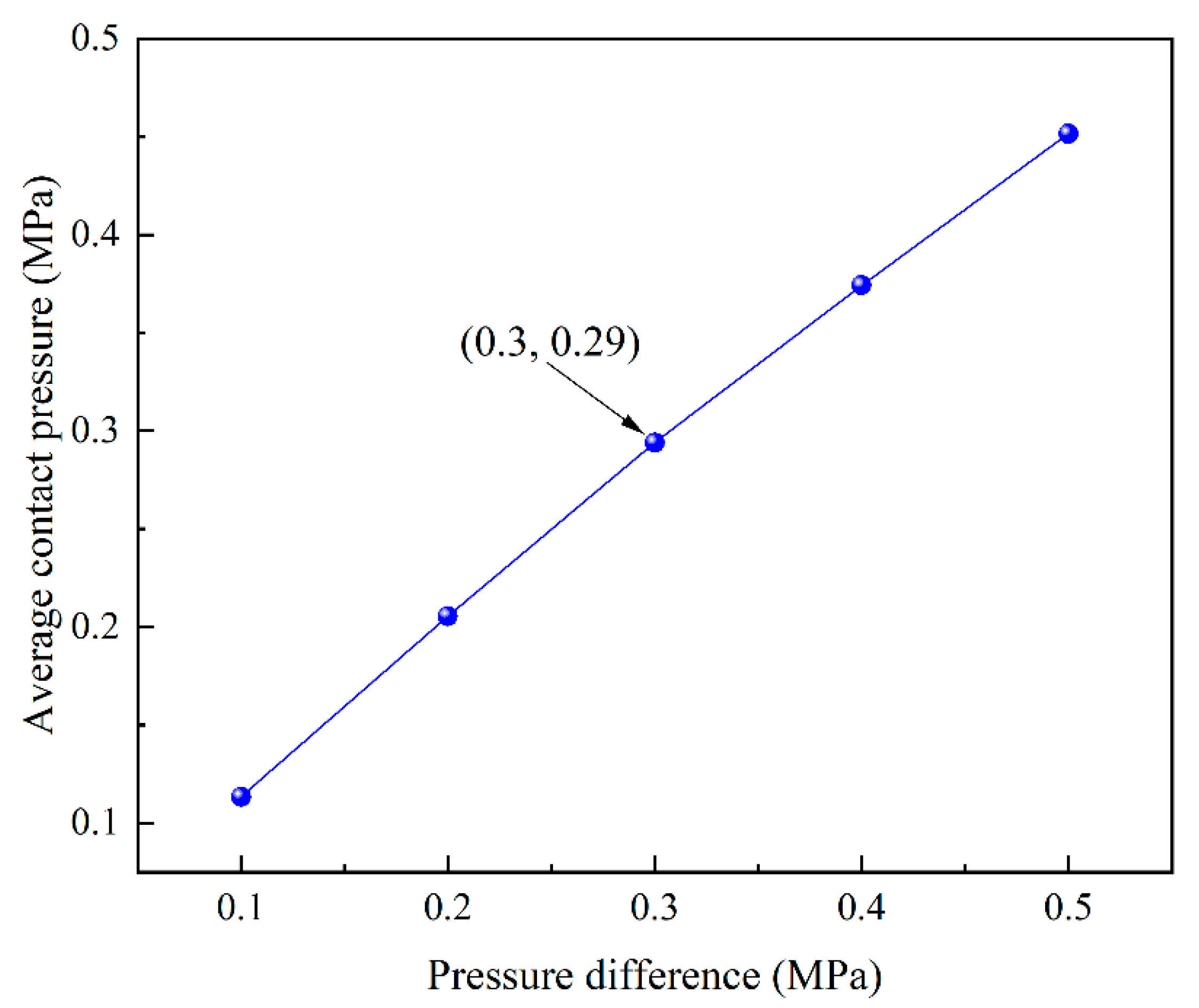
3.2. Effect of the Pressure Difference

Figure 6 shows the Pav and μ of the three textured finger seals and the non-textured finger seal with various pressure differences (i.e., pI in this paper) at rotation speeds of 20,000 rpm and 5000 rpm, seal clearance of 5 μm, and hydrodynamic viscosity of 0.0228 Pa·s. In the case of non-texture, with the increase of pI, the N-μ first decreases sharply and then converges, whereas the N-Pav remains constant. This shows that (1) the change of pressure distribution in the calculation domain of the non-texture is proportional to the change of pI; and (2) according to Section 3.1, the F is proportional to rotation speed, as the rotation speed is constant. Hence the N-F is also a certain value, whereas, with the increase of pI, the pressure and the N-W in the calculation domain increase greatly at first, resulting in the rapid reduction of the N-μ. In addition, with the further increase of pI, the fluid medium leakage becomes larger, resulting in the gradual convergence of the N-μ.
On the contrary, with the increase of pI, the μ of three textures almost remains the same whereas the Pav first decreases sharply and then gradually flattens. The reasons are as follows: (1) the surface textures supply regular and orderly convergence gaps, which helps to produce a hydrodynamic pressure effect. As the fluid flows through the texture area, the violent hydrodynamic pressure effect is produced, which greatly improves the bearing capacity of the fluid film. According to the definition of P (i.e., the ratio of film pressure to inlet pressure), with the increase of pI, the P and Pav of the three textured finger seals decreases rapidly at first. (2) With the further increase of pI, the Pav gradually flattens for the following reasons. On the one hand, the pressure enhancement in the calculation domain is slowed down due to the larger leakage of the fluid medium. On the other hand, according to the definition of P, the increasing trend of pI in denominator gradually slows down. (3) As the F and W of the three textured finger seal remain almost unchanged, the value of μ changes little.
In addition, comparing the Pav and the μ under two different rotation speeds in Figure 6, shows that (1) the higher the rotation speed, the higher the corresponding Pav and μ (except for the N-Pav with a certain value of 0.478), and the better sealing performance of the textured finger seal; (2) in case of low-pressure difference (i.e., pI ≤ 1 MPa), the textured finger seals perform better-sealing performance than the non-textured counterparts, whereas high-pressure difference (i.e., pI > 1 MPa), the corresponding parameter curves of textured and non-textured finger seals tend to be equal as the pI increases; and (3) at the rotation speed of 5000 rpm and the pI of 1.5 MPa, the values of D-μ, E-μ, H-μ are 0.144, 0.135, and 0.137 respectively, but the N-μ is 0.132, which is lower than that of three textured finger seals. The reason for this phenomenon is that under the condition of low rotation speed and high-pressure difference, the movement trend of fluid along the circumferential direction of the rotor is weakened, but enhanced from inlet to outlet along the axial direction. Due to the sharp change in the shape and size of the local boundary, a quantity of fluid flows axially into the texture area, resulting in stronger relief of the fluid pressure. Therefore, the Pav decreases and the μ increases relatively.

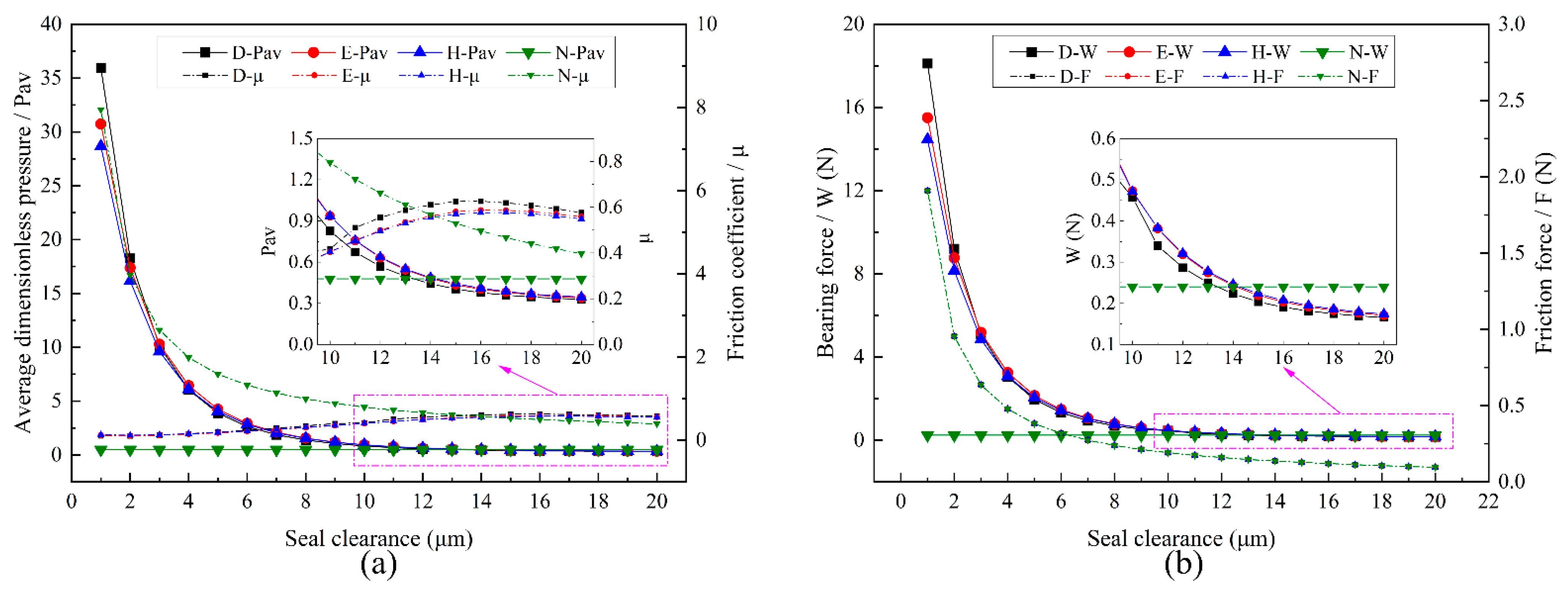
3.3. Effect of the Seal Clearance

Figure 7 shows the change of sealing performance parameters of the three textured and non-textured finger seals with various seal clearances (hc) at the rotation speed of 20,000 rpm, inlet/outlet pressure difference of 0.5 MPa, and hydrodynamic viscosity of 0.0228 Pa·s. In the case of non-texture, with the increase of hc, the N-μ decreases exponentially, whereas the N-Pav remains the same. This shows that (1) the increase of hc does not change the pressure distribution; (2) at the constant rotation speed, in line with the definition of hydrodynamic viscosity (i.e., the ratio of viscous shear stress to fluid velocity gradient) and the assumption A6 (i.e., the variations of hydrodynamic viscosity is ignored), the larger hc leads to the smaller velocity gradient in the calculation domain, resulting in the corresponding smaller shear stress, so the N-F decreases with the increase of the hc, as shown in Figure 7b; and (3) as the N-F decreases exponentially and the N-W remains unchanged, the N-μ also decreases exponentially, specifically, the N-μ first decreases sharply, and then flattens gradually.
On contrary, with the increase of hc, the Pav of the textured finger seals decreases exponentially, whereas the μ increases first and then decreases slightly. The reasons are as follows: (1) at the constant PI and rotation speed, the bearing capacity in the textured calculation domain decreases with the increase of hc, as shown in Figure 7b, and the increasing rate of the hc decreases gradually. Therefore, the Pav in the calculation domain first decreases sharply and then flattens. (2) With the increase of hc, the F and W of the textured finger seals decrease at an inconsistent rate, see Figure 7b, which leads to the phenomenon that the μ with surface textures first increases and then decreases slightly; (3) To better improve the textured finger-sealing performance, the hc should be as shallow as possible. Once the hc exceeds a certain value, the texture will lose the anti-friction and anti-wear effect or even deteriorate the sealing performance. For instance, when the hc is 10 μm, the N-Pav is 0.478, and the N-μ is 0.795, whereas the D-Pav is 0.828 (1.731 times of N-Pav), and the D-μ is 0.418 (52.54% of N-μ); however, when the hc is 15 μm, the N-Pav is 0.478, and the N-μ is 0.53, whereas the D-Pav is 0.403 (84.39% of N-Pav) and the D-μ is 0.625 (1.18 times of N-μ), in this case, the surface texture has lost the antifriction and wear resistance. (4) In Figure 7b, the friction curves of three textures and non-texture are coincident. The reason is the same as described previously in Section 3.1.

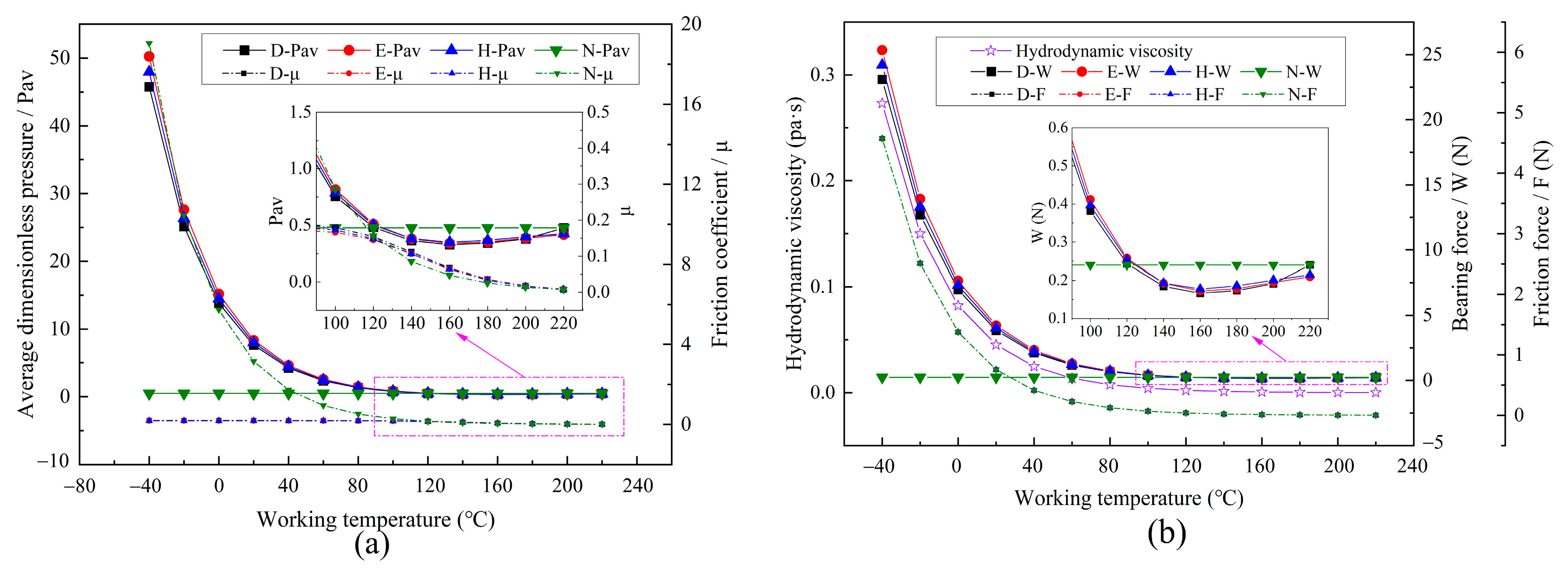
3.4. Effect of the Working Temperature

Due to the large temperature difference and rapid transformation of the operating environment in aviation aircraft, in this paper, the influence of hydrodynamic viscosity change on textured finger seal is analyzed in the working temperature (T) range of −40–200 °C.
Figure 8 shows the change of sealing performance parameters of the three textured and the non-textured finger seals under various Ts at the rotation speed of 20,000 rpm, the pressure difference of 0.5 MPa, and seal clearance of 5 μm. In the case of non-texture, the N-μ decreases exponentially with the increase of T, whereas the N-Pav remains the same. This shows that (1) the increasing T does not change the pressure distribution; (2) in line with the definition of hydrodynamic viscosity (i.e., the ratio of viscous shear stress to velocity gradient of the fluid), the decrease of hydrodynamic viscosity leads to the decrease of shear stress whereas the fluid velocity gradient remains the same, which results in the phenomenon of the N-F and N-μ directly proportional to hydrodynamic viscosity. In addition, viscosity-temperature variation calculated in Equation (3) shows that the change rate of hydrodynamic viscosity is exponentially related to temperature change. Therefore, with the increase of T, the hydrodynamic viscosity decreases exponentially (see Figure 8b), resulting in the phenomenon that N-F and N-μ decrease exponentially.
On the contrary, the μ of the three textured finger seals changes slightly with the increase of T, whereas the Pav and W decrease exponentially. This shows that (1) the hydrodynamic effect is produced in three textured calculation domains, which changes the pressure distribution, and improves the bearing capacity of the fluid. (2) As the T increases, the hydrodynamic viscosity decreases significantly, leading to an exponential decrease of both F and W with consistent variation ranges. Therefore, the μ of the three textured finger seals changes slightly. (3) In Figure 8b, the friction curves of three textures and the non-texture are coincident. The reason is the same as described previously in Section 3.1. (4) Overall, textured finger seals reflect better performance advantages, especially at low T.
Furthermore, when the T is higher than 120 °C (η ≤ 0.0022 Pa·s), the N-μ is slightly smaller than that of textured finger seals, whereas the N-Pav and N-W are larger comparatively. For example, when T = 140 °C, the N-Pav is 0.478 and the N-μ is 0.086, whereas the H-Pav is 0.383 (80.05% of N-Pav) and the H-μ is 0.107 (1.246 times of N-μ). To further explain this phenomenon, in Figure 9, the pressure contour and nephogram of the hexagon texture and non-texture in the calculation domain are compared at the working temperature of 140 °C (η = 0.0012 Pa·s). As shown in Figure 9a,c the fluid pressure drop of the hexagon texture is more intense after the fluid passes through the texture region, whereas in Figure 9b,d, although a certain hydrodynamic effect is generated in the hexagon texture calculation domain, due to the small F generated by the fluid with low hydrodynamic viscosity, the fluid cannot follow the rotor motion well, resulting in serious dissociation and streamline bending in the texture region. Specifically, the streamline velocities from different directions in the texture region offset each other, resulting in local head loss and a large pressure drop. Therefore, the Pav and W in the three textured calculation domains are slightly lower than that of the non-texture.

4. Conclusions

In this study, through numerical modeling and comprehensive analysis, the effects of three snake-bioinspired surface textures (i.e., diamond, ellipse, and hexagon) on finger-sealing performance have been investigated under varied working conditions. The results demonstrate that the surface textures can play a significant and promising role in improving finger-sealing performance under varied working conditions. The main conclusions are presented as follows:
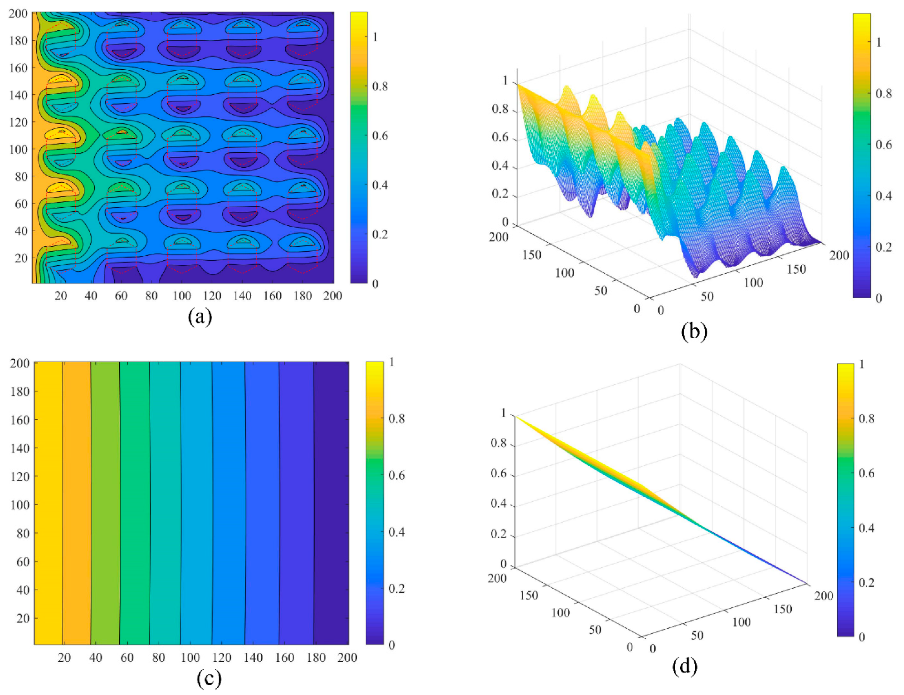
  • The hydrodynamic effect and cavitation phenomenon are produced in the three textured calculation domains. There is a set of peak and valley values of the dimensionless pressure (P) in each micro-texture unit, which effectively improves the bearing capacity of the finger seal.
  • Within the rotation speed range of 3000~30,000 rpm, the finger seals with snake-bioinspired textures have better anti-friction and wear resistance as compared to the non-textured counterpart. Moreover, the higher the rotation speed, the more obvious the advantage of the textured finger seals.
  • Within the pressure difference range of 0~1 MPa, textured finger seals have excellent antifriction and wear resistance. However, once it exceeds 1 MPa, the axial movement of the fluid is enhanced, and the pressure relief of the textured finger seals is stronger, which can weaken the effects of textured finger seals or even worsen.
  • For good antifriction and wear resistance of the textured finger seals, the seal clearance should be as shallow as possible (≤10 μm), and the working temperature should be as low as possible (≤120 °C).
  • Under the varied working conditions, the ellipse textured finger seal has a higher average dimensionless pressure (Pav) and a lower friction coefficient (μ) compared with the diamond and hexagon ones, which indicates its better anti-friction and wear resistance.

Author Contributions

Conceptualization, L.C., Y.Z. and Y.C.; methodology, L.C. and J.W.; software, L.C.; validation, L.C.; formal analysis, L.C.; investigation, L.C.; resources, Y.Z. and Y.C.; data curation, L.C.; writing—original draft preparation, L.C.; writing—review and editing, M.W. and Y.Z.; visualization, L.C. and J.W.; supervision, M.W. and Y.Z.; project administration, Y.Z. and M.W.; funding acquisition, Y.Z. All authors have read and agreed to the published version of the manuscript.

Funding

This research is supported by the National Natural Science Foundation of China (Grant Nos. 52075436, 51305343) and the Education Department of Shaanxi Province (Grant No. 19JC030).

Institutional Review Board Statement

Not applicable.

Informed Consent Statement

Not applicable.

Data Availability Statement

Not applicable.

Acknowledgments

The author(s) would like to thank Maigoo for providing the Snake images (accessed on 26 May 2022, https://www.maigoo.com/tuku/524184.html).

Conflicts of Interest

The authors declare no conflict of interest.

Nomenclature

SymbolDescriptionUnit
ErrpError limit
FFriction forceN
hThickness of local fluid filmm
HDimensionless thickness of the fluid film
hcSeal clearance (installation clearance between rotor and finger feet)m
htTexture depthm
kIteration number
LTypical length of friction pairm
pFluid film pressureMPa
PDimensionless pressure of the fluid film
paAmbient pressureMPa
PavAverage dimensionless pressure
pcCavitation pressureMPa
pIInlet pressure (also refers to the inlet/outlet pressure difference of finger seal)MPa
pOOutlet pressure (set to 0)MPa
RRotor radiusmm
STexture area ratiom2
SrArea of the rotorm2
StArea of the surface texturem2
TWorking temperature°C
WBearing force of the fluid filmN
XDimensionless horizontal coordinate
xrRotor lengthm
YDimensionless longitudinal coordinate
yrRotor widthm
αRelaxation factor
δClearance ratio
ηHydrodynamic viscosityPa·s
ΛWorking condition parameter of finger seal
μFriction coefficient
ωRotation speedrpm
ΩcRegion of cavitation
ΩtRegion of texture

Appendix A

For the finger seal, the contact pressure between the finger feet and the rotor is generated due to the radial runout of the rotor, and there is relative movement between the two surfaces, so the wear performance of the finger seal is mainly reflected by the wear condition of between the moving pairs. Under certain material and working conditions, the wear performance can be characterized by contact pressure between the finger feet and the rotor.
In the friction simulation analysis of this paper, to meet the working conditions of the finger seal, the dynamic analysis model of the finger seal is first established, and the average contact pressure between the finger feet and the rotor is calculated to be 0.29 MPa. The specific modeling and analysis process are as follows.
Table A1 shows the structural parameters in finger seal contact simulation, the meaning of structural parameters can be referred to [1].
Table A1. Structure parameters of finger seal contact simulation.
Structure ParametersValue
Rotor radius (mm)40
Out radius of finger seal (mm)55
Root radius of finger seal (mm)50
Base radius (mm)8
Number of finger beams (per piece)33
Finger beam clearance angle (°)0.3
Downstream protection height (mm)0.5
Finger laminate thickness (mm)0.2
According to the structural parameters in Table A1, the simulation model is established in ANSYS APDL [29]. The simulation model is shown in Figure A1. Apply the load after establishing contact pairs and fixed constraints. The load is applied in three steps, as shown in Figure A2: (a) an axial pressure of 0.1~0.5 MPa is applied to the high-pressure finger laminate, indicating the pressure difference; (b) maintain the pressure and apply a displacement of 0.3e3m along the radial direction of the rotor to apply the rotor excitation (the corresponding rotor speed is 6000 r/min); (c) return the rotor to its original position.
Figure A1. Simulation model and boundary conditions of finger seal dynamic contact.
Machines 10 00569 g0a1
Figure A2. Schematic diagram of adding load step for finger seal contact simulation: (a) applying axial pressure to the high-pressure finger laminate; (b) applying displacement in the radial direction of the rotor; (c) returning the rotor to its original position.
Machines 10 00569 g0a2
When the finger beam moves upward with the excitation of the rotor, a certain pressure is generated between the finger feet and the rotor. When the rotor returns to the original position, the finger beam cannot return to the original position in time due to the friction between the finger laminates and the back plate. Therefore, there is a certain leakage gap between the finger feet and the rotor, as shown in Figure A2c.
After the finite element simulation, the contact pressure of each node on the bottom surface of the finger feet in the calculation result of load step (b) is extracted to obtain its average contact pressure. As shown in Figure A3.
Figure A3. Average contact pressure of finger seal under different pressure differences.
Machines 10 00569 g0a3

References

  1. Zhang, Y.C.; Yin, M.H.; Zeng, Q.R.; Wang, T.; Wang, R. Theoretical and Experimental Investigation of Variable Stiffness Finger Seal. Tribol. Trans. 2020, 63, 634–646. [Google Scholar] [CrossRef]
  2. Chen, L.; Zhang, Y.; Cui, Y.; Zhi, B.; Wang, J.; Wang, M. Numerical Investigation on Sealing Performance of Non-Contact Finger Seal with Herringbone Groove Surface Topography. Surf. Topogr. Metrol. Prop. 2021, 9, 45041. [Google Scholar] [CrossRef]
  3. Zhao, H.L.; Chen, G.D.; Wang, L.N.; Su, H. Dynamic Analysis of Finger Seal in the Complex Working State. Proc. Inst. Mech. Eng. Part G-J. Aerosp. Eng. 2019, 233, 125–137. [Google Scholar] [CrossRef]
  4. Hua-lei, B.A.I. Analysis of Hysteresis and Forming Method for Finger Seal with Arc Shape Curve. Aeroengine 2014, 40, 49–51. [Google Scholar] [CrossRef]
  5. Lu, F.; Liu, J.; Lu, H.Y. Experimental Study on Leakage and Wear Characteristics of C/C Composite Finger Seal. Ind. Lubr. Tribol. 2020, 72, 1133–1138. [Google Scholar] [CrossRef]
  6. Zhang, Y.C.; Si, C.G.; Zhang, Y.T.; Zhang, D.Y.; Cui, Y.H. Effect of Wear-Resistant Coatings on the Comprehensive Performance of Finger Seal. Proc. Inst. Mech. Eng. Part J-J. Eng. Tribol. 2019, 233, 570–579. [Google Scholar] [CrossRef]
  7. Wang, J.; Zhang, Y.; Cui, Y.; Zhai, Z.; Chen, L.; Lu, J. Numerical Investigation of Residual Stress in Plasma Sprayed Antifriction Wear-Resistant Sealing Coatings on GH4169 Superalloy Substrate. Mater. Today Commun. 2022, 31, 103595. [Google Scholar] [CrossRef]
  8. Zhao, H.; Sun, Q.; Deng, X.; Cui, J. Earthworm-Inspired Rough Polymer Coatings with Self-Replenishing Lubrication for Adaptive Friction-Reduction and Antifouling Surfaces. Adv. Mater. 2018, 30, e1802141. [Google Scholar] [CrossRef]
  9. Li, C.; Yang, Y.; Yang, L.; Shi, Z. Biomimetic Anti-Adhesive Surface Microstructures on Electrosurgical Blade Fabricated by Long-Pulse Laser Inspired by Pangolin Scales. Micromachines 2019, 10, 816. [Google Scholar] [CrossRef] [Green Version]
  10. Abdel-Aal, H.A.; El Mansori, M.; Zahouani, H. A Comparative Study of Frictional Response of Shed Snakeskin and Human Skin. Wear 2017, 376, 281–294. [Google Scholar] [CrossRef] [Green Version]
  11. Quan, S.; Yong, G.; Jun, G.; Liu, X.; Jin, Y.; Yang, S. Effect of Fish Scale Texture on Friction Performance for Reciprocating Pair with High Velocity. Ind. Lubr. Tribol. 2020, 72, 497–502. [Google Scholar] [CrossRef]
  12. Yamagishi, R.; Maeda, H.; Kasuga, T. Water Wettability Dependence on Surface Structure of a Snail Shell. Bioinspir. Biomim. 2020, 15, 036001. [Google Scholar] [CrossRef] [PubMed]
  13. Geraldi, N.R.; Dodd, L.E.; Xu, B.B.; Wood, D.; Wells, G.G.; McHale, G.; Newton, M.I. Bioinspired Nanoparticle Spray-Coating for Superhydrophobic Flexible Materials with Oil/Water Separation Capabilities. Bioinspir. Biomim. 2018, 13, 21931884. [Google Scholar] [CrossRef] [PubMed]
  14. Lin, Q.; Wei, Z.; Wang, N.; Chen, W. Effect of Large-Area Texture/Slip Surface on Journal Bearing Considering Cavitation. Ind. Lubr. Tribol. 2015, 67, 216–226. [Google Scholar] [CrossRef]
  15. Yin, B.; Zhou, H.; Xu, B.; Jia, H. The Influence of Roughness Distribution Characteristic on the Lubrication Performance of Textured Cylinder Liners. Ind. Lubr. Tribol. 2019, 71, 486–493. [Google Scholar] [CrossRef]
  16. Jiang, J.; Zhao, W.; Peng, X.; Li, J. A Novel Design for Discrete Surface Texture on Gas Face Seals Based on a Superposed Groove Model. Tribol. Int. 2020, 147, 325. [Google Scholar] [CrossRef]
  17. Pan, C.; Li, Q.; Hu, K.; Jiao, Y.; Song, Y. Study on Surface Roughness of Gcr15 Machined by Micro-Texture PCBN Tools. Machines 2018, 6, 42. [Google Scholar] [CrossRef] [Green Version]
  18. Liu, X.; Zhang, J.; Li, L.; Huang, W. Theoretical and Simulation Analysis on Fabrication of Micro-Textured Surface under Intermittent Cutting Condition by One-Dimensional Ultrasonic Vibration-Assisted Turning. Machines 2022, 10, 166. [Google Scholar] [CrossRef]
  19. Korpela, T.; Suvanto, M.; Pakkanen, T.T. Friction and Wear of Periodically Micro-Patterned Polypropylene in Dry Sliding. Wear 2012, 289, 1–8. [Google Scholar] [CrossRef]
  20. Pattnayak, M.R.; Pandey, R.K.; Dutt, J.K. Effects of New Micro-Pocketed Bore Surface Topographies on the Performance Behaviours of Aerodynamic Journal Bearing. Surf. Topogr. Metrol. Prop. 2021, 9, 2. [Google Scholar] [CrossRef]
  21. Tala-Ighil, N.; Fillon, M. A Numerical Investigation of Both Thermal and Texturing Surface Effects on the Journal Bearings Static Characteristics. Tribol. Int. 2015, 90, 228–239. [Google Scholar] [CrossRef]
  22. Tiner, C.; Bapat, S.; Nath, S.D.; Atre, S.V.; Malshe, A. Exploring Convergence of Snake-Skin-Inspired Texture Designs and Additive Manufacturing for Mechanical Traction. Procedia Manuf. 2019, 34, 640–646. [Google Scholar] [CrossRef]
  23. Ballesteros, L.M.; Zuluaga, E.; Cuervo, P.; Rudas, J.S.; Toro, A. Tribological Behavior of Polymeric 3D-Printed Surfaces with Deterministic Patterns Inspired in Snake Skin Morphology. Surf. Topogr. Metrol. Prop. 2021, 9, 014002. [Google Scholar] [CrossRef]
  24. Greiner, C.; Schäfer, M. Bio-Inspired Scale-like Surface Textures and Their Tribological Properties. Bioinspiration Biomim. 2015, 10, 44001. [Google Scholar] [CrossRef]
  25. Cuervo, P.; López, D.A.; Cano, J.P.; Sánchez, J.C.; Rudas, S.; Estupiñán, H.; Toro, A.; Abdel-Aal, H.A. Development of Low Friction Snake-Inspired Deterministic Textured Surfaces. Surf. Topogr. Metrol. Prop. 2016, 4, 024013. [Google Scholar] [CrossRef] [Green Version]
  26. Sánchez, J.C.; Toro, A.; Estupiñán, H.A.; Leighton, G.J.T.; Endrino, J.L. Fabrication of Bio-Inspired Deterministic Surfaces by Photochemical Machining for Tribological Applications. Tribol. Int. 2020, 150, 1353–1357. [Google Scholar] [CrossRef]
  27. Bapat, S.; Tiner, C.; Rajurkar, K.; Nath, S.; Atre, S.; Malshe, A. Understanding Biologicalisation of the Snake-Skin Inspired Textures through Additive Manufacturing for Mechanical Traction. CIRP Ann. 2020, 69, 201–204. [Google Scholar] [CrossRef]
  28. Chen, L.; Zhang, Y.; Cui, Y.; Wang, J.; Wang, M. Effect of Snake-Biomimetic Surface Texture on Finger Sealing Performance under Hydrodynamic Lubrication. Surf. Topogr. Metrol. Prop. 2021, 9, 035040. [Google Scholar] [CrossRef]
  29. Yin, M.; Zhang, Y.; Zhou, R.; Zhai, Z.; Wang, J.; Cui, Y.; Li, D. Friction Mechanism and Application of PTFE Coating in Finger Seal. Tribol. Trans. 2021, 65, 260–269. [Google Scholar] [CrossRef]
  30. Liu, D.; Wang, S.; Zhang, C.; Tomovic, M.M. Numerical Study of the Effects of Textured Shaft on the Wear of Rotary Lip Seals. Tribol. Int. 2019, 138, 215–238. [Google Scholar] [CrossRef]
  31. Uddin, M.S.; Liu, Y.W. Design and Optimization of a New Geometric Texture Shape for the Enhancement of Hydrodynamic Lubrication Performance of Parallel Slider Surfaces. Biosurface Biotribol. 2016, 2, 59–69. [Google Scholar] [CrossRef] [Green Version]
  32. Venkateswara babu, P.; Syed, I.; BenBeera, S. Experimental Investigation on Effects of Positive Texturing on Friction and Wear Reduction of Piston Ring/Cylinder Liner System. Mater. Today Proc. 2020, 24, 1112–1121. [Google Scholar] [CrossRef]
  33. Liu, W.; Ni, H.; Chen, H.; Wang, P. Numerical Simulation and Experimental Investigation on Tribological Performance of Micro-Dimples Textured Surface under Hydrodynamic Lubrication. Int. J. Mech. Sci. 2019, 163, 105095. [Google Scholar] [CrossRef]
  34. Liu, W.; Ni, H.; Wang, P.; Chen, H. Investigation on the Tribological Performance of Micro-Dimples Textured Surface Combined with Longitudinal or Transverse Vibration under Hydrodynamic Lubrication. Int. J. Mech. Sci. 2020, 174, 105474. [Google Scholar] [CrossRef]
  35. Shen, Z.; Wang, F.; Chen, Z.; Ruan, X.; Zeng, H.; Wang, J.; An, Y.; Fan, X. Numerical Simulation of Lubrication Performance on Chevron Textured Surface under Hydrodynamic Lubrication. Tribol. Int. 2021, 154, 106704. [Google Scholar] [CrossRef]
  36. Ma, C.; Zhu, H.; Sun, J. Applicable Equation Study of Lubrication Calculation of Surface Texture Based on CFD Analysis. Chin. J. Mech. Eng. 2011, 47, 95. [Google Scholar] [CrossRef]
  37. Dowson, D.; Taylor, C.M. Cavitation in Bearings. Annu. Rev. Fluid Mech. 1979, 11, 35–66. [Google Scholar] [CrossRef]
  38. Wang, D.A. Enhancing LpCMFD Acceleration with Successive Overrelaxation for Neutron Transport Source Iteration. Nucl. Sci. Eng. 2021, 195, 1–12. [Google Scholar] [CrossRef]
  39. Liu, B.; Ma, K. Comparison of Elevated Temperature Performance between Domestic Aviation Lubricant and Russian Aviation Lubricant. Synth. Lubr. 2020, 47, 37–39. [Google Scholar] [CrossRef]
Figure 1. Schematic diagram of the finger seal: (a) general structure, (b) single finger laminate, and (c) main dimensions.
Machines 10 00569 g001
Figure 2. Illustration of the simplified model of the friction simulation and results: (a) simplified model and (b) simulation results.
Machines 10 00569 g002
Figure 3. Illustration of finger seal with surface textures: (a) textured finger seal, (b) boundary conditions of the calculation domain, (c) geometrical model of diamond texture, (d) ellipse texture, and (e) hexagon texture.
Machines 10 00569 g003
Figure 4. Comparison of dimensionless pressure of three textures and non-texture: (a) diamond texture, (b) ellipse texture, (c) hexagon texture, and (d) non-texture.
Machines 10 00569 g004
Figure 5. Effect of rotation speed on sealing performance: (a) average dimensionless pressure and friction coefficient, and (b) bearing force and friction force.
Machines 10 00569 g005
Figure 6. Effect of pressure difference on average dimensionless pressure and friction coefficient: (a) 20,000 rpm and (b) 5000 rpm.
Machines 10 00569 g006
Figure 7. Effect of seal clearance on sealing performance: (a) average dimensionless pressure and friction coefficient, and (b) bearing force and friction force.
Machines 10 00569 g007
Figure 8. Effect of working temperature on sealing performance: (a) average dimensionless pressure and friction coefficient; (b) bearing force and friction force.
Machines 10 00569 g008
Figure 9. Dimensionless pressure in different calculation domains at the working temperature of 140 °C: (a) contour of hexagon texture; (b) nephogram of hexagon texture; (c) contour of the non-texture; (d) nephogram of the non-texture.
Machines 10 00569 g009
Table 1. Snakeskin-inspired surface textures and geometrical parameters.
Texture TypeSnakeskin Texture ShapeGeometric Parameter (μm)Area (μm²)
Ellipse
(E)
Machines 10 00569 i001Long axis = 130.3;
Short axis = 97.72
10,000
Diamond
(D)
Machines 10 00569 i002Long diagonal = 163.3;
Short diagonal = 122.47
Hexagon
(H)
Machines 10 00569 i003Side length = 62.04
Triangle
(T)
Machines 10 00569 i004Side length = 151.97
Table 2. Dynamic simulation results and friction simulation settings.
Dynamic Simulation Data (Appendix A)PV ValueFriction Simulation Settings
Pressure
(MPa)
Rotation Speed
(rpm)
Rotor Radius
(mm)
(MPa·m/s)Velocity
(m/s)
Pressure
(MPa)
0.296000407.2817.28
Table 3. Calculation parameters and working condition settings.
Calculation ParametersValue (Range)
Rotor radius/R, (mm)40
Rotation speed/ω, (rpm)3000~30,000
Seal clearance/hc, (μm)1~20
Pressure difference/pI, (MPa)0.1~1.5
Working temperature/T, (°C)−40~200
Hydrodynamic viscosity/η, (Pa·s)0.0002~0.2732
Cavitation pressure/pc, (MPa)0
Texture formsDiamond, Ellipse, and Hexagon
Texture area ratio/S25%
Texture depth/ht, (μm)5
Publisher’s Note: MDPI stays neutral with regard to jurisdictional claims in published maps and institutional affiliations.

