1. Introduction
Electrified transportation, including mass transportation using high-speed electric trains, is in growing demand due to increasing environmental concerns and a need to create a sustainable and more efficient transportation system [
1]. Different levitation and propulsion systems are being developed to improve conventional transportation systems using wheel-on-rail technology [
2,
3,
4,
5,
6]. Magnetic levitation (maglev) systems have been employed as an efficient alternative to wheel-on-rail trains and can be divided into two types; those based on attraction force and those based on repulsive force [
2,
7]. Attraction force maglev, also known as the electromagnetic suspension (EMS), is based on the attraction force between the vehicle-side electromagnets and the ferromagnetic iron guideway. The EMS is inherently unstable and requires sophisticated active control that stabilizes the levitation, which can potentially increase the risk of failure and introduce significant safety concerns. Repulsive force maglev, also known as the electro-dynamic suspension (EDS), is based on the repulsive forces generated from a magnetic field that moves relative to a conductive guideway. The magnetic field is usually created by permanent magnets mounted on the vehicles, but superconducting magnets or electromagnets can also be used. EDS is stable, fail-safe, and less expensive for operation at high speeds.
Regarding propulsion technology, linear motors are considered as the most favorable propulsion technology and are widely used in maglev transportation systems [
2,
7]. Linear motors can be categorized either as linear induction motors (LIM), linear reluctance motors, or linear synchronous motors (LSM) [
7]. Depending on the power supply, a linear motor can be of a short primary or long primary type. In the short primary type the power supply is on the vehicle itself, while in the long primary type, guideway-side power supply is utilized. Short primary LIM offers the lowest infrastructure cost but suffers from reduced efficiency, especially at high speeds, and requires onboard batteries. Long primary LSM with the vehicle-side permanent magnets has the highest efficiency and does not require on-board batteries, but the infrastructure cost is very high [
2,
7].
Maglev systems such as Inductrack are considered as a core technology for Hyperloop transportation [
7,
8]. However, Inductrack systems utilize strong neodymium permanent magnets (PMs) to achieve high levitation force and increase lift to weight ratio [
9,
10,
11,
12,
13]. The use of PMs helps to reduce the power consumed by the levitation system but adds to the weight of the Hyperloop vehicle and significantly increases the cost [
9,
10,
11,
12,
13]. The weight of the PMs can represent between 5 to 10% of the total weight of the Hyperloop vehicle. Besides the high cost of neodymium magnets, there are also geopolitical concerns relating to the security of supply and environmental concerns [
14]. Another challenge for the Inductrack systems is that the lift force is difficult to control as the weight of the Hyperloop vehicle changes depending on passenger loading; the option to control the spacing of the PMs from the conductive surface in order to adjust the lift force requires powerful hydraulic systems and is associated with efficiency loss and increased weight. Therefore, it is important to explore other methods of controlling levitation without the use of PMs.
The utilization of linear induction motors (LIMs) is considered an effective approach to produce frictionless propulsion. LIMs don’t require the use of PMs to operate avoiding the increment of weight and cost of the maglev system. Some attempts have been made to utilize the same LIM [
15,
16,
17,
18,
19,
20] or LSM [
21,
22] for both thrust and lift force control. The main criteria when developing such a system is the ability to operate the linear motor near its maximum efficiency in a wide range of thrust and lift forces and for different lift to thrust ratios while keeping the control simple and easy to implement. Morizane et al. [
15] proposed to use a frequency component synchronous with the LIM speed to produce the lift force. The lift force in this case is attractive, which makes the system mechanically unstable. Furthermore, the additional frequency component is associated with power loss and contributes to the entry/exit end effects at high operating speeds, producing additional drag force which in turn reduces the overall efficiency of the system. Ji et al. [
16] have proposed a non-symmetric double-sided LIM (DSLIM) having a special structure with a secondary plate oriented vertically. This system does not demonstrate the ability to sustain constant lift force while altering the thrust force; furthermore, changing the lift to thrust ratio greatly affects the efficiency. The use of DSLIM with lift force control was proposed in [
17] by modifying the supply phase angle of one primary with respect to that of the other primary. The drawback of this method is that modification of the supply phase angle adversely influences the DSLIM efficiency. Hasirci et al. [
18] proposed a novel topology for maglev systems utilizing air-cored tubular LIM with an open slit sleeve to simultaneously produce levitation, propulsion, and guidance forces. This topology, however, leads to a reduction of power factor and as a result the LIM efficiency is reduced. As can be seen, the main drawback of previously published methods is that simultaneous control of thrust and lift forces confines the LIM to operate with reduced efficiency, increasing overall power consumption.
This study originates from the authors’ previous work [
19,
20], where the electromagnetic performance of an asymmetric double-sided linear induction motor (ADSLIM) was initially studied and independent control of thrust and lift forces were achieved with high efficiency by applying different current amplitudes to upper and lower primaries. One of the main limitations of the previously proposed technique is that it prohibits ADSLIMs to produce a high lift force while operating with a low thrust force. In this article, the authors propose a combination of AC and DC modes of operation to overcome this limitation and present a control framework for a system consisting of several ADSLIMs which allows simultaneous control of thrust and lift force under different operating conditions, particularly high lift to thrust ratios. ADSLIMs with the proposed control algorithm can be easily employed in maglev/Hyperloop systems and have the potential to reduce cost and complexity of these vehicles by achieving simultaneous control of thrust and lift forces under an all-in-one propulsion-levitation system without the need to use PMs.
2. Proposed Motor Structure and Control Method
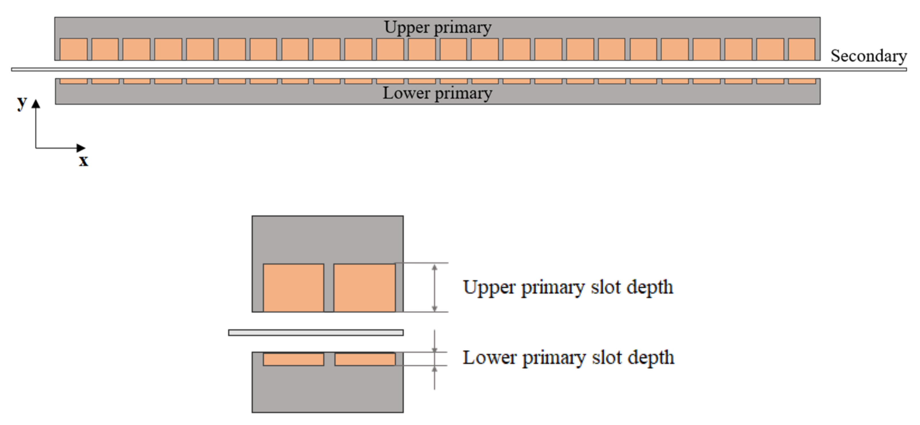
The combined method to control thrust and lift forces is analyzed on a system consisting of DSLIMs with asymmetric upper and lower primary parts. The general view of the ADSLIM used for this analysis is shown in
Figure 1 and
Table 1 shows the general specifications of the ADSLIM. The choice of the ADSLIM is based on the previous study conducted by the authors in [
19] which through careful optimization of ADSLIM parameters such as winding arrangement, number of poles, geometry of the primaries, and taking into account end effects, the authors achieved peak efficiency operation of 80%, indicating that ADSLIM can be a suitable option for high-speed maglev applications in terms of efficiency and power factor.
As can be seen from
Figure 1, the ratio between the depth of upper and lower slots is assumed to be four, resulting in four times fewer turns for the lower primary winding compared to the upper primary winding. The ADSLIM secondary is assumed to be a stationary non-magnetic conductive rail made of aluminum. Three-phase AC currents in both primary parts create a moving magnetic field which induces eddy currents in the conductive secondary. Interaction between the magnetic fields of the primary windings and secondary eddy currents creates an x-axis thrust force. On the other hand, the ADSLIM’s asymmetric structure produces sufficient lift force in the direction of the y-axis, even when energized with equal currents due to the difference of magnetic fields between the lower and upper primary parts.
2.1. Current Balancing Control in AC Mode of Operation and Its Limitations
The current balancing control is based on feeding different AC current magnitudes to the upper and lower primary windings such that the ADSLIM produces the desired thrust and lift forces. Using this control method, the ADSLIM can operate either in AC motoring mode or in AC generating mode (regenerative braking) [
19]. This control method has been initially studied in [
19] in which the general relationships for the resulting thrust and lift forces of the ADSLIM are derived as [
19]:
where
and
are the upper primary thrust and lift forces.
and
are the lower primary thrust and lift forces. The traveling magnetic fields of both primaries produce a thrust force in the same direction (positive sign in Equation (1)) and produce a repulsive force repelling each primary from the secondary plate in opposite directions (negative sign in Equation (2)).
In this mode of operation, as the required thrust force of the ADSLIM decreases, the maximum generated lift force also decreases due to a reduction in the current amplitude and therefore the primary magnetic field. The maximum lift force produced by the ADSLIM while generating certain thrust force is defined by the lift to thrust ratio measured at zero lower primary current:
where
and
are thrust and lift forces,
is the current in the lower primary,
is the maximum lift to thrust ratio of the ADSLIM.
The thrust and lift force control is based on regulating the current amplitudes while the supply frequency can be independently controlled to operate the ADSLIM at slip where the maximum efficiency occurs; the efficiency is defined as the output mechanical power divided by the input electrical power. This allows for the implementation of the thrust and lift force control while operating each ADSLIM at its optimal performance, provided that the required ratio between the thrust and lift force does not exceed .
2.2. Compensating Current Balancing Limitations Using DC Mode of Operation
To overcome the previously described limitation of the current balancing control imposed by
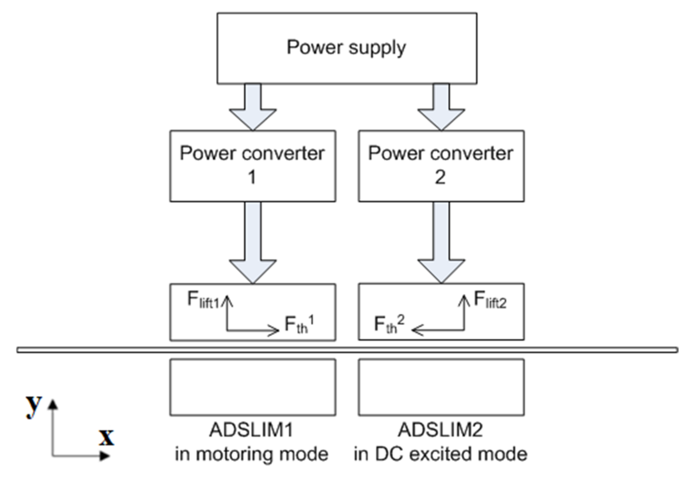
, which limits the lift force at low thrust forces, the authors propose to supply one or several ADSLIMs with DC current, i.e., turning it into an electromagnet. The explanation of the proposed principle for increasing the achievable ratio between the thrust and lift forces is given on the system consisting of two ADSLIMs where one operates in AC motoring mode and the other ADSLIM is fed with DC current.
Figure 2 shows two ADSLIMs placed on the same secondary plate. The first ADSLIM is operated in AC motoring mode and creates the thrust force
in the positive direction of the x-axis. The second ADSLIM is operated in DC mode and creates the drag force
in the opposite direction of the x-axis (negative thrust force). The resulting thrust force can be expressed as follows:
Each ADSLIM generates a lift force in the y-axis direction and the resulting lift force can be expressed as follows:
where
is the first ADSLIM’s lift force and
is the second ADSLIM’s lift force. In this arrangement, although the thrust force produced by ADSLIM1 and the drag force produced by ADSLIM2 oppose each other, lift forces are in the same direction and result in a larger lift force of the system.
In the proposed approach, the AC operating mode is combined with the DC operating mode to cover the full scope of operation including acceleration, cruising and deceleration while maintaining the required lift force. Depending on the operating point, one or several ADSLIMs of the system are fed with DC current while the remaining ADSLIMs operate in AC mode. The current balancing control is applied to all ADSLIMs operating in AC mode. It is assumed that the upper and lower primary windings of each ADSLIM are supplied by separate power converters with independently controlled currents. In the proposed approach, during acceleration from zero to cruising speed in which high thrust force is required, all ADSLIMs of the system operate in AC motoring mode. In this case, high thrust force can be obtained from the system since the lift to thrust ratio of each ADSLIM is lower than . As the required thrust force of the system reduces, the use of AC mode alone will be insufficient to maintain the desired lift force. In this case, some ADSLIMs are operated in the DC mode such that the lift force produced by them compensates for the reduced lift force of ADSLIMs operating in AC mode. As the required thrust force decreases further, more ADSLIMs are controlled in DC mode while other ADSLIMs remain operating in AC mode. In this manner by applying a combination of AC and DC modes, all ADSLIMs of the system together can sustain the required thrust and lift forces without exceeding for each individual ADSLIM.
3. Analysis of ADSLIM Operation in AC Motoring Mode
In the previous studies carried out by the authors in [
19] using the ADSLIM configuration shown in
Figure 1, it was determined that the maximum operating efficiency in the motoring mode occurs at a slip of 0.12 regardless of the primary current value due to a large air gap and near linear motor behavior. The same two-dimensional (2-D) transient electromagnetic finite element (FE) model as [
19] is used in this paper to further study the behavior of the ADSLIM at slip of 0.12 for different combinations of upper and lower primary currents. The ADSLIM specifications presented in
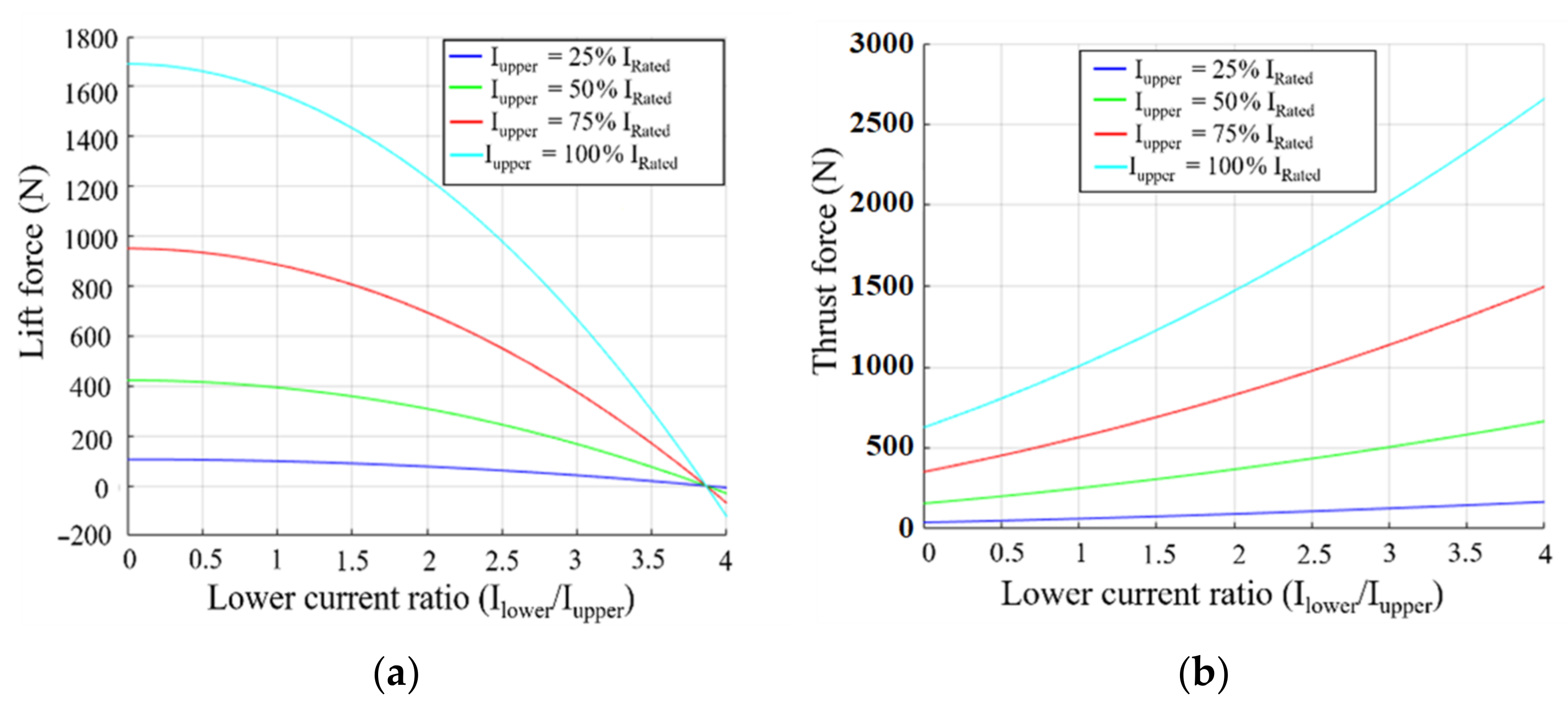
Table 1 are used for the study. The electromagnetic 2-D FE simulations are conducted for several values of the upper primary supply current:
100, 75, 50 and 25% of the rated current of 312.5 A. The lower primary current is varied in the range from zero up to four times the upper primary current. Phase shift and supply frequency are the same for both upper and lower primary windings and the speed is equal to the rated speed of 500 km/h. The corresponding simulation results for the thrust force, lift force, efficiency and lift to thrust ratio are shown in
Figure 3 and
Figure 4 and the magnetic field distribution for the rated operating condition is given in
Figure 5. As can be seen from the FE simulation results, the thrust force increases as currents of the upper and lower primaries increase. The lift force decreases when the lower primary current increases, while it increases with an increase of upper primary current. These results are in full agreement with Equations (1) and (2) and indicate that
and
increase with an increase of the upper primary current. Similarly,
and
increase as the lower primary current increases. Similar to the results previously obtained in [
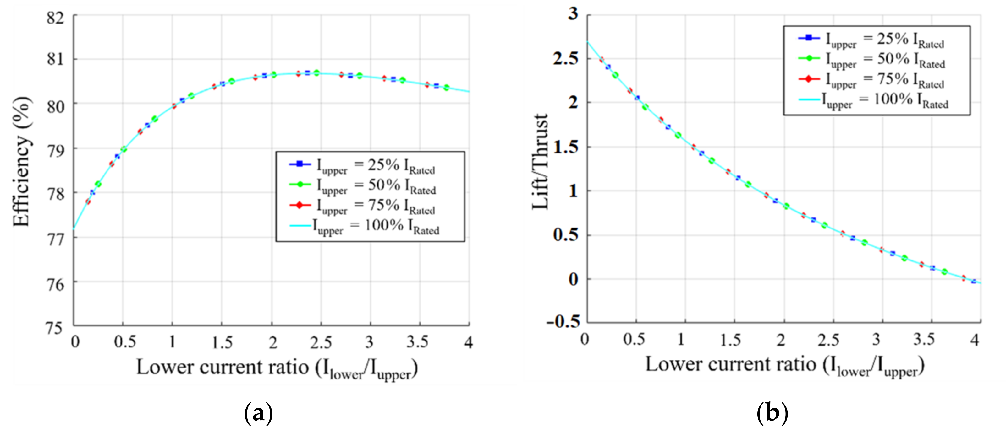
19], the efficiency and lift to thrust ratio are almost independent of the current amplitude but change as the ratio between the lower and upper primary current amplitudes varies. A maximum efficiency of 80.6% is observed when the ratio between the lower and upper primary currents is about 2.4 and the efficiency drops down to 77.2% when the lower primary current is zero. According to
Figure 4b the
value obtained from this analysis for zero lower primary current is 2.7 for all upper primary current values and the
reduces as the lower primary current increases.
4. Analysis of ADSLIM Operation in DC Mode
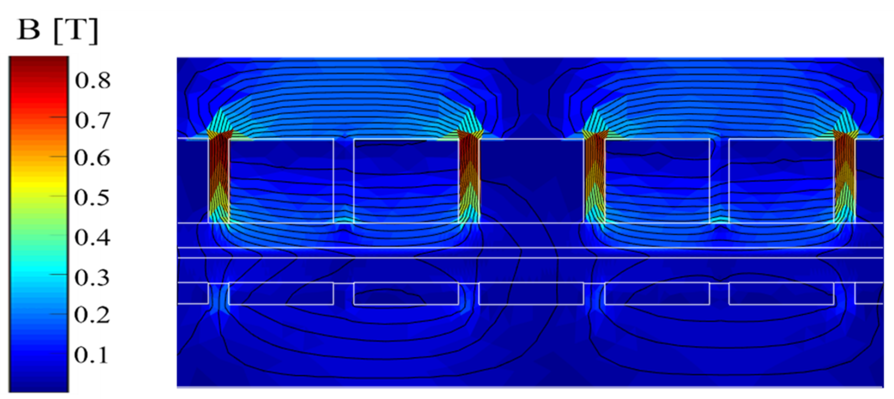
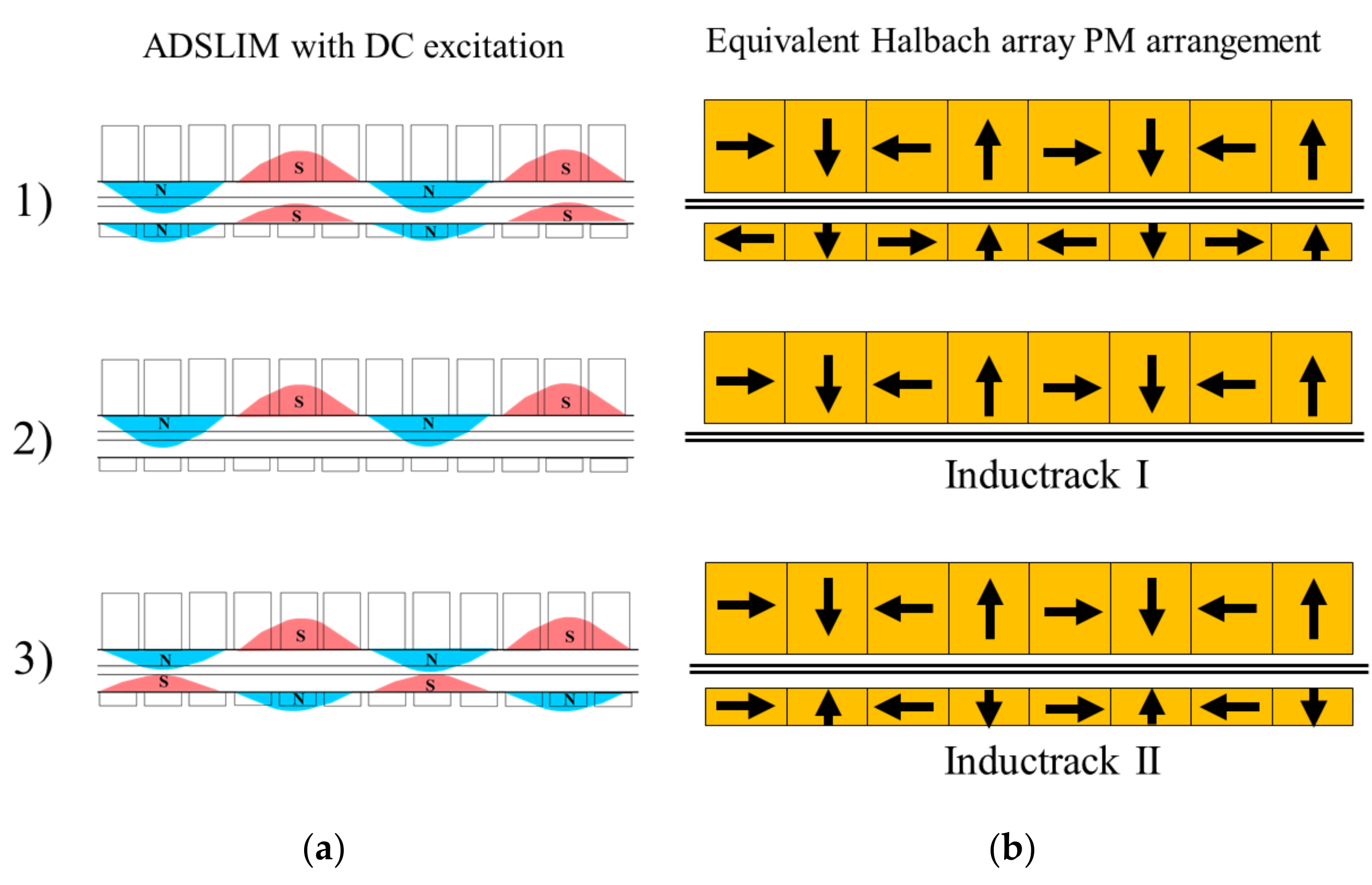
In the DC mode of operation, two terminals of the three-phase star-connected windings of the ADSLIM are connected to a DC voltage supply. The current will flow through two phases while the current in the third phase will be zero. The DC current flowing through two phases will create a static magnetic field with a sinusoidal distribution of the flux as shown in
Figure 6. As the magnetic field wave moves with the primary, eddy currents are induced in the secondary rail and the interaction between the eddy currents and the magnetic field creates a lift force. Three different configurations of the magnetic field are studied: (1) when the magnetic field waves of upper and lower primaries are synphase, (2) when there is no lower primary magnetic field, and (3) when the magnetic field waves of upper and lower primaries are antiphase.
Figure 6 also presents equivalent configurations with Halbach arrays of PMs which would produce the same magnetic field as ADSLIM operating in DC mode. It should be noted that PM arrangement 2 corresponds to Inductrack I configuration and arrangement 3 corresponds to Inductrack II.
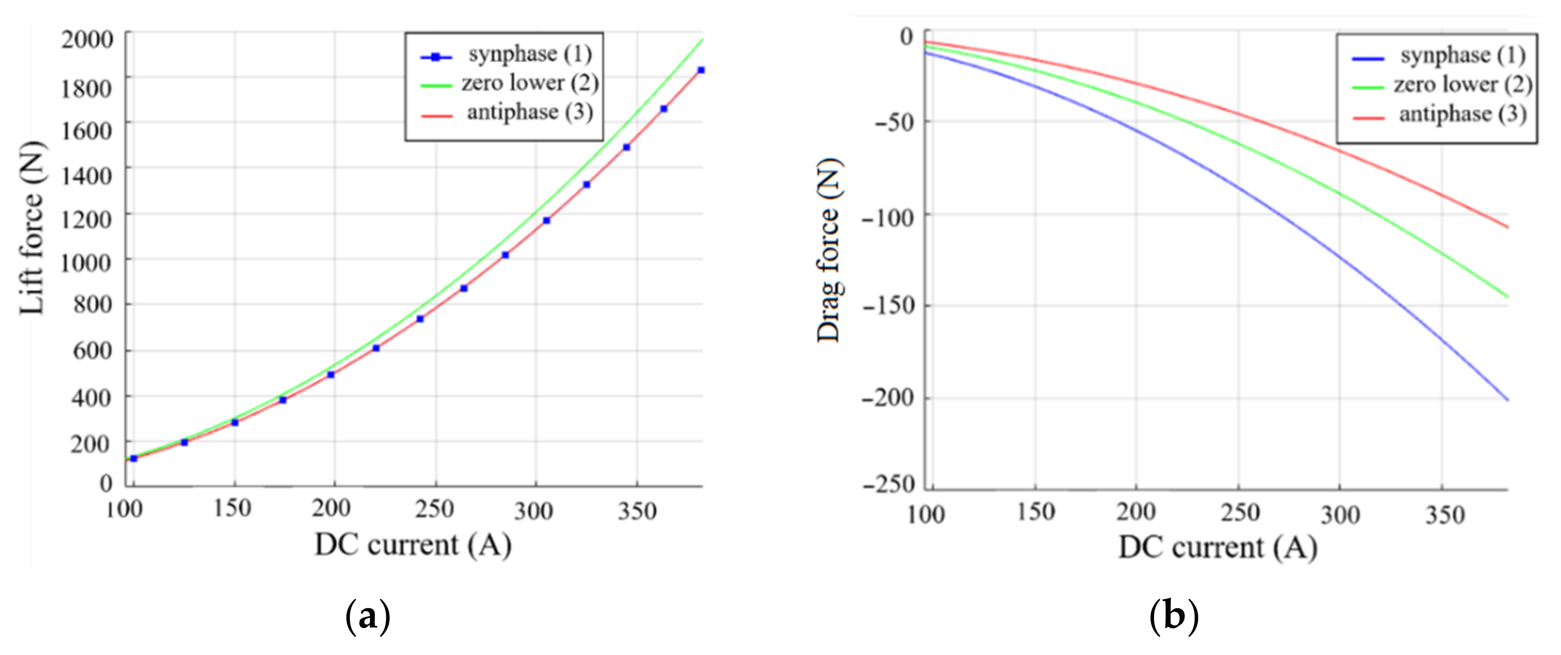
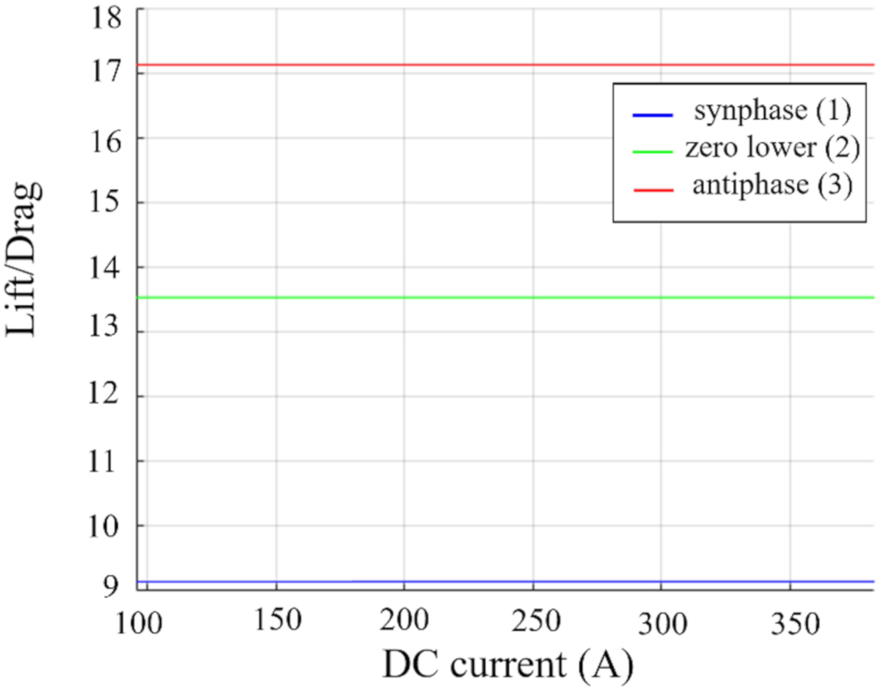
As the magnetic field created by DC current moves along the secondary and produces a lift force, it will also generate drag force (negative thrust force) in the direction opposite to the motion. The drag force is not desirable in this case. As a result, one of the goals of this study is to find the optimal configuration of the magnetic fields of the primaries that generates maximum lift force with minimum drag force, i.e., has the maximum lift to drag ratio (
):
Figure 7 shows FE simulation results of the lift and drag forces for three configurations of the ADSLIM magnetic field for the DC mode of operation.
Figure 8 presents calculated
s for the same three configurations. It can be seen that the third configuration, where the magnetic field waves of upper and lower primaries are antiphase, demonstrates the highest
of 17.1. As a result, this configuration is found to be suitable for the proposed principle of operating ADSLIMs using DC excitation and will be used to study the performance of the system in the following sections.
5. Case Study
To validate the performance of the proposed ADSLIM propulsion-levitation system, the performance metrics of a Hyperloop vehicle shown in
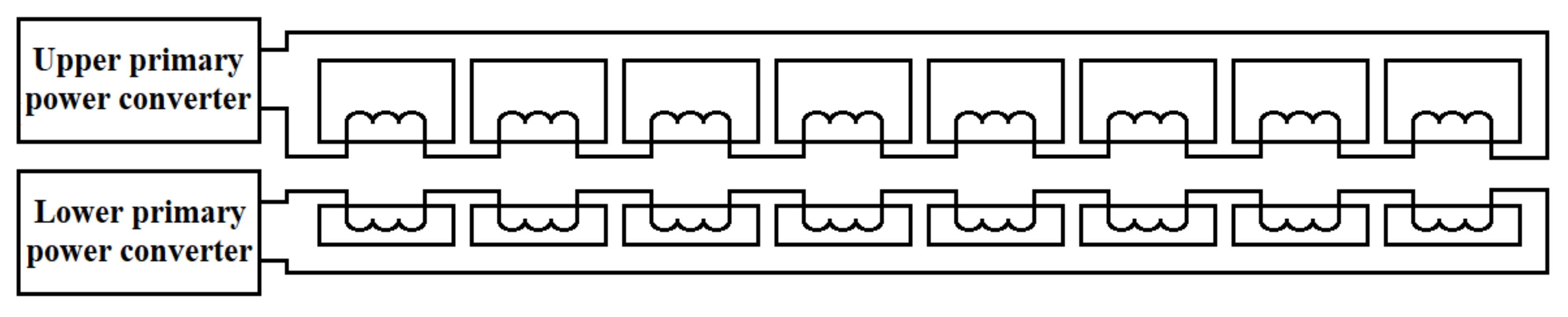
Table 2 are used. The system is comprised of 14 groups of ADSLIMs. Each group includes eight identical ADSLIMs so that the total number of ADSLIMs carried by the vehicle is 112. All upper primary windings of each group are connected in series and are supplied from the same power converter, and therefore carry the same current. This is the same for the lower primary windings of each group. The ADSLIM windings connection within each group is shown in
Figure 9.
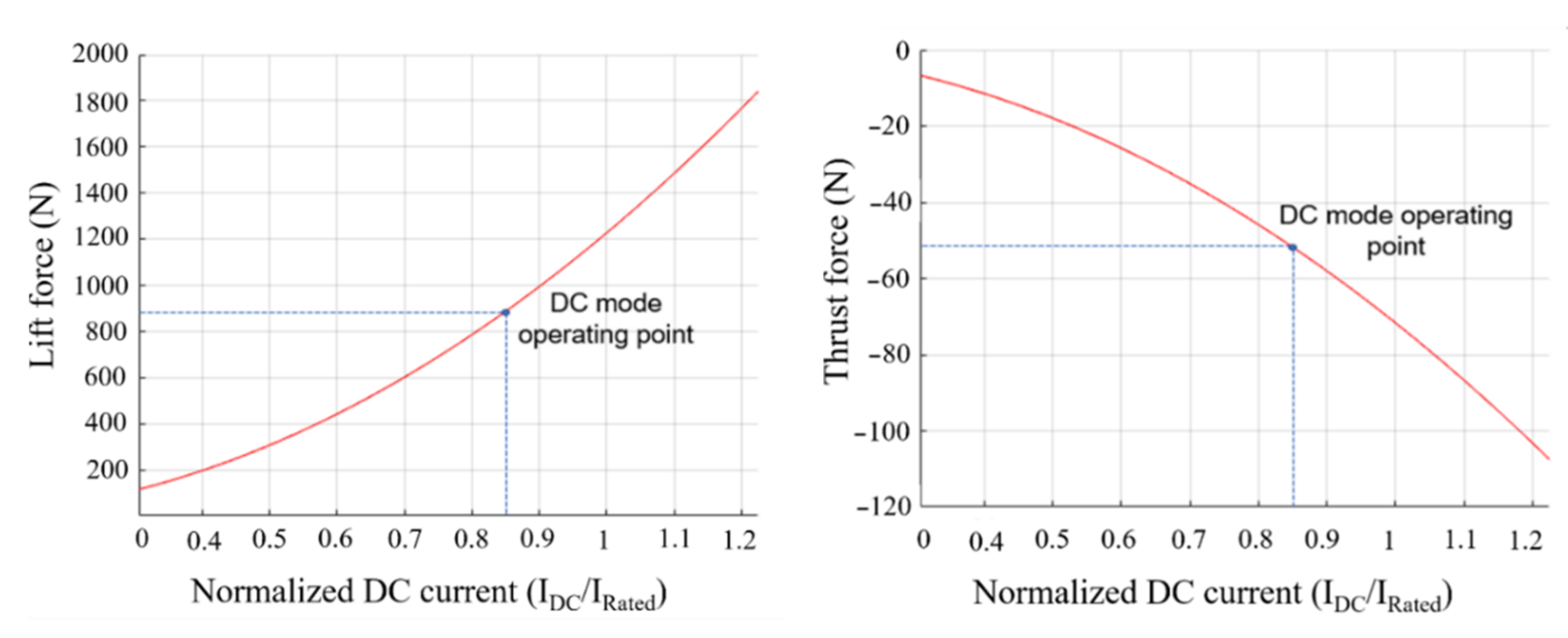
Total thrust force of the vehicle ranging from zero up to a maximum of 60 kN with a constant lift force of 98.1 kN is used to analyze the system. It is assumed that all ADSLIMs produce the same lift force of 875.9 N regardless of the operating mode such that the lift force is equally distributed over the vehicle length. Each group of ADSLIMs operates either in AC mode or in DC mode and the number of groups operating in each mode is determined by the required thrust force of the vehicle.
The DC mode of operation corresponds to configuration (
3) of
Figure 6 which yields the highest LDR among other configurations.
Figure 10 shows the ADSLIM operating point in DC mode that can achieve the required lift force of 875.9 N and
Table 3 summarizes the DC mode operating parameters.
The input electrical power of the ADSLIM in DC mode is calculated as follows:
where
and
are input electrical power and DC current given in
Table 3,
and
are upper and lower primary phase resistances of the ADSLIM given in
Table 1.
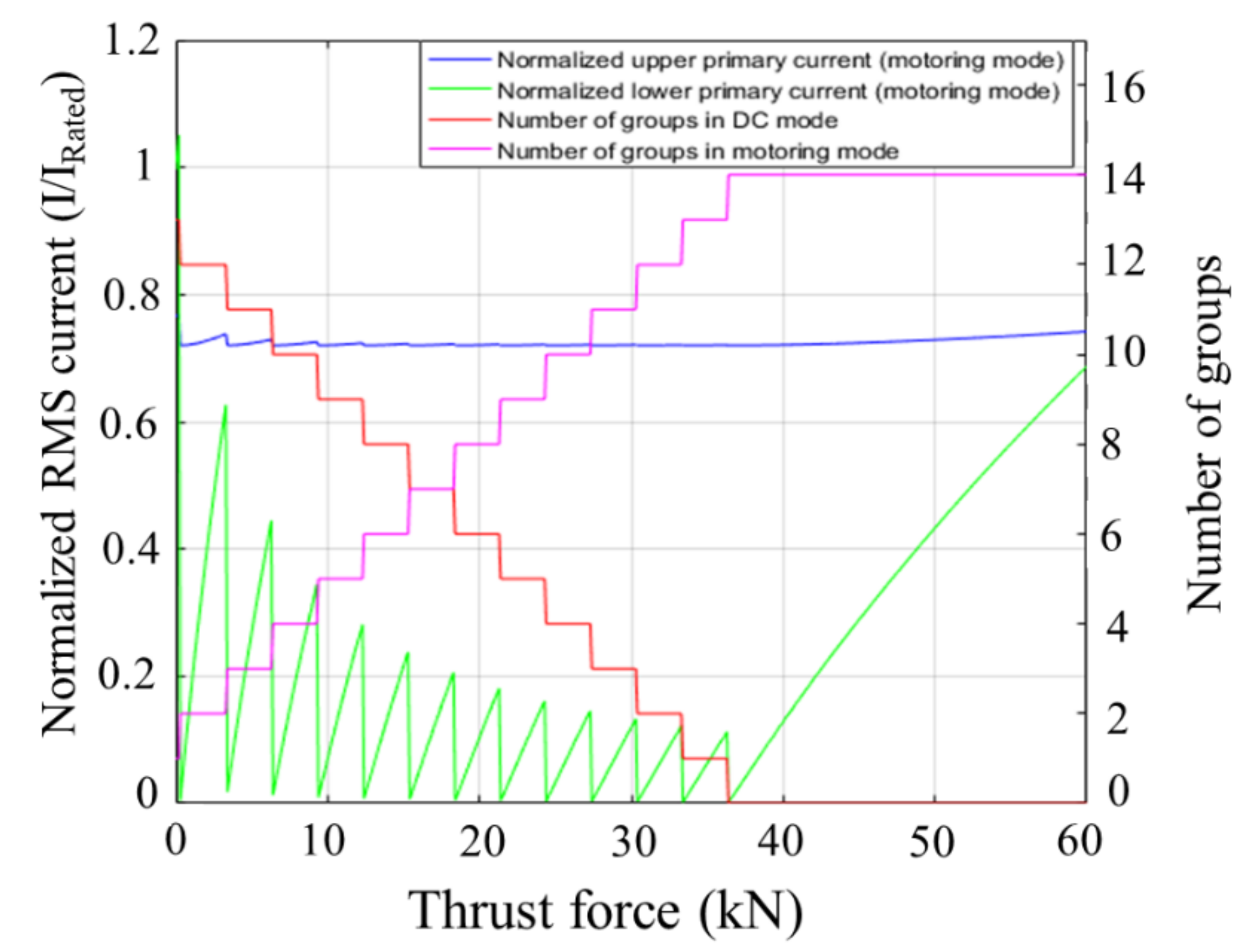
Based on the ADSLIM and Hyperloop vehicle parameters and simulation results provided above, an operation framework is developed that determines the number of groups operating in each mode and calculates the AC mode upper and lower primary currents of ADSLIMs to produce the desired thrust and lift forces. The results of implementing this framework are presented in
Figure 11 which indicates the number of groups operating in each mode for the 0–60 kN range of thrust force. It is more convenient to analyze
Figure 11 in a backward direction starting from maximum thrust force to zero. For the thrust force range of 36.5 to 60 kN, all 14 groups operate in AC motoring mode. In this case study it is assumed that all ADSLIM groups operating in AC motoring mode have the same lower primary currents and the same upper primary currents as shown in
Figure 11 and therefore each ADSLIM in AC mode produces equal thrust and lift forces. As the desired thrust force decreases from 60 to 36.5 kN while the lift force is kept constant, according to Equations (1) and (2) both upper and lower primary currents should also decrease. Also, as
decreases with a decrease of the upper primary current, according to Equation (2),
should be decreased to keep the overall lift force constant. This results in a decrease of the lower primary current. Considering the asymmetric structure of each ADSLIM, this decrease in lower primary current is more rapid. The lower primary current reaches zero when the thrust force drops down to 36.5 kN. The thrust force of 36.5 kN is the minimum threshold for the system under study when all ADSLIMs are operated in AC motoring mode while maintaining the required lift force of 98.1 kN. In other words, they are not able to produce lower thrust force while achieving 98.1 kN lift force since the ratio between the lift force and the thrust force will exceed
. In the proposed approach, in order to achieve a thrust force below 36.5 kN, one group of ADSLIMs are controlled to operate in DC mode. During this transition and to compensate for the emergent drag of ADSLIMs operating in DC mode while sustaining the required lift force, the upper and lower primary currents of the remaining groups operating in AC motoring mode increase as shown in
Figure 11. This change is more evident in the lower primary currents in order to compensate for the increased lift forces produced by ADSLIMs operating in AC motoring with an increased thrust force. As the desired thrust force decreases below 36.5 kN, the lower primary currents of all ADSLIMs operating in AC motoring mode are once again decreased until currents reach zero, which indicates the need for an additional group of ADSLIMs to convert to DC mode of operation. To achieve lower thrust force while maintaining the same lift force of 98.1 kN, more and more groups are controlled to operate in the DC mode of operation, resulting in fewer groups operating in AC motoring mode. For zero thrust force, there is only one group operating in AC motoring mode which is needed to compensate for the drag force produced by the other 13 groups operating in DC mode.
A similar principle for controlling the required lift and thrust forces can be used during acceleration and deceleration. Assuming that during acceleration the thrust force is kept in the range from 36.5 to 60 kN, according to
Figure 11, all ADSLIMs are operated in AC motoring mode and the lift force is regulated solely by controlling the upper and lower primary currents. As the thrust force required for acceleration reduces below the 36.5 kN threshold, groups of ADSLIMs are subsequently controlled to operate in DC mode, in the same manner as described above. On the other hand, the regenerative levitation principle described in [
19] can be utilized during deceleration, which allows kinetic energy conversion to electricity and can be used to charge the battery during regenerative braking. In this case the DC mode is replaced by the AC generating mode combined with the AC motoring mode. Moreover, if the required braking force is high enough such that the generated primary current is able to maintain the required lift force, all ADSLIMs are operated in AC generating mode. As can be seen, the combination of AC motoring mode, DC mode and AC generating mode allows coverage for the full scope of operation including acceleration, cruising, and deceleration.
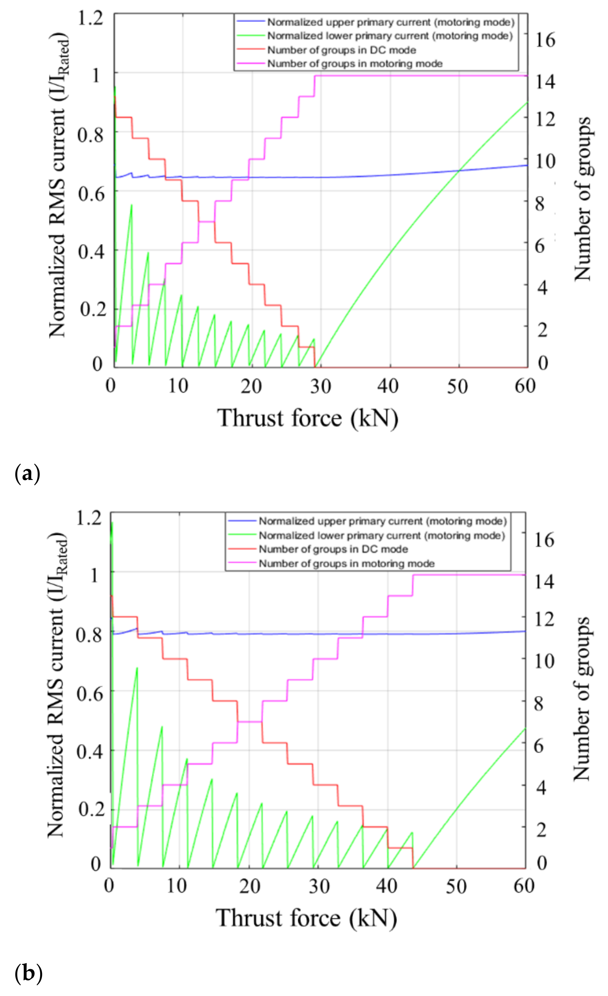
To investigate the effectiveness of the proposed method in achieving a wide range of thrust forces under different passenger loading, a weight variation of ±20% from the nominal vehicle weight is simulated which resembles a change in passenger load. The corresponding operation diagrams of the system for lift forces of 78.5 kN and 117.7 kN which correspond to vehicle weights of 8000 kg and 12,000 kg are shown in
Figure 12a and
Figure 12b, respectively.
6. Comparison with Passive Levitation
This section provides a comparison of power consumption between the proposed ADSLIM-based system and two maglev systems utilizing passive levitation. The two maglev systems are based on Inductrack I and Inductrack II configurations and use conventional DSLIMs to provide the required thrust force while PMs are used to sustain levitation. It is assumed that for this comparison, all three systems operate at the same speed of 500 km/h and maintain a constant lift force of 98.1 kN while generating varying thrust forces in the range of 0–60 kN. To provide a fair comparison, it is assumed that conventional DSLIMs do not produce any lift force and their efficiency is 80.6% for the entire range of thrust force which is equal to the peak efficiency of ADSLIM used in this study. The ADSLIMs are assumed to be operating with a constant slip of 0.12 and their efficiency varies depending on the lower to upper primary current ratio according to
Figure 4. The LDR values of 13.5 and 17.1 are used for the Inductrack I and Inductrack II, which correspond to the PM arrangements 2 and 3 of
Figure 6, respectively. It should be mentioned that according to
Table 3 the LDR of ADSLIM in DC mode is considered to be 17.1, which is the same as the LDR of Inductrack II. For convenience, two Inductrack maglev systems will be referenced as “DSLIM Inductrack I” and “DSLIM Inductrack II”.
To calculate the power consumption (
Pinput) of “DSLIM Inductrack I” and “DSLIM Inductrack II”, the following equations are used:
where
is the thrust force of the vehicle,
is the drag force created by PMs,
is the vehicle speed,
is the efficiency of DSLIM,
is the lift force, and LDR is the lift to drag ratio of the Halbach array arrangement. Equation (8) shows that a portion of the power is used to compensate for the drag force and the rest is used for the propulsion.
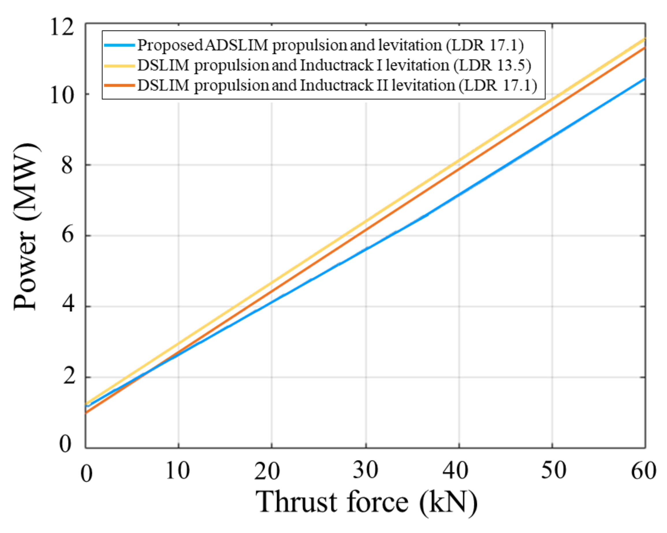
The power consumption graphs versus thrust force for each system are shown in
Figure 13. The advantage of the Inductrack is that the PMs do not consume power to create the magnetic field sustaining the levitation while for the ADSLIM in DC mode, additional power is required to maintain the magnetic field. This advantage is seen in the range of low thrust forces (below 6.85 kN) where “DSLIM Inductrack II” consumes less power than the proposed ADSLIM-based system. However, it is seen from these results that the proposed system consumes less power for operating points above 6.85 kN compared to “DSLIM Inductrack II” and over the whole operating range compared to “DSLIM Inductrack I”.
Table 4 compares the power consumption at zero propulsion, in which all power is solely consumed to sustain levitation and at maximum propulsion of 60 kN. During zero propulsion operation, the proposed ADSLIM-based system consumes roughly 5% less power than “DSLIM Inductrack I” and 21% more power than “DSLIM Inductrack II”. However, it should be noted that the Hyperloop vehicle rarely operates with zero propulsion since even residual pressure in the tube will create some aerodynamic drag. For the operating regime with the maximum propulsion of 60 kN, the proposed system consumes 10% less power than “DSLIM Inductrack I” and 8% less power than “DSLIM Inductrack II”.
Overall, the obtained results represent a fair comparison of the power consumption associated with sustaining levitation since all three systems are compared under the same operating conditions and are considered to have identical propulsion system efficiency. These results show that the proposed system demonstrates lower power consumption compared to both Inductrack maglev systems in the propulsion range of 6.85–60 kN, which covers almost 89% of the operating range.
7. Conclusions
A novel method of combined propulsion and levitation control for ADSLIMs utilizing a combination of AC and DC modes of operation is proposed for maglev/Hyperloop transportation which offers a high level of controllability, high efficiency and low complexity. It was shown that a combination of AC and DC current modes can simultaneously control the thrust and lift forces of a group of ADSLIMs while addressing their limitation in generating the required lift force when operating with low thrust force.
Comparison of power consumption between the proposed ADSLIM-based maglev system and PM-based passive maglev systems showed more efficient operation over the entire operating range when compared to Inductrack I. Compared to Inductrack II, the proposed system used less power over 89% of the operating range. Unlike Inductrack maglev systems, the proposed maglev system does not require PMs or a separate levitation system and utilizes the same LIMs for both levitation and propulsion which has the advantage of reducing the cost and weight of maglev/Hyperloop vehicles. Furthermore, it provides full control of lift force over the entire operating range, which allows compensation for variations in passenger loading.


 ,
, 


