1. Introduction
Due to the advantages of small size, high power density, and simple structure, etc., brushless DC motors (BLDCM) are widely used in aerospace, household appliances, electric vehicles, and other fields [
1,
2,
3,
4,
5]. However, during the operation of the motor, vibration and noise are generated due to the commutation torque ripple, which restricts the application of the motor in the high-performance field [
6,
7,
8].
A series of studies have been conducted, by a wide range of scholars, to address the commutation torque ripple of BLDCM. In [
9], the commutation torque ripple is analyzed and researched, and it is noted that the commutation torque ripple can be suppressed by maintaining a smooth non-commutation phase current. In [
10], the PWM period during the commutation of the motor is divided into three parts, and, by adjusting the appropriate ratio of these three parts, the commutation torque ripple can be suppressed during each modulation period. In [
11], a full-order Romberg observer is designed to estimate the opposite potential, optimize the reference phase current during motor operation, and use two-phase and three-phase conduction modes, switching control during commutation, in which the commutation torque ripple is reduced. A hybrid switching method is proposed in [
12]; the motor is controlled by two-phase and three-phase conduction modes during the non-commutation and commutation periods, and the voltage compensation method is combined during the commutation period to suppress the commutation torque ripple.
The above strategies have a significant suppression effect on the commutation torque ripple, but the control mode needs to be changed frequently. In [
13], a finite set model prediction strategy for commutation torque ripple suppression is proposed. A discrete time non-commutation current prediction model is established during the commutation period, and the optimal switching state for the next control cycle is judged according to the value function. In [
14], a main and auxiliary vector table is designed, adopted, and a unified vector selection strategy is applied to the non-commutation and commutation periods of the motor; the commutation torque ripple is suppressed by the joint action of the main and auxiliary vectors in each control cycle.
During the operation of the motor, the control strategy does not need to switch between the above two strategies. However, when the motor is running in the high speed range, it is limited by the DC side voltage of the inverter and cannot effectively suppress the commutation torque ripple in the full speed range.
In this regard, a control strategy, adding a DC-DC converter at the front end of the inverter, has been proposed to provide a higher voltage to the BLDCM by adjusting the DC bus voltage during commutation, thereby solving the commutation torque in the full speed range [
15]. In [
16], the SEPIC converter is used to increase the DC link voltage during the commutation period, and the switch selection circuit is used to select the DC power supply in order to provide energy for the motor during the non-commutation period. In [
17], the commutation torque ripple can be reduced by adjusting the Z-source inverter through vector and the effective vector duty cycle. This strategy can also use a DC power supply which is lower than the rated voltage of the motor to improve the utilization rate of the power supply voltage. In [
18], the inverter input voltage is changed by two working modes of the Cuk converter; the boost mode is used to keep the non-commutated phase current stable during the commutation period. The PAM method is applied during the normal conduction period of the inverter in order to reduce the voltage spike damage caused by the PWM to the motor.
A single-input dual-output (SIDO) Cuk converter is proposed in [
17]. Compared with the traditional two independent Cuk converters, this converter has excellent interleaved control, and it greatly reduces the number of components. To control the power switch in the SIDO Cuk converter, two different voltage values can be output at the same time in a modulation period, and one output voltage is always greater than the other output, which provides a new idea for suppressing commutation torque ripple.
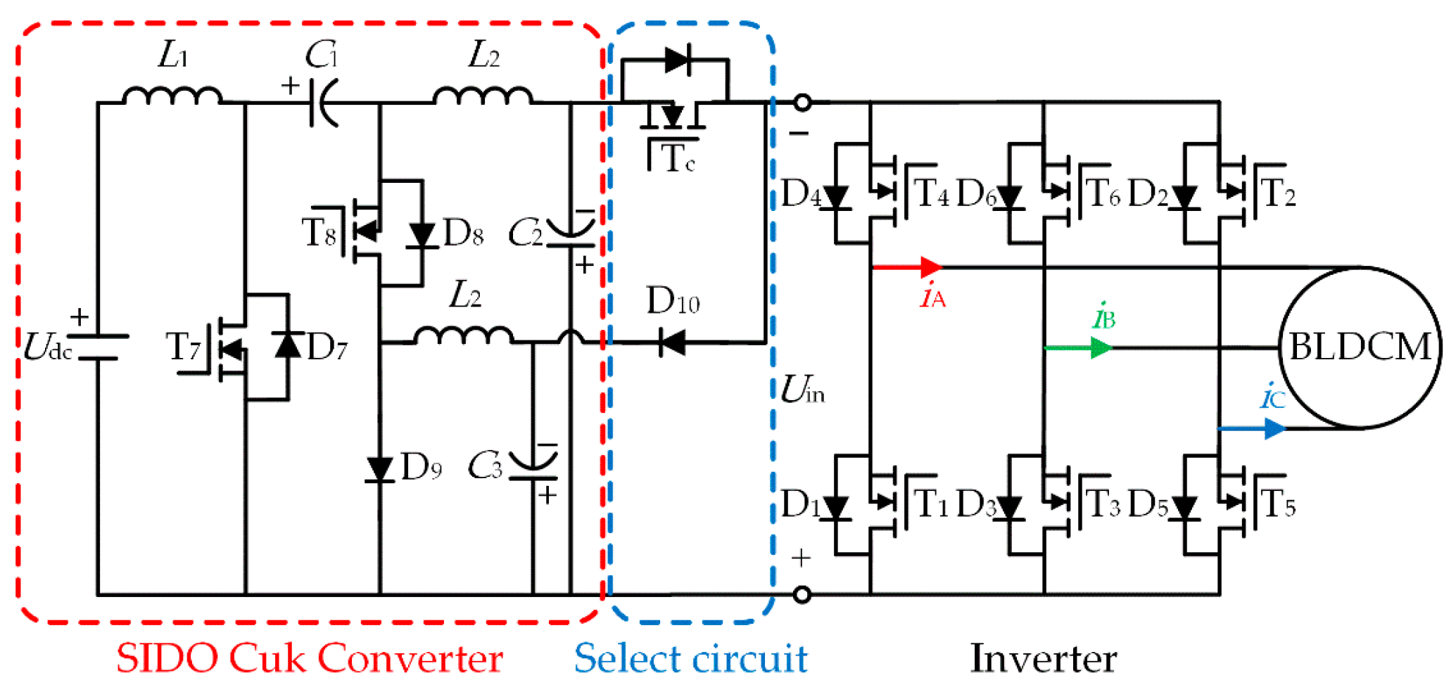
A novel BLDCM commutation torque ripple suppression strategy, based on the SIDO Cuk converter, is proposed in this paper. A unified control method is adopted by this strategy in order to suppress the commutation torque ripple in the full speed range. The lower and higher voltage outputs of the SIDO Cuk converter are used to provide energy to the motor during the non-commutation and commutation periods, respectively. The inverter is controlled using only the PAM method to minimize voltage spike damage to the motor. For industrial applications with lower DC power supply voltage, the power supply voltage utilization rate can be improved by using the two output voltages of the SIDO Cuk converter.
3. The Voltage Scalar Construction at the Output of the SIDO Cuk Converter Regulator Circuit
This section will combine the SIDO Cuk converter, described in the previous section, and the BLDCM operation principle in order to design the voltage scalar that enables the motor to run smoothly.
The voltage scalars
Vm1 and
Vm2 are constructed for the on-state of the power switch T
c and diode D
10 in the selection circuit in
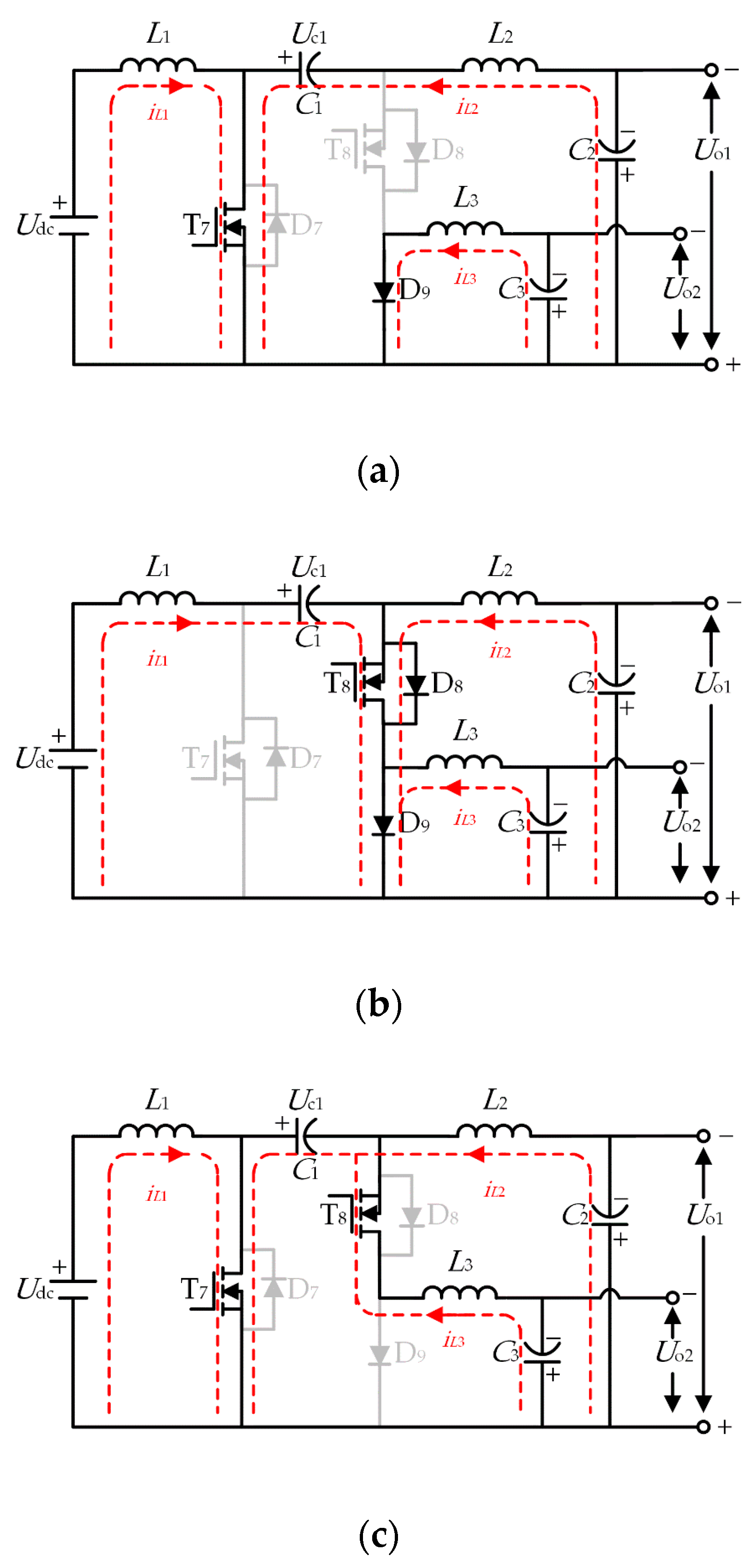
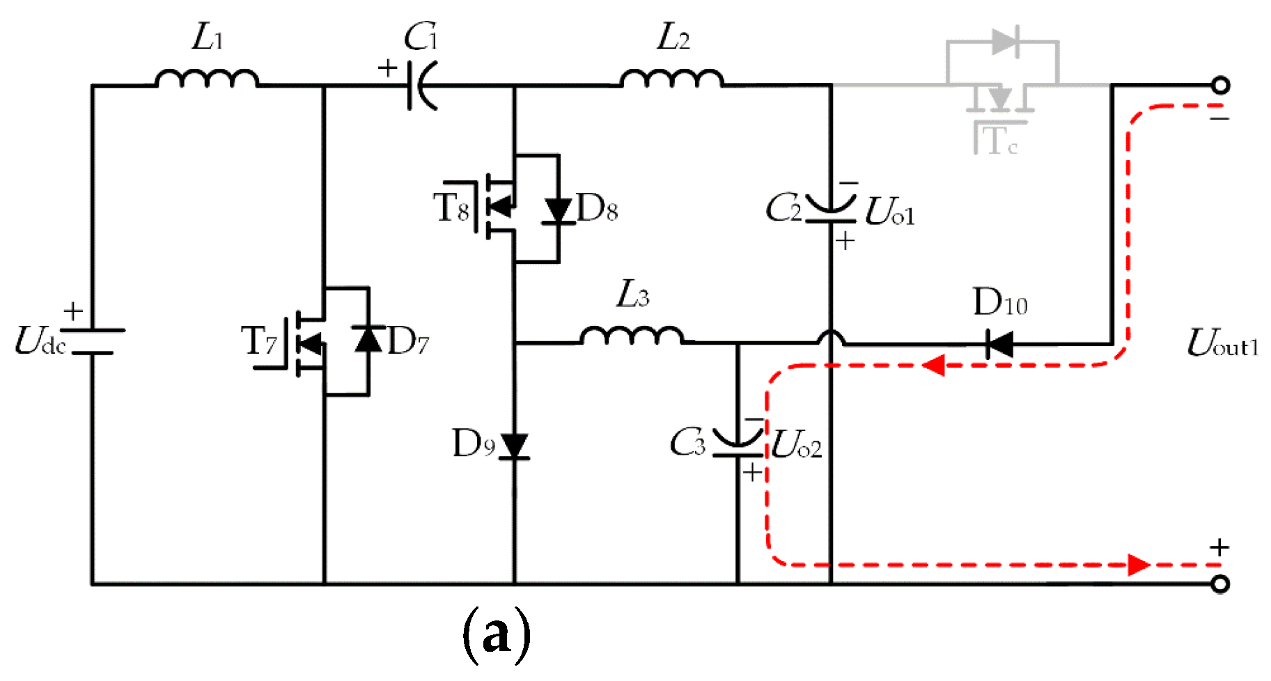
Figure 5. The equivalent circuits for the different voltage scalars are shown in
Figure 5.
Vm1: As shown in
Figure 5a, T
c is turned on, D
10 is reversely cut off, the output of the SIDO Cuk converter
C3 is used as the overall output of the voltage regulating circuit, and, at this time,
C3 is used alone for the motor power supply; the inverter input voltage to meet
Uin =
Uout1 =
Uo2.
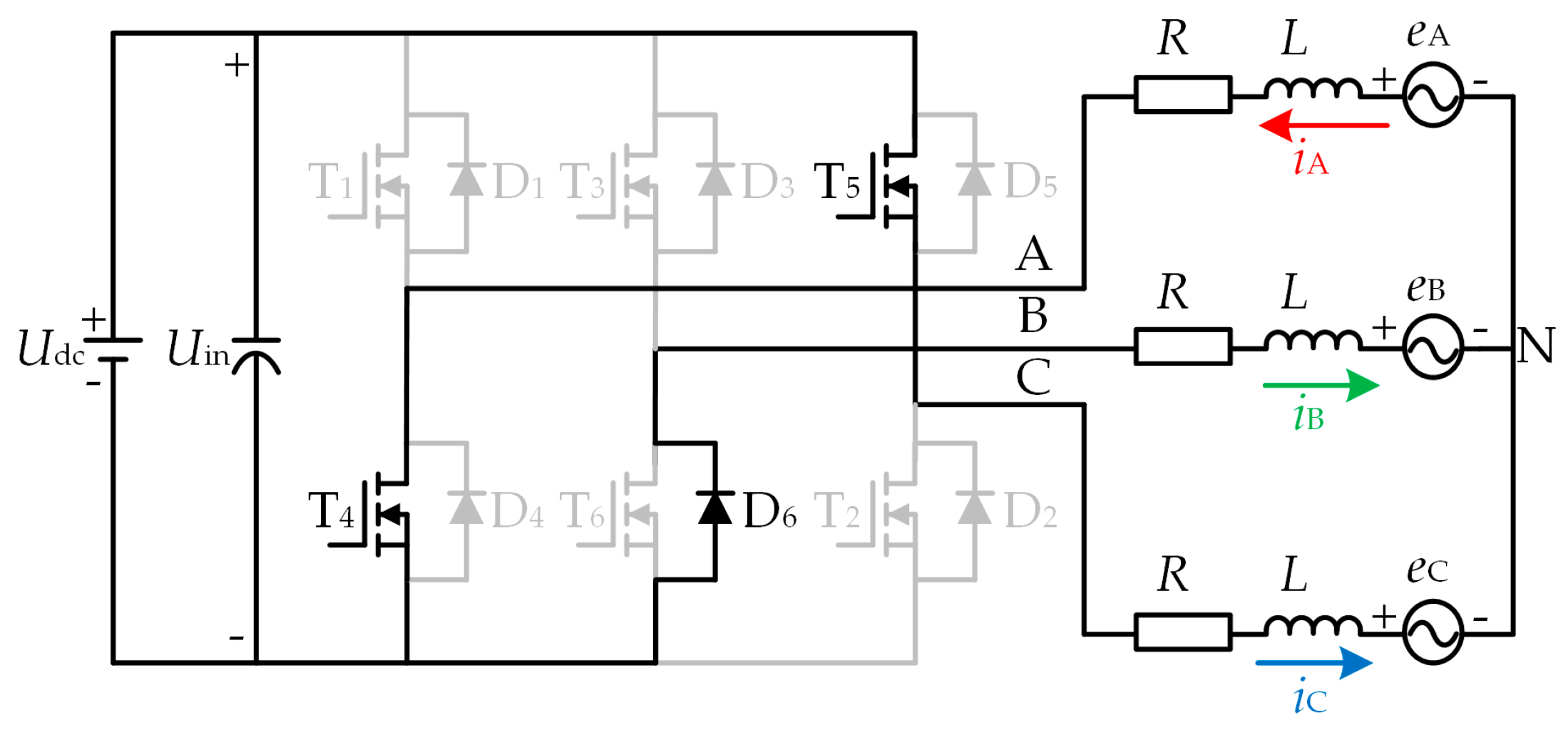
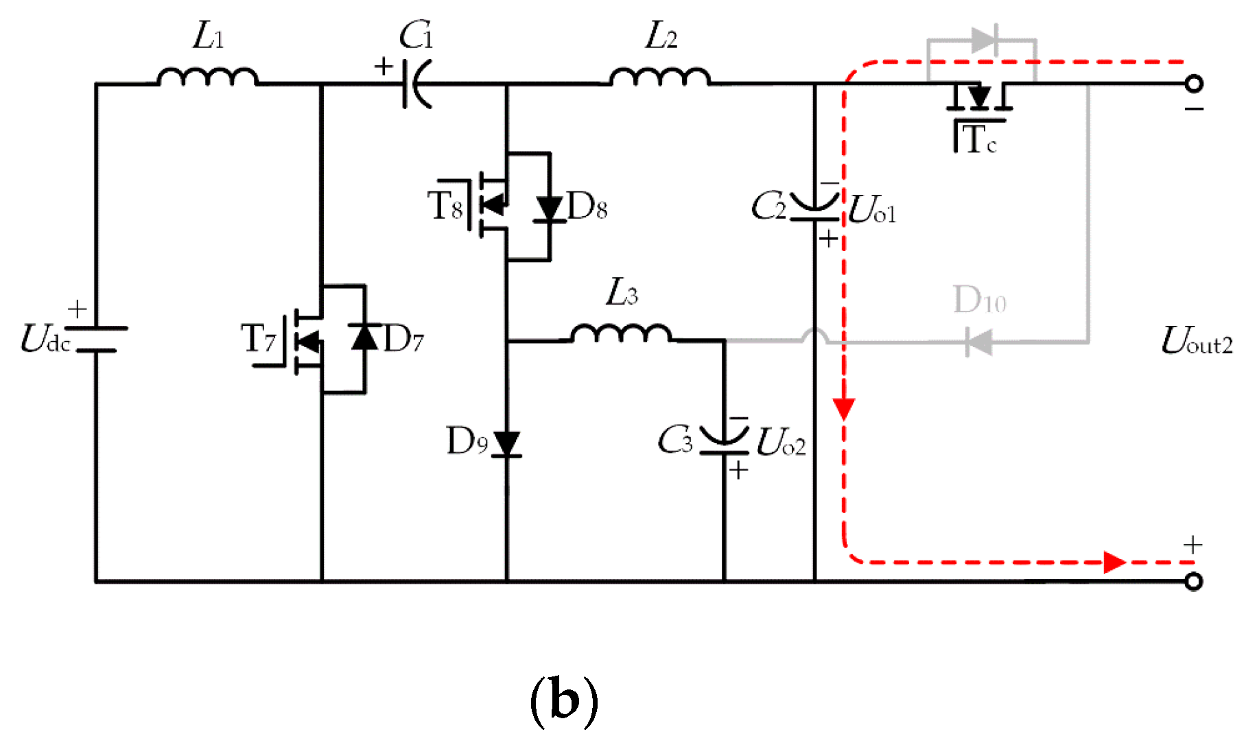
Vm2: As shown in
Figure 5b, T
c is turned off, D
10 is turned on, the output of the SIDO Cuk converter
C2 is used as the overall output of the voltage regulating circuit, and, at this time,
C2 is used alone for the motor power supply; the inverter input voltage to meet
Uin =
Uout2 =
Uo1.
According to Kirchhoff’s law, the input voltage of the inverter with different voltage scalars is expressed as
Through the above analysis, the inverter will select different input voltage values when the power switch Tc is in different switching states, especially when Tc is turned on, Uo1 > Udc is always satisfied by Vm2, which can maintain the input voltage of the inverter Uin = 4E + 3RI during the commutation period of the motor running in the high-speed range, and thus suppress the commutation torque ripple.
4. The Proposed Method of Suppressing the Commutation Torque Ripple
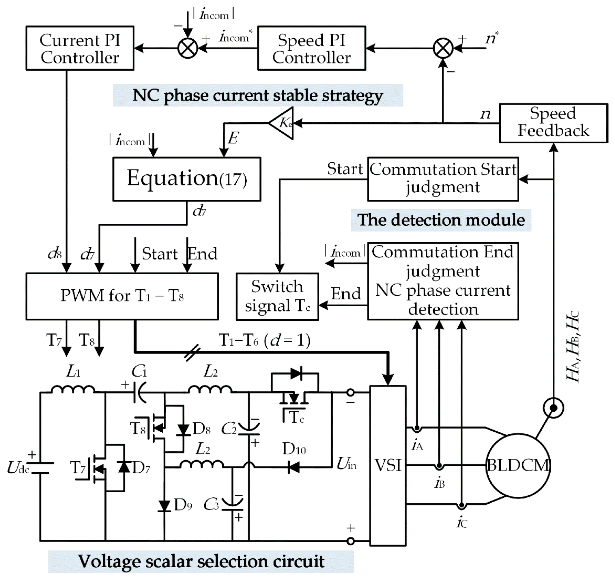
The energy of the BLDCM operation during the non-commutation and commutation periods is provided by two different output voltages of the SIDO Cuk converter in order to reduce the commutation torque ripple. In this paper, the proposed commutation torque ripple reduction strategy shown in
Figure 6 is designed. The control unit includes the voltage scalar selection circuit, the non-commutation (NC) phase current stable strategy, and the detection module. The voltage scalar selection circuit is designed to switch the different output voltages of the SIDO Cuk converter. A higher output voltage is selected during the commutation period in order to increase the input voltage of the inverter. During the non-commutation period, the lower voltage regulation of the SIDO Cuk converter is realized through the speed and current PI controller in order to meet the speed regulation requirements of the motor. The reference speed
n* is given by the host computer, and the output of the speed PI controller is the reference current
i*. The NC phase current stable strategy is adopted in order to realize higher voltage regulation of the SIDO Cuk converter, maintain the stability of the NC phase current, and suppress the commutation torque ripple. The signals (
iA,
iB,
iC and
HA,
HB,
HC) of the sensor are collected by the detection module in order to judge the start and end signals of the commutation period and detect the NC phase current value.
The speed adjustment of the motor can be achieved by chopping the inverter or controlling the PAM method. Compared with the traditional ON-PWM modulation method, the proposed method uses the PAM method to control the inverter during both the commutation period and the non-commutation period. It can minimize the voltage spikes and current ripples generated by PWM modulation.
4.1. The Control Strategy during the Commutation Period
During the commutation process, due to the existence of the winding inductance, the phase current cannot be changed abruptly, and, as a result, this stage is called the commutation period of the BLDCM. In order to suppress the commutation torque ripple, it can be observed from Equation (14) that Uin ≥ 4E + 3RI is satisfied during the commutation period, and the non-commutation current is stabilized.
In the control strategy proposed in this paper, the PAM method is used to control the inverter. When the transition edge (rising edge, falling edge) of the Hall signal (
HA,
HB,
HC) is detected, the commutation process is started. In order to inhibit the commutation torque ripple, T
c is turned on and the voltage scalar
Vm2 is selected as the inverter input voltage, as shown in
Figure 5b, and, at this time, the duty cycle during commutation in Equation (14) satisfies
dcom = 1; it can be observed that
Vm2 is satisfied
Since the output
Uo1 of the SIDO Cuk converter is the same as that of the traditional Cuk converter, and the output is controlled by the power switchT
7, substituting (16) into (4) the second equation, the duty cycle of T
7 can be obtained as
When it is detected that the outgoing current becomes zero during the commutation process, the commutation process is ended, the T
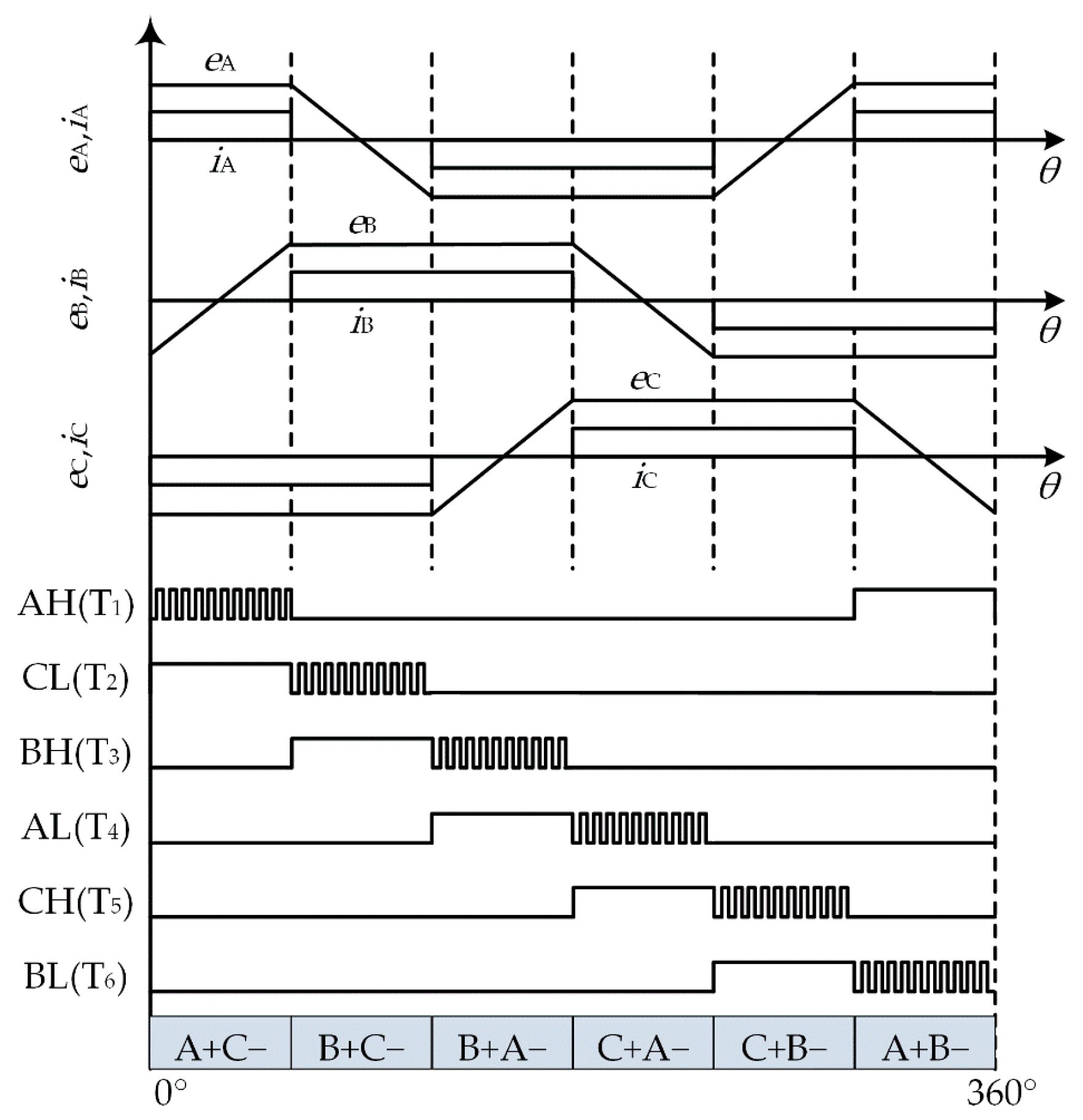
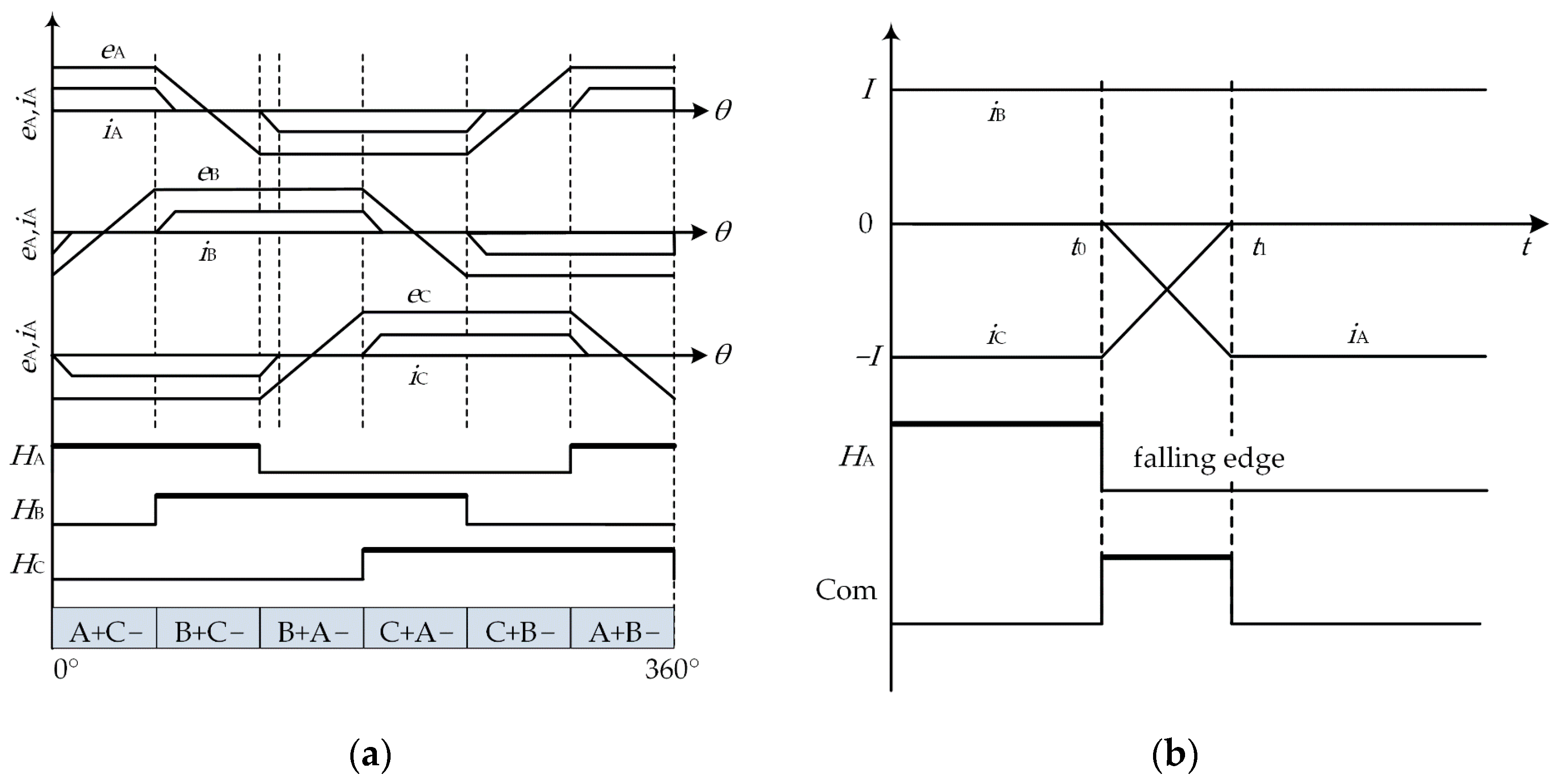
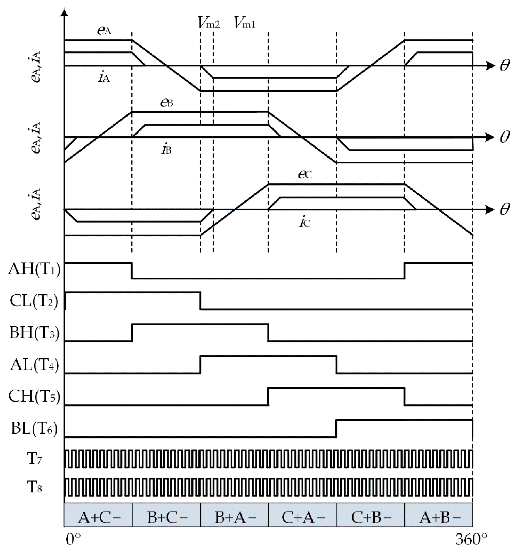
c is turned off, and the control strategy during the non-commutation period is entered. The corresponding relationship between back EMFs, phase current, and Hall signal is shown in
Figure 7. The Hall signal’s (
HA,
HB,
HC) and the commutation signal’s (Com) high levels are drawn by bold lines. As shown in
Figure 7a, according to the transition edge (rising edge, falling edge) of the Hall signal (
HA,
HB,
HC), a 360° electrical cycle can be divided into six commutation cycles. Observing the B + C − to B + A − commutation process of the Hall signal (
HA) transition as an example, the detailed commutation process is shown in
Figure 7b. At time
t0, the transition edge signal (falling edge) of
HA is detected, and the commutation process is started; during the period from
t0 to
t1,
iA increases from 0 to −
I, and
iC decreases from −
I to 0; at time
t1, it is detected that
iC becomes 0, and the commutation process is ended.
4.2. The Control Strategy during the Non-Commutation Period
During the non-commutation period, in order to prevent the inverter control mode from being changed, the PAM mode control is still adopted. For the speed regulation performance of the motor to be satisfied, as shown in
Figure 5a, T
c is turned off, and the voltage scalar
Vm1 is selected as the inverter input voltage. It is known from Equation (8) that
Uin = 2
E + 2
RI, that is,
Vm1 is expressed as
Since the output
Uo2 of the SIDO Cuk converter is controlled by the power switches T
7 and T
8, substituting (18), (17) into (4) the third formula, the duty ratio of T
8 can be obtained as
The modulation method of the proposed commutation torque ripple suppression strategy is shown in
Figure 8.
When the motor is running during the non-commutation period, T
c is turned off. The voltage scalar
Vm1 is selected as the inverter input voltage, and the power switch T
8 in the SIDO Cuk converter is adjusted by a speed and current PI controller to meet the motor speed regulation requirements. The detailed control method is shown in
Figure 6. When the motor is running during the commutation period, T
c is turned on. The voltage scalar
Vm2 is selected as the inverter input voltage, and the non-commutation current stabilization strategy is adopted to adjust the power switch T
7 in the SIDO Cuk converter in order to meet the voltage demand during the commutation period. The inverter is only controlled by PAM mode, and it only performs the role of electronic commutation.
5. Experimental Results and Analysis
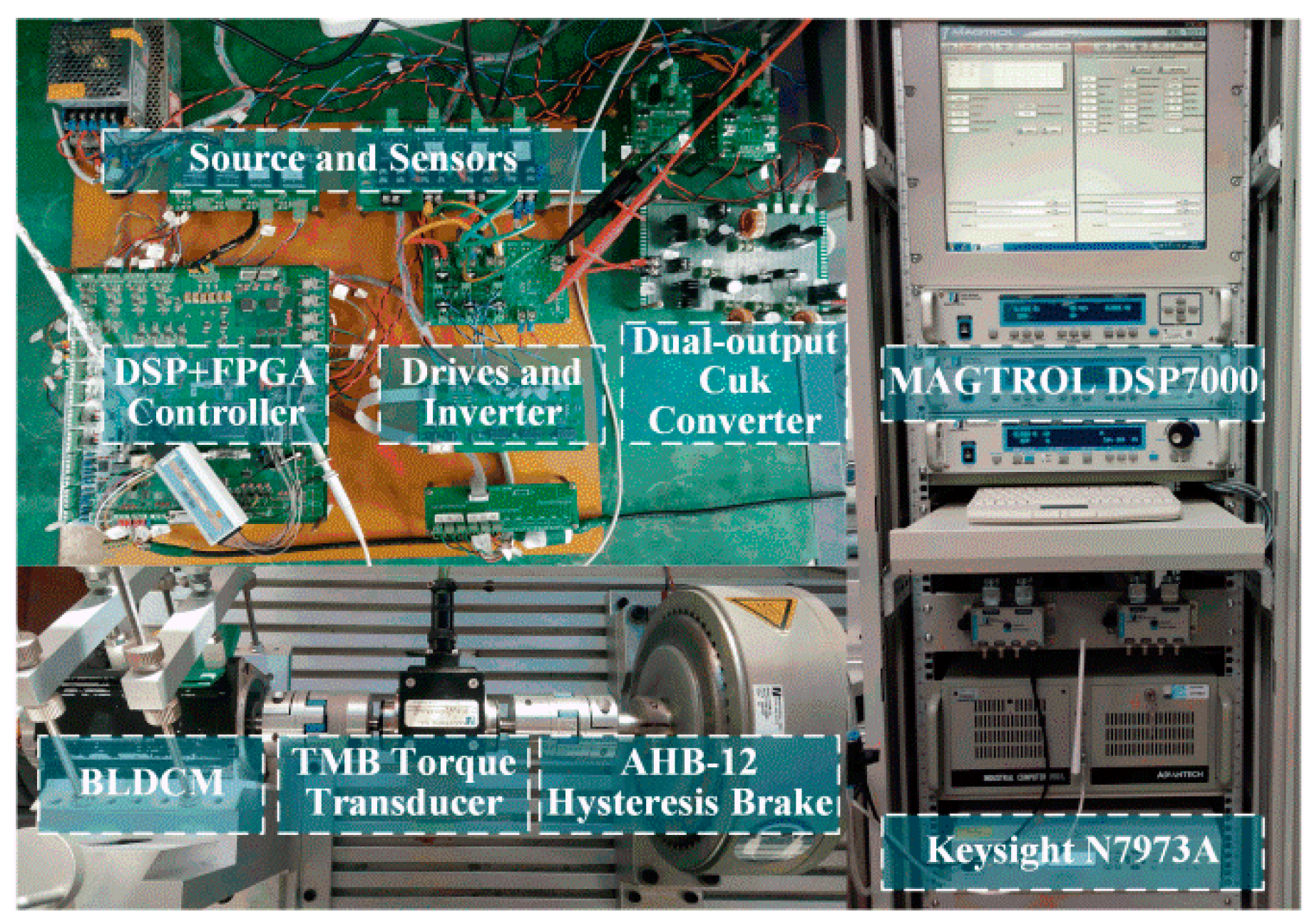
In order to verify the validity of the theoretical analysis and the effectiveness of the proposed strategy, an experimental system, as shown in
Figure 9, was established.
The experimental system was built based on DSP and FPGA. The BLDCM phase current is measured by CSM025A. The basic parameters of the experimental motor are listed in
Table 1. The parameters of the SIDO Cuk converter are selected by the method in [
19]. The values of capacitors
C1−
C3 are 1000μF, 670μF, and 1000μF, respectively, and the values of inductors
L1−
L3 both use 330μH. The DC voltage is provided by the Keysight N7973A DC power supply. The load is provided by the MAGTROL motor test system. The experimental results are recorded by a Yokogawa DLM4058 digital oscilloscope, and the inverter switching signals and SIDO Cuk converter drive signals T
7 and T
8 are obtained through the logic probe PBL100.
According to section 3.43 of IEC 60034-20-1, the torque ripple rate
KrT is defined as
where,
Thigh and
Tlow are the maximum and minimum torque values in a given period of time.
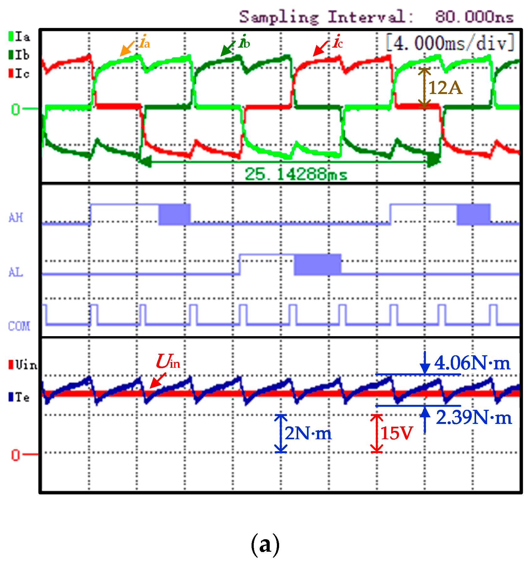
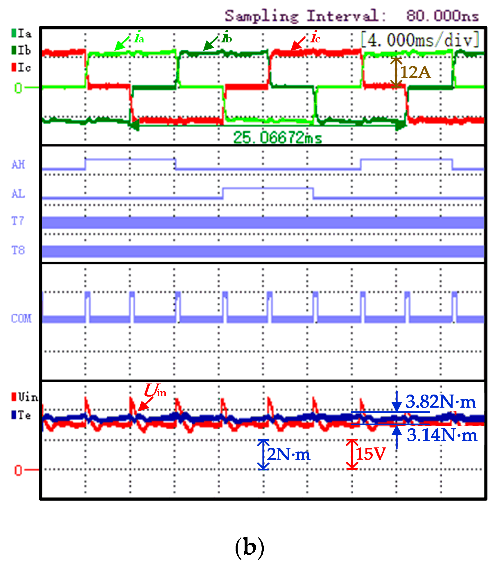
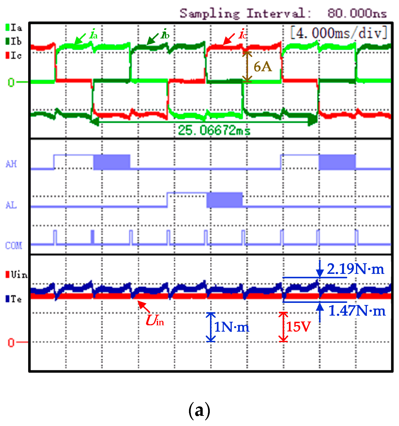
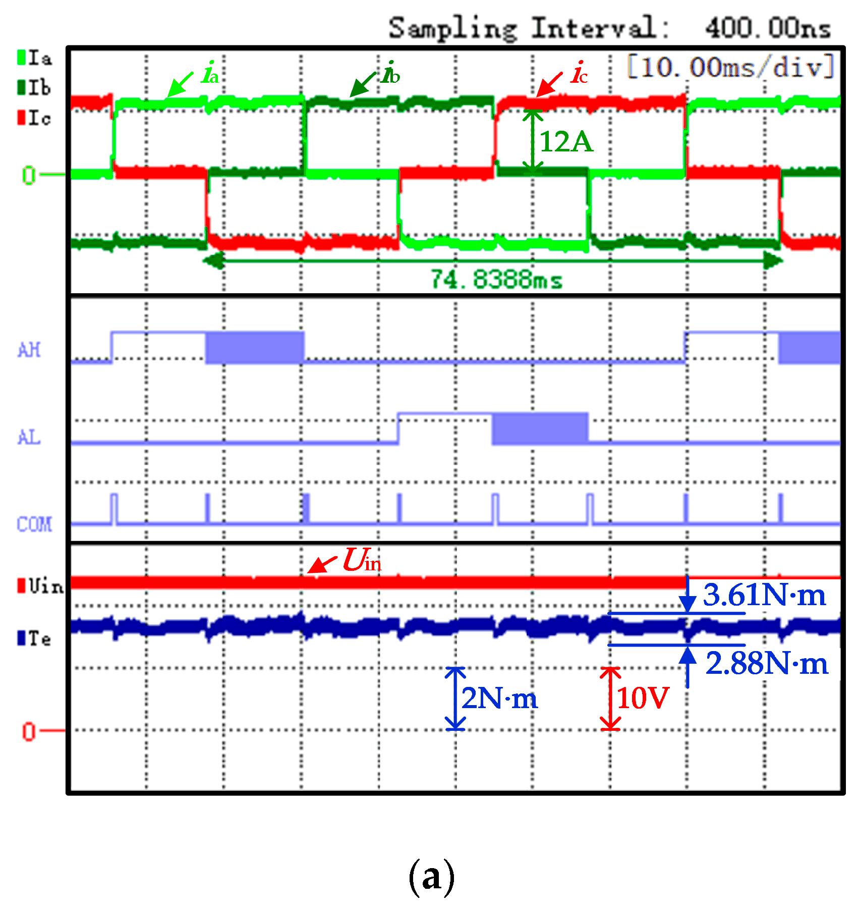
The comparison is made based on the ON-PWM modulation strategy of the double closed loop of the speed and current. In the experiment, the DC power supply voltages of the traditional and proposed strategies are set to 24V and 22V, respectively. Experiments are carried out under rated condition (
n* = 600 r/min,
TL = 3.2 N·m). The experimental results of the two strategies are shown in
Figure 10a,b.
The traditional strategy experiment waveform, shown in
Figure 10a, is represented from top to bottom as three phase currents (
iA,
iB, and
iC), A-phase PWM signal (AH is the upper arm, AL is the bridge arm), the commutation signal "COM", the input voltage of the inverter (
Uin), and electromagnetic torque (
Te). The power supply voltage satisfies
Udc =
uN = 24 V; it can be observed that the non-commutated phase current has obvious ripples with
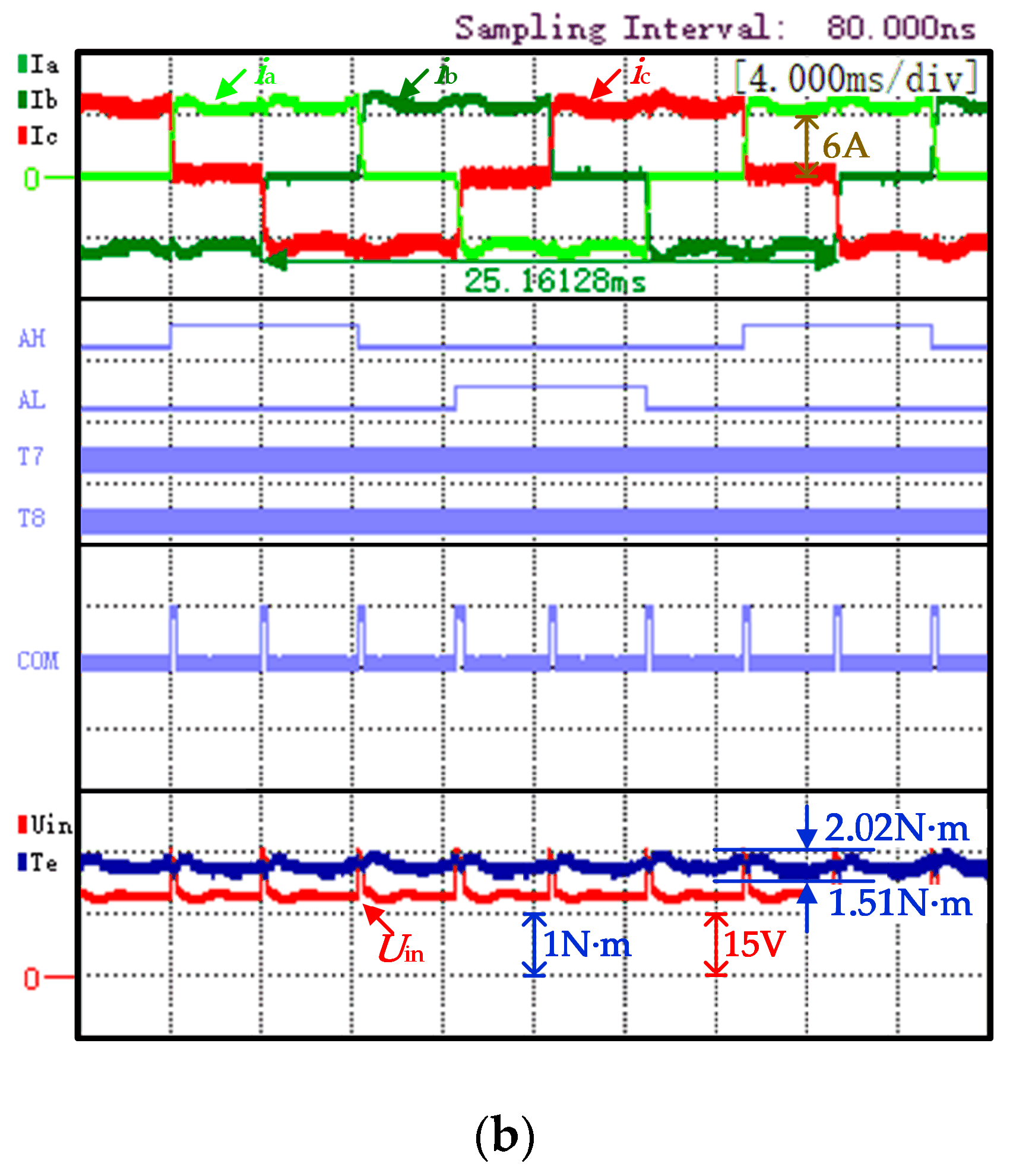
KrT being 25.4%. The proposed strategy experiment waveform is shown in
Figure 10b. At this time, the power supply voltage
Udc = 22 V; it can be observed that the torque ripple is significantly reduced with
KrT being 9.8%.
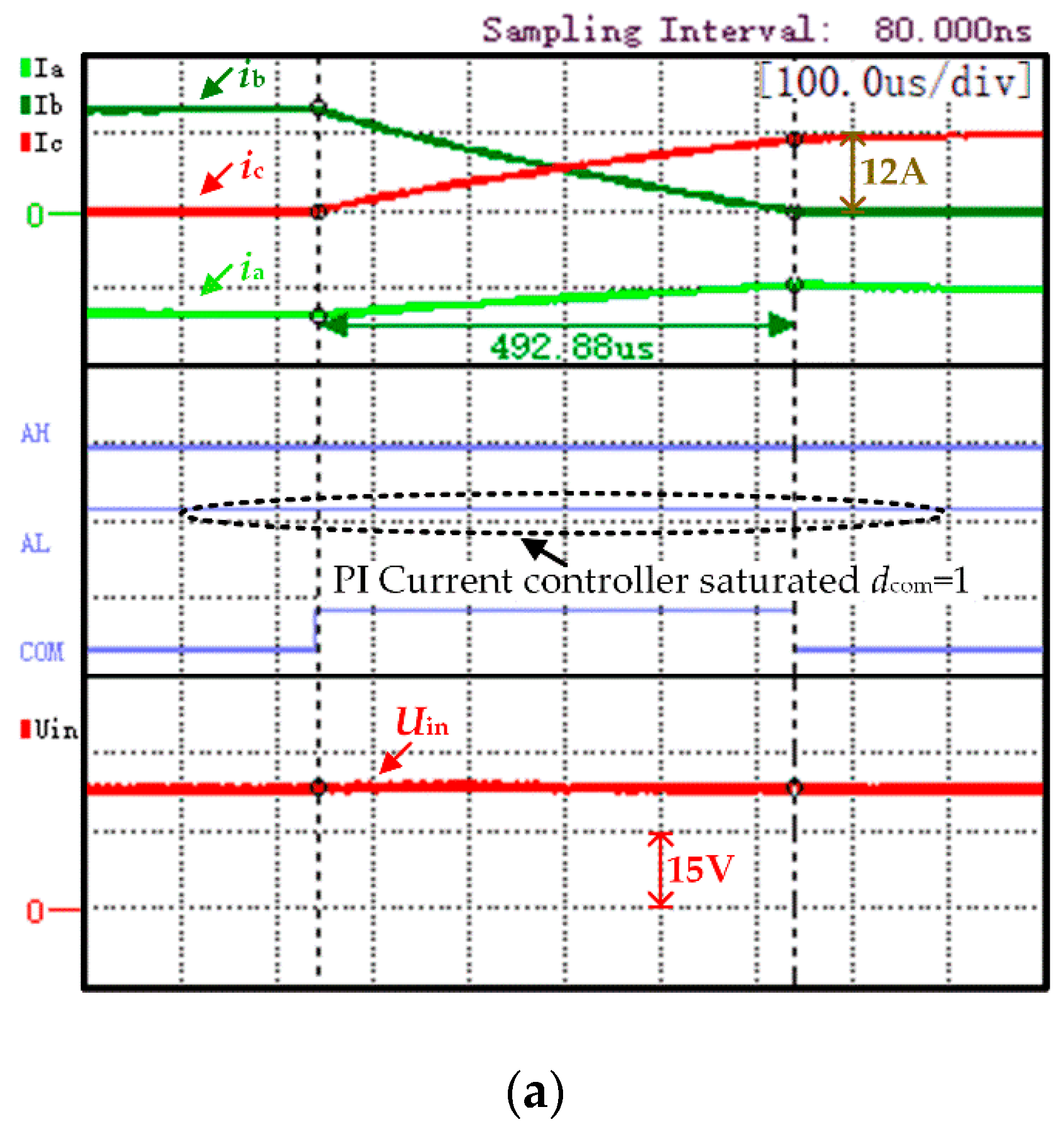
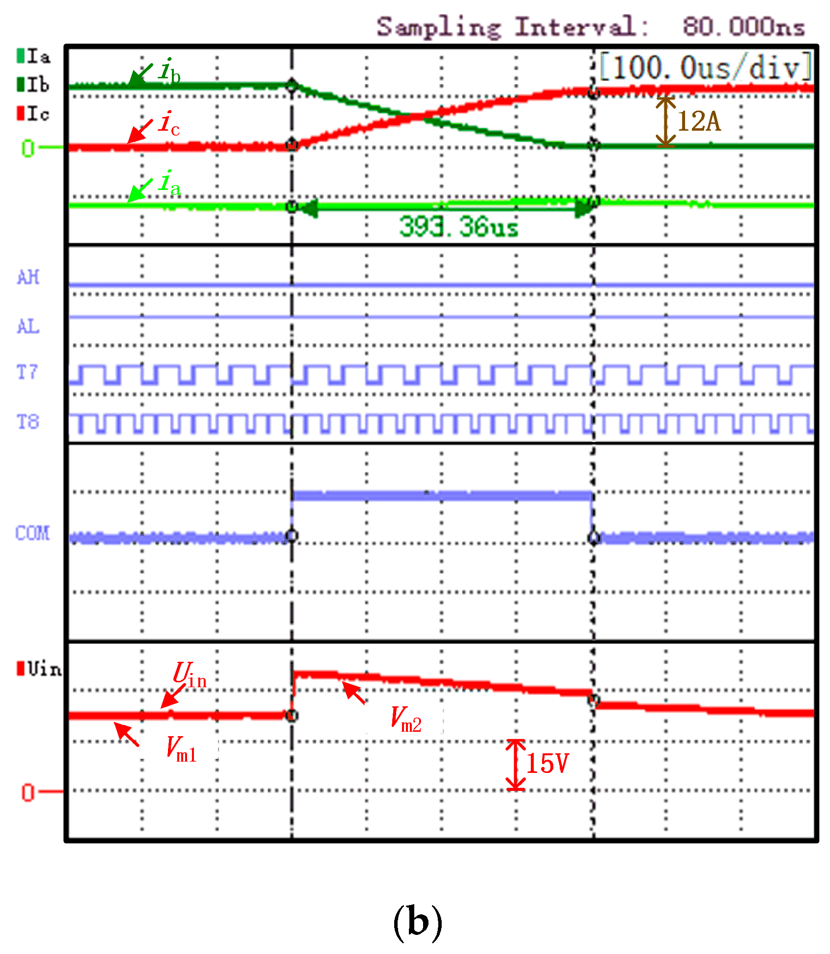
Figure 11a,b are enlarged views of
Figure 10a,b, respectively, during the B + A − → C + A − commutation period, and the waveform definition is the same as that of
Figure 10.
From the commutation period of the traditional strategy shown in
Figure 11a, it can be observed that the power supply voltage of the system is constant, and the output of the current PI controller is saturated. At this time,
dcom = 1, and the non-commutation phase current cannot be kept stable. Under the proposed strategy shown in
Figure 11b, the inverter input voltage has two different values during the non-commutation period and the commutation period. During the non-commutation period, the voltage scalar
Vm1 is selected to meet the motor speed regulation requirements. During the commutation period, the voltage scalar
Vm2 is selected to meet the voltage required to keep the non-commutation current stable.
Experiments are carried out under light load conditions (
n* = 600 r/min,
TL = 1.6 N·m). The experimental results of the two strategies are shown in
Figure 12a,b. The waveform definition of
Figure 12 is the same as that of
Figure 10. The torque ripple rate of the traditional strategy, with
KrT being 19.6%, can be observed in
Figure 12a, and the torque ripple rate of the proposed strategy, with
KrT being 14.4%, can be observed in
Figure 12b.
Experiments are carried out under low speed conditions (
n* = 200 r/min,
TL = 3.2 N·m). The experimental results of the two strategies are shown in
Figure 13a,b. The waveform definition of
Figure 13 is the same as that of
Figure 10. From
Figure 13a,b, it can be observed that the torque ripple
KrT of the traditional strategy and the proposed strategy are 11.2% and 11.0%, respectively. The non-commutated current can be effectively kept stable by the two strategies under low speed condition. Through the above analysis, the commutation torque ripple is effectively suppressed by the proposed strategy, and the inverter is only controlled by the PAM method, which can make the motor phase current smoother.
In order to provide more clarity on the feasibility and effectiveness of the method proposed in this paper, used to suppress the commutation torque ripple, the commutation torque ripple rates in the experiments under different working conditions are summarized, as shown in
Table 2.
It can be observed from
Table 2 that, under the rated operating condition, the
KrT of the proposed strategy is reduced by 15.6% compared with the traditional strategy. Under light load condition, the
KrT of the proposed strategy is reduced by 5.2% compared with the traditional strategy. Under low speed condition, both the proposed strategy and the traditional strategy can effectively reduce the commutation torque ripple. In summary, the commutation torque ripple can be effectively suppressed by the proposed strategy in this paper.
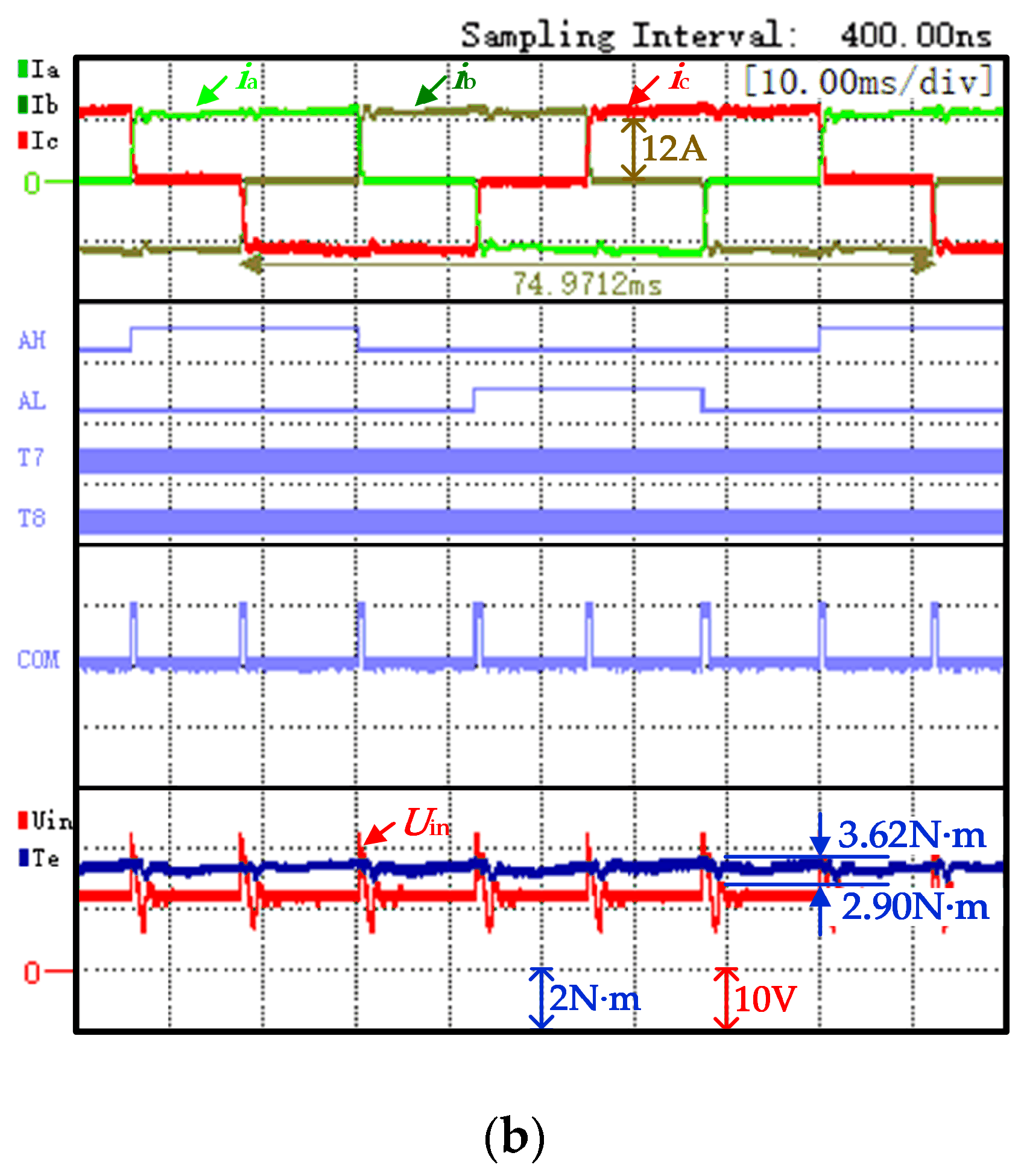
In order to verify the effectiveness of the proposed strategy in dynamic response, information is provided herein. The experimental result of the speed dynamic response with a reference torque of 3.2N·m is shown in
Figure 14.
Figure 14a displays the experimental result of the speed ramping from 200r/min to 600r/min. The partial enlarged view of dynamic response is shown in
Figure 14b. Each waveform, from top to bottom, is the motor speed (
n*,
n), the three phase currents (
iA,
iB and
iC), and the input voltage of the inverter (
Uin). In
Figure 14a, during the acceleration process, the voltage scalars
Vm1 and
Vm2 increase with the increase of the motor speed. In
Figure 14b, it can be observed that the non-commutated current can be stabilized by the proposed strategy during the speed change process.


