1. Introduction
The performance of parts and components has a direct impact on that of machinery and equipment. Advancements in technology and industrial upgrading gave birth to high-performance equipment, which places greater demands on the performance of bearings. Traditional roller bearings, as core parts and components in electro-mechanical systems, have developed a relatively complete research methodology on performance after multiple rounds of iteration and optimization. To obtain bearings with better performance, researchers mainly enhance the performance of roller bearings by technical means such as developing new materials [
1,
2,
3], reinforcing surface treatment [
4,
5,
6], improving machining accuracy, or making structural innovations [
7].
In terms of structural innovation, Tian developed a kind of sliding–rolling compound bearing by combining rolling friction pairs with sliding friction pairs. The bearing has a relatively high rotating speed and improved bearing capacity and impact resistance. Tian et al. also analyzed the bearing performance through finite element analysis and contrast simulation experiments [
8,
9]. Lu conducted a theoretical analysis and fexperimental study on the bearing capacity and contact pattern of sliding–rolling bearings. The results demonstrate that sliding–rolling bearings have excellent heavy-load characteristics and good low-rate start capacity; however, their friction torque is significantly greater than traditional roller bearings [
10]. Afterward, Lu improved the structure of sliding–rolling bearings by replacing solid and hollow rollers with spiral elastic rollers and analyzed the bearing performance through theoretical calculation and finite element simulation. The results show that the modified structure can further improve the bearing capacity of sliding–rolling bearings [
11,
12]. Yao et al. presented an elastic composite cylindrical roller bearing by embedding polytetrafluoroethylene (PTFE) material into a hollow cylindrical roller. This kind of bearing has better capacity against the damage caused by bending fatigue because of the reduced bending stress on the roller’s inner wall, so the dynamic performance of the bearing is superior to that of a solid bearing. When the degree of filling of the roller is 55%, the bearing has the optimum fatigue life; when the degree of filling is 40% or 50%, the maximum amplitude of the bearing is smaller than that of a solid bearing [
13,
14]. Md et al. took dynamic capacity and elasto-hydrodynamic minimum film thickness as objective functions, then carried out multi-objective robust optimization along with design variables of bearing pitch diameter, ball diameter, and the number of rolling elements, which definitely enhanced the performance of the deep-groove ball bearing [
15]. Pavel used a computational model of lubrication and heat transfer to optimize the thrust bearing. The prototype bearing designed using this approach reduced the mechanical losses of the entire turbocharger by approximately 20%; at the same time, there was no significant decrease in the bearing ability [
16].
PTRB is a kind of roller bearing with a new structure [
17]. The author has described its outstanding bearing characteristics in another paper [
17]. Due to its unique structure and operating principle, it has a larger load rating than a ball bearing of equal volume, which has important research value and application prospects. However, there is still room for improvement in its comprehensive performance. Judging from the contact pattern of the roller with the raceway, PTRB belongs to the ball bearing. Meanwhile, given that its unique annular zero-lead thread structure has similarities to the traditional thread connection, the research methodology adopted by researchers on roller bearings [
18,
19,
20,
21] and thread connection [
22,
23,
24,
25] serves as a good reference for the performance analysis of PTRB. However, since PTRB has a novel and complicated structure, theoretical models and structure optimization models specific to the structural characteristics of PTRB should be built based on Hertz contact theory to improve its comprehensive performance further. In addition, a test system is needed to conduct experimental tests on the performance of PTRB.
In
Section 2, preliminary work and PTRB’s structure are briefly introduced. The theoretical models of basic load rating and friction torque are built in
Section 3. In
Section 4 and
Section 5, the PTRB prototype’s performance and the effects of structural parameters on the performance indexes of PTRB are analyzed, respectively. A multi-objective optimization design is conducted on PTRB in
Section 6 to enhance its comprehensive performance further. In
Section 7, a dedicated performance test system is researched and developed to test the friction torque, static bearing capacity, and impact life of the PTRB prototype. Finally, the research results are summarized in
Section 8.
2. Introduction to the Structure
Since the operating principle of PTRB has been described in detail in the author’s previous paper [
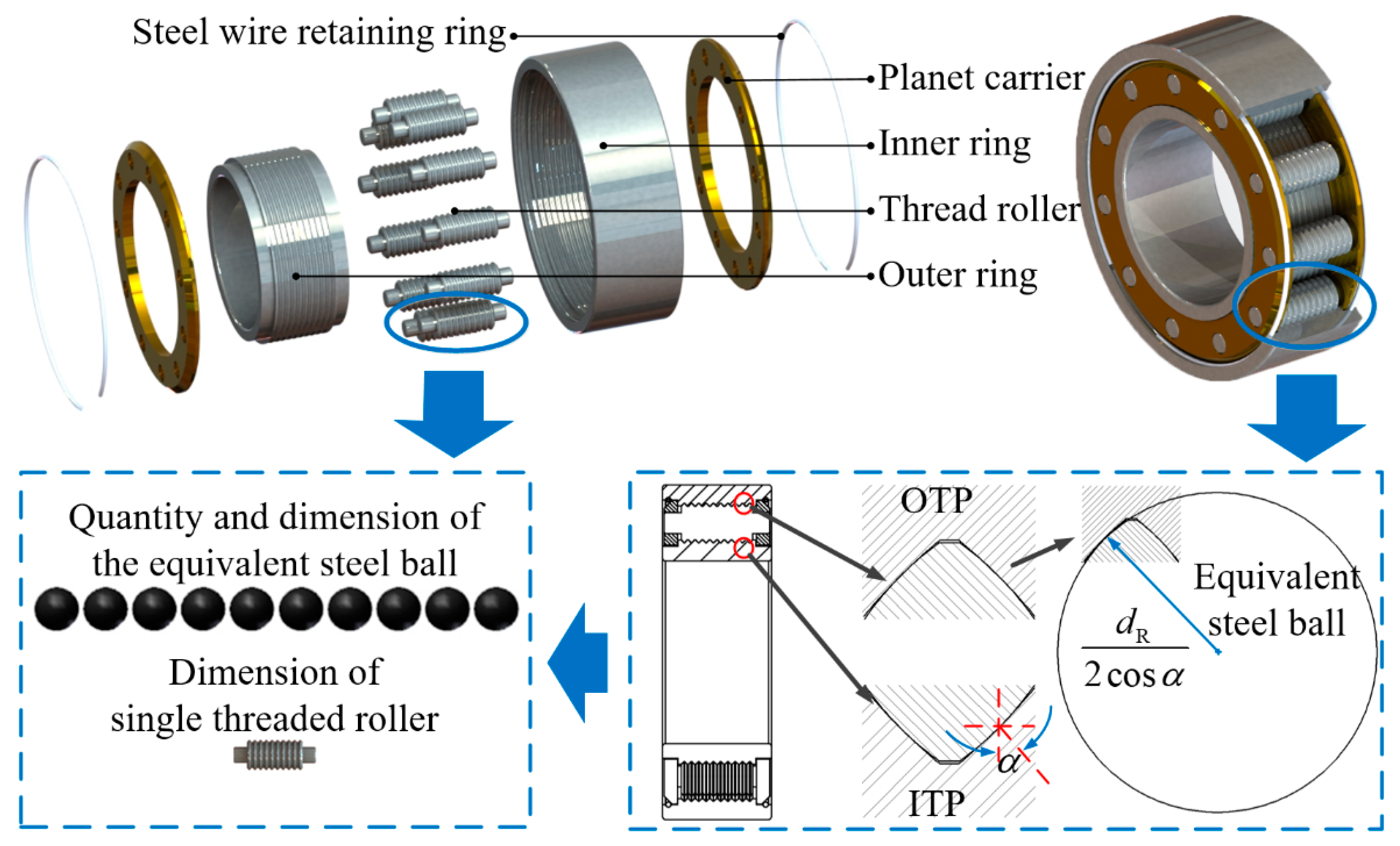
17], this paper only gives a brief introduction. As shown in
Figure 1, PTRB consists of a threaded roller, an inner ring, an outer ring, a planet carrier, and a steel wire retaining ring. Multiple evenly spaced rings of annular threads (zero-lead threads) are machined on the threaded roller, inner ring, and outer ring. The thread teeth of the inner ring and outer ring are in a plane or double-sided arc form, and the threaded roller’s thread teeth are in a double-sided arc form, with an arc radius smaller than the other two. The contact pair formed by mutual contact between the annular thread of the inner ring and that of the threaded roller is defined as an inner ring-threaded roller contact pair (ITP), and the contact pair formed by mutual contact between the annular thread of the outer ring and that of the threaded roller is defined as an outer ring-threaded roller contact pair (OTP). Each contact pair can be regarded as the mutual contact between an equivalent steel ball and a plane or arc surface.
The specific structural parameters of the PTRB prototype studied in this paper are shown in
Table 1. The contact radius of threaded roller
Rrr and the pitch diameter of threaded roller
dR of the PTRB prototype were 5.1 mm and 6 mm, respectively. Each threaded roller was equipped with 10 annular threads. When PTRB was under axial load, each threaded roller could be equivalent to 10 equivalent steel balls with a diameter of
dR/cos
α = 8.5 mm; when PTRB was under radial load, each threaded roller could be equivalent to 20 equivalent steel balls with a diameter of 8.5 mm [
17]. The equivalent steel balls of PTRB outstripped those of an identically sized ball bearing in size and quantity, giving PTRB a higher bearing capacity. That is to say, PTRB was smaller than a normal bearing given the same bearing capacity.
The deformation by force of each main bearing component of PTRB and the calculation method of load distribution have been described in detail in the author’s previous paper [
23]. It was because of Hertz contact deformation, deformation of the thread teeth, and compressive deformation of the shaft that the load might be unevenly distributed when PTRB is under axial load. The axial load distribution coefficients of ITP and OTP were denoted as
fIai and
fOai, and the maximum axial load distribution coefficients of ITP and OTP were denoted as
fIamax and
fOamax, respectively. When PTRB rotated, the position of the threaded roller kept changing, so the loads exerted on the threaded roller at each position of the distribution circle were different in both direction and value. For this reason, the load might be unevenly distributed when PTRB was under radial load as well. The radial load distribution coefficient of PTRB was denoted as
fri, and the maximum radial load distribution coefficient of PTRB was denoted as
frmax [
26,
27].
3. Calculation Models of the Performance Parameters
3.1. Theoretical Model of Basic Static Load Rating
According to the requirements of the static load rating of roller bearings in relevant standards, in most applications, a total permanent deformation amount of 0.0001 times the roller’s diameter is allowed at the center of the contact point, which will not cause harmful effects in the follow-up running of the bearing. Experiments show that all ball bearings other than the self-aligning ball bearing, including PTRB, would generate 4200 MPa stress at the center of the contact point where the maximum load was applied under the impact of the basic static load rating [
28].
According to the Hertz theory, the maximum contact stress of the contact point exists at the contact ellipse center. That is, the contact stress of each contact point of PTRB should satisfy the following conditions:
where
a and
b are the long/short semi-axis length of the contact pair,
Fnimax is the maximum value in the load force of ITP and OTP.
So, the basic static axial load rating of PTRB was [
17]:
where
maX and
mbX is the correlation coefficient of the contact pair, which can be calculated by the contact characteristics. (Σ
ρ)
X is the sum of principal curvatures of ITP or OTP,
Z is the number of threaded rollers,
n the number of thread teeth per roller, and
famax is the maximum axial load distribution coefficient.
E and
u are the elastic modulus and Poisson’s ratio of the threaded roller, inner ring, and outer ring, respectively.
GCr15, through quenching and tempering, was used for the main bearing components of PTRB. The chemical composition of GCr15 is shown in
Table 2.
When PTRB was under axial load, the thread teeth of the annular threads were vulnerable spots. To prevent the rupture of the thread teeth at the roots, the strength of tooth roots should meet appropriate requirements. So, a strength check was conducted on the tooth roots of the annular threads based on the strength checking formula for thread connection:
where
B is the thread bottom thickness,
d is the pitch diameter, and
X can be R, I, or O. The relevant parameters are listed in
Table 1.
The shear strength of the annular thread tooth roots should meet the following formula:
The basic static radial load rating of PTRB was:
where
frmax is the maximum radial load distribution coefficient.
When PTRB was under radial load, each bearing thread tooth carried the same normal load on both sides, which offset the bending moment and shear stress at the thread tooth roots. So, there was no need to check the strength of the thread tooth roots.
3.2. Theoretical Model of Basic Dynamic Load Rating
According to the requirements of the dynamic load rating of roller bearings in relevant standards, when the basic rating life is one million revolutions, the constant axial load carried by the roller bearing is the basic dynamic axial load rating, and the constant radial load is the basic dynamic radial load rating. Based on the theory of the maximum dynamic shear stress, Lundberg G and Palmgren A presented the theoretical formulas for calculating basic dynamic axial load rating
CDa and basic dynamic radial load rating
CDr of single-row ball bearings, which have been included in the ISO standard [
30,
31,
32].
CDa and
CDr of PTRB were:
Dynamic load coefficient
fc was [
32]:
Based on the specific structure and movement relation of PTRB, the relation between structural coefficient
γ and stress number of cycles
β was:
The basic dynamic load rating of
i rows of common ball bearings that carried single-direction load was:
where
CD is the dynamic load rating of the single thread.
When PTRB was under radial load, the calculation method for multiple rows of common ball bearings could be applied. However, when PTRB was under axial load, the load exerted on different contact pairs of the same threaded roller might be unevenly distributed. Therefore, the basic dynamic axial load rating
Ca and the basic dynamic radial load rating
Cr were obtained as follows according to the specific structure of PTRB:
3.3. Theoretical Models of Friction Torque and Operating Efficiency
Besides the basic load rating, friction torque and operating efficiency are also important performance indexes of the bearing. Based on the friction torque generation mechanism and the methods for calculating the friction torque of traditional ball bearings, the author has derived the formulas for calculating friction torque caused by elastic hysteresis
Me, friction torque caused by spin sliding
Ms, friction torque caused by differential sliding
Md, and friction torque caused by viscous resistance of lubricant
Mv in another paper [
17] that are specific to the operating principle and structure of PTRB. Furthermore, in a sound, dynamic balancing state, no additional force was needed from the planet carrier to correct the position of each threaded roller on the circumference when the threaded roller revolved. There was only a small contact force between the two components, so the threaded roller could drive the planet carrier to rotate smoothly through its optical axes on both sides. The sliding friction caused by the planet carrier and the threaded roller was denoted as
Mh [
33].
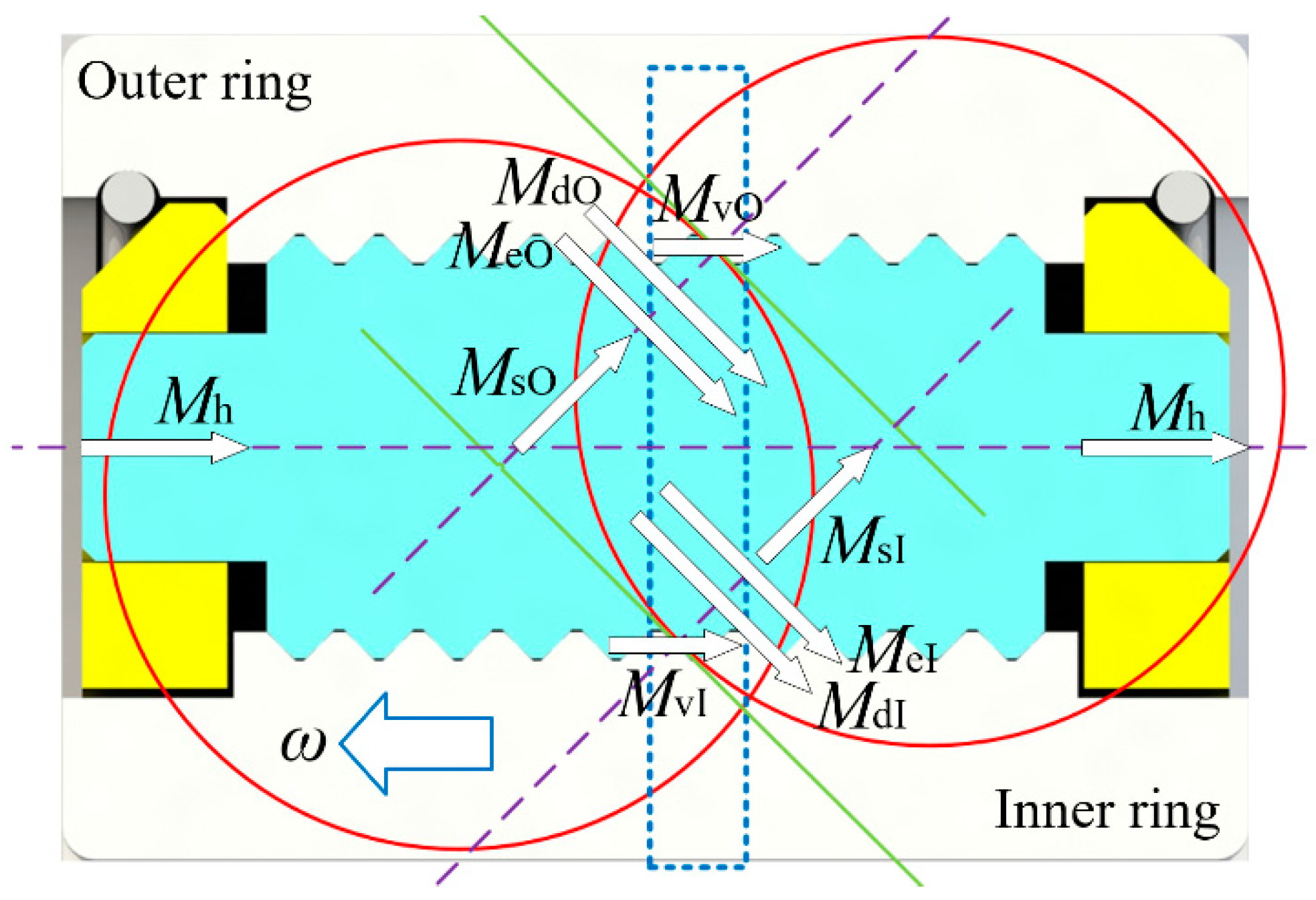
The schematic diagram of each friction torque is shown in
Figure 2. Among all friction torques,
Me,
Ms, and
Ms were determined by the external load, structural performance, and material characteristics;
Mh was determined by the structural performance and bearing speed;
Mv was not only associated with the external load, structural performance, and material characteristics, but also affected by the bearing speed and lubricant type.
In combination with
Figure 2, the friction torques of ITP and OTP, i.e.,
MIi and
MOi, were:
When PTRB was under axial load, the total friction torque
MPTRBa and the friction coefficient
μPTRBa were:
When PTRB was under radial load, the total friction torque
MPTRBr and the friction coefficient
μPTRBr were:
When the torque at the input side was
MD, the operating efficiency of PTRB could be expressed as follows:
4. Analysis of the PTRB Prototype’s Performance
According to Formulas (1)–(13), for the PTRB prototype, C0a and C0r were 38.36 kN and 19.93 kN, while Ca and Cr were 33.20 kN and 30.26 kN.
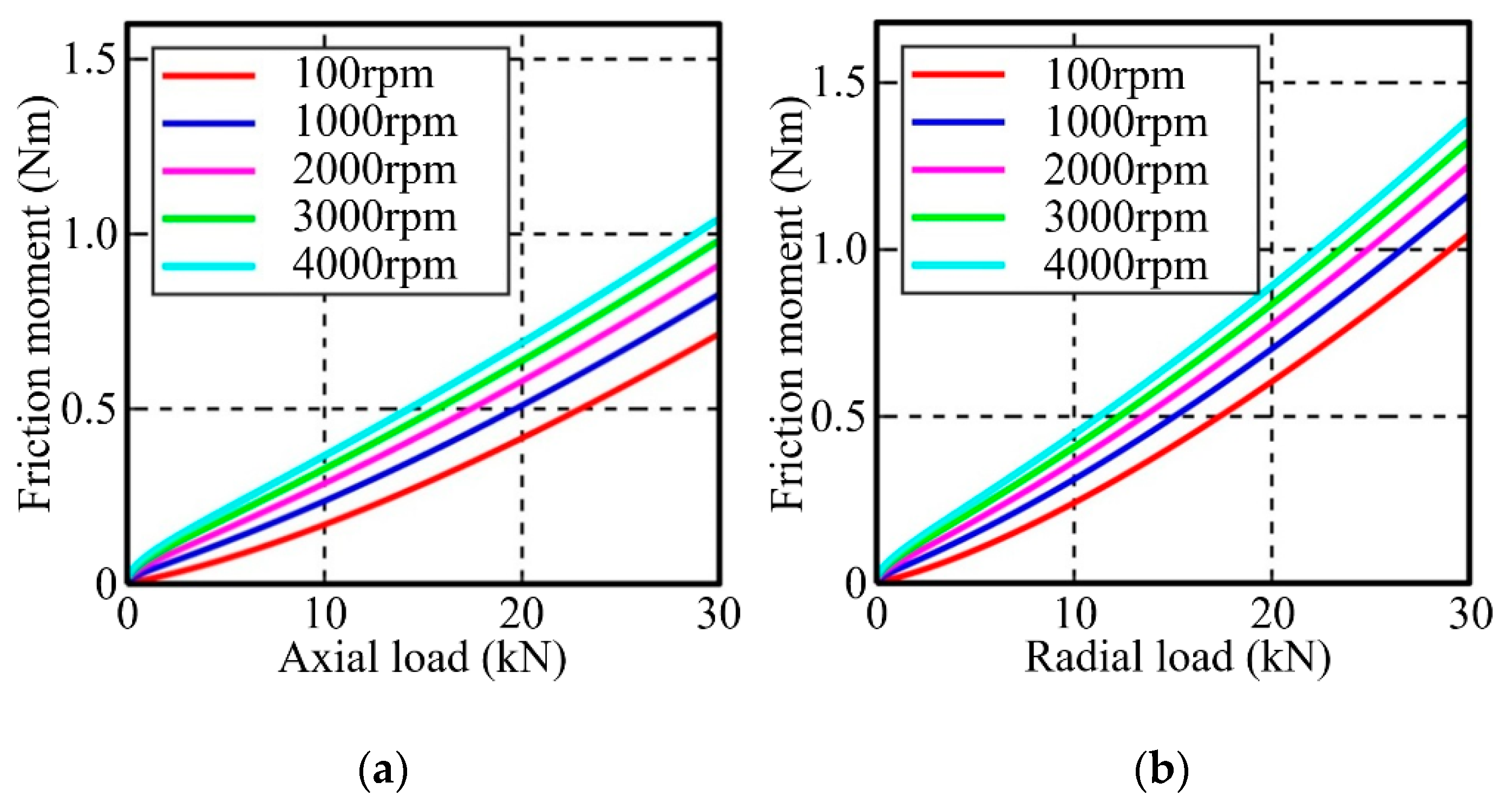
The lubricant chosen for PTRB is lubricating oils for total loss systems L-AN. The pressure–viscosity coefficient is 0.0246 mm
2/N, and the dynamic viscosity under normal pressure is 0.04 MPa•s [
34]. Under an external load of 0–30 kN and a bearing speed of 100–4000 rpm, the variation of friction torque of the PTRB prototype with external load and bearing speed is shown in
Figure 3. The friction torque increased with the increase in external load or bearing speed. Within the range of basic dynamic load rating,
MPTRBa ranged from 0 Nm to 1.045 Nm, and
MPTRBr ranged from 0 Nm to 1.389 Nm. When the external load was 30 kN, with the bearing speed increasing from 100 rpm to 4000 rpm,
MPTRBa increased from 0.715 Nm to 1.045 Nm, and
MPTRBr increased from 1.042 Nm to 1.389 Nm.
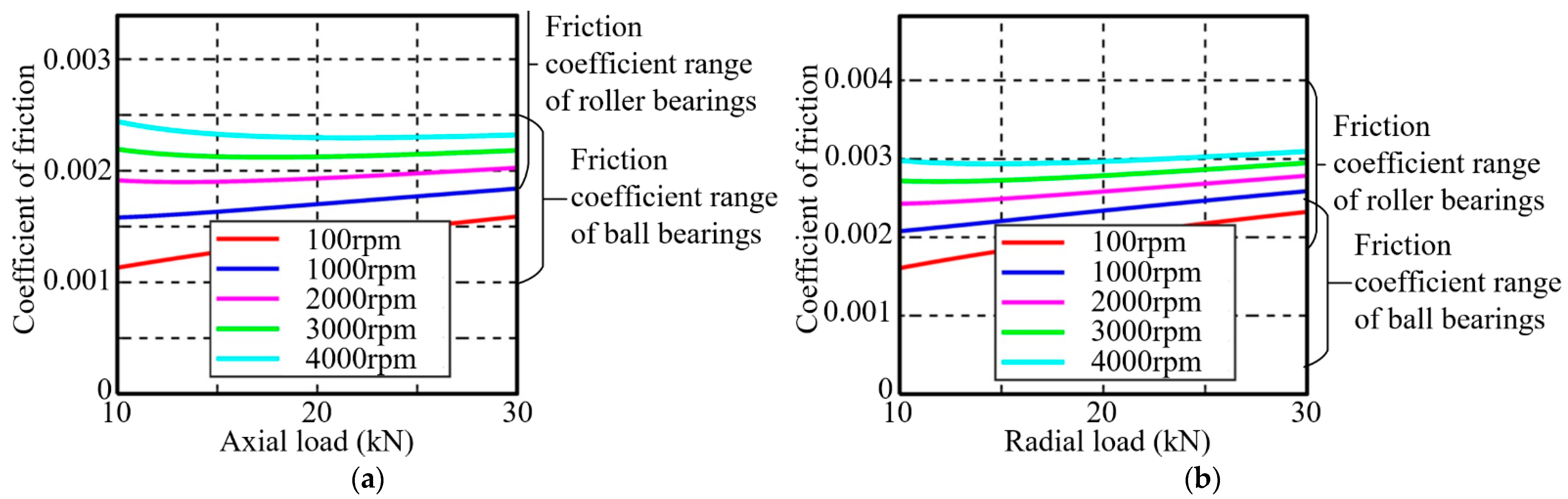
In the machinery field, bearing models are often selected according to the fatigue life of the bearing. When a constant load of 40–100% of the basic dynamic load rating is exerted on the bearing, the normal rotation turns of the bearing range from 15.6 million to 1.0 million, which can meet the requirements of the equipment on the fatigue life of the bearing. Therefore, in this paper, the friction coefficient of the PTRB prototype under an external load of 10–30 kN was analyzed. When the bearing speed was 100–4000 rpm, the variation of friction coefficient of the PTRB prototype with external load and bearing speed is shown in
Figure 4. The friction coefficient increased with the increase in bearing speed, wherein
μPTRBa ranged from 0.0011 to 0.0024, and
μPTRBr ranged from 0.0016 to 0.0031.
The performance indexes of the PTRB prototype and common high-quality bearing products were compared, as shown in
Table 3.
(1) Compared with ball bearings and roller bearings that had similar volume parameters and could carry axial load only, Ca of the PTRB prototype was superior to that of the single-direction thrust ball bearing and the double-direction thrust ball bearing but inferior to that of the unidirectional cylindrical roller thrust bearing. C0a of the PTRB prototype was inferior to that of the above three types of bearings. However, the above three types of bearings could not carry radial load and needed to be used in combination with other types of bearings, thus oversizing the overall bearing assembly. PTRB could carry axial–radial combined load or bidirectional axial load without being used cooperatively with other bearings.
(2) Compared with ball bearings and roller bearings that had similar volume parameters and could carry radial load only, both Cr and C0r of the PTRB prototype were superior to those of the deep-groove ball bearing and the cylindrical roller bearing, and the PTRB prototype was also able to carry axial load.
(3) Compared with ball bearings that had similar volume parameters and could carry axial–radial combined load, the basic static and dynamic load ratings of the PTRB prototype were superior to those of the single-row angular contact ball bearing and the double-row angular contact ball bearing.
(4) Compared with roller bearings that had similar volume parameters and could carry axial–radial combined load, the basic static and dynamic load ratings of the PTRB prototype were inferior to those of the single-row tapered roller bearing and the double-row tapered roller bearing. However, the single-row tapered roller bearing should be used in combination with other bearings, and the double-row tapered roller bearing had a large axial dimension.
Among the common high-quality bearing products in
Table 3, the friction coefficient of ball bearings ranged from 0.0010 to 0.0025, and the friction coefficient of roller bearings ranged from 0.0018 to 0.0040. The friction coefficient range of the PTRB prototype under axial load was 0.0011–0.0024, falling into the friction coefficient range of ball bearings. The friction coefficient range of the PTRB prototype under radial load was 0.0016–0.0031, falling into the friction coefficient range of ball and roller bearings.
According to the above analysis, the PTRB prototype had certain advantages over the common high-quality bearing products, such as small volume, high bearing capacity, no need to be used in pairs or combinations, and the ability to carry axial–radial combined load and bidirectional axial load. The PTRB with optimized structural parameters would be equipped with better performance and more outstanding advantages.
5. Effects of Structural Parameters on the Performance Indexes of PTRB
The effects of different structural parameters on the performance of the PTRB prototype were simulated and analyzed based on the theoretical models of load rating and friction torque. Conditions provided for the simulation and analysis are as follows: the dimension was unchanged, the axial load or radial load was 20 kN, the bearing speed was 4000 rpm, and the shear strength safety coefficient of the thread tooth roots was 2.
The value range of each structural parameter was set as follows:
(1) Since PTRB can carry both axial load and radial load, the value range of the contact angle was set to 30–60° by referring to the angular contact ball bearing.
(2) With the dimension of PTRB being constant, the number of thread teeth per roller was inversely proportional to the distance between adjacent threads. Therefore, a large number of thread teeth would narrow the distance between adjacent threads, resulting in high manufacturing costs and the risk of sliding wire in the bearing process; and a small number of thread teeth would reduce the load rating of PTRB. In light of the above, the value range of the number of thread teeth per roller was set to 8–16, and the corresponding distance between adjacent threads was set to 1.6–0.8 mm.
(3) To ensure that the contacting dimension of the contact ellipse meets the Hertz theory, the contact radius of the threaded roller should be larger than dR/2cosα, and the maximum value should be one order of magnitude less than the contact radius of the inner and outer rings. For ease of analysis, the value range of the contact radius of the threaded roller was set to 4.5–7.5 mm.
(4) With the dimension of PTRB being constant, the pitch diameter of the threaded roller was associated with that of the inner ring and outer ring. The larger the pitch diameter of the threaded roller was, the smaller the pitch diameter of the inner ring and outer ring was. Considering the pitch diameter of the threaded roller should be no larger than 2Rrrcosα required by the Hertz theory and the strength requirement, the value range of the pitch diameter of the threaded roller was set to 4.8–7.2 mm.
(5) The maximum number of threaded rollers was determined by the installation method of PTRB [
23], and the minimum value was 3. Given that a small number of threaded rollers might weaken the operating stability and bearing capacity of PTRB, the value range of the number of threaded rollers was set to 7–11.
The parameter improvement of PTRB can be classified into three types: load rating increases while friction torque keeps unchanged or slightly increases; friction torque decreases while load rating keeps unchanged or slightly decreases; load rating increases while friction torque decreases.
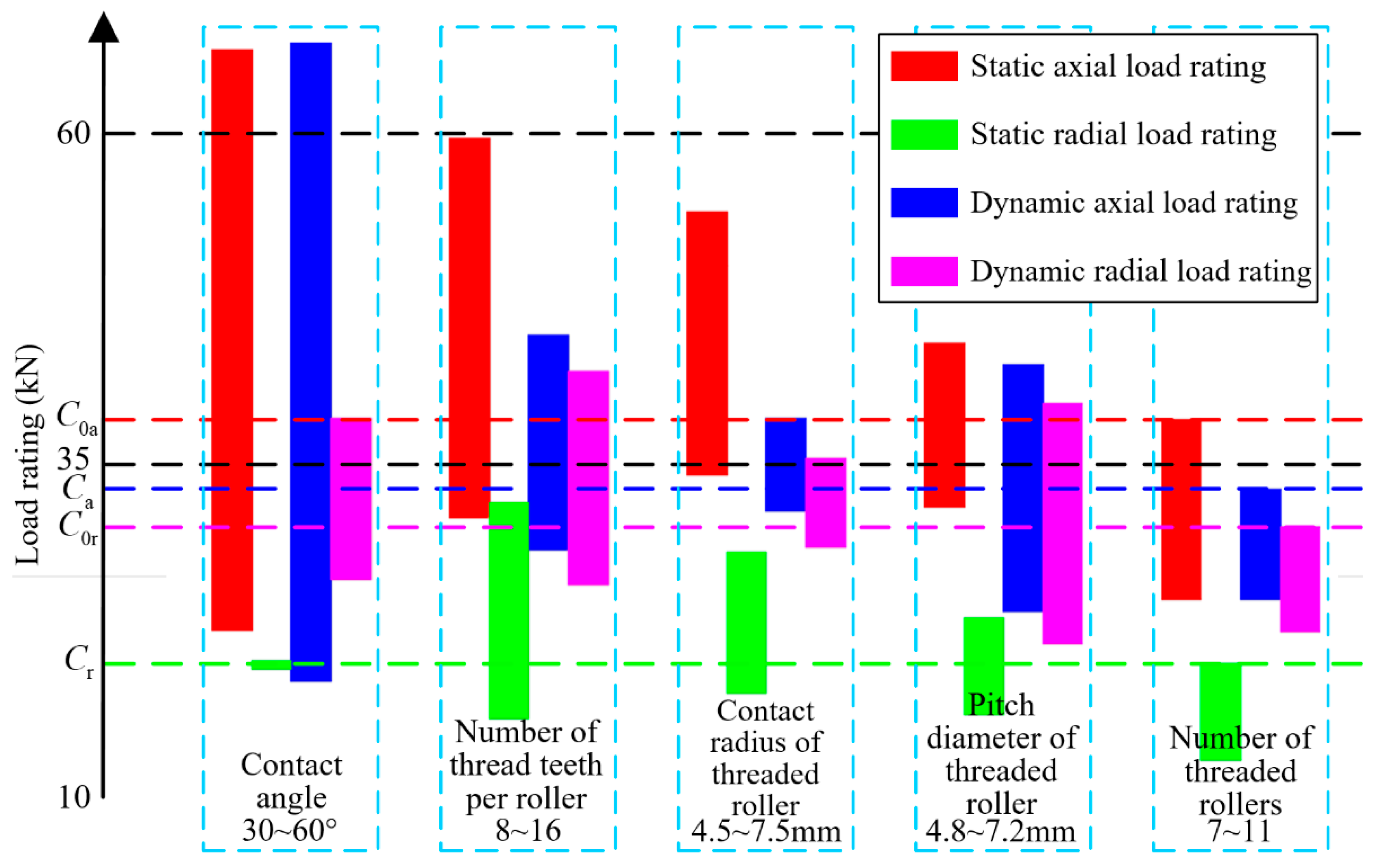
Through simulation analysis, the performance indexes of PTRB monotonically increased or decreased with the increase in the structural parameter values. Due to space limitations, the effect of structural parameters on performance indexes was expressed in figures and tables in this paper. The effect of different structural parameters on load rating is shown in
Figure 5 and
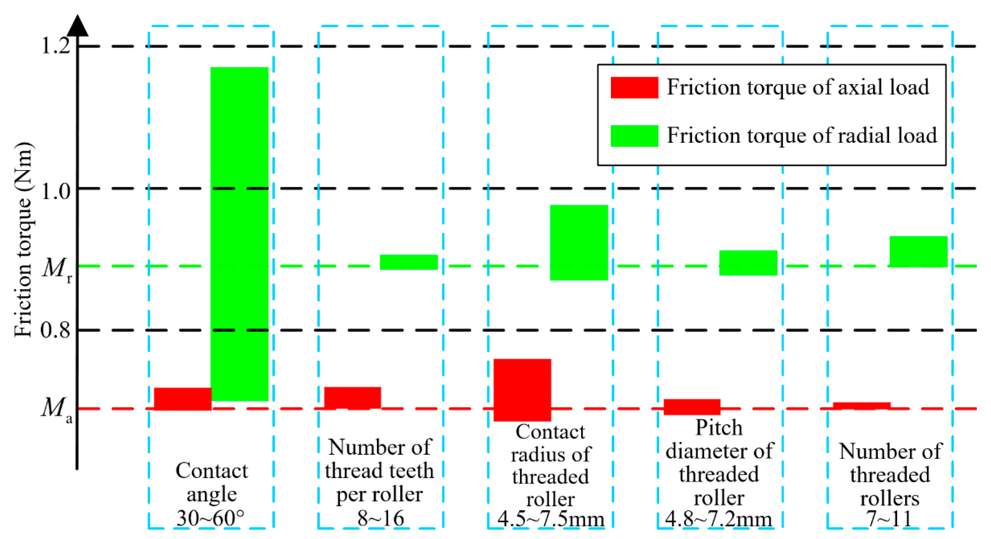
Table 4, and the effect of different structural parameters on friction torque is shown in
Figure 6 and
Table 5.
It could be seen from the analysis of figures and tables that:
(1) With the increase in the structural parameter values, the static and dynamic load ratings increased, leaving space for improvement, wherein the variation of the contact angle had the most significant effect on C0a and Ca, the variation of the number of thread teeth per roller had the most significant effect on C0r, and the variation of the pitch diameter of the threaded roller had the most significant effect on Cr.
(2) The friction torque increased with the increase in the structural parameter values, with exceptions that MPTRBa decreased with the increase in the number of threaded rollers and MPTRBr decreased with the increase in the number of threaded rollers or the number of thread teeth per roller. The variation of the contact angle had the most significant effect on MPTRBr, and the effect of other structural parameters on friction torque was less than 0.1 Nm.
(3) With the increase in the number of threaded rollers, the friction torque decreased, and the static and dynamic load ratings increased. Assuming that the mass was neglected, the maximum number of threaded rollers should be taken to obtain the optimum comprehensive performance.
(4) With the increase in four parameters, i.e., contact angle, number of thread teeth per roller, contact radius of the threaded roller, and pitch diameter of the threaded roller, the static load rating and the dynamic load rating increased, and so did the friction torque, causing conflict in the performance improvement of PTRB.
(5) Beyond the structural parameters given in
Table 4 and
Table 5, the variation of the pitch diameter of a threaded roller set had a minimal effect on load rating and friction torque, which could be neglected.
6. PTRB’s Parameter Optimization
Targeting the problem that there was a conflict between the variation of the structural parameters and the comprehensive performance improvement of PTRB, a multi-objective optimization design was conducted on PTRB under 20 kN and 4000 rpm in this section.
The maximum number of threaded rollers was always taken, and the contact angle, number of thread teeth per roller, contact radius of the threaded roller, and pitch diameter of the threaded roller were deemed as design variables:
The maximum load rating and the minimum friction torque were set as optimization objects:
The constraint conditions and value ranges were defined according to
Section 5, so the details are not described in this section.
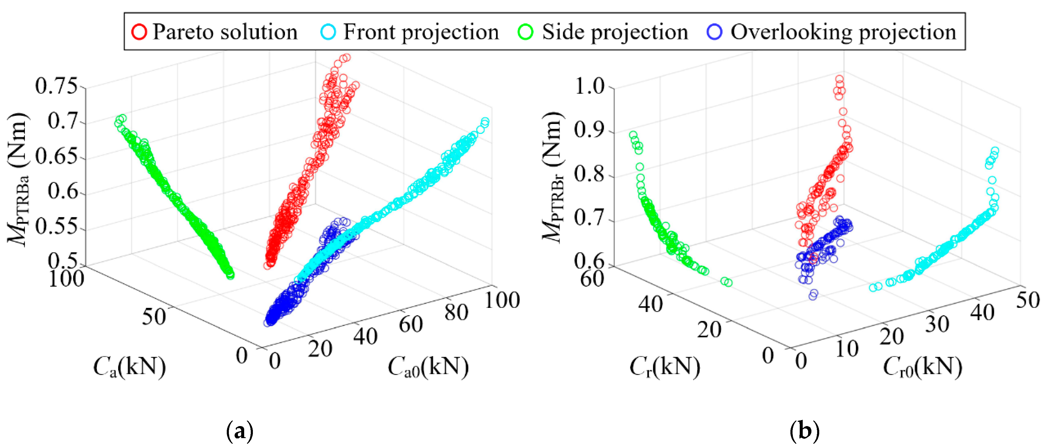
Through the multi-objective optimization design, the axial performance optimization result of PTRB is shown on the left side of
Figure 7, and the radial performance optimization result of PTRB is shown on the right side of
Figure 7. The friction torque increased with the increase in load rating. Two non-inferior solutions were selected from the two figures in
Figure 7, and the structural parameters and performance indexes are listed in
Table 6.
Comparative analysis suggests that taking the xa1 point where the load rating was large among the axial performance optimization results, though μPTRBa at xa1 was 4% larger than that of the PTRB prototype, its axial and radial load ratings were twice those of the PTRB prototype. Similarly, taking the xr1 point where the load rating was large among the radial performance optimization results, though μPTRBr at xr1 was 3% larger than that of the PTRB prototype, its axial and radial load ratings were also twice those of the PTRB prototype. Such performance optimization result was suitable for the equipment having a high requirement for the bearing capacity. At the points xa2 and xr2, where the friction torque and friction coefficient were small, though the load rating was slightly increased compared with the PTRB prototype, μPTRBa and μPTRBr were lowered by 9% and 13%, respectively. Such performance optimization result was suitable for the equipment having a high requirement for the friction coefficient of the bearing.
Therefore, the designers could, in consideration of their specific needs and optimized design results, select the structural parameters of PTRB in a targeted manner to enhance the design efficiency.
7. PTRB’s Performance Test
7.1. Research and Development of a Dedicated Performance Test System
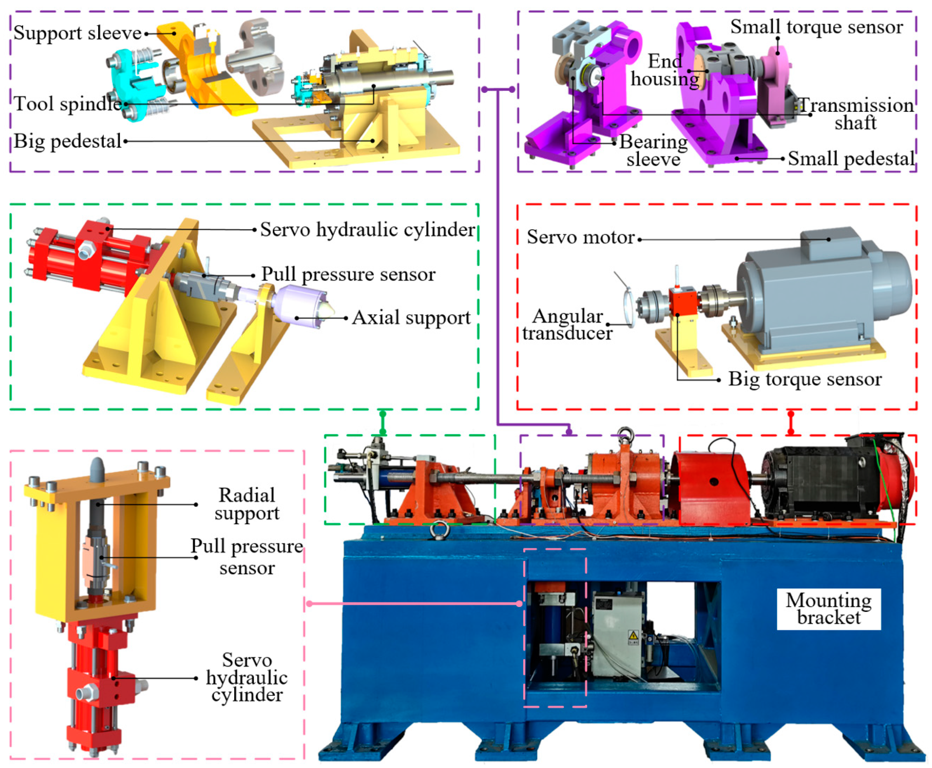
A dedicated performance test system was researched and developed according to the theoretical calculating data and relevant research for testing the performance of the PTRB prototype. The system could provide, either in an axial or radial direction of PTRB, a constant force of no less than 50 kN, an impact force of no less than 35 kN, a rotating speed of 4000 rpm, and a sweep-frequency motion with a rotating angle of ±30° and a frequency of 2 Hz. As shown in
Figure 8, the mechanical part of the performance test system includes a motor, load components, friction torque, a radial life test assembly, an axial life test assembly, a mounting bracket, and a heating/cooling assembly, wherein the heating/cooling assembly was an externally connected independent air heater/cooler, which was used to heat or cool the PTRB by outputting hot or cool air to maintain the temperature of PTRB at 20 °C–60 °C. The material object is not shown in the figure.
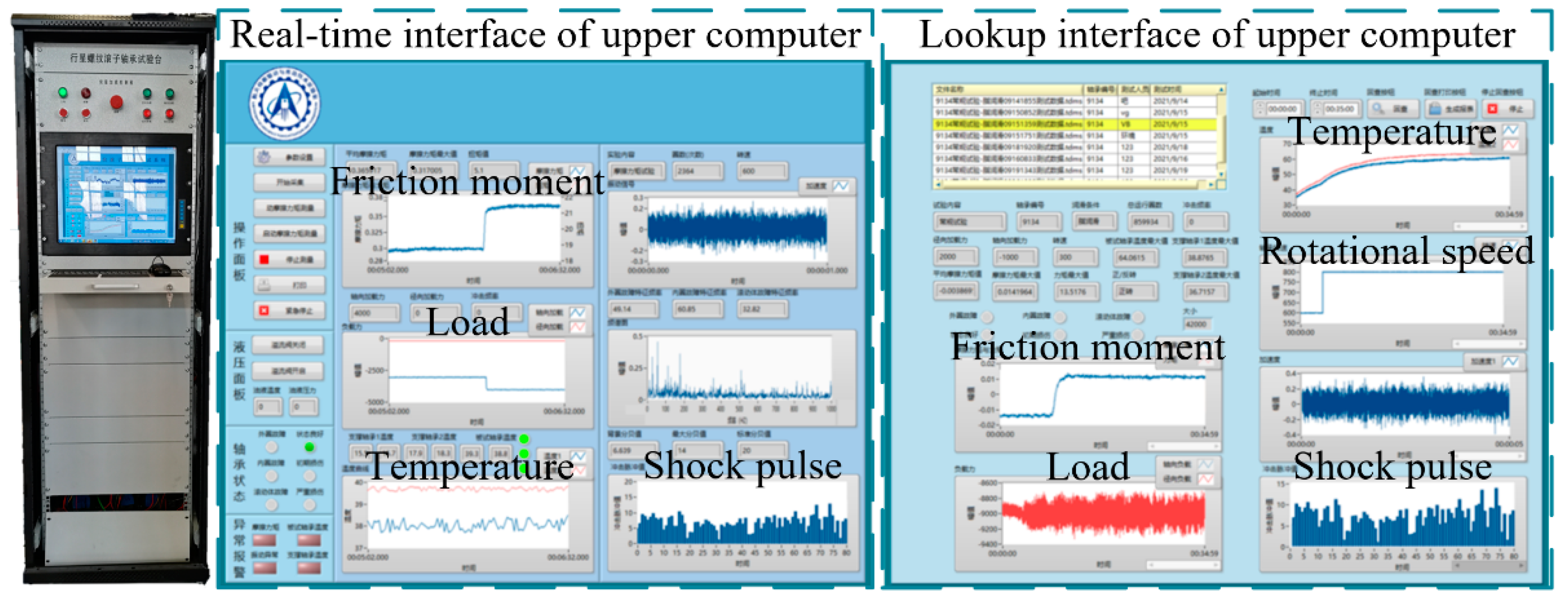
The test and control part of the performance test system includes motion control, signal acquisition, and data processing. Since the motion complexity of the servo motor and the servo-hydraulic cylinder were not highly demanded in the test, the closed-loop control method is not described in detail hereunder. As for signal acquisition and data processing, firstly, the data acquisition and control system was used to acquire the temperature, tension and pressure, torque, rotating speed, and acceleration signal, followed by the data reading, processing, and storage of the upper computer. Finally, the results were displayed in the upper computer interface programmed by LabVIEW in tables, average values, and curves.
The control system and upper computer interface are shown in
Figure 9. The real-time interface of the upper computer is used to display the shock pulse value of PTRB in real time and monitor its health status. It also displays the PTRB friction torque, the load applied to PTRB, and the motor rotation speed in real time, as well as the outer ring temperature. If the PTRB temperature, system friction torque, or load data are abnormal, the buzzer alarm will be triggered. The lookup interface of the upper computer is used to check the test data and images of the temperature sensor, tension and pressure sensor, acceleration sensor, torque sensor, and angle sensor in any time period.
7.2. Performance Test and Analysis of the PTRB Prototype
7.2.1. Preparations
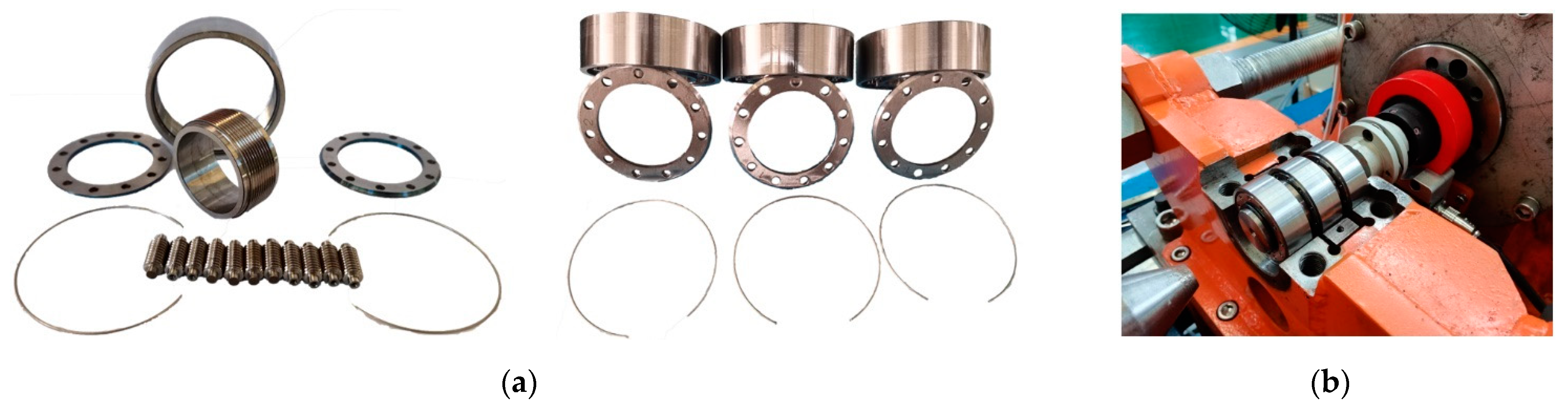
Before the test, all components of PTRB were cleaned and dried with kerosene to ensure the cleanness of PTRB and the frock clamp, as shown in
Figure 10. After the assembly of PTRB, the inner and outer rings were rotated manually. If the rotation was smooth without being stuck, the bearing could be defined as a test object, and then a small amount of grease was evenly added, or oil was dropped for lubrication during the test; otherwise, the bearing could not be tested. Then, the inner ring of PTRB was installed on the transmission shaft, and the outer ring of PTRB was installed in the frock clamp, both in an interference fit manner. Running-in was conducted on PTRB under 2 kN, 500 rpm, and 10,000 r. Relatively stable and accurate test data should be guaranteed during the test process.
7.2.2. Friction Torque Test
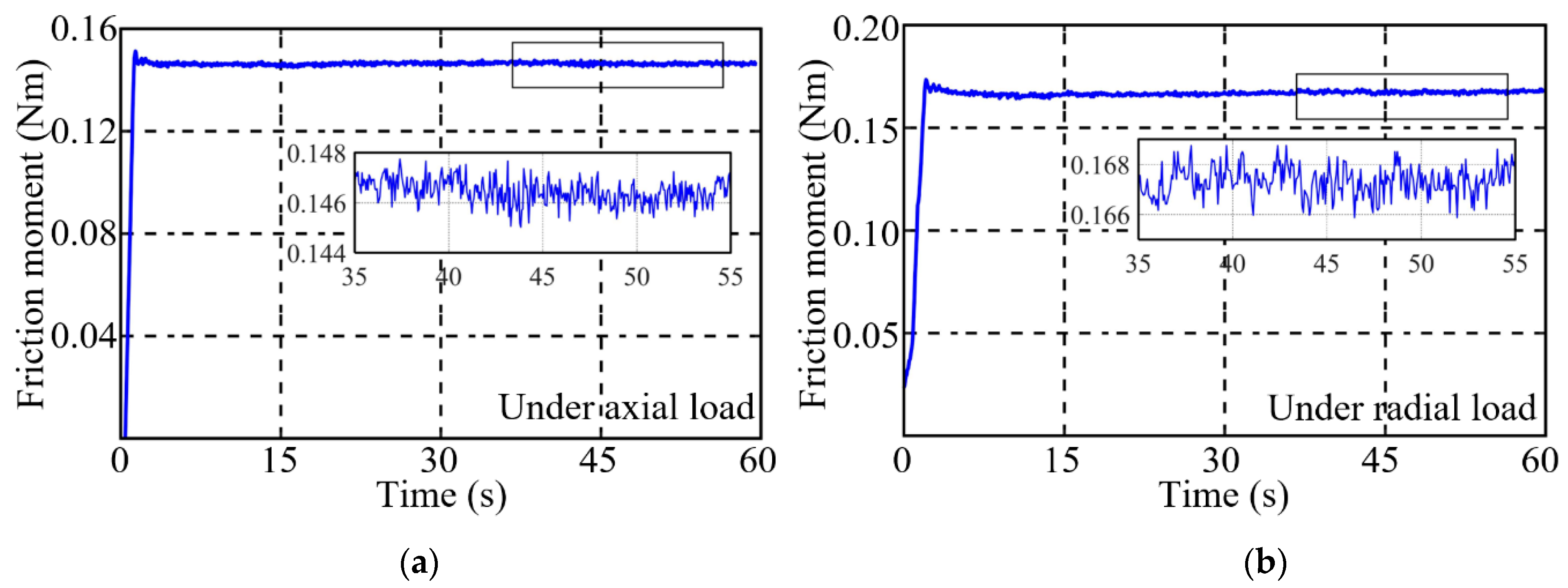
The temperature of PTRB was maintained at 40 °C using the heating/cooling assembly. Based on this, a friction torque test was carried out on the PTRB prototype under an external load of 5 kN, a bearing speed of 800 rpm, and a single test duration of 60 s. The
MPTRBa and
MPTRBr curves obtained are shown in
Figure 11, respectively. By averaging the test values in a stable segment after repeated measurements, the
MPTRBa and
MPTRBr of the PTRB prototype obtained in this state were 0.146 Nm and 0.167 Nm, respectively.
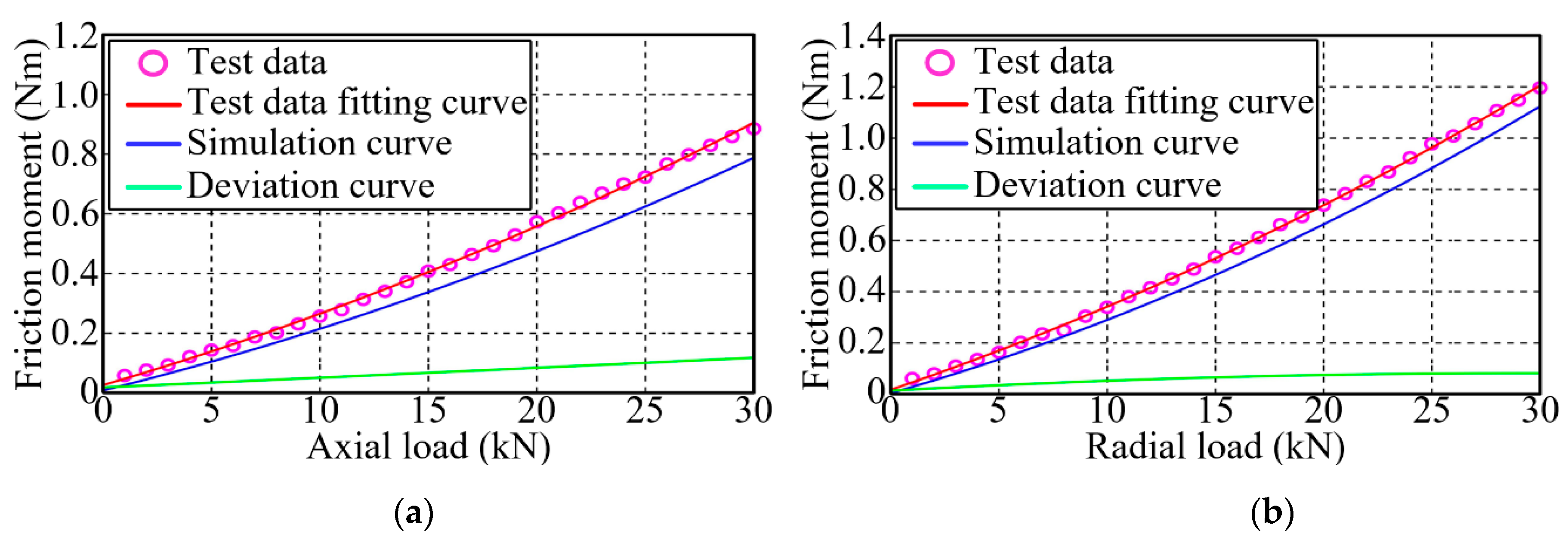
To analyze the effect of the variation of external load on the friction torque of PTRB, a friction torque test was carried out on the PTRB prototype under an external load of 1–30 kN and a bearing speed of 600 rpm. The value of the friction torque in a stable segment was averaged after repeated measurements, and the simulation and test data are listed in
Table 7. The test data were fitted and compared with the theoretical simulation results, as shown in
Figure 12. Under the same bearing speed, the variation trend of the test data and the simulation data with the external load was consistent, and an approximately linear increase was seen in friction torque with the increase in external load. Under any external load, the test data were slightly greater than the simulation data, with a deviation of no more than 0.1 Nm. Under an external load of 20 kN and a bearing speed of 600 rpm,
μPTRBa and
μPTRBr were 0.0019 and 0.0025, both falling into the range of theoretical calculation.
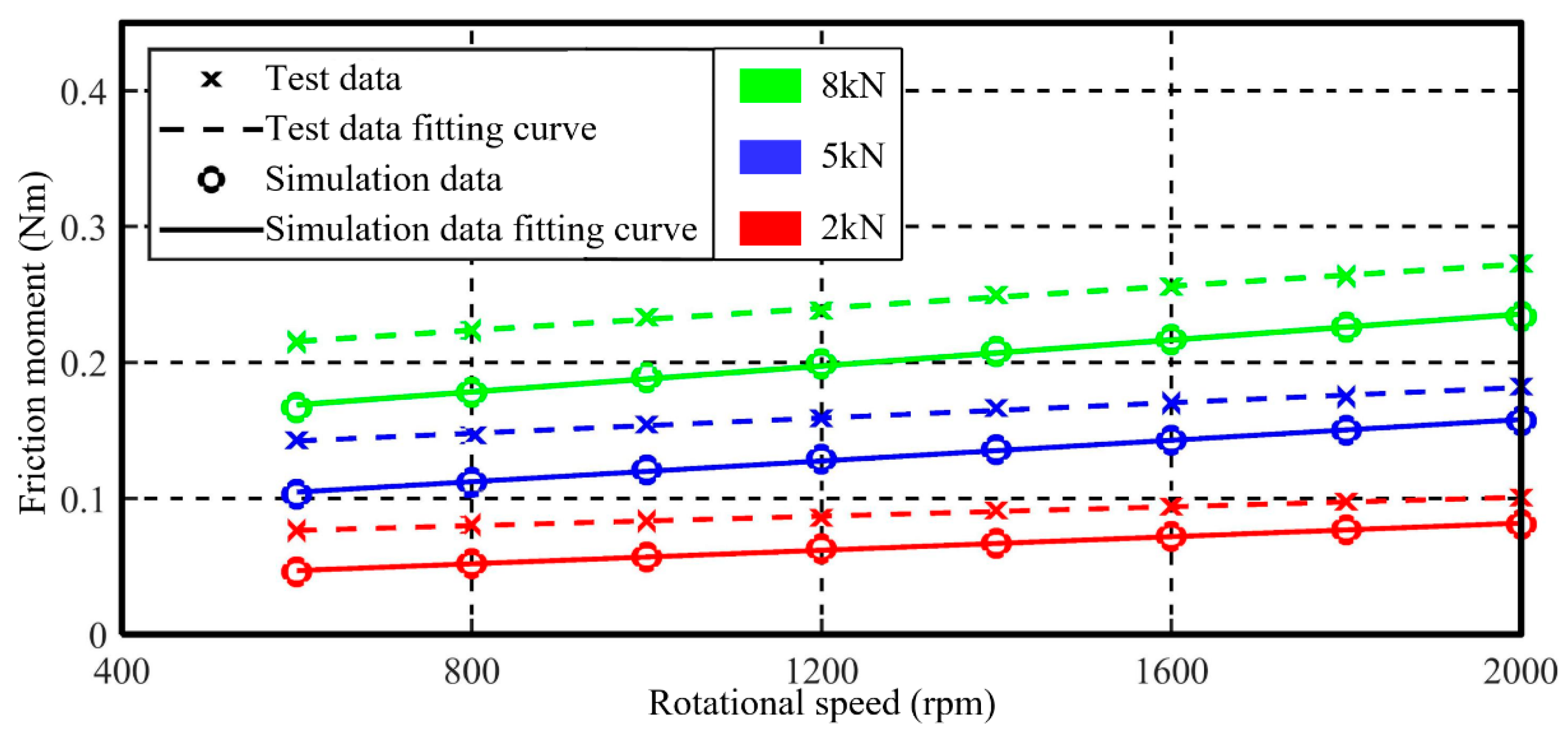
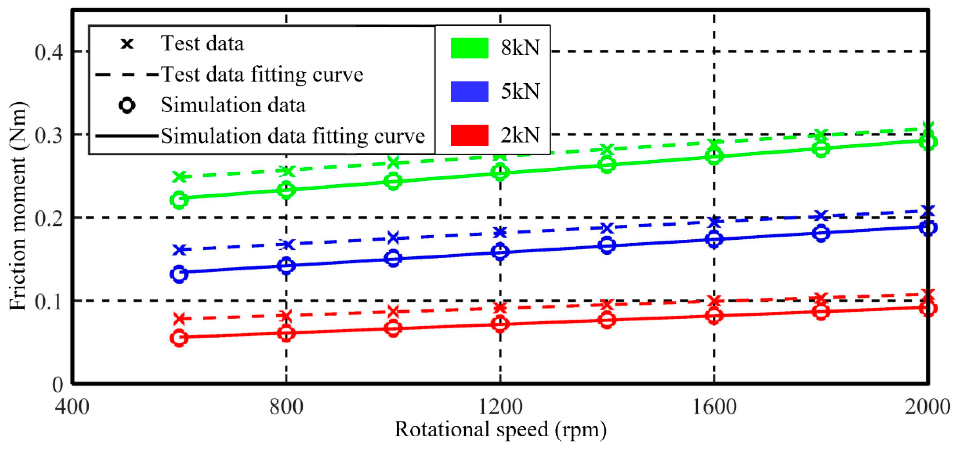
To analyze the effect of the variation of bearing speed on the friction torque of PTRB, a friction torque test was carried out on the PTRB prototype under an external load of 2 kN/5 kN/8 kN and a bearing speed of 600 rpm–2000 rpm. The simulation data and the test data are listed in
Table 8. A comparison was conducted between the test data and the simulation data, as shown in
Figure 13 and
Figure 14. Under the same external load, the variation trend of the test data and the simulation data with the bearing speed was consistent, and an approximately linear increase was seen in friction torque with the increase in bearing speed. Under any bearing speed and external load, the test data were slightly greater than the simulation data, with a deviation of no more than 0.05 Nm.
7.2.3. Static Bearing Capacity Test
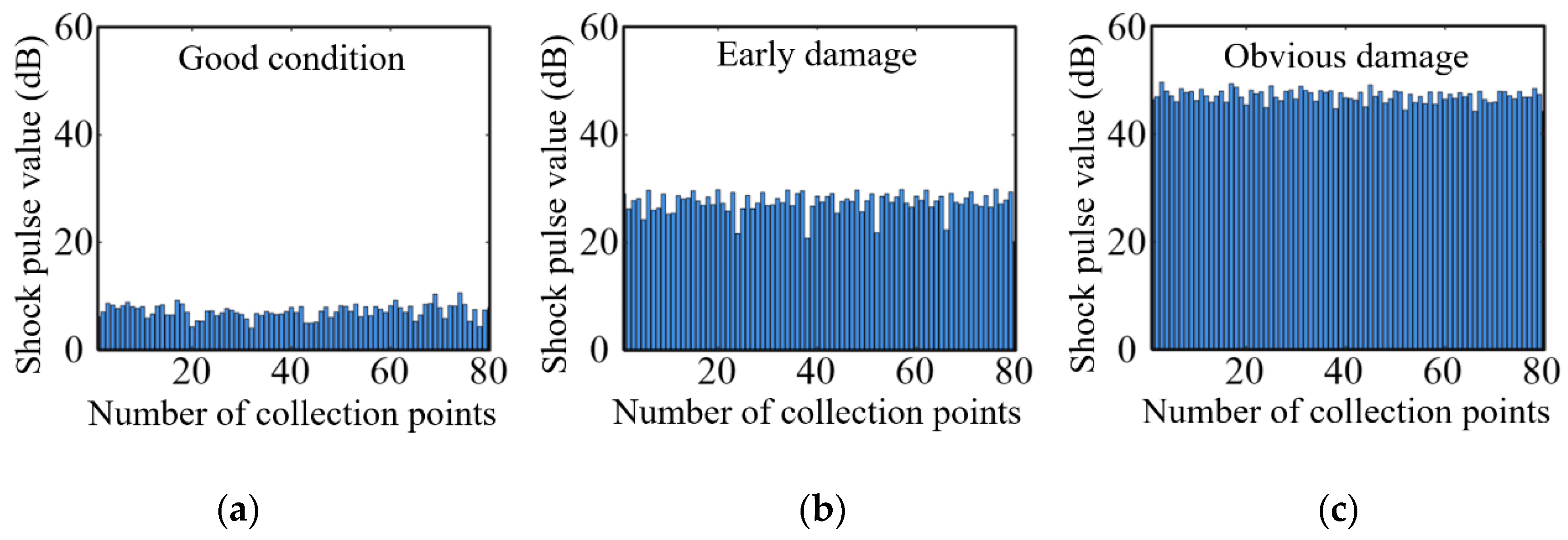
The shock pulse method is a common way to judge the health status of roller bearings. As shown in
Figure 15, when the shock pulse ranged from 0 to 20 dB, it indicates that the bearing was running in a healthy state; when the shock pulse ranged from 20 to 35 dB, it indicates that the bearing suffered from early damage; when the shock pulse ranged from 35 to 60 dB, it indicates that the bearing was obviously damaged [
37,
38,
39].
The shock pulse method was used to judge the health status of the PTRB prototype in this paper. With the bearing speed maintained at 0, a static bearing capacity test was carried out on the PTRB prototype under a single test duration of 3 h and an axial load of 38 kN or a radial load of 20 kN. After a single test, a friction torque test was conducted on the PTRB prototype under an external load of 5 kN and a bearing speed of 800 rpm. Meanwhile, the shock pulse value of the bearing was monitored.
After multiple tests, the friction torque and the shock pulse value of the PTRB prototype had no significant changes, meeting the requirements of the relevant standards on the basic static load rating. That is, the basic static axial load rating of the PTRB prototype was no less than 38 kN, and the basic static radial load rating was no less than 20 kN.
7.2.4. Impact Life Test
It is known that the ball bearing of the same size as the PTRB prototype cannot satisfy the requirements of the large mountain walking machine platform on impact life. For testing the impact resistance of the PTRB prototype, an impact life test was conducted on the PTRB prototype under an impact load of 20 kN, a rotating angle of ±30°, a frequency of 2 Hz, and 100,000 impact times. Before and after the impact life test, friction torque tests were conducted on the PTRB prototype under an external load of 10 kN and a bearing speed of 600 rpm. Meanwhile, the shock pulse value of the bearing was monitored.
Multiple measurement results show that before the impact life test, MPTRBa and MPTRBr were 0.257 Nm and 0.339 Nm, and the shock pulse value was approximately 10 dB. After the impact life test, a slight increase was seen in the dynamic friction torque compared with that before the test, MPTRBa and MPTRBr were 0.329 Nm and 0.416 Nm, and the shock pulse value was approximately 27 dB. It indicates that the bearing suffered from early damage rather than complete damage. Hence, the PTRB prototype exhibited an impact resistance superior to the common high-quality bearing products and could preliminarily meet the requirements of the large mountain walking machine platform.
To sum up, within the range of dynamic load rating, the test data were slightly larger than the simulation data for friction torque, with a deviation of no more than 0.1 Nm, manifesting a relatively high degree of precision of the theoretical model. The deviation might be attributed to machining error and nonlinear friction torque. When the bearing was required to carry a dynamic load of 20 kN-30 kN, the system would obtain great driving force, and the deviation of 0.1 Nm would have a minimal effect on the system efficiency. When the PTRB prototype was used as an electro-mechanical actuator in combination with a planetary roller screw pair of the same power level, the efficiency was nearly 97%, and the deviation was no more than 0.5%. Though the PTRB prototype had a slightly larger friction torque than the ball bearing, it exhibited better static bearing capacity and impact resistance life. In light of the good comprehensive performance of the PTRB prototype, the researchers could conduct a targeted optimization design according to their specific needs to obtain better comprehensive performance.
8. Conclusions
In this paper, an all-around study was carried out on PTRB with a unique structure and strong bearing capacity. The main efforts and important conclusions can be summarized as follows:
Based on the contact characteristics and the theoretical model of load distribution, the theoretical models of load rating and friction torque for PTRB under axial load or radial load were derived, respectively, according to the relevant standards. Then, an analysis was conducted on the performance of the PTRB prototype, with C0a, Ca, C0r, and Cr being 38.36 kN, 33.20 kN, 19.93 kN, and 30.26 kN. Under an external load of 0 kN–30 kN and a bearing speed of 100 rpm–4000 rpm, μPTRBa and μPTRBr ranged from 0.0011 to 0.0023 and 0.0016 to 0.0031, respectively. The PTRB prototype had certain advantages over the common high-quality bearing products, such as small volume, high bearing capacity, no need to be used in pairs or combinations, and the ability to carry axial–radial combined load and bidirectional axial load.
The effects of different structural parameters on the performance of PTRB were simulated and analyzed with the dimension being constant. Within the value range of the structural parameters, the basic load rating and the friction torque of PTRB monotonically increased or decreased with the increase in the structural parameter values, and there was a certain space for improvement for the basic load rating. The maximum number of threaded rollers was taken to obtain the optimum comprehensive performance, and the effect of the variation of the pitch diameter of a threaded roller set on PTRB performance could be neglected. There was a conflict between the variation of four parameters and the performance improvement of PTRB, i.e., contact angle, number of thread teeth per roller, contact radius of threaded roller, and pitch diameter of threaded roller.
A multi-objective optimization design was carried out on PTRB under axial load and radial load separately with basic load rating and friction torque as optimization objects to improve its comprehensive performance further. When the bearing capacity of PTRB was highly demanded, the optimization results selected could improve the axial and radial load ratings to 200% of the PTRB prototype, and the increase in friction torque was no more than 4%. When the friction coefficient of PTRB was required to be small, the optimization results selected could reduce μPTRBa and μPTRBr by 9% and 13%, respectively, and also slightly increase the load rating. The multi-objective optimization and the selection of optimization results could effectively improve the design efficiency of PTRB.
A dedicated performance test system was built to verify C0a≮38 kN and C0r≮20 kN of the PTRB prototype. Moreover, the PTRB prototype could meet the requirement of the large mountain walking machine platform on the PTRB’s impact life of more than 100,000 times under an impact load of 20 kN. Within the range of load rating, the deviation between the test data and the simulation data for the friction torque was less than 0.1 Nm. When PTRB was used in combination with a planetary roller screw pair of the same power level, the efficiency was nearly 97%, and the deviation was no more than 0.5%. The performance of the PTRB prototype and the correctness of the theoretical model were verified through tests. In the follow-up work, further optimization should be carried out on PTRB according to the specific needs to raise the comprehensive performance of PTRB to a higher level.


