Article

Visual-Servoing Based Global Path Planning Using Interval Type-2 Fuzzy Logic Control

1
Faculty of Engineering, Inonu University, Malatya 44280, Turkey
2
Tijuana Institute of Technology, Tijuana 22414, Mexico
*
Author to whom correspondence should be addressed.
Axioms 2019, 8(2), 58; https://doi.org/10.3390/axioms8020058
Submission received: 1 March 2019 / Revised: 19 April 2019 / Accepted: 1 May 2019 / Published: 10 May 2019
(This article belongs to the Special Issue Type-2 Fuzzy Logic: Theory, Algorithms and Applications)

Abstract

:
Mobile robot motion planning in an unstructured, static, and dynamic environment is faced with a large amount of uncertainties. In an uncertain working area, a method should be selected to address the existing uncertainties in order to plan a collision-free path between the desired two points. In this paper, we propose a mobile robot path planning method in the visualize plane using an overhead camera based on interval type-2 fuzzy logic (IT2FIS). We deal with a visual-servoing based technique for obstacle-free path planning. It is necessary to determine the location of a mobile robot in an environment surrounding the robot. To reach the target and for avoiding obstacles efficiently under different shapes of obstacle in an environment, an IT2FIS is designed to generate a path. A simulation of the path planning technique compared with other methods is performed. We tested the algorithm within various scenarios. Experiment results showed the efficiency of the generated path using an overhead camera for a mobile robot.

1. Introduction

Over the last two decades, the use of mobile robots has increased in many areas, from industrial work to research and home use. Computer vision has become a major research topic in robot control. Autonomous mobile robots use vision systems to perform a given mission. Path planning is critically important for a mobile robot to be able to carry out its assigned task. Essentially, path planning algorithms determine how the robot should orient itself with accuracy, safety, and efficiency. Path planning and path following are two important problems which need to be solved in order for the mobile robot to perform a task. To solve these problems, one needs to find answers to the following questions: Where am I? Where am I going? How do I get there? What is the best way to get there? These are complex issues in the robotic field if they occur in dynamic and unknown environments. To answer these fundamental questions one needs to know their philosophy and use them together [1]. There are various issues and uncertainties which need to be considered for an efficient, robust, and safe path. Type-2 FIS is a well-established powerful hybrid technology that can be implemented within the visual system. Interval type-2 [2,3,4,5,6,7,8,9,10,11,12] FIS was chosen to overcome these uncertainties and develop robust, flexible control, mainly due to its efficiency in avoiding local obstacles. Path planning control inputs parameters including robot position information, target position, and description of environment [13]. Visual servoing is an important concept which can be useful in providing the capability to employ visual information to control the mobile robot motion control in this field. Here we are interested in the overhead camera, which can provide information to generate the mobile robot path. The overhead cameras can be used to sense the position of the robot and coordinate their motions toward their destination without collision obstacles. Two important factors are relevant to solving the path planning problem. The first is environment type (static or dynamic), and the second is the path planning algorithm (global off-line or local on-line). In these experiments, global path planning has been emphasized in a static environment. Global path planning algorithms are executed in static environments.
In this paper, we propose an effective visual-servoing based global path planning technique using interval Type-2 FIS and comparison with various path planning algorithms. Our contributions are as follows:
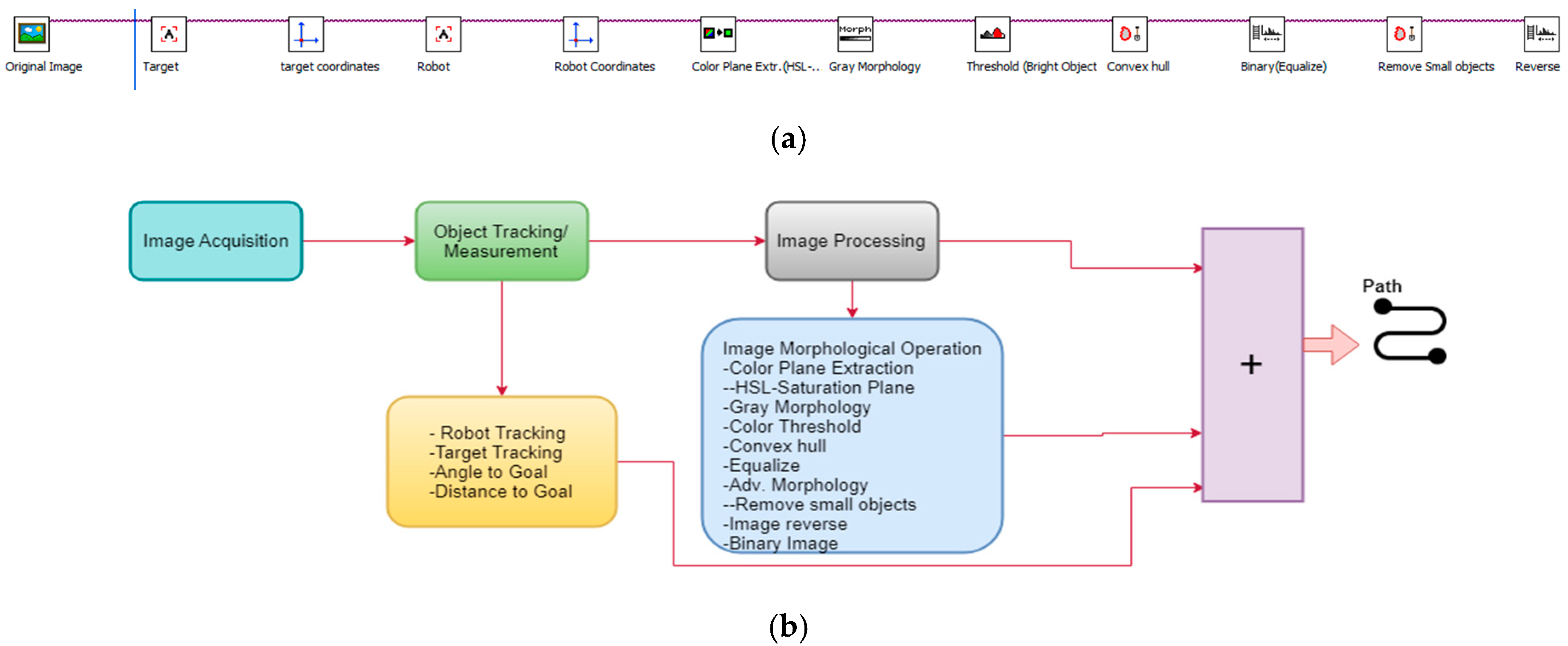
  • A robust vision-based obstacle-free path planning algorithm has been developed and implemented to enable safer global navigation.
  • A new framework for the evolutionary algorithm is given.
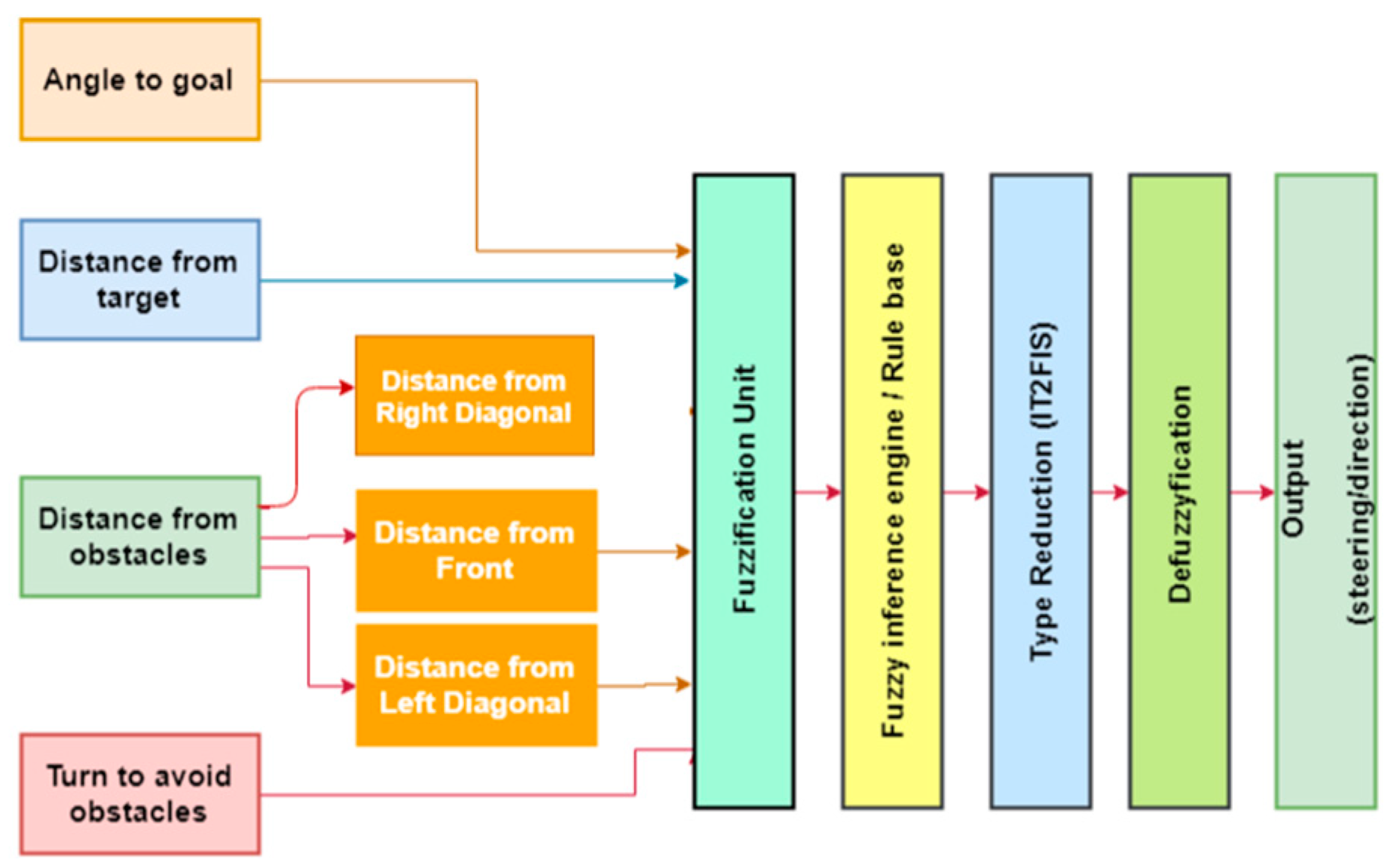
  • A fuzzy inference system has been proposed and integrated into the proposed intelligent navigation framework to adjust the wheel velocity.
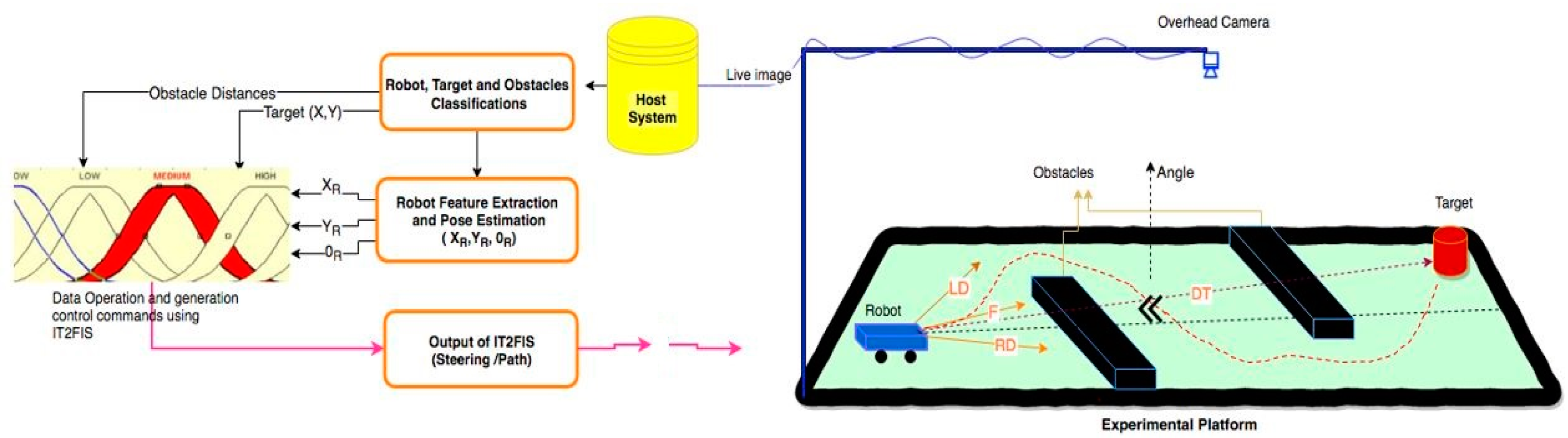
  • A novel distance estimation method using overhead camera systems is given which employs scale parameters from the IT2FIS algorithm.
  • Finally, we combine the advantages of the traditional path planning algorithm with the proposed technique to improve computational efficiency.
In real-world experiments in particular, there are significant changes due to environmental factors like constant illumination and lighting condition factors. These changes are factors that can be encountered when creating an effective planning algorithm. However, a key aim should be to increase the proposed architecture as mentioned previously to reach an acceptable level of performance under real conditions. This study aims to minimize both systematic and non-systematic errors and to develop a high-performance path planning algorithm.

2. Literature Review

Navigation and obstacle avoidance are one of the fundamental problems in mobile robotic systems. Many algorithms related to this subject have been developed [14]. Neuro-Fuzzy architecture [15,16,17,18,19], A* [20,21], D* [22] (the dynamic version of the A*), Genetic Algorithm [23,24], Dijksta’s Algorithm [25], BFS [26], and DFS [27] are the methods used for path planning which consider the cost efficiency. Another method for generating a path plan using potential field functions is the APF [28,29] method. Each method has the purpose of finding a reliable and cost-effective technique. RRT [30] is a path planning method which is widely used in robotic studies. It aims to achieve an unobstructed path between the start and destination positions in an unknown environment. A more advanced version of RRT is the bidirectional-RRT (bi-RRT) [31] path planning algorithm. This algorithm is completed using two trees that start to separate from both the starting and the target positions. Visual-servoing (VS) methods have been widely used in various path planning applications [32,33,34,35,36,37] and use an image sensor in a feedback loop for trajectory control. Global path planning provides a global map in which the robot initial position, goal point, and obstacle positions are determined. A fixed overhead camera is used to generate a 2D image model of the environment and the proposed method is advanced to plan the robot path. For this purpose, vision-based path planning has been integrated with IT2FIS in this way and robust and reliable methods for avoiding obstacles have been developed [4,38,39]. The proposed algorithm is assured of a reliable and feasible path that is visible to the camera. Traditional sensing techniques such as infrared detectors, laser scanners, and ultrasonic sensors are used to detect obstacles [35]. Due to systematic and non-systematic errors, these sensors do not always give the correct result. Systematic errors can be caused by the physical structure of the robot hardware parts, including the encoder and sensor, but non-systematic errors are usually caused by sliding, pounding, or falling. Measurement resolutions can be affected by external situations such as light conditions, detection range, and expensive and often bulky systems. On the other hand, vision sensors are a low-cost motion control and are effective in decreasing errors as mentioned; they are also useful robotic sensors. The vision system provides necessary information about obstacles, as well as, simultaneously, the position and orientation of the mobile robot in the initial and goal position. Parameter ranges and system uncertainties in the position control environments are required to deal with the controller [40]. Soft computing methods like fuzzy logic [41,42,43,44,45,46] are one of these controllers. These controllers have powerful advantages such as being low cost, being easy to control and being designable without knowing the exact mathematical model of the process. Because of their simple design, which decreases the mathematical model’s complexity, fuzzy logic can be used in decentralized form, which is preferable to a mobile robot over centralized control. In mobile robot applications and path planning, many uncertainties may be encountered. These are uncertainties of inputs, uncertainties of control action, and linguistic uncertainties. These all become uncertainties about fuzzy logic membership functions [4]. Uncertainties associated with changing unstructured environments cause problems in the determination of membership functions. An IT2FIS technique is suitable for dealing with these uncertainties [47,48]. This ability is supported by the fact that the third type-2 fuzzy logic [49,50,51] sets dimensions, and its footprint of uncertainty is sufficient in comparison with what type-1 fuzzy logic [52] sets in modeling on uncertainty. IT2FIS is suitable for real world applications regarding the control of mobile robots [53,54].

3. Concepts of the Proposed Method

To cope with uncertainties, we used advances recently made on type-2 FIS to enable the development of an intelligence vision system based on IT2FIS for global path generation. In this paper we focused on VS-based mobile robot global path planning using an overhead camera. The particular concept of the proposed methods is to use virtual inputs that are completely generated from image information. The extracted visual information from interested objects which are visible to the camera enables the generation of the desired path. The overall technique of the proposed algorithm is demonstrated in Figure 1.
The IT2FIS algorithm is used as an effective intelligence technique that deals with parameter variation and system uncertainties. It also offers a simple and cost-effective design advantage without the complexity of its mathematical model. The main contribution of this experimental study is its combining VS and IT2FIS to generate a mobile robot path in static and unstructured environments. The proposed methods have been tested in various cases to validate the system. The simulation results show the validity of the proposed techniques.
This paper is organized as follows. In Section 2, the problem definition is explained. Section 3 describes the structure and functionality of the vision algorithm. Section 4 handles the type-2 fuzzy inference system. The experimental and simulation results and system implementation are presented in Section 5. Finally, concluding remarks are given in Section 6.

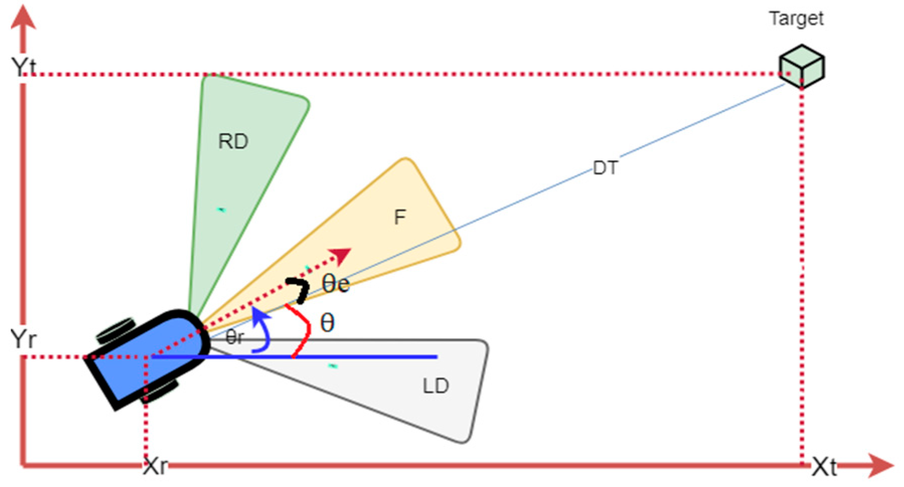
4. Problem Definition

Path planning, localization, and motion control are common problems in mobile robot control. To overcome such problems, a visual-servoing-based technique that extracts visual information from a fixed overhead camera in order to use IT2FIS to generate global path planning is proposed. In order to reach the desired goal configuration, image processing morphological operation has been used to detect the mobile robot initial position pose, orientation, target coordinates, and obstacle positions via an overhead camera (see Figure 1). In the VS control loop, the vision sensors can always track the obstacles surrounding the robot using left diagonal (LD), front (F), and right diagonal (RD) obstacle detection sensors. These are virtual sensors which are tracked by the image processing system. These sensors and the robot position and orientation information, denoted by (XR, YR, θR), have been served as the inputs to the IT2FIS controller to enable the generation of the desired obstacle-free path. The relationship between the generated path in 2D image space and its identical path in the real robot work field defines visual servoing.

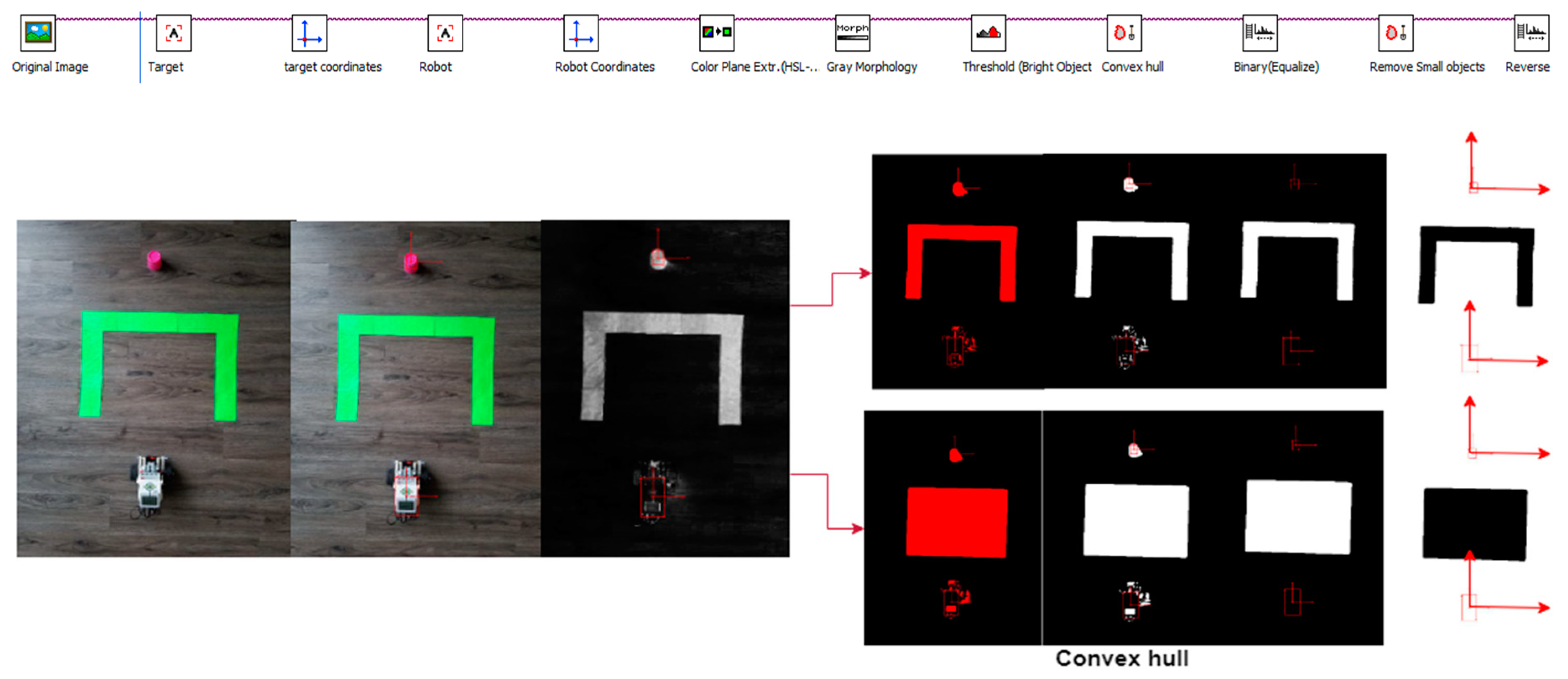
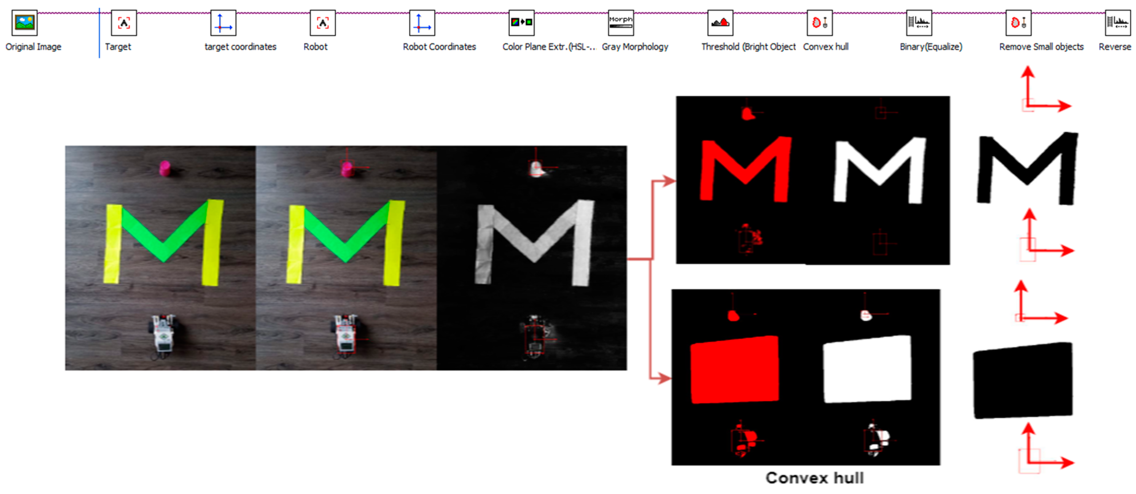
5. Visual Servoing Algorithm

In this section the overall procedure (see Figure 2) of the algorithm that we have developed for solving the problem of robotic path planning is described. The algorithm starts by capturing the experimental environment’s image from the overhead camera. In order to generate the robot motion environment, the robot world, or the robot map (robot, obstacles, and target position), a number of morphological processes are performed. Robot path planning algorithms use a map to obtain information about the obstacles and accessible paths. To generate the shortest path, robot initial position, target position, and distance map information are required as inputs.
The process of the visual tracking algorithm is given in Figure 2. The aim was to generate an obstacle-free robot path by using an overhead camera. We have proposed an effective method for object tracking. The phases of application of sub-systems of morphological processes with object tracking and image processing with image processing are highlighted in Figure 2. The RGB image from the camera is converted to HSL color space-based thresholding. During experimental simulation, a number of morphological processes were applied to prevent friction and collision. The boundaries of the obstacles were dilated so more reliable path planning was achievable. The Convex-hull algorithm was used to prevent the robot from falling to the local minimum. The target and robot coordinates were determined in pixels using a shape adapted mean shift algorithm. This algorithm [40] uses asymmetric and anisotropic kernels for object tracking. The algorithms were implemented using NI Vision Builder programming tools. A shape-adapted mean shift algorithm was implemented which provided angular as well as a linear offset in object shapes. This algorithm allows for the tracking of object templates with changing shapes and size using a built-in function from NI Vision Assistant. The tracking template position is considered as the reference and its coordinates are regarded. In the final image analysis, the object’s coordinate system is obtained. There are a number of steps which need to be considered to generate the path. The formulation of the input parameters that are obtained from the visual system are explained and formulated by using Figure 3. The pose of the mobile robot (Xr, Yr, θr) in the global frame can be defined by the center of the mobile robot position. Here, the visual information (location and orientation) is extracted from the visual odometry. In order to eliminate the effects of slipping and mechanical shock, the control loop of visual servoing processes works with the current information.
Assuming that the mobile robot’s initial position information and target position are known, as shown in Figure 3, we calculate the position errors as
e x = X t X r = D T cos ( θ r )
e y = Y t Y r = D T sin ( θ r )
where DT corresponds to the current distance between the mobile robot ( X r , Y r ) and the target ( X t , Y t ), which is expressed as Equation (3):
D T = ( e x ) 2 + ( e y ) 2
The robot current angle ( θ r ) according to the target is computed in Equation (4):
θ r = t a n 1 e y e x
The error of angle is given in Equation (5):
θ e = θ r θ
The control objective is to design a fuzzy logic controller to generate the desired robot path configuration.

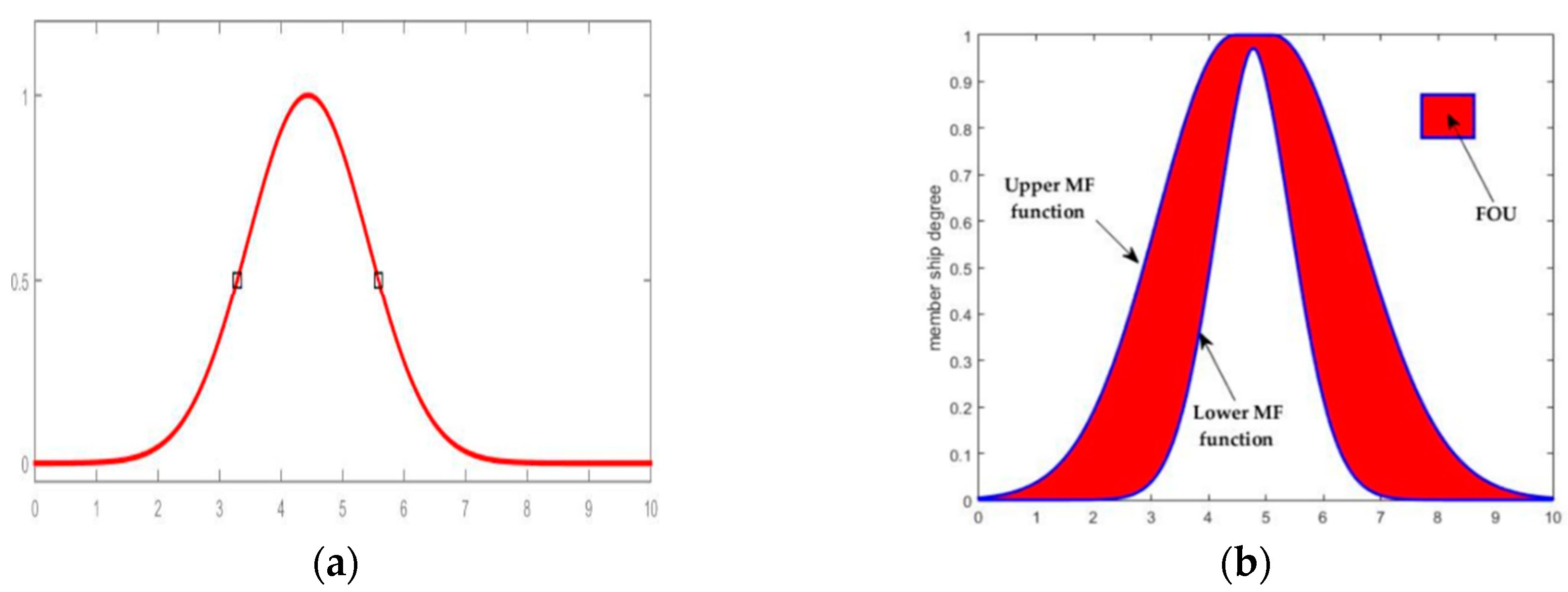
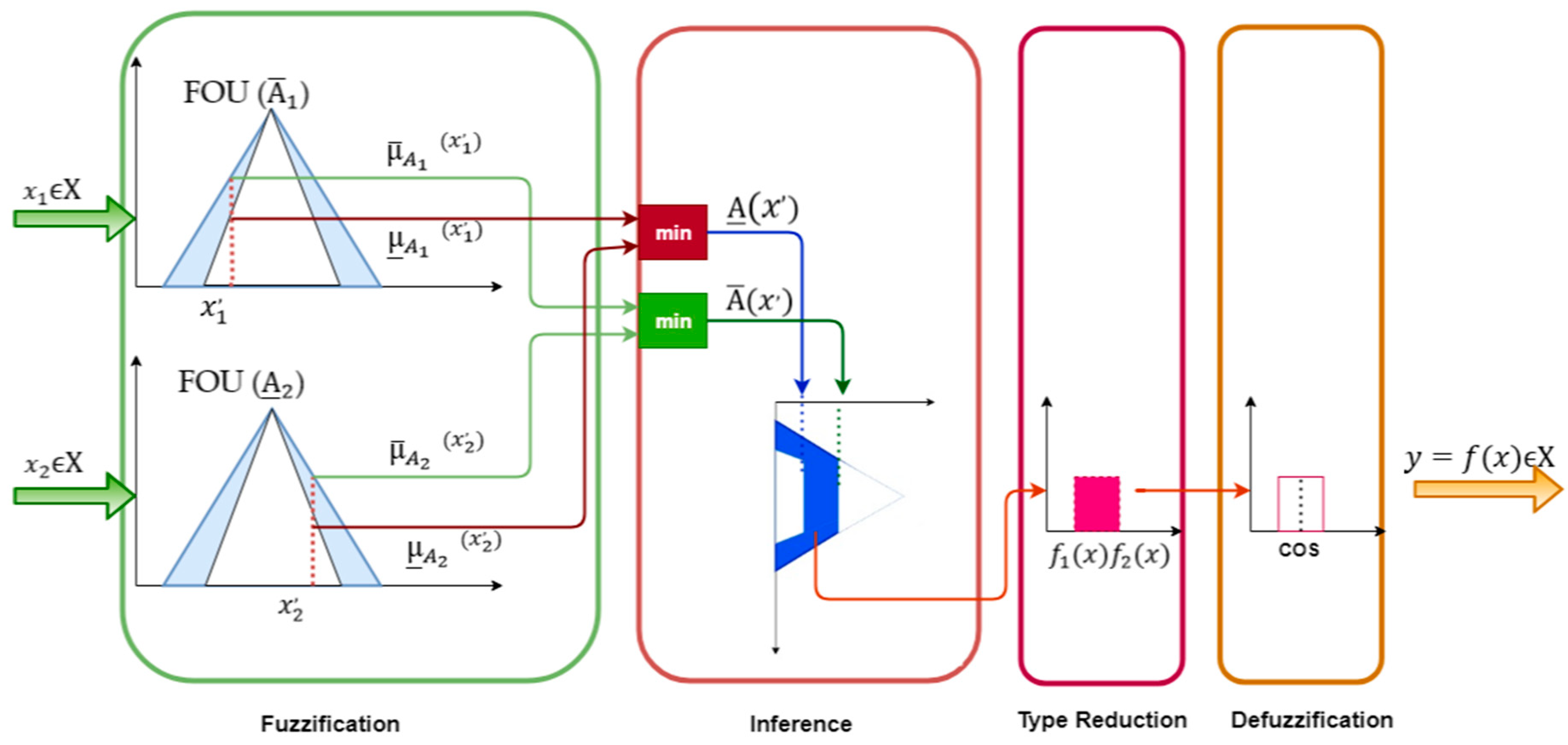
6. Interval Type-2 Fuzzy Logic System
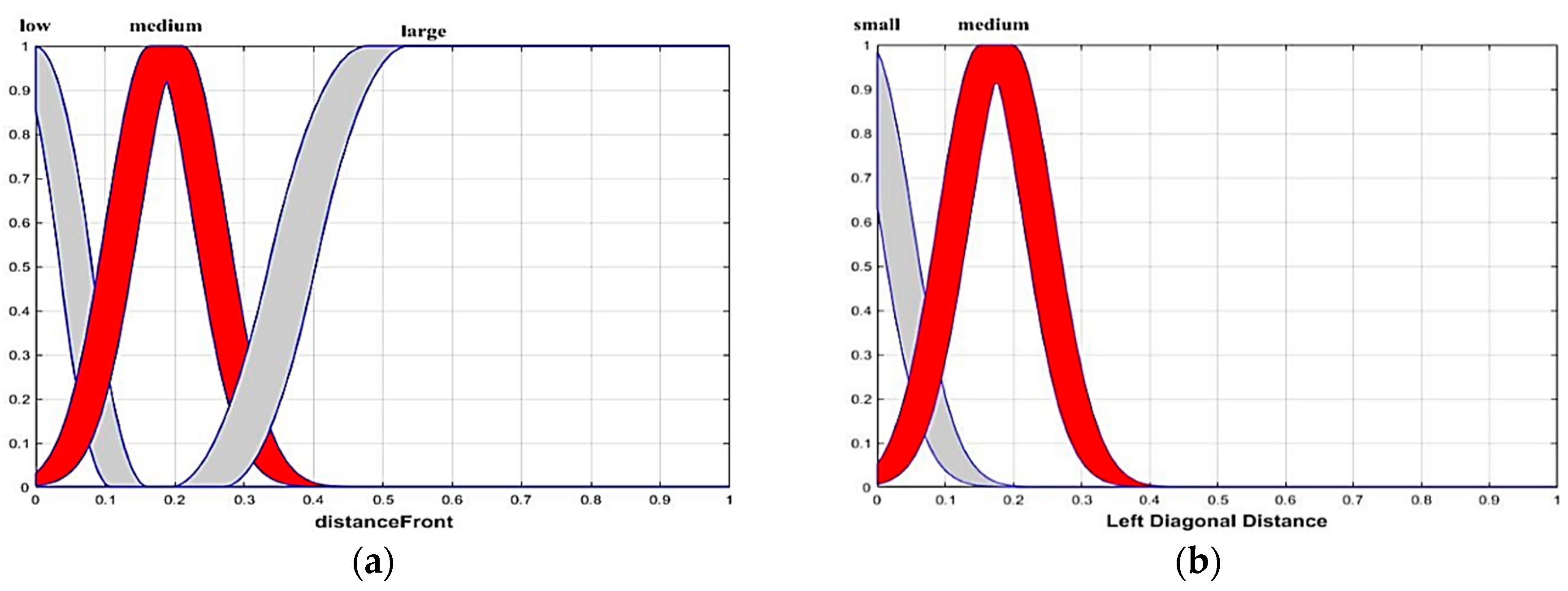
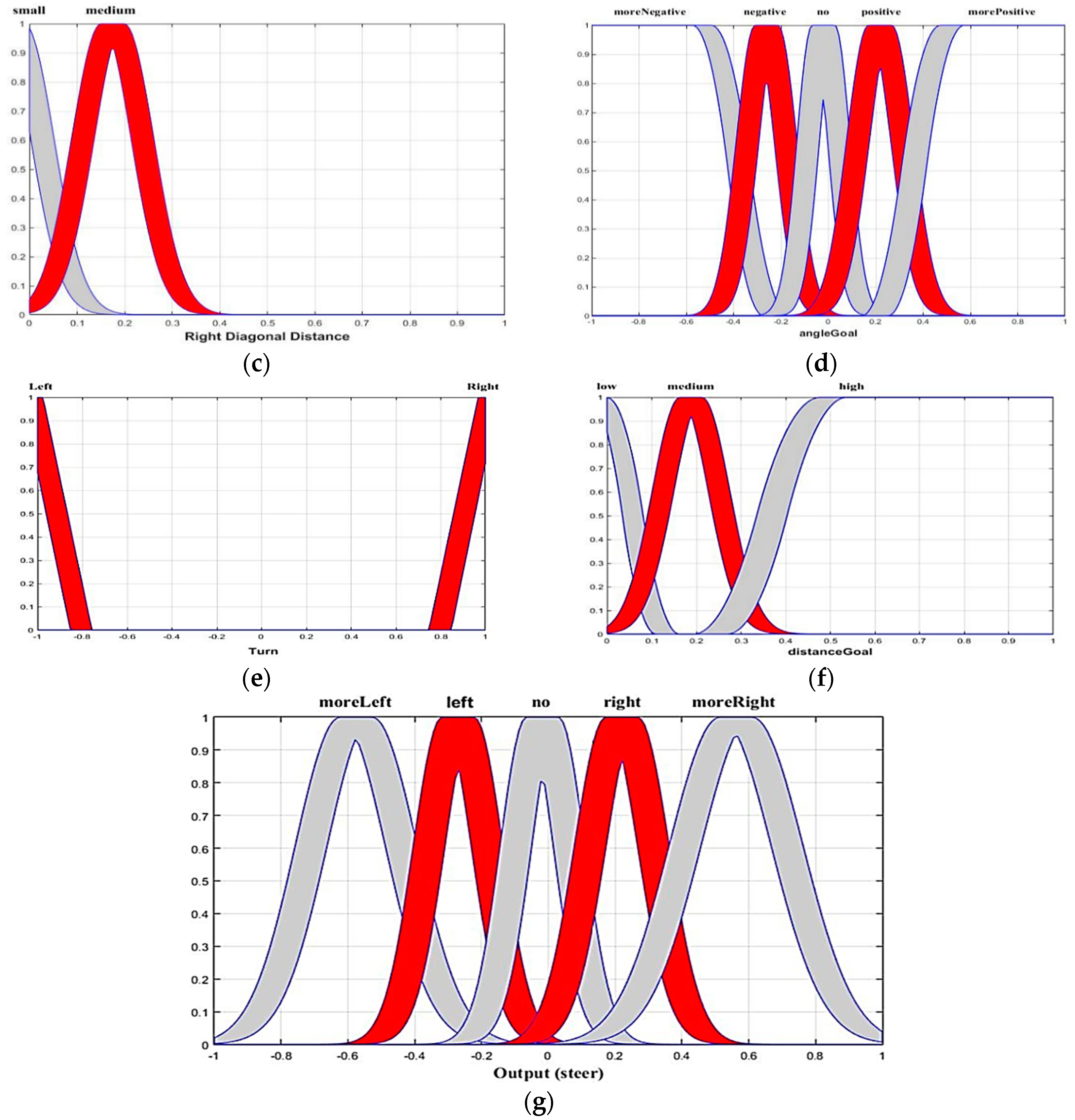
The design and theoretical basis of the type-2 fuzzy model for mobile robot path planning has been presented. This is intended to provide the basic concepts needed to understand the algorithm using input variables that were obtained in Section 3 and rules on which to base the value of output system determination. In its robustness for controlling nonlinear systems with variation and uncertainties, the fuzzy type-2 method has proven to be a strong tool for controlling complex systems [55,56,57,58,59]. The concept of the type-2 fuzzy set was introduced by Zadeh [60,61]. The presence of uncertainties in nonlinear system control uses the highest and lowest values of the parameters, extending the type-1 fuzzy method (Figure 4a) to type-2 (Figure 4b). Uncertainty is a characteristic of information, which may be incomplete, inaccurate, undefined, inconsistent, and so on. The uncertainty is represented by a region called the footprint of uncertainty (FOU). This is a bounded region that uses an upper and lower type-1 membership function.
An interval type-2 fuzzy set denoted by A ˜ is expressed in Equation (6) or (7).
A ˜ = { ( x , y ) , μ A ˜ ( x , y ) | x X , u J x [ 0   1 ] }
Hence, μ A ˜ ( x , u ) = 1 , u J x [ 0   1 ] is considered as an interval type-2 membership function, as shown in Figure 5.
A ˜ = x X u J x 1 / ( x , u )   J x [ 0   1 ]
where donate the union of all acceptable x and u . An IT2FIS is defined in terms of an upper membership function with μ ¯ A ˜ ( x ) and a lower membership function with μ ¯ A ˜ ( x ) . J x is just the interval of [ μ ¯ A ˜ ( x ) , μ ¯ A ˜ ( x ) ] . A type-2 FIS is characterized by IF-THEN rules, where the antecedent and consequent sets are type-2. To design a type-2 fuzzy controller, it is necessary to know the block structure used with type-1, because the basic blocks used are the same as those used with type-1. As seen in Figure 5, a type-2 FLS includes a fuzzifier, a rule base, a fuzzy inference engine, and an output processor. The output processor includes a type-reducer and defuzzifier. The type-reducer is the main distinctive point between type-1 and type-2 fuzzy systems. A type-1 fuzzy set output is generated (from the type-reducer) or a crisp number is generated (from the defuzzifier) [59]. The type reducer is added because of its association with the nature of the membership grades of the elements [62].

6.1. Fuzzifier

In this case, the inputs of the fuzzy set convert into suitable linguistic variables. The membership functions consist of one or several types-2 fuzzy sets. A numerical vector x of the fuzzifier maps converts into a type-2 set A ˜ . The outputs of the type-2 fuzzy sets are considered a singleton. In a singleton fuzzification, the inputs are crisp values on nonzero membership.
In these experiments we consider four inputs. These are angle to goal ( θ e ), distance from target (DT), distances from obstacles (DL, F, DR) and turn to avoid obstacle (TO). Figure 6 illustrates the block diagram of these parameters.
The angle to the target is the angle at which the robot is required to rotate to reach the target. The angle changes range from −180 to +180. The distance from the goal is normalized to lie between 0 and 1 and is multiplied by a constant that is between the robot and goal position. Similarly, the distance between the nearest obstacles in the direction in which the robot moves is the distance from the obstacle. This distance is also normalized between 0 and 1 [20]. The movement angle of the robot on the obstacle-free path is taken as the angle of robot direction rotation. This is the measure between robot and obstacle. There is a single output that measures the turning angle along with the direction. These values are important when creating the functions of the physical. The bounded region that uses an upper and lower type-1 membership function (MF) is the FOU. Uncertainty is a characteristic of information, which may be incomplete, inaccurate, undefined, inconsistent and so on. Primary MFs with uncertain standard deviation and uncertain mean are popular FOUs for a Gaussian because of their parsimony and differentiability. A Gaussian is important when a derivative-based optimization algorithm is used to optimize MF parameters during the design of an interval type-2 fuzzy system. Gaussian MFs are arguably favorable for this situation. The geometry of the membership functions is arbitrarily selectable and the aforementioned features of the Gaussian function are preferred. The membership functions of the different inputs and outputs are given in Figure 7.

6.2. Fuzzy Inference Engine

The inference engine is an interface that processes input values according to certain rules and produces output type-2 fuzzy sets. That is, it combines or arranges a center between the input and the output. Figure 5 shows a graphical representation of the relationship between input and output. It is necessary to compute the intersection and union of type-2 sets and implement compositions of type-2 relations. The desired behavior is defined by a set of linguistic rules. It is necessary to set the rules adequately to achieve the desired result. For instance, a type-2 fuzzy logic with p inputs ( x 1 X 1 , x p X p ) and one output ( y Y ) with M rules has the following form.
R :   IF   x 1   is   F ˜ 1   and   x p   is   F ˜ p   THEN   y   is     G   ˜ ,   = 1 M
The knowledge bases for each controller consist of 25 rules related to the robot direction which are presented in Table 1. The position of the rules created in the knowledge base in the coordinate plane will be shown graphically.
In these experiments, we used type-2 fuzzy sets and a minimum t-norm operation. The rule firing strength F i ( x ) for crisp input vector is given by the type-1 fuzzy set
F l ( x ) = [ f _   l ( x ) ,   f ¯ l ( x ) ] [ f _   l ,   f ¯ l ]
where f _   l   and   f ¯ l are the lower and upper firing degrees of the l th rule, computed using Equations (9) and (10)
f _   l ( x ) = μ ¯ F ˜ 1 l ( x 1 ) μ ¯ F ˜ p l ( x p )
f ¯ l ( x ) = μ ¯ F ˜ 1 l ( x 1 ) μ ¯ F ˜ 1 l ( x p )
in which represents the t-norm, which is the p r o d operator in these equations.

6.3. Type Reducer

All fuzzy logic systems have to produce a crisp output in order to have a practical application. The single combined type-2 fuzzy set has to be processed with the type reducer and the defuzzifier. Type-1 fuzzy set output is generated with the type reducer method. These outputs are converted into the crisp output through the defuzzifier. The defuzzifier combines the output sets to obtain a single output using one of the existing type reduction methods. The type reducer was proposed by Karnik and Mendel [58,63,64,65]. Many methods can be used for type reduction. Centroid type reduction, height type reduction, and center of set are the most commonly used. In these experiments a center of sets (cos) type reduction method was used. The expression of this method can be written as Equation (11).
Y c o s ( x ) = [ y l , y r ] = y 1 [ y l 1 , y r 1 ] y 1 [ y l M , y r M ] f 1 [ f _   1 , f ¯ 1 ] f M [ f _   M   , f ¯ M ] / i = 1 M f i y i i = 1 M f i
This center of sets is completely characterized by its left and right end points. The consequent set of the interval type-2 determined those two endpoints ( y l , y r ). If the values of f i and y i which are associated with y l are donated to f l i and y l i , respectively, and the values of f i and y i which are associated with y r are donated to f r i and y r i respectively, f _   i   and   f ¯ i are the lower and upper firing degrees of the i th rule and and M is the number of fired rules. These points are given in Equations (12) and (13).
y l = i = 1 M f l i y l i i = 1 M f l i
y r = i = 1 M f r i y r i i = 1 M f r i
The interval type-2 fuzzy system’s outputs are represented with y l and y r .

6.4. Defuzzifier

The interval fuzzy set Y cos ( x ) variables obtained from the type reducer are defuzzified and the average of y l and y r are used to defuzzify the output of an interval singleton type-2 fuzzy logic system. The equation is written as
y ( x ) = y l + y r 2

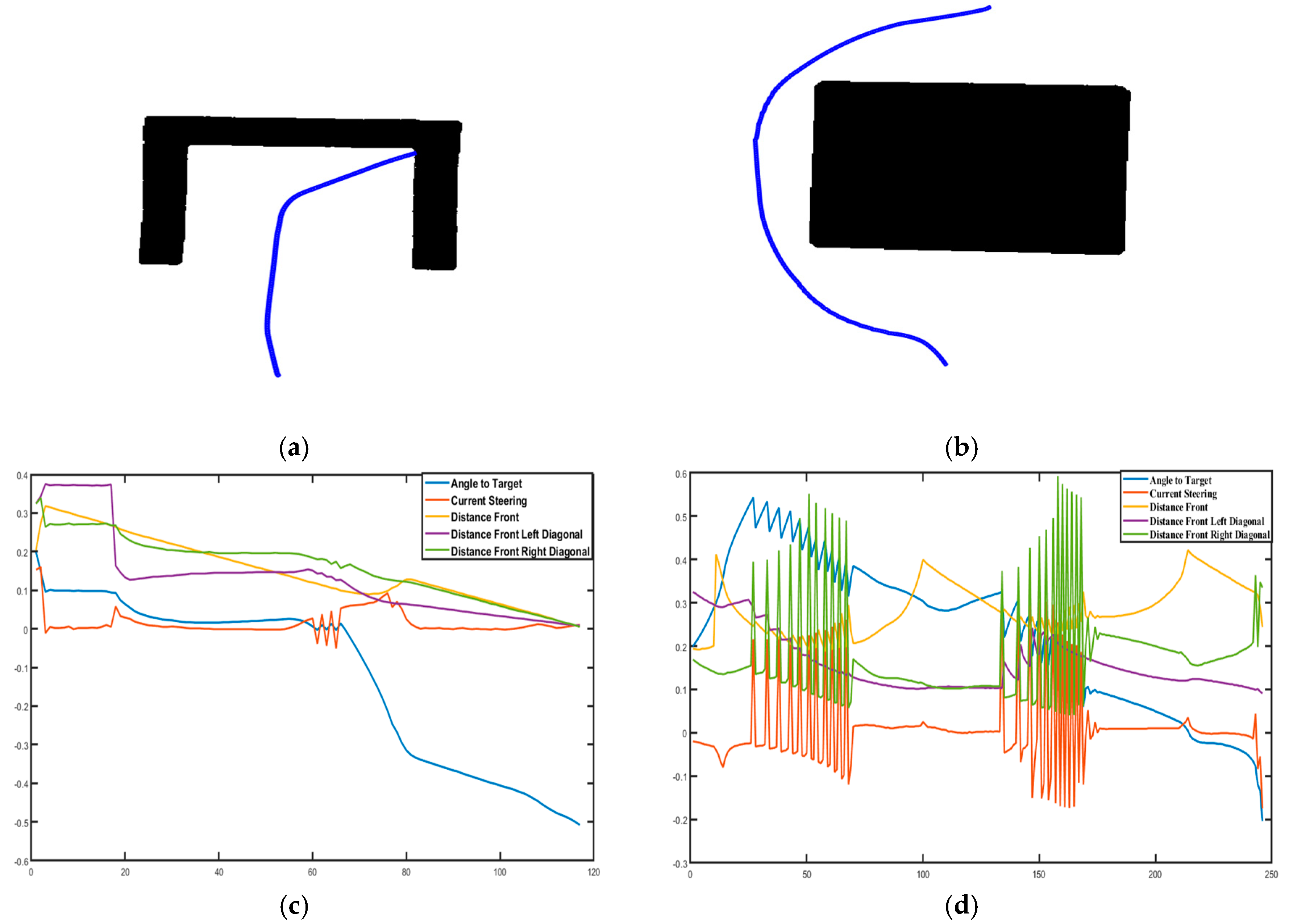
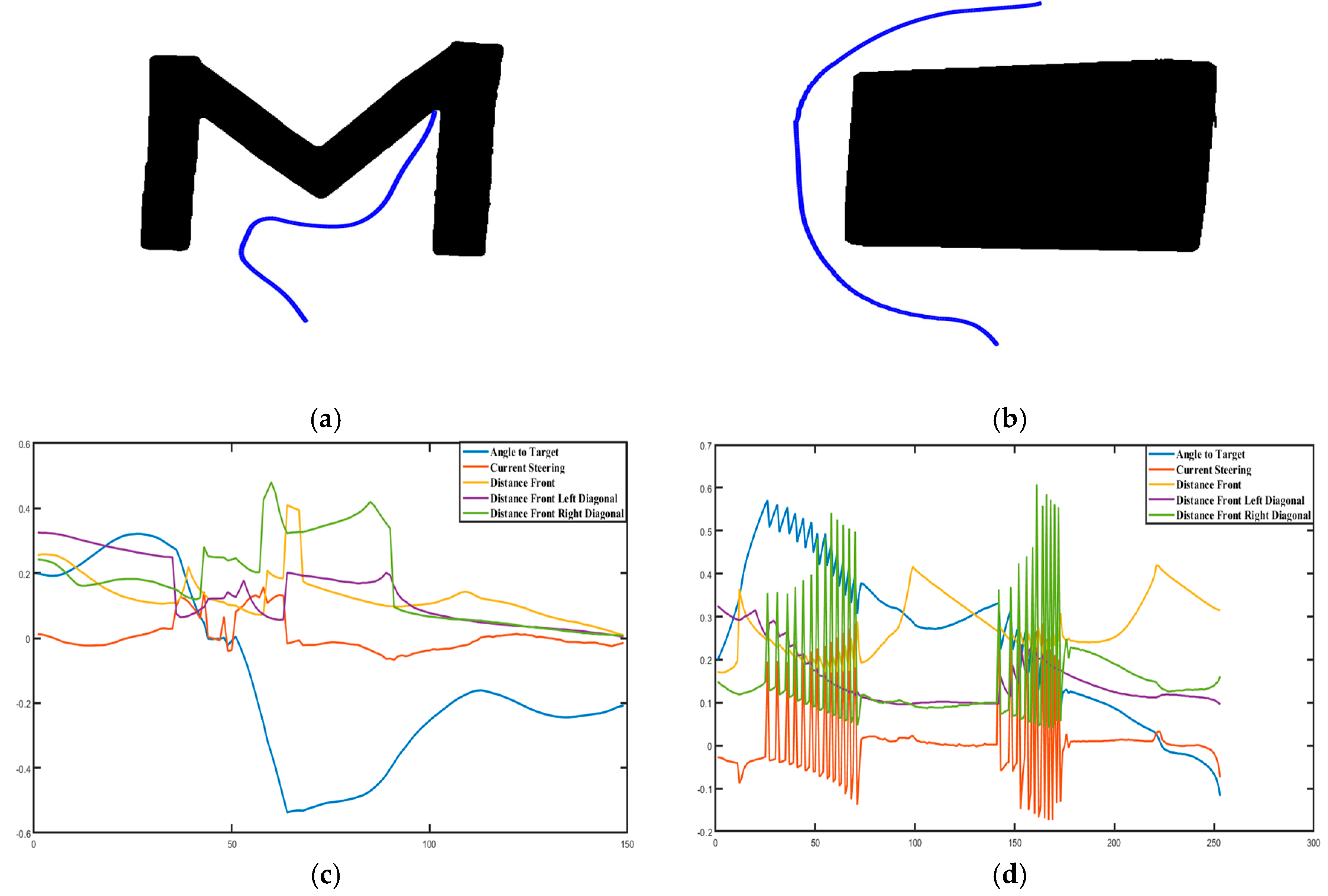
7. Experimental Result

The main contribution of this work is its developing a visual-servoing-based control system for mobile robot path planning using IT2FIS and comparing the proposed method with other path planning algorithms. Many experiments have been done to verify the algorithm and to ensure that the simulation is really applicable based on the experimental results. The robot location, orientation, and target location were detected by using a shape-adapted mean shift algorithm. The object coordinate system was chosen as the center point of the geometric center. We have shown that this algorithm can be easily deployed on a real robot for path planning based on the results of the experimental study. The overall algorithms were implemented and tested on a 2.40 GHz dual-core system with 16GB of RAM using a combination of LabVIEW and MATLAB. To fully test the behavior of the algorithm, we performed a large number of experiments on the different maps. The results of the two experimental maps are given in Figure 8 and Figure 9. As shown in the figures, the image processing steps of the map for the robot path plan are shown. The obstacles in the map are depicted as black regions and the obstacle-free path is depicted as the white region. The obstacle placed between the robot and target is of a difficult shape and includes the possibility of local minimum problems. To overcome this problem a convex hull technique was applied. With this technique, we observed that the robot’s path leads easily to the target. IT2FIS methods could smoothly manage the path generation process and avoid obstacle on the way. The results of the two scenarios are shown below.
The first scenario (Figure 8) shows how the robot map is derived from the image algorithm for the purpose of calculating the unimpeded path for a real map. The objects on the map are the robot (white object), target (red object), and an obstacle (green object). The algorithm displays the map in the binary image. The first image contains all objects (robot, target, and obstacle) and only the obstacle is present in the last image. There are also some morphological processes in the intermediate processes. The bounding box around the robot and robot location information is determined from the first image. In order to obtain the final image, morphological processes and a convex hull technique were applied to the obstacle to resize it (see Figure 8 and Figure 9).
The system was tested under two different variable maps. First, it was tested under normal conditions (Figure 10a and Figure 11a). The system was tested to ensure that the robot monitors sharp angles in case of disabilities with irregular lines and distortions. The main purpose of this test was to control robot behavior on the map where the visual servo controller contains obstacles of variable lengths and sharp angles (Figure 10a and Figure 11a). As shown in these figures, the generated robot path is shown from its initial position to its endpoint (collision point). The calculated data at each point on the path that is obtained during the path generation is shown graphically in Figure 10c and Figure 11c. Secondly, in the dynamic map which formed under the changed conditions, it is shown that the robot goes to the target without colliding with obstacles by softening the boundary lines of obstacles in the working area and by filling the spaces with the convex hull method. This experiment tests the algorithm’s ability to establish a safe path without containing collisions with obstacles in the map shown in Figure 10b and Figure 11b. Here, the shortest path generation is not the priority; it is actually the safest path which is desired. It can be observed that the robot’s path is easily oriented towards the target. It manages to overcome obstacles of all dimensions and shapes that were in its way. The path generated is quite convenient and the algorithmic result is given in Figure 10b and Figure 11b. The data obtained during the path generation is shown graphically in Figure 10d and Figure 11d.
In Table 2, we aimed to compare the proposed method with other algorithms which are used for navigation and obstacle avoidance. Each algorithm was executed in two scenarios and their performance illustrated in Table 2 for the first scenario. Each method was executed under the same conditions (environmental, directional, and initial and target positions). The comparison table includes the path length and algorithm processing time. In this study, the processing time was taken into consideration. It is obvious from the results reported in Table 2 that the IT2FIS method performed better than the others.

8. Conclusions

The computational complexity of vision algorithms and the cost of sensors are the most critical aspects for real time applications. Vision sensors are a good cost-effective solution for vision-based navigation. The system is realized by the integration of vision-based obstacle detection methods and soft-computing-based path planning systems. In this paper, we propose an effective visual-servoing-based global path planning system using interval type-2 FIS and comparisons with various path planning algorithms. The limitations in conventional methods in terms of accuracy and efficiency were the main motivations behind this study. A novel distance estimation method using overhead camera systems was used which employed scale parameters from an IT2FIS algorithm. We tested new frameworks for the evolutionary algorithm for various scenarios. In our experiments, we observed that the algorithm failed when it encountered obstacles with complicated dimensions and sharp edge. To overcome these problems, we proposed a new algorithm. The algorithm merged image processing morphological operation with a convex-hull method to generate the desired collision-free path. The aim was to design an intelligent controller based on visual servoing using IT2FIS techniques. It is important to design a robust controller for mobile robot path planning with good performance in spite of the lack of information about the robot’s surrounding environment models. There were significant changes due to appearance-based environmental factors like constant illumination and lighting condition factors. To overcome these problems the proposed system was adopted, which combined IT2FIS and an overhead camera-based structure. The proposed system presented good performance and robustness through various applied scenarios. Comparisons with other algorithms have also been examined and the results have been shown. The provided simulation results demonstrated that our proposed approach acts successfully and is able to generate paths easily with good performances using IT2FIS. Thus the controllers’ outputs are much smoother and considerably safer paths are generated.

Author Contributions

Conceptualization, M.D. and A.F.K.; methodology, M.D.; software, M.D.; validation, M.D., A.F.K. and O.C., formal analysis, M.D.; investigation, M.D.; resources, O.C. and M.D.; data curation, M.D.; writing—original draft preparation, M.D. and A.F.K; writing—review and editing, O.C. and M.D.; visualization, M.D. and A.F.K.; supervision, O.C.; funding acquisition, M.D.

Funding

This research was funded by TUBITAK-BIDEB under grant 2214/A.

Conflicts of Interest

The authors declare that there is no conflict of interest regarding the publication of this paper.

References

  1. Siegwart, R.; Nourbakhsh, I.R.; Scaramuzza, D.; Arkin, R.C. Introduction to Autonomous Mobile Robots; MIT Press: Cambridge, MA, USA, 2011. [Google Scholar]
  2. Torshizi, A.D.; Hossein, M.; Zarandi, F.; Zakeri, H. On type-reduction of type-2 fuzzy sets: A review. Appl. Soft Comput. 2015, 7, 614–627. [Google Scholar] [CrossRef]
  3. Sepúlveda, R.; Montiel, O.; Castillo, O.; Melin, P. Embedding a high speed interval type-2 fuzzy controller for a real plant into an FPGA. Appl. Soft Comput. 2011, 12, 988–998. [Google Scholar] [CrossRef]
  4. Mbede, J.B.; Melingui, A.; Zobo, B.E.; Merzouki, R.; Bouamama, B.O. zSlices based type-2 fuzzy motion control for autonomous robotino mobile robot. In Proceedings of the 2012 IEEE/ASME 8th IEEE/ASME International Conference on Mechatronic and Embedded Systems and Applications, Suzhou, China, 8–10 July 2012; pp. 63–68. [Google Scholar]
  5. Cortes-Rios, J.C.; Gomez-Ramirez, E.; Ortiz-De-La-Vega, H.A.; Castillo, O.; Melin, P. Optimal design of interval type 2 fuzzy controllers based on a simple tuning algorithm. Appl. Soft Comput. 2014, 23, 270–285. [Google Scholar] [CrossRef]
  6. Maldonado, Y.; Castillo, O.; Melin, P. Particle swarm optimization of interval type-2 fuzzy systems for FPGA applications. Appl. Soft Comput. 2013, 13, 496–508. [Google Scholar] [CrossRef]
  7. Castillo, O.; Melin, P.; Pedrycz, W. Design of interval type-2 fuzzy models through optimal granularity allocation. Appl. Soft Comput. 2011, 11, 5590–5601. [Google Scholar] [CrossRef]
  8. Castillo, O.; Melin, P. A review on the design and optimization of interval type-2 fuzzy controllers. Appl. Soft Comput. 2011, 12, 1267–1278. [Google Scholar] [CrossRef]
  9. Olivas, F.; Valdez, F.; Castillo, O.; Gonzalez, C.I.; Martinez, G.; Melin, P. Ant colony optimization with dynamic parameter adaptation based on interval type-2 fuzzy logic systems. Appl. Soft Comput. J. 2017, 53, 74–87. [Google Scholar] [CrossRef]
  10. Gonzalez, C.I.; Melin, P.; Castro, J.R.; Castillo, O.; Mendoza, O. Optimization of interval type-2 fuzzy systems for image edge detection. Appl. Soft Comput. 2016, 47, 631–643. [Google Scholar] [CrossRef]
  11. Liao, T.W. A procedure for the generation of interval type-2 membership functions from data. Appl. Soft Comput. J. 2017, 52, 925–936. [Google Scholar] [CrossRef]
  12. Ider, M. Type-2 fuzzy logic control for a mobile robot tracking a moving target. Med. J. Model. Simul. 2015, 3, 57–65. [Google Scholar]
  13. Lozano-Pérez, T.; Wesley, M.A. An algorithm for planning collision-free paths among polyhedral obstacles. Commun. ACM 1979, 22, 560–570. [Google Scholar] [CrossRef]
  14. Xue, Y.; Sun, J.-Q. Solving the Path Planning Problem in Mobile Robotics with the Multi-Objective Evolutionary Algorithm. Appl. Sci. 2018, 8, 1425. [Google Scholar] [CrossRef]
  15. Pamučar, D.; Ljubojević, S.; Kostadinović, D.; Đorović, B. Cost and risk aggregation in multi-objective route planning for hazardous materials transportation—A neuro-fuzzy and artificial bee colony approach. Expert Syst. Appl. 2016, 65, 1–15. [Google Scholar] [CrossRef]
  16. Pamucar, D.; Cirovic, G. Vehicle Route Selection with an Adaptive Neuro Fuzzy Inference System in Uncertainty Conditions. Decis. Mak. Appl. Manag. Eng. 2018, 1, 13–37. [Google Scholar] [CrossRef]
  17. Pamučar, D.; Vasin, L.; Atanasković, P.; Miličić, M. Planning the City Logistics Terminal Location by Applying the Green p -Median Model and Type-2 Neurofuzzy Network. Comput. Intell. Neurosci. 2016, 2016, 1–15. [Google Scholar] [CrossRef]
  18. Ng, K.C.; Trivedi, M.M. A neuro-fuzzy controller for mobile robot navigation and multirobot convoying. IEEE Trans. Syst. Man Cybern. Part B Cybern. 1998, 28, 829–840. [Google Scholar] [CrossRef] [Green Version]
  19. Bakdi, A.; Hentout, A.; Boutami, H.; Maoudj, A.; Hachour, O.; Bouzouia, B. Optimal path planning and execution for mobile robots using genetic algorithm and adaptive fuzzy-logic control. Rob. Auton. Syst. 2017, 89, 95–109. [Google Scholar] [CrossRef]
  20. Kala, R.; Shukla, A.; Tiwari, R. Fusion of probabilistic A* algorithm and fuzzy inference system for robotic path planning. Artif. Intell. Rev. 2010, 33, 307–327. [Google Scholar] [CrossRef]
  21. Duchoň, F.; Babinec, A.; Kajan, M.; Beňo, P.; Florek, M.; Fico, T.; Jurišica, L. Path planning with modified A star algorithm for a mobile robot. Procedia Eng. 2014, 96, 59–69. [Google Scholar] [CrossRef]
  22. Stentz, A. Optimal and Efficient Path Planning for Partially Known Environments. In Intelligent Unmanned Ground Vehicles; Springer: Boston, MA, USA, 1997; pp. 203–220. [Google Scholar] [Green Version]
  23. Al-Taharwa, I.; Sheta, A.; Al-Weshah, M. A mobile robot path planning using genetic algorithm in static environment. J. Comput. Sci. 2008, 4, 341–344. [Google Scholar] [CrossRef]
  24. Hu, Y.; Yang, S.X. A knowledge based genetic algorithm for path planning of a mobile robot. In Proceedings of the IEEE International Conference on Robotics and Automation, New Orleans, LA, USA, 26 April–1 May 2004. [Google Scholar]
  25. Yüksel, T.; Sezgin, A. An Implementation of Path Planning Algorithms for Mobile Robots on A Grid Based Map. In Proceedings of the 4th International Conference on Electrical and Electronics Engineering (ELECO 2005), Bursa, Turkey, 7–11 December 2005. [Google Scholar]
  26. Lee, C.Y. An Algorithm for Path Connections and Its Applications. IRE Trans. Electron. Comput. 1961, 3, 346–365. [Google Scholar] [CrossRef]
  27. Anderson, J.B.; Mohan, S. Sequential Coding Algorithms: A Survey and Cost Analysis. IEEE Trans. Commun. 1984, 32, 169–176. [Google Scholar] [CrossRef]
  28. Rimon, E.; Koditschek, D.E. Exact Robot Navigation using Artificial Potential Functions. IEEE Trans. Robot. Autom. 1992, 8, 501–508. [Google Scholar] [CrossRef]
  29. Montiel, O.; Orozco-Rosas, U.; Sepúlveda, R. Path planning for mobile robots using Bacterial Potential Field for avoiding static and dynamic obstacles. Expert Syst. Appl. 2015, 42, 5177–5191. [Google Scholar] [CrossRef]
  30. Dönmez, E.; Kocamaz, A.F.; Dirik, M. Bi-RRT path extraction and curve fitting smooth with visual based configuration space mapping. In Proceedings of the 2017 International Artificial Intelligence and Data Processing Symposium (IDAP), Malatya, Turkey, 16–17 September 2017; pp. 1–5. [Google Scholar]
  31. LaValle, S.M.; Kuffner, J.J. Randomized kinodynamic planning. Int. J. Rob. Res. 2001, 20, 378–400. [Google Scholar] [CrossRef]
  32. Chandak, A.; Gosavi, K.; Giri, S.; Agrawal, S.; Kulkarni, P. Path Planning for Mobile Robot Navigation using Image Processing. Int. J. Sci. Eng. Res. 2013, 4, 1490–1496. [Google Scholar]
  33. Ziaei, Z.; Oftadeh, R.; Mattila, J. Vision-based path coordination for multiple mobile robots with four steering wheels using an overhead camera. In Proceedings of the IEEE International Conference on Advanced Intelligent Mechatronics (AIM), Busan, South Korea, 7–11 July 2015; pp. 261–268. [Google Scholar]
  34. Elsheikh, E.A.; El-Bardini, M.A.; Fkirin, M.A. Dynamic path planning and decentralized FLC path following implementation for WMR based on visual servoing. In Proceedings of the 3rd MEC International Conference on Big Data and Smart City (ICBDSC), Muscat, Oman, 15–16 March 2016; pp. 148–154. [Google Scholar]
  35. Ziaei, Z.; Oftadeh, R.; Mattila, J. Global path planning with obstacle avoidance for omnidirectional mobile robot using overhead camera. In Proceedings of the IEEE International Conference on Mechatronics and Automation, Tianjin, China, 3–6 August 2014; pp. 697–704. [Google Scholar]
  36. Chen, C.H.L.; Lee, M.F.R. Global path planning in mobile robot using omnidirectional camera. In Proceedings of the International Conference on Consumer Electronics, Communications and Networks (CECNet), Xianning, China, 16–18 April 2011; pp. 4986–4989. [Google Scholar]
  37. Dönmez, E.; Kocamaz, A.F.; Dirik, M. A Vision-Based Real-Time Mobile Robot Controller Design Based on Gaussian Function for Indoor Environment. Arab. J. Sci. Eng. 2017, 43, 7127–7142. [Google Scholar] [CrossRef]
  38. Astudillo, L.; Melin, P.; Castillo, O. Optimization of type-2 and type-1 fuzzy tracking controllers for an autonomous mobile robot under perturbed torques by means of a chemical optimization paradigm. In Studies in Fuzziness and Soft Computing; Springer: Berlin/Heidelberg, Germany, 2013. [Google Scholar]
  39. Nurmaini, S.; Zaiton, S.; Norhayati, D. An embedded interval type-2 neuro-fuzzy controller for mobile robot navigation. In Proceedings of the IEEE International Conference on Systems, Man and Cybernetics, San Antonio, TX, USA, 11–14 October 2009. [Google Scholar]
  40. Elsheikh, E.A.; Fkirin, M.A. Practical path planning and path following for a non- holonomic mobile robot based on visual servoing. In Proceedings of the IEEE Information Technology, Networking, Electronic and Automation Control Conference, Chongqing, China, 20–22 May 2016. [Google Scholar]
  41. Dirik, M.; Kocamaz, A.F.; Dönmez, E. Visual servoing based path planning for wheeled mobile robot in obstacle environments. In Proceedings of the International Artificial Intelligence and Data Processing Symposium (IDAP), Malatya, Turkey, 16–17 September 2017. [Google Scholar]
  42. Omrane, H.; Masmoudi, M.S.; Masmoudi, M. Fuzzy Logic Based Control for Autonomous Mobile. Comput. Intell. Neurosci. 2016, 2016, 1–10. [Google Scholar] [CrossRef]
  43. Pandey, K.K.; Mohanty, P.K.; Parhi, D.R. Real time navigation strategies for webots using fuzzy controller. In Proceedings of the IEEE 8th International Conference on Intelligent Systems and Control (ISCO), Coimbatore, India, 10–11 January 2014; pp. 10–16. [Google Scholar]
  44. Dirik, M.; Castillo, O.; Kocamaz, A.F. Gaze-Guided Control of an Autonomous Mobile Robot Using Type-2 Fuzzy Logic. Appl. Syst. Innov. 2019, 2, 14. [Google Scholar] [CrossRef]
  45. Garcia, M.A.P.; Montiel, O.; Castillo, O.; Sepúlveda, R.; Melin, P. Path planning for autonomous mobile robot navigation with ant colony optimization and fuzzy cost function evaluation. Appl. Soft Comput. 2009, 9, 1102–1110. [Google Scholar] [CrossRef]
  46. Lu, X.G.; Liu, M.; Liu, J.X. Design and Optimization of Interval Type-2 Fuzzy Logic Controller for Delta Parallel Robot Trajectory Control. Int. J. Fuzzy Syst. 2017, 19, 190–206. [Google Scholar] [CrossRef]
  47. Baklouti, N.; John, R.; Alimi, A. Interval Type-2 Fuzzy Logic Control of Mobile Robots. J. Intell. Learn. Syst. Appl. 2012, 4, 291–302. [Google Scholar] [CrossRef]
  48. Liang, Q.; Mendel, J. Interval Type-2 Fuzzy Logic Systems: Theory and Design. IEEE Trans. Fuzzy Syst. 2000, 8, 535–550. [Google Scholar] [CrossRef]
  49. Gaxiola, F.; Melin, P.; Valdez, F.; Castro, J.R.; Castillo, O. PSO with Dynamic Adaptation of Parameters for Optimization in Neural Networks with Interval Type-2 Fuzzy Numbers Weights. Axioms 2019, 8, 14. [Google Scholar] [CrossRef]
  50. Pamučar, D.; Atanasković, P.; Miličić, M. Modeling of fuzzy logic system for investment management in the railway infrastructure. Tehnicki Vjesnik/Technical Gazette 2015, 22. [Google Scholar] [CrossRef] [Green Version]
  51. Pamucar, D.; Bozanic, D.; Komazec, N. Risk Assessment of Natural Disasters Using Fuzzy Logic System of Type 2. Manag. J. Theory Pract. Manag. 2016, 21, 23–33. [Google Scholar]
  52. Guzmán, J.C.; Miramontes, I.; Melin, P.; Prado-Arechiga, G. Optimal Genetic Design of Type-1 and Interval Type-2 Fuzzy Systems for Blood Pressure Level Classification. Axioms 2019, 8, 8. [Google Scholar] [CrossRef]
  53. Martinez, R.; Castillo, O.; Aguilar, L.T. Optimization of interval type-2 fuzzy logic controllers for a perturbed autonomous wheeled mobile robot using genetic algorithms. Inf. Sci. 2009, 179, 2158–2174. [Google Scholar] [CrossRef]
  54. Castillo, O.; Amador-Angulo, L.; Castro, J.R.; Garcia-Valdez, M. A comparative study of type-1 fuzzy logic systems, interval type-2 fuzzy logic systems and generalized type-2 fuzzy logic systems in control problems. Inf. Sci. 2016, 354, 257–274. [Google Scholar] [CrossRef]
  55. Bernal, E.; Castillo, O.; Soria, J.; Valdez, F. Optimization of Fuzzy Controller Using Galactic Swarm Optimization with Type-2 Fuzzy Dynamic Parameter Adjustment. Axioms 2019, 8, 26. [Google Scholar] [CrossRef]
  56. Mendel, J.M. Advances in type-2 fuzzy sets and systems. Inf. Sci. 2007, 177, 84–110. [Google Scholar] [CrossRef]
  57. Mendel, J.M.; John, R.I.B. Type-2 fuzzy sets made simple. IEEE Trans. Fuzzy Syst. 2002, 10, 117–127. [Google Scholar] [CrossRef] [Green Version]
  58. Castillo, O.; Melin, P. Type-2 fuzzy logic systems. In Briefs in Applied Sciences and Technology; Springer: Berlin, Germany, 2012. [Google Scholar]
  59. Castillo, O.; Melin, P.; Kacprzyk, J.; Pedrycz, W. Type-2 Fuzzy Logic: Theory and Applications. In Proceedings of the EEE International Conference on Granular Computing (GRC 2007), Fremont, CA, USA, 2–4 November 2007; p. 145. [Google Scholar]
  60. Zadeh, L.A. A fuzzy -algorithmic approach to the definition of complex or imprecise concepts. Int. J. Man-Mach. Stud. 1976, 8, 249–291. [Google Scholar] [CrossRef]
  61. Zadeh, L.A. The concept of a linguistic variable and its application to approximate reasoning-III. Inf. Sci. 1975, 9, 43–80. [Google Scholar] [CrossRef]
  62. Castillo, O.; Melin, P. Hybrid intelligent systems for time series prediction using neural networks, fuzzy logic, and fractal theory. IEEE Trans. Neural Netw. 2002, 13, 1395–1408. [Google Scholar] [CrossRef]
  63. Karnik, N.N.; Mendel, J.M. Centroid of a type-2 fuzzy set. Inf. Sci. 2001, 132, 195–220. [Google Scholar] [CrossRef]
  64. Mendel, J.M.; John, R.I.; Liu, F. Interval Type-2 Fuzzy Logic Systems Made Simple. IEEE Trans. Fuzzy Syst. 2006, 14, 808–821. [Google Scholar] [CrossRef] [Green Version]
  65. Karnik, N.N.; Mendel, J.M.; Liang, Q. Type-2 Fuzzy Logic Systems. IEEE Trans. FUZZY Syst. 1999, 7, 16. [Google Scholar] [CrossRef]
Figure 1. System architecture of vision-based path planning for mobile robot. Legend: IT2FIS, interval type-2 fuzzy logic; DT, distance from target; LD, left diagonal; F, front; RD, right diagonal (distance from obstacles and robot path).
Axioms 08 00058 g001
Figure 2. (a) Image analysis steps and (b) structure and functionality of the vision algorithm.
Axioms 08 00058 g002
Figure 3. Tracking a virtual reference path (angle to goal (θ = θrθe).
Axioms 08 00058 g003
Figure 4. (a) Type-1 membership function and (b) type-2 membership function. Legend: FOU, footprint of uncertainty.
Axioms 08 00058 g004
Figure 5. Structure of a type-2 fuzzy logic system.
Axioms 08 00058 g005
Figure 6. Block diagram of fuzzy-based robot path planning.
Axioms 08 00058 g006
Figure 7. The membership functions (inputs: (af), output: (g)).
Axioms 08 00058 g007aAxioms 08 00058 g007b
Figure 8. Structure and functionality of vision algorithm (first scenario).
Axioms 08 00058 g008
Figure 9. Structure and functionality of vision algorithm (second scenario).
Axioms 08 00058 g009
Figure 10. Test results for the first scenario (Figure 8) (collision detection (a), convex hull applied image and safe path generated from the image (b), the variable obtained from Figure 9a path generation when the robot goes to the goal (c), the variable obtained from Figure 9b path generation when the robot goes to the goal (d)).
Axioms 08 00058 g010
Figure 11. Test results for the second scenario (Figure 10) (collision detection (a), convex hull applied image and safe path generated from the image (b), the variable obtained from Figure 11a path generation when the robot goes to the goal (c), the variable obtained from Figure 11b path generation when the robot goes to the goal (d)).
Axioms 08 00058 g011
Table 1. Rule base for robot wheel speed fuzzy controller. Legend: LD, distance front left diagonal; F, distance front; RD, distance front right diagonal; AG, angle to goal; DT, distance to target.
InputsOutput
LDFRDAGTurnDTDirection
1 low left moreLeft
2 medium left left
3 large left left
4 low right moreRight
5 medium right right
6 large right right
7small moreRight
8medium right
9 small moreLeft
10 medium left
11 negative lowmoreLeft
12 moreNegative lowmoreLeft
13 no lowno
14 positive lowmoreRight
15 morePositive lowmoreRight
16 negative mediumleft
17 no mediumno
18 positive mediumright
19 morePositive mediummoreRight
20 moreNegative highleft
21 negative highleft
22 no highno
23 positive highright
24 morePositive highright
25 moreNegative mediummoreLeft
Table 2. Comparison values between mobile robot path planning algorithms used in our experiments.
Path Planning Algoriths.Initial PositionTarget PositionPath LengthProces. Time (s)
Type-2 FIS (IT2FIS)[Xr,Yr] = [470, 900][Tx,Ty] = [550, 120]12451.8070
Type-1 FIS[Xr,Yr] = [470, 900][Tx,Ty] = [550, 120]14151.5781
APF[Xr,Yr] = [470, 900][Tx,Ty] = [550, 120]14371.6201
RRT[Xr,Yr] = [470, 900][Tx,Ty] = [550, 120]13871.3700
GA[Xr,Yr] = [470, 900][Tx,Ty] = [550, 120]16761.5399
PRM[Xr,Yr] = [470, 900][Tx,Ty] = [550, 120]12462.3793
BRRT[Xr,Yr] = [470, 900][Tx,Ty] = [550, 120]14482.6620
A Star[Xr,Yr] = [470, 900][Tx,Ty] = [550, 120]12121.832

