Structural Diagenesis in Carbonate Rocks as Identified in Fault Damage Zones in the Northern Tarim Basin, NW China


Abstract
:1. Introduction
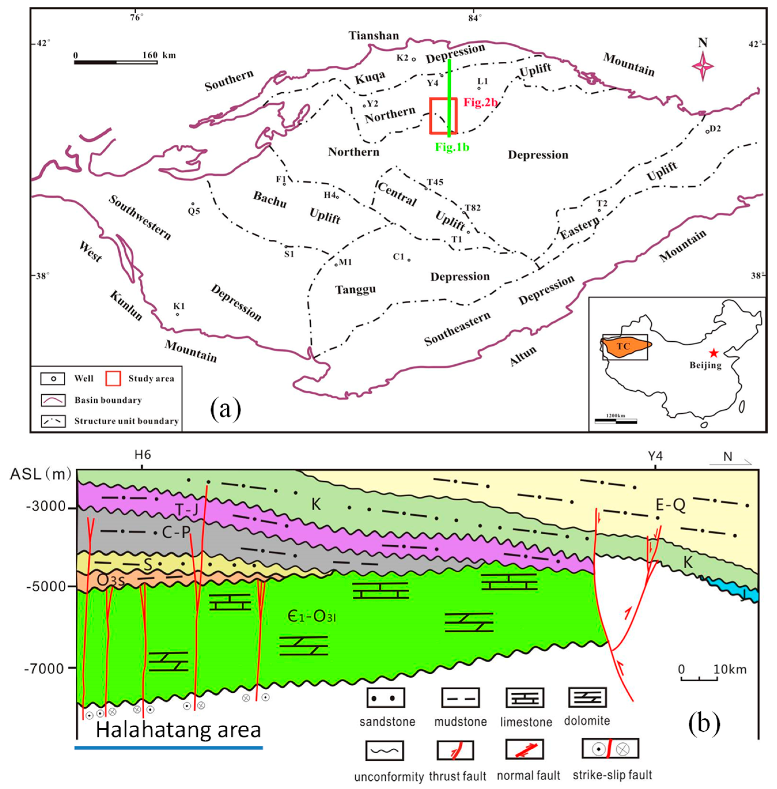
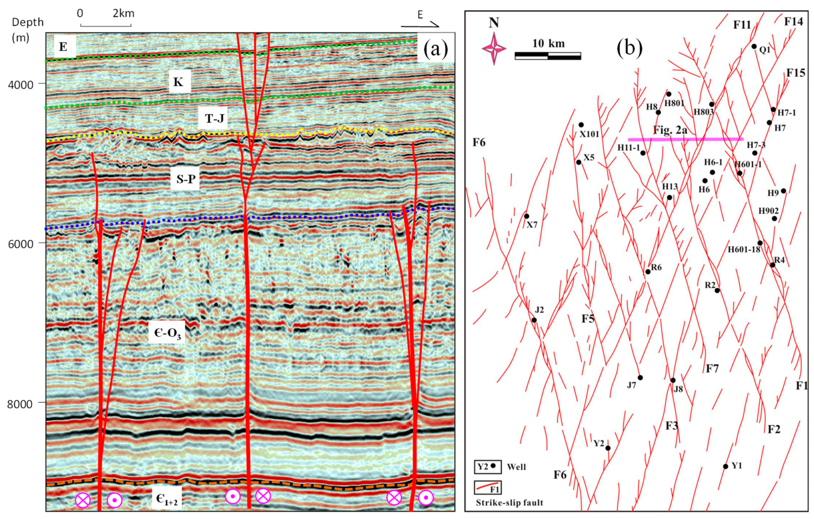
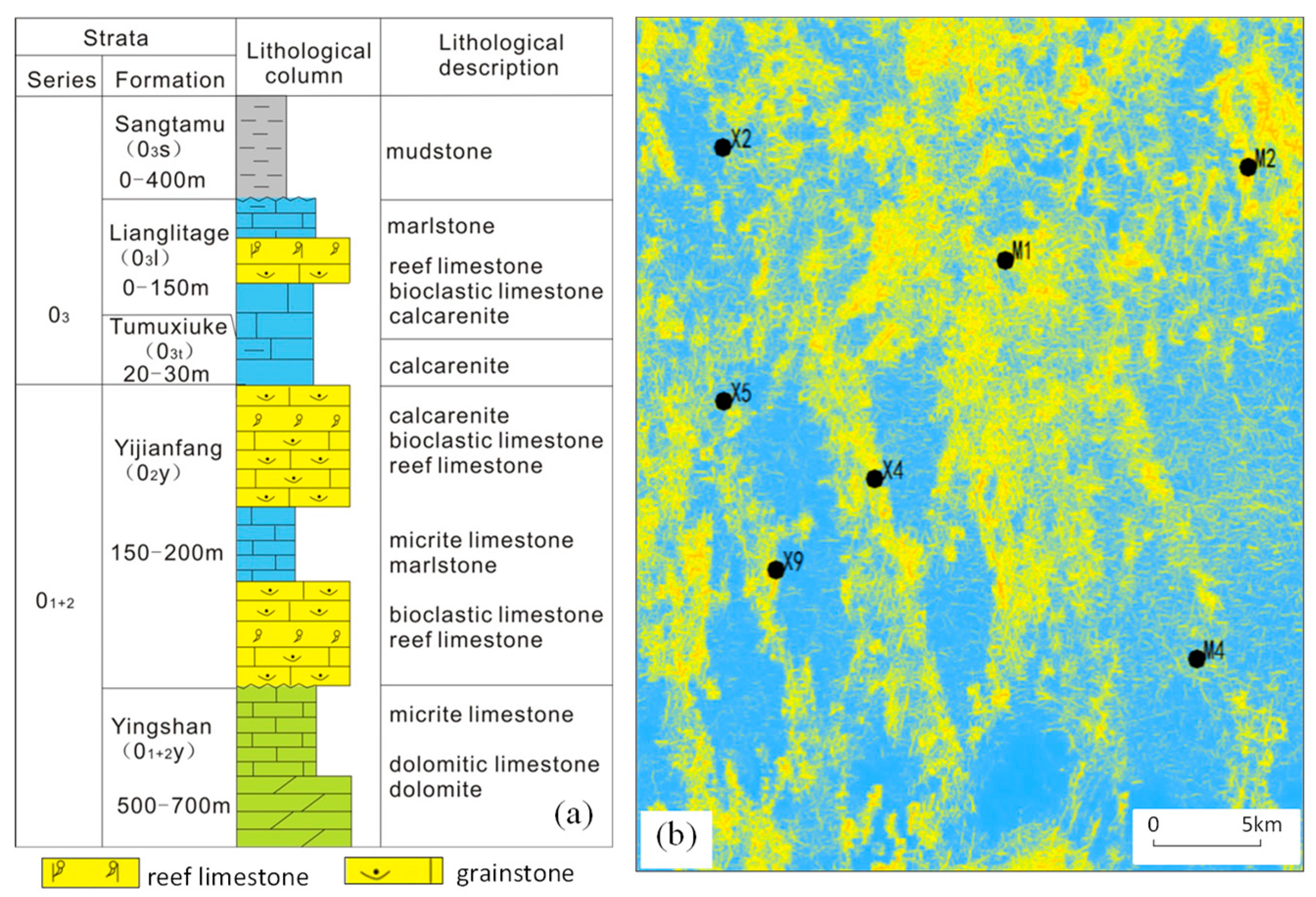
2. Geological Setting
3. Data and Methods
4. Structure Related Diagenesis
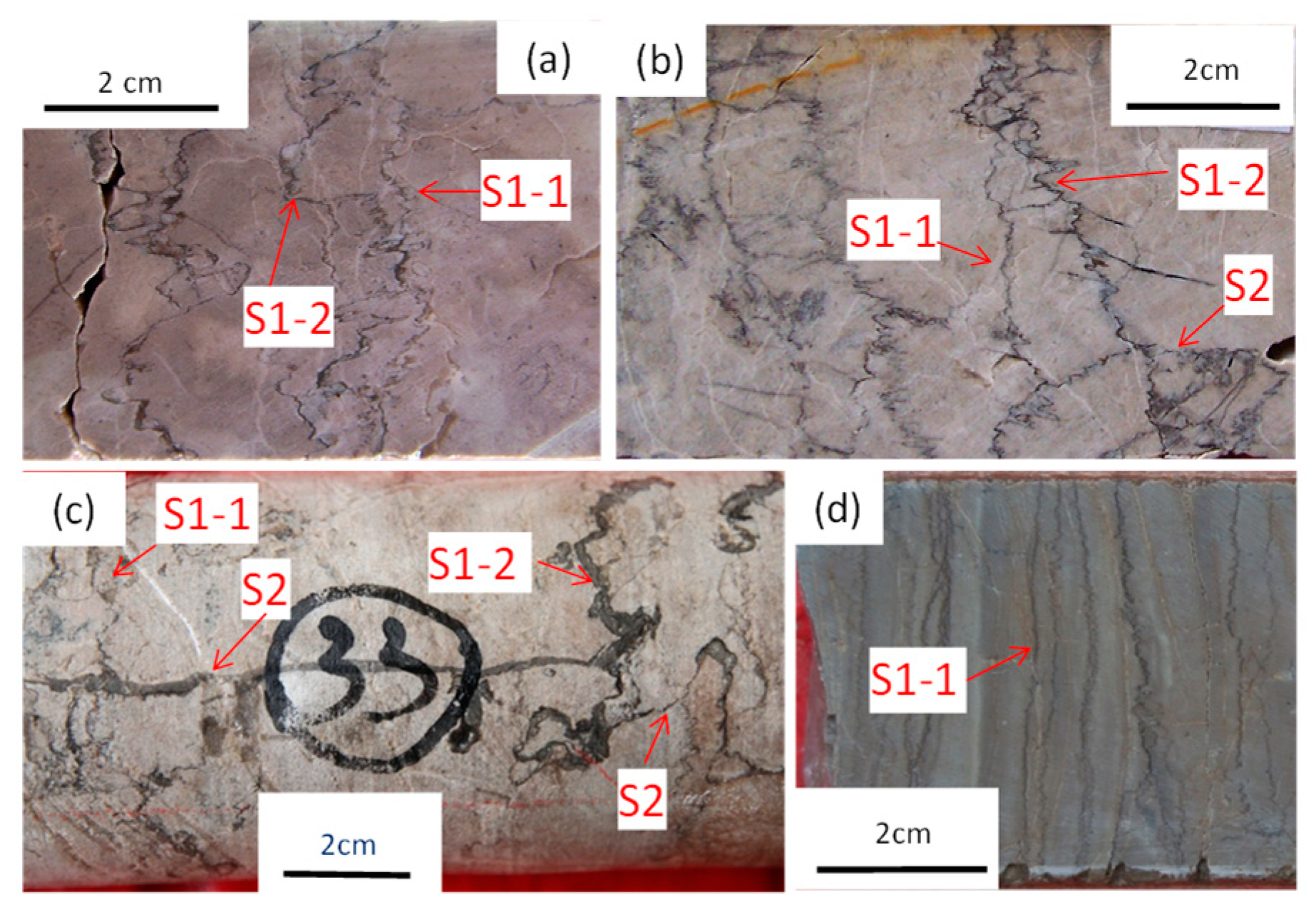
4.1. Compaction and Pressure Solution
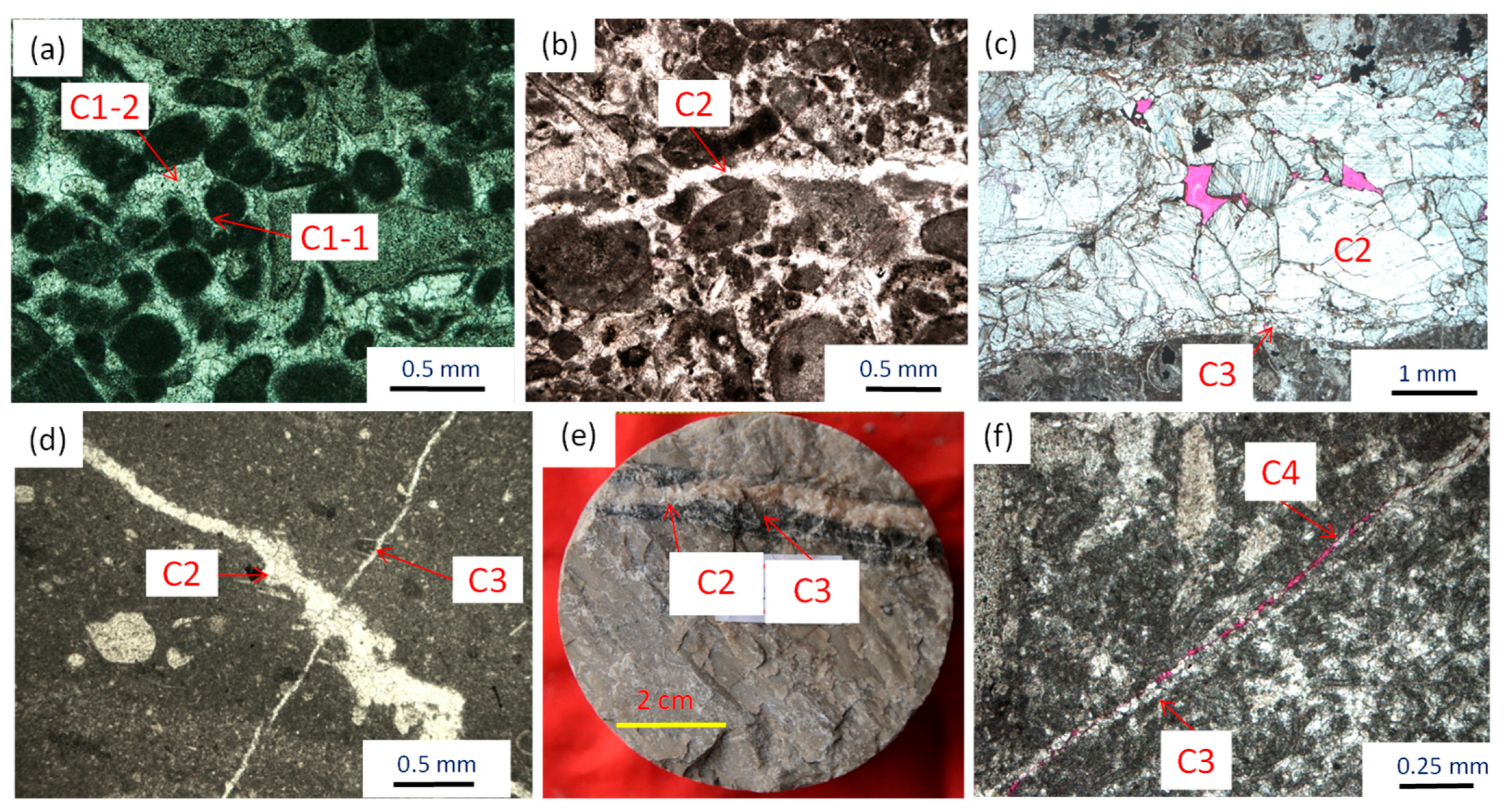
4.2. Cementation
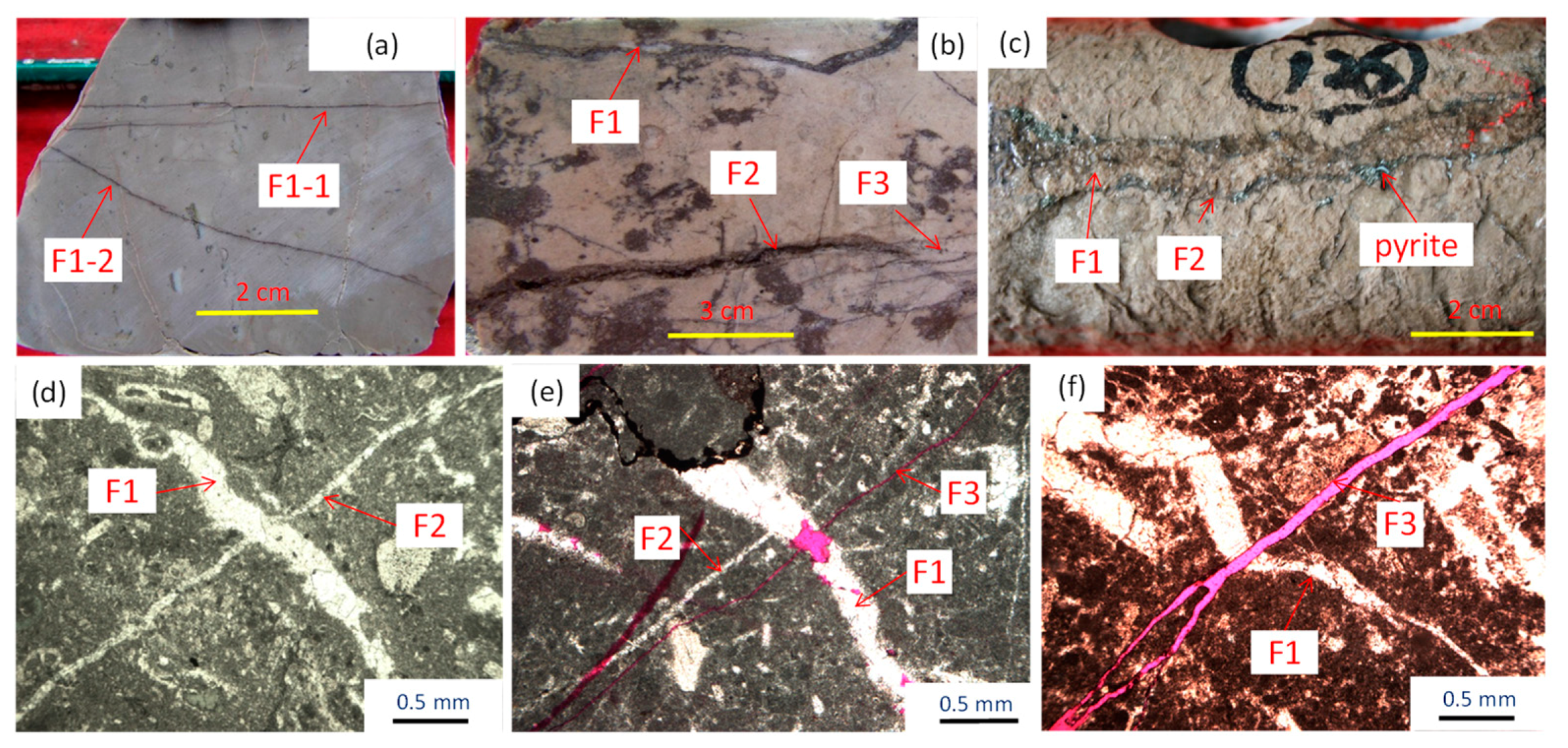
4.3. Fracturing
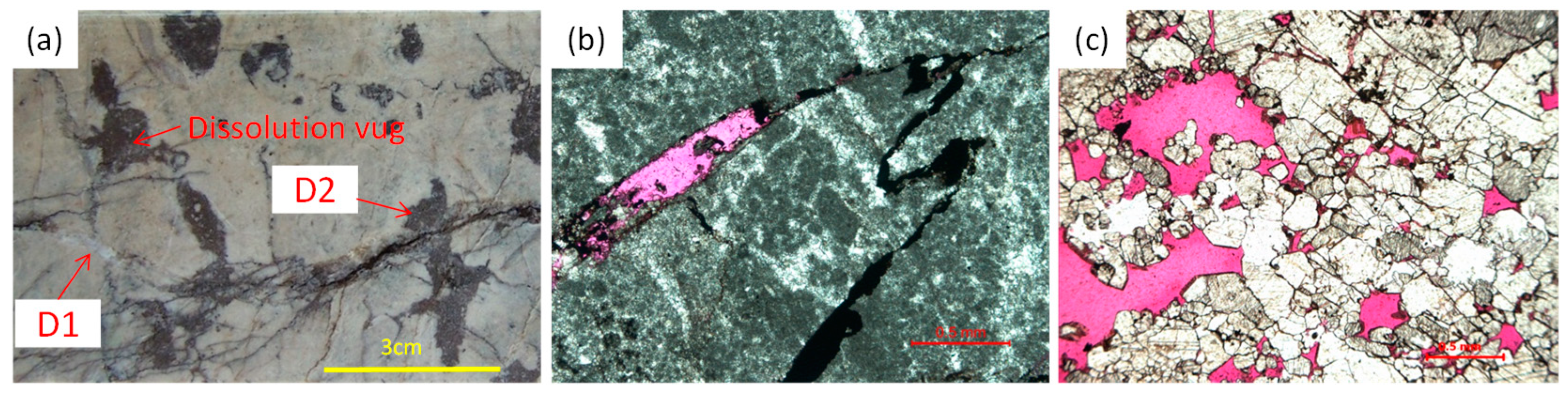
4.4. Dissolution
5. Discussion
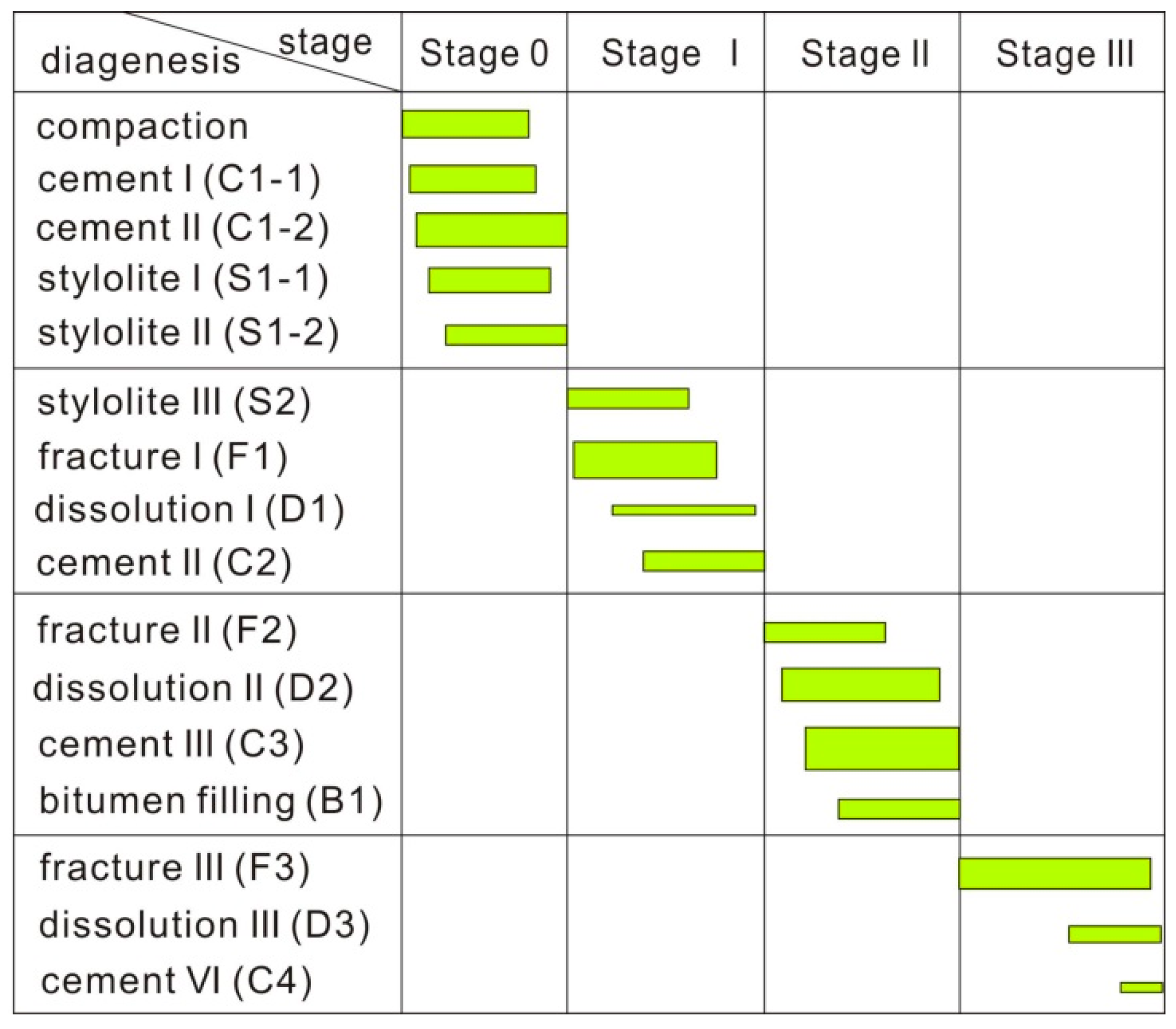
5.1. Paragenetic Sequence of the Structure Related Diagenesis
5.2. Fault Controls on the Structural Diagenesis
6. Conclusions
- Multiple phases of carbonate diagenesis in the fault damage zones may be identified from the subsurface based upon stylolite type and fracture cross-cutting relationships, fracture orientations and cementation generations in the sedimentary basin strata.
- The country rocks have undergone strong compaction, pressure solution and cementation, during deep burial, but few fracture and dissolution porosity features are evident in the Ordovician carbonates in this study area. However, there are complicated compaction, 1-2 stages of tectonic stylolites, 2-4 stages fractures and associated cementation and dissolution in these same carbonates found along the fault damage zones.
- In contrast to the country rocks, this study suggests an additional three cycles of structural diagenesis occurred within the carbonate fault damage zones. The two early stages of fracture activities are followed by strong cementation, while much more open fracture is characteristic of the latest stage of brittle deformation.
- The carbonate structure related diagenesis is constrained to the fault zones, and its spatio-temporal distribution and variation are mainly controlled by the three different stages of fault activities affecting these rocks.
Author Contributions
Funding
Acknowledgments
Conflicts of Interest
References
- Faulkner, D.R.; Jackson, C.A.L.; Lunn, R.J.; Schlische, R.W.; Shipton, Z.K.; Wibberley, C.A.J.; Withjack, M.O. A review of recent developments concerning the structure, mechanics and fluid flow properties of fault zones. J. Struct. Geol. 2010, 32, 1557–1575. [Google Scholar] [CrossRef]
- Bense, V.F.; Gleeson, T.; Loveless, S.E.; Bour, O.; Scibek, J. Fault zone hydrogeology. Earth Sci. Rev. 2013, 127, 171–192. [Google Scholar] [CrossRef]
- Trippetta, F.; Carpenter, B.M.; Mollo, S.; Scuderi, M.M.; Scarlato, P.; Collettini, C. Physical and transport property variations within carbonate-bearing fault zones: Insights from the Monte Maggio Fault (Central Italy). Geochem. Geophys. Geosyst. 2017, 18, 4027–4042. [Google Scholar] [CrossRef]
- Caine, S.J.; Evans, J.P.; Forster, C.B. Fault zone architecture and permeability structure. Geology 1996, 24, 1025–1028. [Google Scholar] [CrossRef]
- Kim, Y.S.; Peacock, D.C.P.; Sanderson, D.J. Fault damage zones. J. Struct. Geol. 2004, 26, 503–517. [Google Scholar] [CrossRef]
- Peacock, D.C.P.; Dimmen, V.; Rotevatn, A.; Sanderson, D.J. A broader classification of damage zones. J. Struct. Geol. 2017, 102, 179–192. [Google Scholar] [CrossRef]
- Moore, C.H. Carbonate Diagenesis and Porosity. In Developments in Sedimentology; Elsevier Science Publishers: Amsterdam, The Netherlands, 1989. [Google Scholar]
- Wilson, J.E.; Goodwin, L.B.; Lewis, C. Diagenesis of deformation band faults: Record and mechanical consequences of vadose zone flow and transport in the Bandelier Tuff, Los Alamos, New Mexico. J. Geophys. Res. 2006, 111, B09201. [Google Scholar] [CrossRef]
- Laubach, S.E.; Eichhubl, P.; Hilgers, C.; Lander, R.H. Structural diagenesis. J. Struct. Geol. 2010, 32, 1866–1872. [Google Scholar] [CrossRef]
- Laubach, S.E.; Ward, M.W. Diagenesis in porosity evolution of opening-mode fractures, Middle Triassic to Lower Jurassic La Boca Formation, NE Mexico. Tectonophysics 2006, 419, 75–97. [Google Scholar] [CrossRef]
- Olson, J.E.; Laubach, S.E.; Lander, R.H. Natural fracture characterization in tight gas sandstones: Integrating mechanics and diagenesis. AAPG Bull. 2009, 93, 1535–1549. [Google Scholar] [CrossRef]
- Rath, A.; Exner, U.; Tschegg, C.; Grasemann, B. Diagenetic control of deformation mechanisms in deformation bands in a carbonate grainstone. AAPG Bull. 2011, 95, 1369–1381. [Google Scholar] [CrossRef]
- Hooker, J.N.; Gomez, L.A.; Laubach, S.E.; Gale, J.F.W.; Marrett, R. Effects of diagenesis (cement precipitation) during fracture opening on fracture aperture-size scaling in carbonate rocks. Geol. Soc. Lond. Spec. Publ. 2012, 370, 187–206. [Google Scholar] [CrossRef]
- Hodson, K.R.; Crider, J.G.; Huntington, K.W. Temperature and composition of carbonate cements record early structural control on cementation in a nascent deformation band fault zone: Moab Fault, Utah, USA. Tectonophysics 2016, 690, 240–252. [Google Scholar] [CrossRef]
- Williams, R.T.; Goodwin, L.B.; Mozley, P.S. Diagenetic controls on the evolution of fault-zone architecture and permeability structure: Implications for episodicity of fault-zone fluid transport in extensional basins. GSA Bull. 2017, 129, 464–478. [Google Scholar] [CrossRef]
- Knipe, R.J. The influence of fault zone processes and diagenesis on fluid flow. In Diagenesis and Basin Development (AAPG Studies in Geology); Horbury, A.D., Robinson, A.G., Eds.; American Association of Petroleum Geologists: Tulsa, OK, USA, 1993; pp. 135–154. [Google Scholar]
- Eichhubl, P.; Davatzes, N.C.; Becker, S.P. Structural and diagenetic control of fluid migration and cementation along the Moab fault, Utah. AAPG Bull. 2009, 93, 653–681. [Google Scholar] [CrossRef] [Green Version]
- Yielding, G.; Bretan, P.; Freeman, B. Fault seal calibration: A brief review. Geol. Soc. Lond. Spec. Publ. 2010, 347, 243–255. [Google Scholar] [CrossRef]
- Vandeginste, V.; Swennen, R.; Allaeys, M.; Ellam, R.M.; Osadetz, K.; Roure, F. Challenges of structural diagenesis in foreland fold-and-thrust belts: A case study on paleofluid flow in the Canadian Rocky Mountains West of Calgary. Mar. Pet. Geol. 2012, 35, 235–251. [Google Scholar] [CrossRef] [Green Version]
- Pei, Y.; Paton, D.A.; Knipe, R.J.; Wu, K. A review of fault sealing behaviour and its evaluation in siliciclastic rocks. Earth Sci. Rev. 2015, 150, 121–138. [Google Scholar] [CrossRef]
- De Graaf, S.; Reijmer, J.J.G.; Bertotti, G.V.; Bezerra, F.H.R.; Cazarin, C.L.; Bisdom, K.; Vonhof, H.B. Fracturing and calcite cementation controlling fluid flow in the shallow-water carbonates of the Jandaíra Formation, Brazil. Mar. Pet. Geol. 2017, 80, 382–393. [Google Scholar] [CrossRef]
- Petrie, E.S.; Petrie, R.A.; Evans, J.P. Identification of reactivation and increased permeability associated with a fault damage zone using a multidisciplinary approach. J. Struct. Geol. 2014, 59, 37–49. [Google Scholar] [CrossRef]
- Eichhubl, P.; Boles, J.R. Rates of fluid flow in fault systems - evidence for episodic rapid fluid flow in the Miocene Monterey Formation, coastal California. Am. J. Sci. 2000, 300, 571–600. [Google Scholar] [CrossRef]
- Gratier, J.-P. Fault permeability and strength evolution related to fracturing and healing episodic processes (years to millennia): The role of pressure solution. Oil Gas Sci. Technol. 2011, 66, 491–506. [Google Scholar] [CrossRef]
- Jia, C.Z. Tectonic Characteristics and Petroleum, Tarim Basin, China; Geological Publishing House: Beijing, China, 1997; pp. 29–261. (In Chinese) [Google Scholar]
- Li, Q.M.; Wu, G.H.; Pang, X.Q.; Pan, W.Q.; Luo, C.S.; Wang, C.L.; Li, X.S.; Zhou, B. Hydrocarbon accumulation conditions of Ordovician carbonate in Tarim Basin. Acta Geol. Sin. 2010, 84, 1180–1194. [Google Scholar]
- Tang, L.J.; Huang, T.Z.; Qiu, H.J.; Wan, G.M.; Li, M.; Yang, Y.; Xie, D.Q.; Chen, G. Fault systems and their mechanisms of the formation and distribution of the Tarim Basin, NW China. J. Earth Sci. 2014, 25, 169–182. [Google Scholar] [CrossRef]
- Du, J.H. Oil and Gas Exploration of Cambrian-Ordovician Carbonate in Tarim Basin; Petroleum Industry Press: Beijing, China, 2010. (In Chinese) [Google Scholar]
- Wu, G.H.; Yuan, Y.J.; Huang, S.Y.; Vandyk, T.M.; Xiao, Y.; Cai, Q.; Luo, B.X. The dihedral angle and intersection processes of a conjugate strike-slip fault system in the Tarim Basin, NW China. Acta Geol. Sin. Engl. Ed. 2018, 92, 74–88. [Google Scholar] [CrossRef]
- Wu, G.H.; Gao, L.H.; Zhang, Y.T.; Ning, C.Z.; Xie, E. Fracture attributes in reservoir-scale carbonate fault damage zones and implications for damage zone width and growth in the deep subsurface. J. Struct. Geol. 2019, 118, 181–193. [Google Scholar] [CrossRef]
- Wan, X.G.; Wu, G.H.; Yang, P.F.; Gao, L.H. The seismic technique description of carbonate fault damage zone in Halahatang area, Tarim basin. Oil Gas Geol. 2016, 37, 785–791, (In Chinese with English abstract). [Google Scholar]
- Gao, Z.Q.; Fan, T.L. Carbonate platform-margin architecture and its influence on Cambrian-Ordovician reef-shoal development, Tarim Basin, NW China. Mar. Pet. Geol. 2015, 68, 291–306. [Google Scholar] [CrossRef]
- Zhao, K.Z.; Zhang, L.J.; Zheng, D.M.; Sun, C.H.; Dang, Q.N. A reserve calculation method for fracture-cavity carbonate reservoirs in Tarim Basin, NW China. Pet. Explor. Dev. 2015, 42, 277–282. [Google Scholar] [CrossRef]
- Ni, X.F.; Shen, A.J.; Pan, W.Q.; Zhang, R.H.; Yu, H.F.; Dong, Y.; Zhu, Y.F.; Wang, C.F. Geological modeling of excellent fracture-vug carbonate reservoirs: A case study of the Ordovician in the northern slope of Tazhong palaeo-uplift and the southern area of Tabei slope, Tarim Basin, NW China. Pet. Explor. Dev. 2013, 40, 444–453. [Google Scholar] [CrossRef]
- Viniegra, F.; Castillo-Tejero, C. Golden Lane fields, Veracruz, Mexico, in Geology of giant petroleum fields. AAPG Mem. 1970, 14, 309–325. [Google Scholar]
- Howard, J.P.; Bogolepova, O.K.; Gubanov, A.P.; Gόmez-Pérez, M. The petroleum potential of the Riphean–Vendian succession of southern East Siberia. Geol. Soc. Lond. Spec. Publ. 2012, 366, 177–198. [Google Scholar] [CrossRef]
- Palmer, A.N. Origin and morphology of limestone caves. Geol. Soc. Am. Bull. 1991, 103, 1–21. [Google Scholar] [CrossRef]
- Davies, G.R.; Smith, L.B. Structurally controlled hydrothermal dolomite reservoir facies: An overview. AAPG Bull. 2006, 90, 1641–1690. [Google Scholar] [CrossRef]
- Cazarin, C.L.; Bezerra, F.H.R.; Borghic, L.; Santosd, R.V.; Favoretoc, J.; Brode, J.A.; Aulerf, A.S.; Srivastavab, N.K. The conduit-seal system of hypogene karst in Neoproterozoic carbonates in northeastern Brazil. Mar. Pet. Geol. 2019, 101, 90–107. [Google Scholar] [CrossRef]
- Zhang, H.; Cai, Z.X.; Qi, L.X.; Yun, L. Diagenesis and origin of porosity formation of Upper Ordovician carbonate reservoir in northwestern Tazhong condensate field. J. Nat. Gas Sci. Eng. 2017, 38, 139–158. [Google Scholar] [CrossRef]
- Croizé, D.; Renard, F.; Gratier, J.-P. Compaction and porosity reduction in carbonates: A review of observations, theory and experiments. Adv. Geophys. 2013, 54, 181–238. [Google Scholar]
- Baud, P.; Rolland, A.; Heap, M.; Xu, T.; Nicolé, M.; Ferrand, T.; Reuschlé, T.; Toussaint, R.; Conil, N. Impact of stylolites on the mechanical strength of limestone. Tectonophysics 2016, 690, 4–20. [Google Scholar] [CrossRef] [Green Version]
- Toussaint, R.; Aharonov, E.; Koehn, D.; Gratier, J.P.; Ebner, M.; Baud, P.; Rolland, A.; Renard, F. Stylolites: A review. J. Struct. Geol. 2018, 114, 163–195. [Google Scholar] [CrossRef] [Green Version]
- Laubach, S.E.; Eichhubl, P.; Hargrove, P.; Ellis, M.A.; Hooker, J.N. Fault core and damage zone fracture attributes vary along strike owing to interaction of fracture growth, quartz accumulation, and differing sandstone composition. J. Struct. Geol. 2014, 68, 207–226. [Google Scholar] [CrossRef] [Green Version]
- Pollard, D.D.; Aydin, A. Progress in understanding jointing over the past century. Geol. Soc. Am. Bull. 1998, 100, 1181–1204. [Google Scholar] [CrossRef]
- Becker, S.P.; Eichhubl, P.; Laubach, S.E.; Reed, R.M.; Lander, R.H.; Bodnar, R.J. A 48 m.y. history of fracture opening, temperature, and fluid pressure: Cretaceous Travis Peak Formation, East Texas Basin. GSA Bull. 2010, 122, 1081–1093. [Google Scholar] [CrossRef]
- Choquette, P.W.; Pray, L.C. Geologic nomenclature and classification of porosity in sedimentary carbonates. AAPG Bull. 1970, 54, 207–250. [Google Scholar]
- Jia, L.Q.; Cai, C.F.; Jiang, L.; Zhang, K.; Li, H.X.; Zhang, W. Petrological and geochemical constraints on diagenesis and deep burial dissolution of the Ordovician carbonate reservoirs in the Tazhong area, Tarim Basin, NW China. Mar. Pet. Geol. 2016, 78, 271–290. [Google Scholar] [CrossRef]
- Liu, W.; Huang, Q.Y.; Wang, K.; Shi, S.Y.; Jiang, H. Characteristics of hydrothermal activity in the Tarim Basin and its reworking effect on carbonate reservoirs. Nat. Gas Ind. B 2016, 3, 202–208. [Google Scholar] [CrossRef]
- Wang, Z.Y.; Wu, L.; Zhang, Y.F.; Han, J.F.; Zhang, L.J. Study on category and forming environment of Upper Ordovician carbonate rock calcite cement in Tazhong district. J. Earth Sci. Environ. 2009, 31, 265–271, (In Chinese with English abstract). [Google Scholar]
- Wu, G.H.; Yang, H.J.; He, S.; Cao, S.J.; Liu, X.; Jing, B. Effects of structural segmentation and faulting on carbonate reservoir properties: A case study from the Central Uplift of the Tarim Basin, China. Mar. Petrol. Geol. 2016, 71, 183–197. [Google Scholar] [CrossRef]
- Weedman, S.D.; Brantley, S.L.; Shiraki, R.; Poulson, S.R. Diagenesis, compaction, and fluid chemistry modeling of a sandstone near a pressure seal: Lower Tuscaloosa Formation, Gulf Coast. AAPG Bull. 1996, 80, 1045–1064. [Google Scholar]
- Franks, S.G.; Forester, R.W. Relationships among Secondary Porosity, Pore-Fluid Chemistry and Carbon Dioxide, Texas Gulf Coast. AAPG Bull. Mem. 1984, 37, 63–79. [Google Scholar]


| Diagenesis | Country Rocks | Damage Zone |
|---|---|---|
| Compaction | relatively strong, line/serrate contacts | multiple point/line/serrate contacts |
| Pressure solution | 1-2 stages, serrate and wave-like profiles, bedding-parallel stylolites; tight | 2-3 stages, bedding-parallel and inclined stylolites and 1-2 stages tectonic stylolites, localized dissolution porosity and bitumen infill |
| Fracturing | undeveloped, one set of regional sub-vertical fracture, calcite infill/cementation, little dissolution of porosity | 2-4 stages, multiple kinds and orientations of fractures, partial filling/cement, multiple-stages of dissolution enhancing porosity |
| Cementation | 1-2 stages of marine cements, 1-2 stages eogenetic-mesogenetic cements, strong cementation and little dissolution | 2-5 stages eogenetic-mesogenetic cements, relatively weak cementation and multiple-stages of dissolution |
| Dissolution | a few burial dissolution, dissolution porosity occluded by cements | 2-4 stages dissolution, development of partially filled porosity, vugs and caves |
© 2019 by the authors. Licensee MDPI, Basel, Switzerland. This article is an open access article distributed under the terms and conditions of the Creative Commons Attribution (CC BY) license (http://creativecommons.org/licenses/by/4.0/).
Share and Cite
Wu, G.; Xie, E.; Zhang, Y.; Qing, H.; Luo, X.; Sun, C. Structural Diagenesis in Carbonate Rocks as Identified in Fault Damage Zones in the Northern Tarim Basin, NW China. Minerals 2019, 9, 360. https://doi.org/10.3390/min9060360
Wu G, Xie E, Zhang Y, Qing H, Luo X, Sun C. Structural Diagenesis in Carbonate Rocks as Identified in Fault Damage Zones in the Northern Tarim Basin, NW China. Minerals. 2019; 9(6):360. https://doi.org/10.3390/min9060360
Chicago/Turabian StyleWu, Guanghui, En Xie, Yunfeng Zhang, Hairuo Qing, Xinsheng Luo, and Chong Sun. 2019. "Structural Diagenesis in Carbonate Rocks as Identified in Fault Damage Zones in the Northern Tarim Basin, NW China" Minerals 9, no. 6: 360. https://doi.org/10.3390/min9060360