1. Introduction
Bentonite is a type of clay composed primarily of montmorillonite, which is a phyllosilicate mineral with a layered structure and belongs to the smectite group [
1]. Montmorillonite has a layered structure, which confers interesting properties such as a swelling ability, a high cation exchange capacity (CEC), and low hydraulic conductivity. Additionally, montmorillonite exhibits high chemical stability, which is an important barrier property in terms of interaction with other barrier materials [
2,
3]. These properties make bentonite an excellent material to use as a buffer or backfill material in deep geological repositories (DGRs) for radioactive waste [
4,
5,
6,
7].
The MX-80 and FEBEX bentonites contain 3–4 wt.% of total Fe, included in accessory minerals but primarily as structural iron in montmorillonite, most of it as Fe
III (
80% in MX-80) and the remainder as Fe
II. The redox properties of iron can affect the properties of the bentonite barrier. For example, under reducing conditions, Fe(III) can be reduced into Fe(II), increasing the layer charge, which can result in a decrease in the swelling capacity [
8]. Redox transitions can also affect the hydraulic conductivity and layer charge of the clay. A reduction of Fe(III) into Fe(II) in the dioctahedral layer increases the layer charge, which promotes an increase in the CEC too [
9,
10,
11].
Depending on a country’s nuclear waste policy, high-level waste (HLW) can be isolated using copper, carbon steel, or different alloys [
12,
13,
14]. The corrosion rate depends on the metallic composition of the canister, as well as other factors, such as the bentonite and the geological conditions in the host rock [
15]. The corrosion mechanisms of carbon steel in a deep geological repository of radioactive waste involve several complex processes. The repository environment is characterized by high temperatures, elevated pressure, and the presence of various aqueous chemical species, including dissolved oxygen and highly reactive ions, such as chlorides or sulphates under oxic conditions [
7]. These conditions can lead to the initiation and propagation of corrosion, and this could compromise the integrity of the metallic waste container and release radioactive materials into the near field [
7,
10].
The initial stage of corrosion involves the formation of an oxide layer on the steel surface. This layer can provide some protection against further corrosion, preventing the diffusion of oxygen and other species into the underlying steel. Under anaerobic conditions, the oxide layer can be modified, and corrosion may occur according to an electrochemical process involving the transfer of electrons from the steel surface to dissolved oxygen, generating H
2 or other oxidants in the surrounding environment, leading to the formation of corrosion products such as iron oxides and hydroxides [
16].
The presence of chlorides or sulphates can accelerate the corrosion processes under oxic conditions by increasing the rate of electron transfer and promoting the dissolution of the protective oxide layer. Additionally, the high temperatures and pressure in the repository environment can enhance the mobility of the aqueous species and the diffusion of the corrosion products. Under these conditions, the iron in the bentonite can interact with the surrounding environment, leading to the formation of various iron minerals, including magnetite (Fe
3O
4). In addition to magnetite, other iron minerals may also form or be present in the bentonite, including hematite (Fe
2O
3) and goethite (FeO(OH)) [
17,
18]. These minerals can interact either via dissolution and reaction (dissolved Fe adsorption) [
19,
20] or bridging the octahedral sheet extremes of the montmorillonite in the bentonite, affecting properties such as its swelling capacity, layer charge, or cation fixation [
11], and potentially altering its ability to act as a barrier [
21,
22].
Two types of experiments have been traditionally used to study iron–bentonite interactions: in situ experiments, which are conducted under realistic disposal conditions in underground galleries, and laboratory experiments, which enable controlled experiments under a wider range of experimental conditions, including elevated temperature and hydration [
23,
24,
25,
26,
27]. A long-term in situ corrosion experiment was conducted in Opalinus Clay at the Mont Terri Underground Research Laboratory (Switzerland), where carbon steel coupons were embedded into MX-80 bentonite. The samples showed the development of a reddish–brown corrosion front or halo around the corroding metal interface. This was attributed to an increase in Fe (II/III) in the bentonite matrix. SEM/EDX measurements confirmed the presence of iron in the halos. These halos were the products of aerobic corrosion at the first stage with oxygen available, rather than the green or black corrosion products formed during the anaerobic corrosion of iron, due to oxygen consumption [
25]. Similar phenomena have been reported in a similar corrosion experiment conducted in crystalline rock [
15].
In addition to the in situ corrosion experiments described above, several laboratory-based experimental studies have been conducted in the past with the objective of characterizing the changes in the chemical composition and microstructure of the bentonite in close proximity to corroding carbon steel [
28,
29,
30]. The analysis of the steel–bentonite interface revealed that microfractures in the bentonite occurred close to the corroding surfaces, which were enriched in iron. The corrosion product layer at the surface of the carbon steel was predominantly composed of sub-stoichiometric magnetite or a mixed-phase spinel (e.g., Fe
3-xM
xO
4) with the possible presence of carbonate minerals. This complex microstructure of the corrosion product layer has been observed in both in situ and laboratory experiments.
The smectite particles close to the metallic corroding surface may also be enriched in Fe due to the Fe–bentonite interaction [
28,
31]. The metallic corrosion layer composition can be modified by corrosion products due to the incorporation of chemical species such as carbonates, silicates, and sulfides, as a result of the dissolution of the primary bentonite minerals. This could potentially drive further mineral transformations [
7].
The corrosion of steel in contact with bentonite in in situ experiments is commonly understood to occur in two stages: first, an aerobic stage where Fe
3+ and corrosion products are generated on the steel surface, followed by an anaerobic stage, where Fe
2+ is generated after oxygen is depleted from the system. During the anaerobic phase, authors agree that Fe
2+ diffuses into the bentonite and interacts primarily through ion exchange [
25,
29,
32,
33]. Conversely, Fe
3+ was mainly found near the steel–bentonite interface, a few centimeters (<4.5 cm) inside the bentonite, in a long-term experiment that ran for nearly 20 years [
22]. The hindrance of Fe
2+ diffusion by the oxygen present in the bentonite was proposed as the mechanism for this phenomenon. Laboratory batch experiments performed with bentonite and native iron at 60 °C for 1 month showed that corrosion can occur anaerobically, even under laboratory conditions [
25]. As a result, Fe
2+ was oxidized into Fe
3+ and precipitated mainly as goethite, when it diffused into the aerobic zone of bentonite [
25,
29].
Wersin and Kober [
16,
27] proposed a corrosion mechanism for the iron–bentonite interaction comprising four stages: (0) Formation of a thin magnetite layer on carbon steel and prevailing structural Fe(III) in the smectite component at low moisture; (1) Fe(III) oxide formed, whether anhydrous, such as hematite and maghemite, or oxyhydroxides, such as goethite and lepidocrocite, depending on the bentonite moisture content; and (2) the thickness of the corrosion layer increases and the transfer of O
2 and H
2O into the steel decreases. Anaerobic corrosion arises within the corrosion layer, generating Fe(II) and resulting in the formation of magnetite and siderite in the bentonite interface. Additionally, there is rapid electron transfer across the corrosion layer, leading to Fe(II) generation at the interface of the corrosion layer/bentonite, which then reacts with the remaining O
2 to produce further Fe(III) oxides. From this stage onward (stage 3), anaerobic conditions are established, and the corrosion of the steel continues to create Fe(II) and magnetite/siderite with Fe(II), diffusing into the bentonite farther from the iron contact and amassing in the clay, controlled by sorption processes, followed by oxidation. The transfer process probably involves redox reactions with the structural Fe(III) and previously formed (and pre-existing) Fe(III) oxides near the interface, though the precise mechanism of this transfer process remains to be established [
16]. The accumulated Fe
3+ near the interface is slowly displaced toward the bentonite. Leupin et al. [
30] compiled several reaction paths justifying the anoxic corrosion model producing Fe(II) and Fe(III) oxides and hydrogen at the corrosion interface. Mobile iron species can interact with the bentonite and lead to the formation of iron-rich clay minerals and precipitates around the steel–bentonite interface. The dissolved Fe
2+ released at micro-molar concentrations due to the corrosion of steel canisters can interact with montmorillonite and change the mineral oxide reduction state, potentially affecting relevant mineral properties. Additionally, ferrous iron may compete with cationic radionuclides for the cation exchange capacity of the clay, which could result in a reduction in the sorption capacity of the bentonite [
31].
The solubility of reduced iron is controlled by solid phases like green rust, magnetite, or Fe(OH)
2 [
34]. The presence of Fe(II) could provide adsorption–desorption phenomena through exchange with other cations like Na, Ca, or Mg [
35]. This Fe(II) can be exchanged in the form of Fe
2+, as well as FeCl
+ [
34].
Despite the fact that long-term studies in underground laboratories performed for several years to decades have shown limited corrosion effects on the bentonite barrier, there is not a complete picture of the prevailing Fe II and III minerals controlling the evolution of mineralogical alterations in bentonite [
15,
24,
30]. Thus, further research is needed to better understand these interactions and their potential impact on the safety of nuclear waste disposal in clay environments [
36]. In order to enhance the mineralogical expression of the Fe(II) interaction environment and study the potential oxidation and mobility of iron aqueous species in simulated initial anaerobic conditions, in the present study, FeCl
2 powder has been placed in contact with bentonite, in substitution of steel, as previously used by Mota-Heredia et al. [
37].
2. Materials and Methods
2.1. Experimental Setup
The experiments were performed in a glove box with an inert atmosphere of N
2 in order to prevent the oxidation of the FeCl
2 powder before starting the experiments. FeCl
2 was introduced into the cell until a thickness of uncompressed powder of ~4 mm was achieved, measured using a vernier caliper. The amount of FeCl
2 inserted into the cell was calculated by the difference in the weight of the reagent container. Thereafter, bentonite powder was introduced on top of the FeCl
2 and compacted using a hydraulic press. Bentonite blocks were theoretically compacted to attain a dry density of 1.65 g·cm
−3, 21 mm in height, and 50 mm in diameter. Each portion of bentonite powder was weighed beforehand, with a mass of 76.9 g FEBEX bentonite and 72.9 g MX-80 bentonite. These amounts were determined by considering the natural moisture content of each bentonite sample stored in the laboratory, 12.5 wt.% for FEBEX and 7.2 wt.% for MX-80. The experiments were performed using hydrothermal cells designed in-house, previously used in Mota-Heredia et al. [
37]. A complete description of the experimental setup is provided in the reference therein. The cells contain a cylindrical Teflon carcass inserted within a steel ring that minimizes the deformation in case of bentonite swelling. The FeCl
2 powder was placed at the bottom of the cells and heated at a constant temperature of 100 °C using a steel plate. A thermal gradient was established in the bentonite column, which was 100 °C at the bottom and 40 °C at the hydration zone, the upper part of the cells, where a synthetic saline solution representative of a generic clayey formation was pressurized (approximately at 1.5 bar) toward the bentonite. The experiments were carried out in a glove box, under a N
2 atmosphere, to prevent any contact with atmospheric O
2 during the experiment in case of failure and during the dismantling of the cells.
Although bentonite powder was inserted into the cells under a N2 atmosphere in the glove box, aerobic conditions due to the trapped air within the bentonite aggregates under the stock conditions were assumed to prevail. This, along with the oxic conditions of the saline solution, which was not degassed, leaded to initial aerobic conditions within the cells, mimicking the conditions that would occur in a repository during the operational phase when the engineered barriers are installed.
2.2. Materials
To maintain the hydration in the bentonite, a Na-Cl-SO
4-type synthetic saline solution was used, as described in Mota-Heredia et al. [
37]. The main chemical composition of the solution is: Cl
− = 38.9 mM, SO
42− = 13.8 mM, HCO
3− = 3.3 mM, Na
+ = 44.8 mM, K
+ = 1.8 mM, Ca
2+ = 7.5 mM, Mg
2+ = 5.1 mM, and pH 7.9.
Two types of bentonites were used: MX-80 and FEBEX. MX-80 is a type of Na-bentonite from Wyoming (USA), is considered a standard buffer and backfill material for radioactive waste disposal in various countries, and has been extensively studied in this field [
38,
39,
40,
41]. It is composed of
87 wt.% montmorillonite and includes accessory minerals such as quartz, feldspars, pyrite, and gypsum. Fe minerals like magnetite and goethite are present in traces.
FEBEX bentonite is extracted from the Cortijo de Archidona, at the Serrata de Níjar, Almería, Spain [
42,
43], and is considered the standard buffer material for radioactive waste disposal in Spain [
44]. This bentonite contains
85 wt.% of montmorillonite and accessory minerals such as quartz, cristobalite, calcite, and feldspars. It also contains traces of Fe minerals like magnetite and goethite. Various quantification studies have revealed a relative 10 wt.% error in the smectite content [
42,
45].
The anhydrous ferrous chloride used in this study was from Acros OrganicsTM (CAS 7758-94-3) and has 97% purity. It is presented in powder form and its solubility in water is 644 g·L−1. The amount of FeCl2 used for the MX-80 cell was 8.7 g, and 7.9 g was used for the FEBEX cell.
2.3. Sample Segmentation
At the end of the 6-month experimental time, FeCl
2–bentonite columns were taken apart from the Teflon cells, under a N
2 atmosphere, and hardened in epoxy resin for further sectioning. The cells were cut using a Struers™ Secotom-6 saw (Champigny sur Marne, France), while employing a cooling oil that neither interacts with the samples nor exposes them to atmospheric oxygen. Longitudinal cuts on the cylindrical bentonite samples were made using the Secotom-6 saw, while a cutter was used for transversal cuts. To analyze the reactivity along the hydrothermal gradient, the samples were cut to ensure that enough material was available for each characterization technique, as per the sampling method used in Mota-Heredia et al. [
37].
2.4. Analytical Methods
To measure the water content, the sample was heated to a constant weight at 105 °C, and the mass difference was calculated. The specific surface area (SSA) was determined according to the nitrogen adsorption using a Gemini V analyzer (Waltham, MA, USA) from Micrometrics and calculated using the BET method. The samples were ground and dried at 90 °C for 24 hours. Subsequently, the samples were degassed at 90 °C for at least an hour using a nitrogen gas stream and analyzed using the 5-point isotherm method [
46].
The CEC was determined using the Cu-trien method [
47], with the modifications made for clays as in Ammann [
48]. The absorbance was measured at 577 nm using a GENESYS 150 UV-visible spectrophotometer from Thermo Scientific (Waltham, MA, USA).
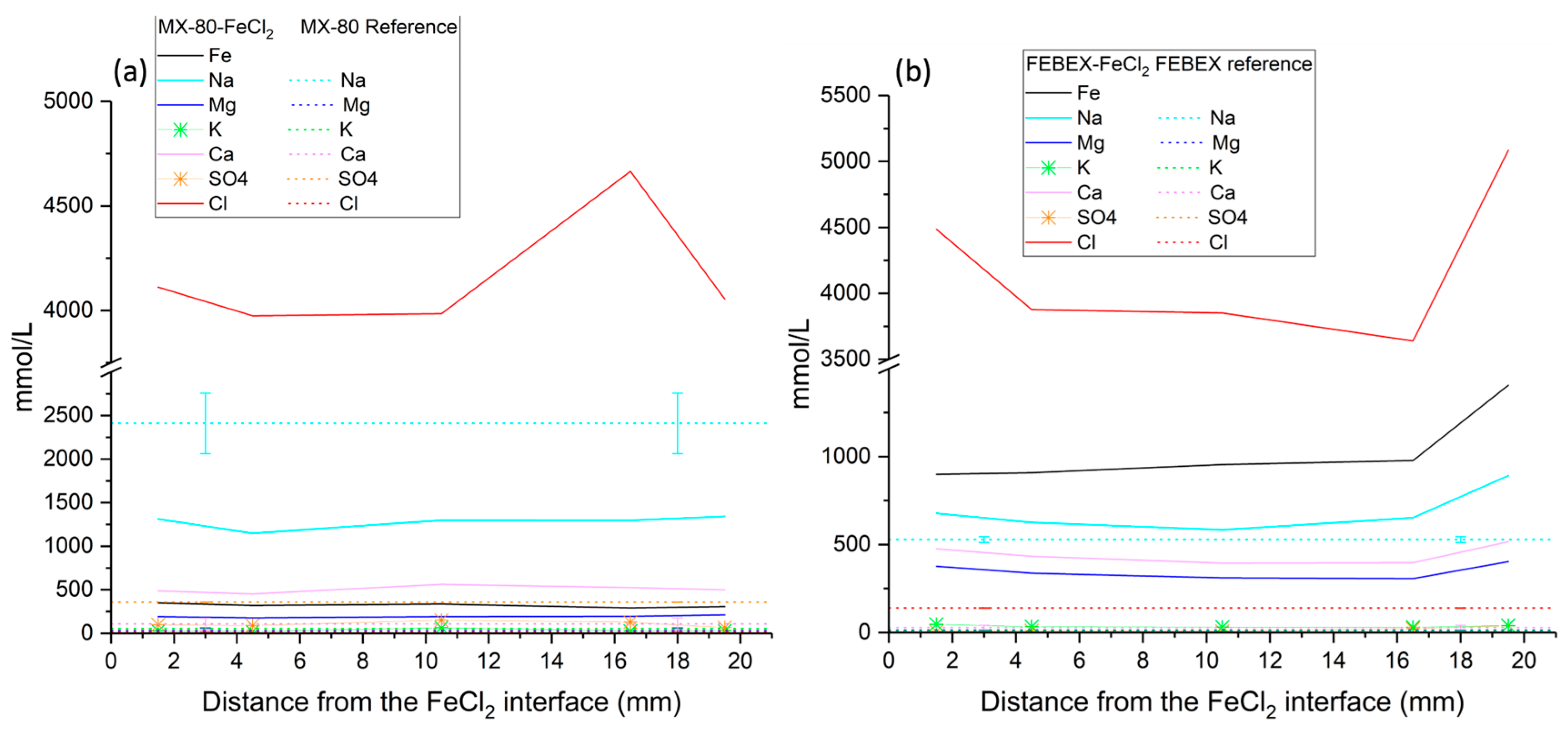
A 0.15 solid:liquid ratio was used to mix the samples with deionized water to obtain the aqueous extracts. The samples were then subjected to 24 h of interaction with water in a shaker, followed by centrifugation for 20 minutes at 10,000 rpm. Finally, the aqueous extracts were filtered using a pore size <0.45 µm. A Metrohm 888™ titration device (Herisau, Switzerland) was used to determine the pH of the porewater. Analyses of major ions including Na+, K+, Ca2+, Mg2+, Cl−, and SO42− were performed using a Metrohm 802™ Compact IC (Herisau, Switzerland) plus using ion chromatography.
Longitudinal thin section samples were prepared for scanning electron microscope (SEM) and energy-dispersive X-ray (EDX) analyses. Each sample was freeze-dried using immersion in liquid nitrogen and using a vacuum. After that, the samples were embedded and polished [
37]. The samples were coated with Au using a Q150T-S Quorum sputter coater system. Surface and morphology images were captured using a Hitachi S-3000N SEM coupled with an EDX XFlash
® 6130 Bruker detector (Madrid, Spain) for semi-quantification analyses of the chemical composition. Internal standard quantitative analyses were used for the EDX quantification. The microscope operated under high vacuum conditions with an accelerating voltage of 20 keV, a lifetime of 40 s, a working distance of 15.0 to 18.5 mm, and a beam current of 300 mA.
A SEM-EDX study was conducted to determine the chemical composition in a longitudinal profile, from the heater to the hydration zone. Greater magnification was applied to the images at the hottest zone where FeCl2 was placed, while lower magnification was carried out at the central and hydration zones, where the chemical variations were expected to be less significant. Around 20 analyses were conducted over a thickness of 2 mm at the steel–bentonite interface, 15 analyses over a thickness of 3 mm at the hydration zone, and 40 analyses at the intermedium zone over a thickness of 16 mm, although the number of analyses and thickness may vary slightly from one sample to another. The EDX analyses were used to observe the migration of FeCl2 along the bentonite and the concentration changes in elements such as Mg, Ca, Na, K, Cl, S, and Fe. The data were processed by removing C and O concentrations from the analyses and recalculating the remaining weight percentages. The mineralogy of bentonites was also analyzed on fresh fractured samples to observe the morphologies of the reaction products. Small samples that either fell apart or were manually separated were used for this study. The error of quantitative EDX analyses was between 10% and 20% depending on the type of preparation of samples.
To compare the redox state of Fe along the bentonite blocks, 1,10-phenanthroline was used according to the photochemical method described by Stucki [
49,
50]. This method allowed discrimination between the ferrous and total iron in the mineral samples. The procedure consists of sampling 50–100 mg dry bentonite and placing it in a propylene tube with 1.8 M H
2SO
4 and 48% hydrofluoric acid, adding 1,10-phenanthroline monohydrate in 95% ethanol as a 10% (wt/wt) solution, and then leaving the tube in a boiling water bath for 30 minutes. This procedure was carried out under red light to avoid photochemical oxidation of the Fe
2+ into Fe
3+. At this step, the complexation of Fe with phenanthroline takes place. The sample is neutralized with a solution of 5% (wt/wt) boric acid in water and is diluted with distilled water. After cooling for 15 minutes, an aliquot (1 mL) of the sample solution is taken and transferred into an Erlenmeyer flask, adding 10 mL of distilled water and 1 mL of 10% sodium citrate dihydrate in water. A GENESYS 150 UV-Visible spectrophotometer from Thermo Scientific (Waltham, MA, USA) was used to measure the absorbance at 510 nm.
The Erlenmeyer flask was then stoppered with parafilm to prevent evaporation and left for 72 hours in the light to allow photochemical oxidation of the Fe-phenanthroline. The absorbance is measured again at 510 nm to obtain the total iron content. Fe
3+ is measured by the difference between the total Fe and Fe
2+. The calculations were made using the absorptivity obtained by Stucki [
49], after observing the same linearity of the phenanthroline absorption. The formula used was C = Abs·ε
−1·l
−1, where C was the concentration of Fe
2+ or Fe total in wt.%; Abs the absorbance of the sample; ε the absorptivity of the standard solutions; and l the path length (1 cm).
To study the mineralogical changes in the bentonite block and at the FeCl2 interface, X-ray diffraction (XRD) was conducted using a Bruker D8 DISCOVER (Madrid, Spain) diffractometer with a Ge monochromator and a LYNXEYE XE-T fast detector. The patterns were measured within a 3–70° θ/2θ range, with 0.02° angular increments of 2 s. The device was set at 40 kV and 40 mA. To prevent the oxidation of possible reduced compounds, the airtight holder A100B138-B141 from Bruker (Madrid, Spain) was used during all the XRD powder analyses.
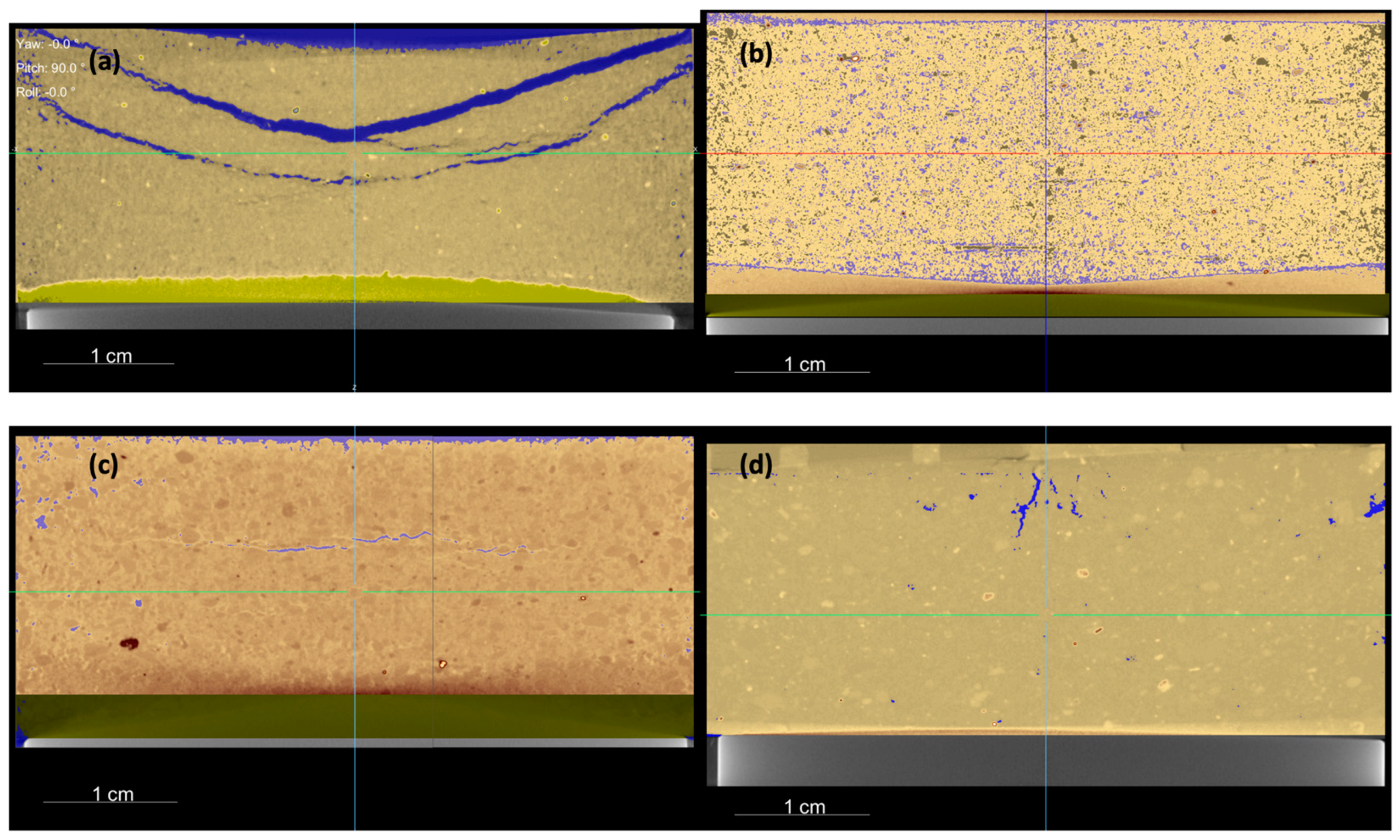
Micro-computed X-ray tomography (µ-CT) (Madrid, Spain) was used to analyze the columns for both bentonites, before and after the experimental time. This non-destructive technique enables the observation of how the FeCl2 powder is distributed along the bentonite and the evolution of the porosity. This analysis was conducted at the Centro Nacional de Investigación de la Evolución Humana (CENIEH) using a MicroCT V|Tome|x S240 Phoenix X-ray from GE Sensing & Inspections Technologies. The parameters used included an isometric voxel size of 40 µm, over 600 images taken, rotation over the Z-axis, and a voltage of 210 kV. The Dragonfly software from Object Research Systems was used to perform the image treatment.
4. Discussion
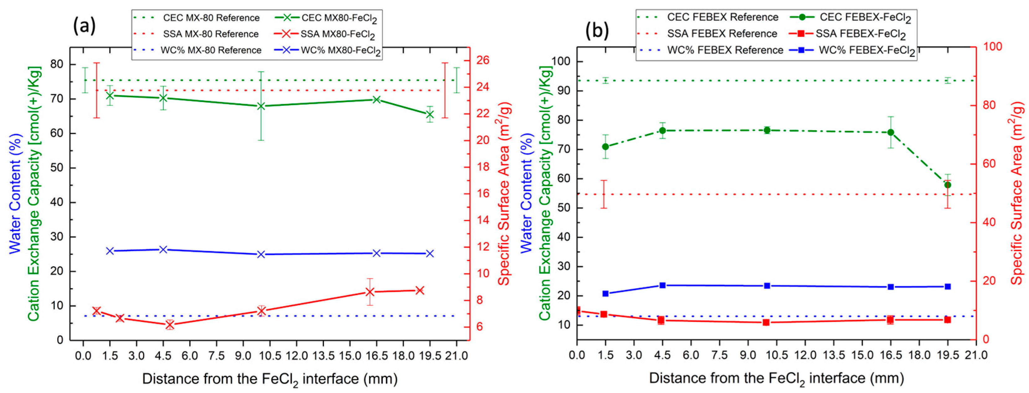
The physical–chemical properties of both bentonites were modified. The water content increased until the saturation state, and the CEC and SSA were reduced due to the hydrothermal gradient, as confirmed in previous studies [
26,
37]. The water content increased in both experiments due to the constant low pressure from the hydration tank, which permitted progressive water uptake from the bentonite. As observed in the µ-CT study, not only did the upper part of the bentonites display a larger porosity due to the initial columns setting and the contact with the hydration solution but this also occurred in the internal boundaries of the Teflon cells in contact with the bentonites. Therefore, the water migration from the top could have reached the bottom of the cells during the first stages, creating a preferential path for hydration, which could also have promoted the dissolution of the FeCl
2 and its transport along the bentonite column. At a heater temperature of 100 °C, water vapor might have been generated and moved through pores to condense in cooler regions [
53]. After 6 months of reaction, the water content was similar in both bentonites, and, according to the mass balance calculations, the initial free pore space present in both cells was not only fully saturated by the incoming hydration solution but rather the cells had to increase in volume, as was possible to determine using µ-CT. Moreover, an expansion of nearly 3% in the FEBEX bentonite and 5% in the MX-80 bentonite could be quantified due to swelling.
The decrease in the SSA in both bentonites along the whole block was caused by the mobilization of the FeCl
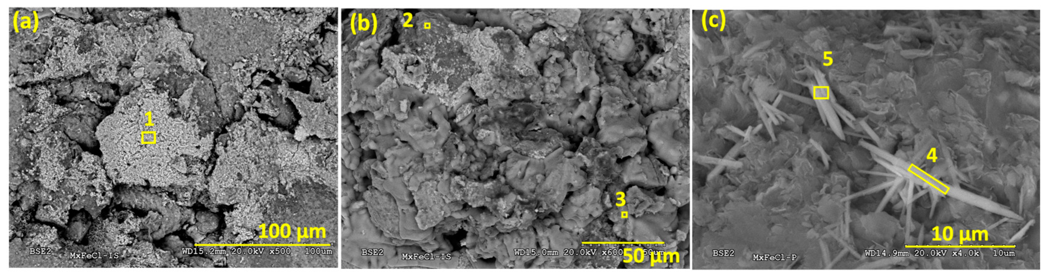
2 due to the bentonite’s porosity and, presumably, the adsorption of oxy-hydroxides or the precipitation of neoformed iron silicates near the montmorillonite surface, as observed using SEM-EDX, and confirmed using XRD. The observations performed using SEM-EDX confirmed the interactions of the FeCl
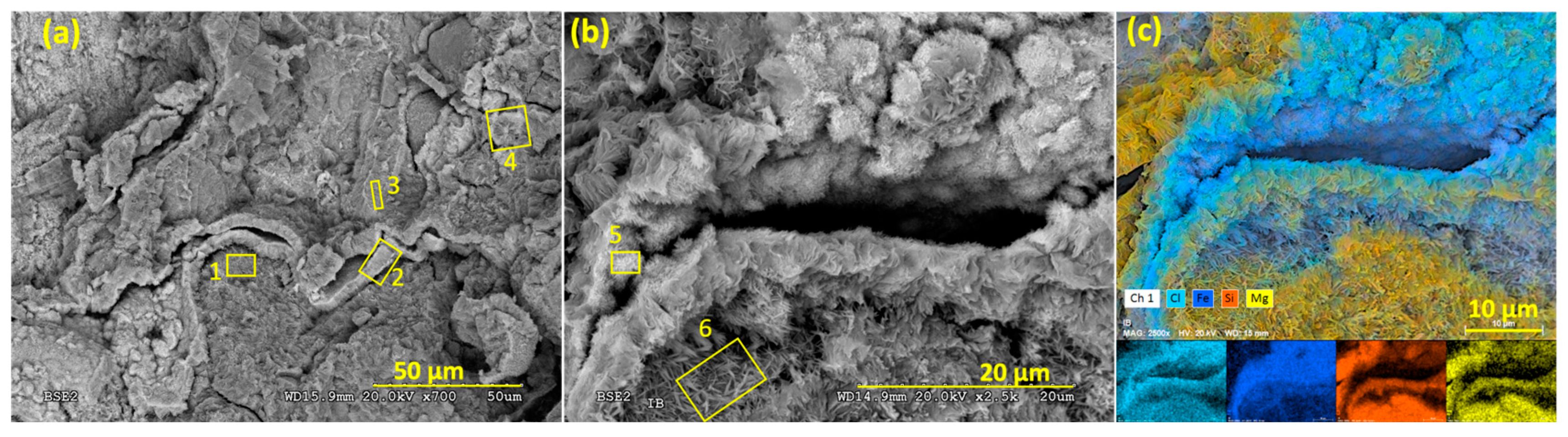
2 with the montmorillonite, showed the precipitation of Fe-Cl corrosion products, and evidenced chloritization processes, although these could not be firmly confirmed using XRD. The formation of Fe spicules or fibrous Fe silicates was reported according to SEM observations in a previous study of Fe–bentonite interaction [
54].
The CEC decreased in both bentonites. This phenomenon is usually associated with montmorillonite dissolution or variations in the layer charge. However, the CEC decrease in the present study is not associated with montmorillonite dissolution because there was no evidence of this observed according to any of the analytical methods used in the present work. After 18 years of exposure to a C-steel heater at 100 °C in an in situ FEBEX experiment, a reduction in the CEC was noted in FEBEX bentonite [
55]. The authors of the study attributed this phenomenon to one of the following: an increase in the smectite layer charge by means of the reduction of the FeIII-bearing smectite, which caused interlayer collapse, or the collapse of the clay particles, induced by a large ionic strength, which generally reduces the swelling pressure [
56]. In the present study, the decrease in the CEC was almost constant in MX-80 in the whole bentonite column. In the FEBEX bentonite, the decrease was almost constant except in the section closest to the hydration zone; therefore, it could be attributed to a higher salinity due to the direct contact with the saline solution. Nevertheless, this was not confirmed, and other possible reactions, such as the fixation of the interlayer cations (Fe
2+), could have affected the CEC.
Dohrmann et al. [
57] suggested the possibility of a reduction in the CEC due to the elevated temperature of the experiments and/or the formation of corrosion products in the bentonite matrix, creating alkaline conditions that could not be confirmed experimentally in the present study, as the pH could not be measured without altering the experimental redox conditions.
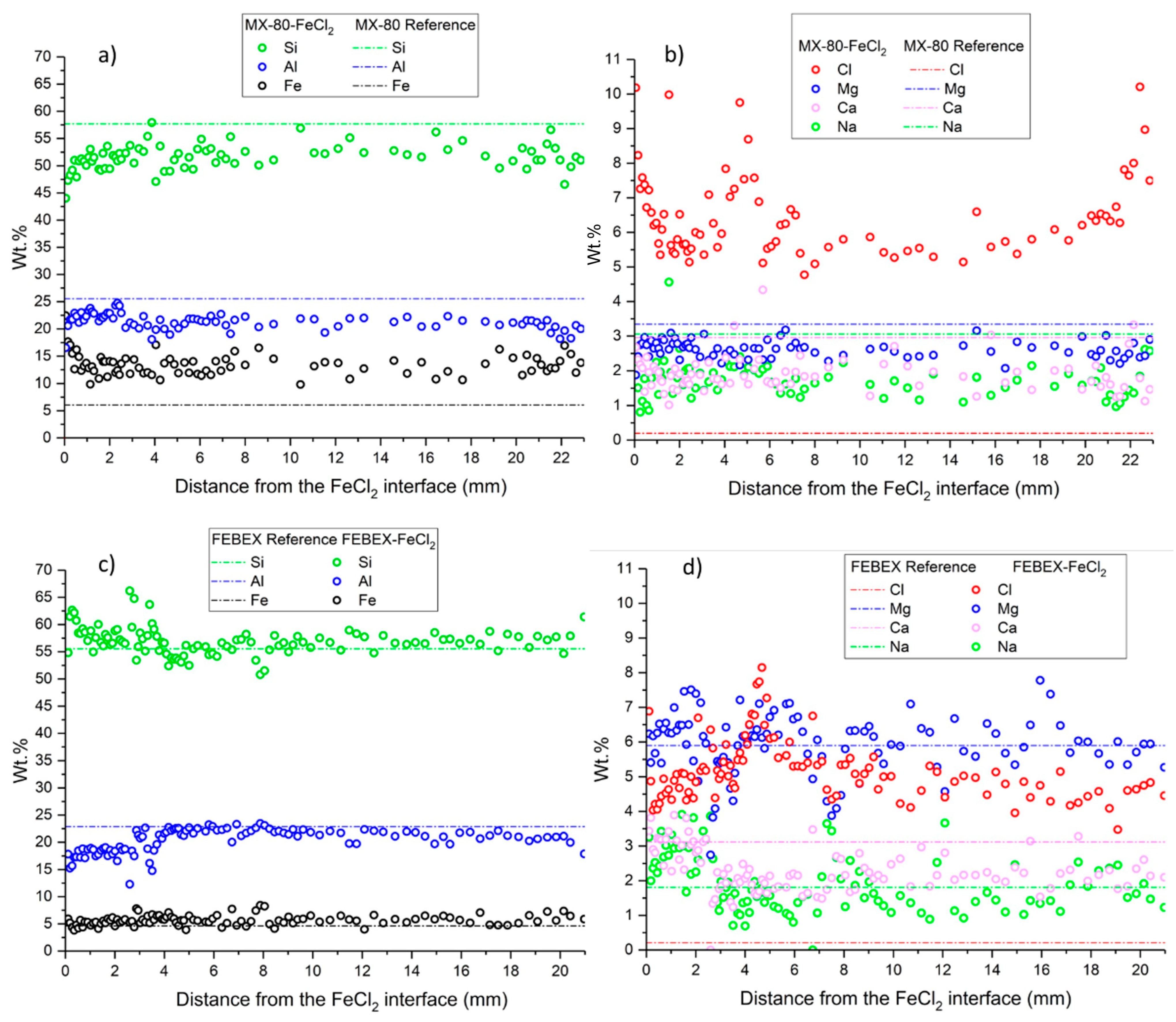
The enrichment in divalent montmorillonite, regarding the initially monovalent MX-80 bentonite, could be explained by the ion exchange between the soluble divalent cations (Fe(II), Ca, Mg) and exchangeable Na in the interlayer complex [
37,
58]. This exchange could be enhanced by the hydration and dissolution of soluble salts like gypsum and calcite, present in the original bentonite, and, for instance, the exchange of FeCl
+ complexes in the montmorillonite [
59]. The precipitation of halite observed using SEM/EDX and confirmed using XRD, due to the high concentrations of chloride in the system, favored the exchange complex to counteract the cation charge for the divalent cation species.
The increase in Fe content within the montmorillonite structure could be elucidated according to various mechanisms, such as the adsorption within the interlayer via cation exchange, adsorption at the edge sites of the montmorillonite, or association with newly precipitated oxides [
60]. Additionally, redox reactions may have been produced, leading to the precipitation of Fe
III oxides or mixed Fe
II/Fe
III oxides. Soluble Fe
2+ migrated into the bentonite, and as oxygen from the bentonite pores diffused into the FeCl
2 powder, the interaction of iron with oxygen could have resulted in oxidation and subsequent precipitation on the montmorillonite surface, forming iron (hydr)oxides, as observed. The use of FeCl
2 powder instead of Fe
0 powder or metal plates provided faster mobilization due to its solubility in water and the imposed hydrothermal gradient. This factor allowed a higher reactivity, with Fe interacting along the whole bentonite columns and not only in the mm closer to the heater, as occurred in more realistic experiments [
22,
29,
61,
62]. It is worth mentioning that initially, the monovalent MX-80 bentonite favored Fe
2+ exchange and a more intense (in quantity) diffusion of the ion through the whole compacted bentonite material. The original divalent FEBEX bentonite allocated much less iron relative to MX-80, as shown by the EDX elemental profiles.
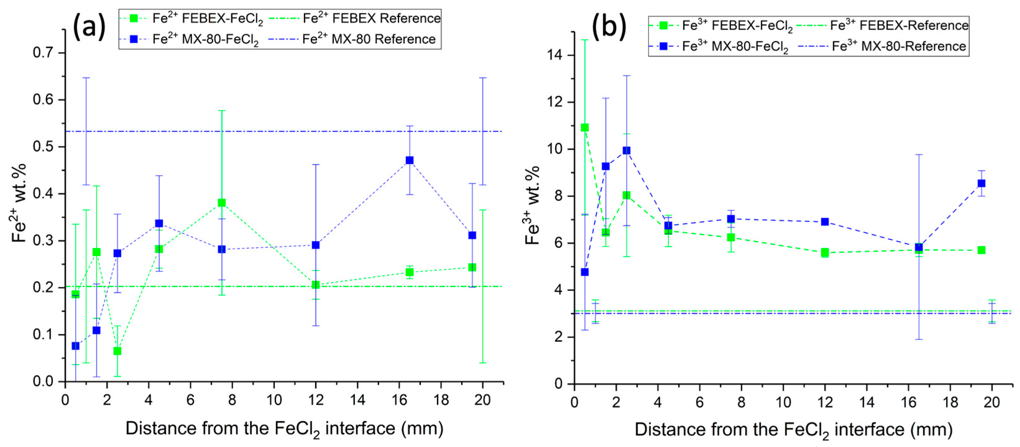
Determinations of the redox state of iron analyzed using the redox indicator 1,10-phenanthroline showed that Fe
2+ was mainly concentrated in the middle sections of the bentonite block. This may be due to the oxidation of Fe
2+ into Fe
3+ in the sections close to the FeCl
2, as the hydration solution moved from the upper part to the bottom, preferentially through the external boundaries of the bentonite column, and could have migrated, dissolving the initial oxygen present in the bentonite pores, favoring oxidation conditions at the bottom of the cell. Wersin et al. [
16] found that the iron in the zone closest to the heater was preferentially Fe
3+, which is consistent with the detection of hematite and goethite in this zone. Through the interaction with the bentonite, Fe
2+ was oxidated partially into Fe
3+ in the middle section of the bentonite block, coexisting with both species. However, the Fe
3+ concentrations were much higher than those of Fe
2+, due to the oxidation of Fe
2+ into Fe
3+ [
16].
Considering the Fe2+ and Fe3+ data obtained in the present study, a mass balance calculation over the whole bentonite column indicated that MX-80 increased in its overall Fe3+ content by 137%, decreasing, meanwhile, in its Fe2+ content by 42%. Consistently, the Fe3+ content in the FEBEX bentonite increased by 101%, but the Fe2+ also increased by 24%.
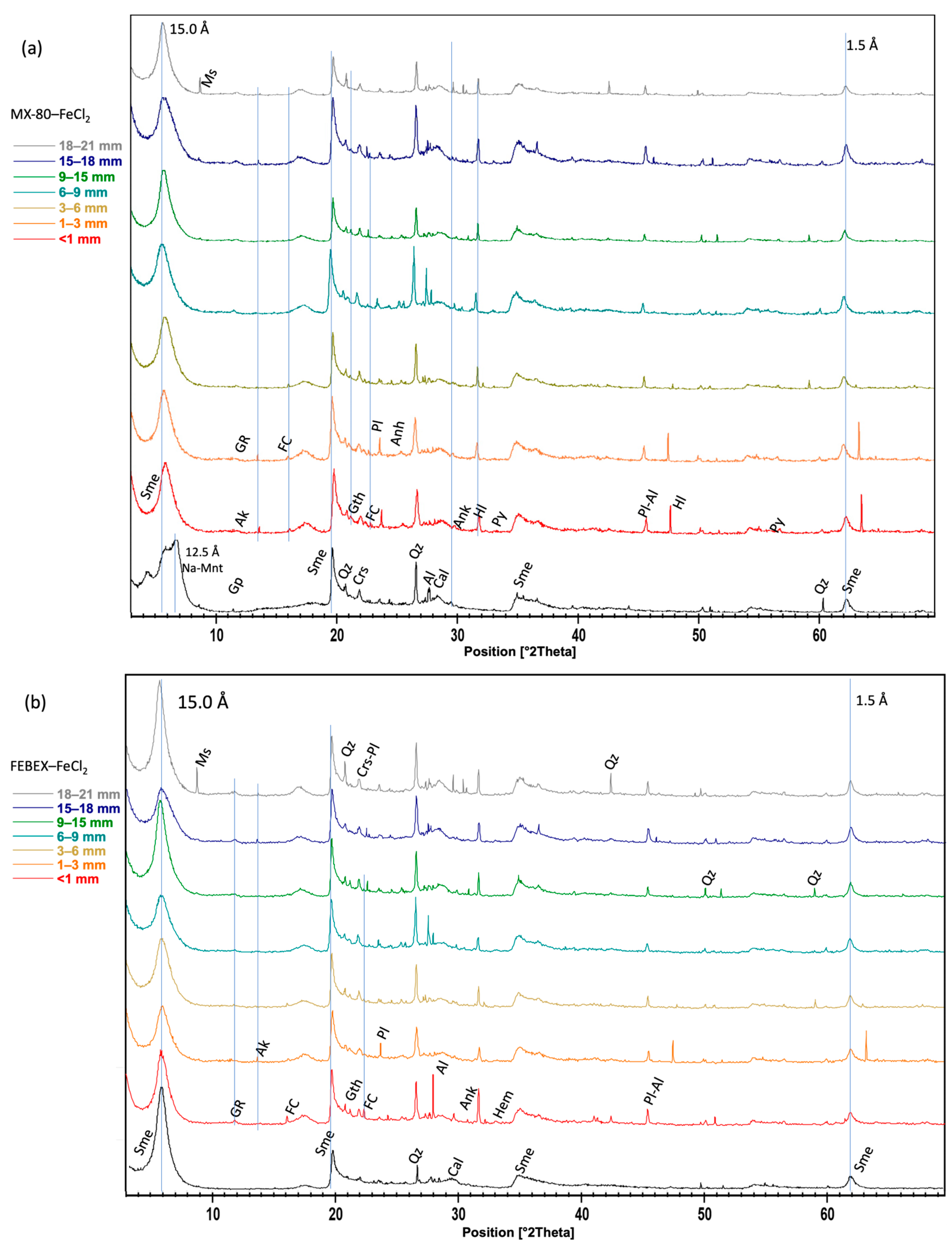
Considering the large amount of reactive iron introduced into the system in highly saline conditions, both bentonites presented a high mineralogical stability and also a large swelling capacity, as far as the initial macroporosity of the bentonites was reduced in both experiments due to their swelling capacities. Not many differences were found in their response to aggressive conditions, but a higher net increase in Fe was observed using EDX analyses in the MX-80 bentonite, and a larger conversion of FeII into FeIII. The identification of newly formed minerals in the bentonites was very limited to the contact with the FeCl2 and barely distinguishable in some cases, but green rust, ankerite, and hematite corrosion products were found in both bentonites, and iron-containing particles were observed using SEM, covering the clay surfaces. Goethite, also considered a corrosion product, was observed not only at the interface with the FeCl2 but up to 15 mm from the interface. Additionally, pyrite and a Fe-rich chlorite phase were detected in MX-80.
Due to the use of FeCl
2, the content in Cl
− increased considerably, as determined in all samples in the aqueous extracts. The XRD powder analyses showed akaganeite as an oxyhydroxide iron with chloride and hydrated iron chloride. In the MX-80 bentonite, Cl was also present in halite. Ankerite was slightly detected using XRD in the section closest to the heater. These minerals had been reported by Acosta et al. [
63], supporting that Ca
2+ could interact with Fe
2+ and form ankerite if there was CaCO
3 in the medium. Raw bentonite had calcite as an accessory mineral. This hypothesis was not confirmed according to the other techniques in this work. The formation of green rust, observed using XRD in both bentonites, MX-80 and FEBEX, near the interface with FeCl
2 was indicative of local reducing conditions, which occur when the oxygen initially present in the air-filled gaps and pores of bentonite has been consumed and has been associated, in similar studies, to the formation of magnetite and siderite, via the reduction of previously formed Fe(III) oxides (e.g., [
16]). The SEM/EDX analyses revealed the presence of polygonal pyrite framboids in the MX-80 bentonite at the contact with the FeCl
2. The formation of this secondary mineral was also observed in [
36] and suggested the likelihood of local reducing conditions. This presence of pyrite differs from that determined using XRD throughout the whole MX-80 bentonite column, which was initially present as an accessory mineral. Alternatively, pyrite formation could indicate the presence of sulfate-reducing bacteria capable of reducing the sulfates from the porewater, which seems implausible since the activity of these microorganisms at elevated temperatures is unlikely to occur and was not observed in bentonite samples from an in situ FEBEX experiment heater [
64].
5. Conclusions
The experimental design facilitated the study of the hydrothermal alterations in bentonites and investigation of the impacts produced by the use of iron(II) chloride powder as the source of soluble iron, instead of steel or iron powder, designed to mimic an EBS system, as it is considered in a real scenario.
The main consequence observed due to the hydrothermal gradient after 6 months was the partial dissolution of the FeCl2 powder in the studied cells and its diffusion through the bentonites. Iron II and III chlorides were redistributed and precipitated in addition to halite, favored by evidence of the Na exchanged by the divalent cations, although this was not experimentally determined. Iron oxides with akaganeite were identified near the heat source with the detection of small amounts of serpentine-like minerals.
Considering the large amount of reactive iron introduced into the system in highly saline conditions, both bentonites presented high mineralogical stability and also a large swelling capacity, as far as the initial macroporosity of the bentonites was reduced in both experiments due to their swelling capacities. Not many differences were found in their response to aggressive conditions, but a higher net increase in Fe was observed according to the EDX analyses in the MX-80 bentonite, and a larger conversion of FeII into FeIII. The identification of newly formed minerals in bentonite was very limited to the contact with the FeCl2 and barely distinguishable in some cases, but green rust, ankerite, and hematite corrosion products were found in both bentonites, and iron-containing particles were observed using SEM, covering the clay surfaces. Goethite, also considered a corrosion product, was observed not only at the interface with the FeCl2 but up to 15 mm from the interface. Additionally, pyrite and a Fe-rich chlorite phase were detected in MX-80.
The effects of FeCl2’s interaction with both bentonites resulted in a decrease in the specific surface area and cation exchange capacity.
The nature of the unsaturated compacted bentonites and the fluid transport through the cells possibly generated more oxic conditions than initially expected. Nevertheless, this study provides valuable insights into the intricate interactions and modifications that occur in bentonites subjected to FeCl2 alteration hydrothermal conditions, revealing the influence of the different bentonites used. The use of FeCl2 as the soluble iron emphasizes the complexity of these processes and insists on the need for a thorough understanding in the context of waste repository design and management. The geochemical processes and mineral phases observed in the present work could be useful for improving geochemical modeling studies, including the decrease in the CEC and SSA, the increase in water content and swelling, and the local redox environments required for the precipitation of secondary minerals.


