Article

Mechanical Behavior Analysis of Fully Grouted Ground Anchor in Soft-Hard Alternating Stratum

1
State Key Laboratory for Geomechanics and Deep Underground Engineering, China University of Mining and Technology, Xuzhou 221116, China
2
Shenzhen Geotechnical Investigation & Surveying Institute (Group) Co., Ltd., Shenzhen 518028, China
*
Authors to whom correspondence should be addressed.
Minerals 2023, 13(1), 59; https://doi.org/10.3390/min13010059
Submission received: 30 November 2022 / Revised: 26 December 2022 / Accepted: 28 December 2022 / Published: 29 December 2022
(This article belongs to the Topic Support Theory and Technology of Geotechnical Engineering)

Abstract

:
Assuming that the ground anchor is connected with the rock–soil of the sidewall by a tangential linear spring, the load transfer model of the fully grouted ground anchor is established by using the spring element method, and the analytical solutions of the displacement, axial force, and shear stress distribution of the ground anchor in the upper and lower parallel strata foundation and sandwich foundation are given, respectively. Corresponding to the above two kinds of alternating strata, the mechanical behavior of the vertical fully grouted ground anchor in the soft–hard alternating stratum is analyzed using the four conditions in Case 1 and the six conditions in Case 2, respectively. Through the case analysis, it can be concluded that the mechanical behavior of the round anchor is greatly affected by the shear modulus of the shallow stratum, and is less affected by the shear modulus of the deep stratum. The depth of the stratum interface and the thickness of the interlayer have some influence on the mechanical behavior of the whole ground anchor but have little influence on the displacement and axial force distribution of the ground anchor. This paper has certain guidance and reference significance for the design of vertical fully grouted ground anchors in the alternating strata.

1. Introduction

In recent years, geotechnical anchoring technology has developed rapidly, and anchors are widely used in reinforcement projects, such as in civil engineering and mining. Three main types of anchoring technology are widely used at present: mechanical anchoring, grouting, and friction anchoring. Among these, grout anchoring is the most popular in practice due to its ease of installation, relatively low cost, and versatility in applications [1]. Among the various types of anchors, fully grouted anchors are the most common in practical applications. A fully grouted anchor is an anchor that is inserted and grouted in a borehole along the entire length [2]. The bearing performance of fully grouted anchors mainly depends on the type of steel bar, the grout material, and the lithology of the formation. Having a better understanding of the anchor load transfer mechanism can help to optimize the anchor profile design, which can significantly improve the performance of the rock anchor reinforcement system [3].
Understanding the load transfer mechanism of the anchor can be accomplished by using methods such as field tests, numerical simulations, and theoretical analysis. In the field testing of anchors, much experimental research work has been carried out [4,5,6,7,8,9,10]. These research results have laid a good foundation for the theoretical analysis of fully grouted anchors. Much work has also been conducted on the theoretical analysis of the load transfer mechanism of fully grouted anchors. Phillips [11] and Farmer [12] proposed the exponential function form of the shear stress distribution at the anchor interface. Starting from the displacement solution of Mindlin, scholars such as Wijk [13] deduced the details of the solution of the axial force and shear stress distributed along the anchoring section of the anchor. Aydan et al. [14] assumed that the rock mass, grout, anchor, and interface between them are all in an elastic working state, and established the solution of the drawing load distribution of the anchor. Li and Stillborg [15] proposed an analytical model for fully grouted rock anchors under tensile load based on the shear stress distribution along the anchor, successfully accounting for decoupling at the anchor–rock interface. Ren et al. [1] used the tri-linear shear–slip model of the anchoring interface to establish an analytical solution of the axial force and shear stress distribution of the anchored section in the fully elastic, elastoplastic, and fully plastic states. Ma et al. [3] used a nonlinear shear–slip model to conduct a preliminary analysis of the load transfer and nonlinear characteristics of full-length bonded anchors under pull-out load. Chen et al. [16] used a tri-linear model to consider the elastic, softening, and debonding behaviors at the cable–grout interface, and proposed an analytical model for fully grouted anchors under axial load conditions. Li et al. [17] proposed a novel constitutive model to characterize the mechanical behavior of cable anchors under axial load and subjected to different boundary conditions, including constant confining pressure and constant normal stiffness. Jahangir et al. [18] proposed a new interface constitutive model for fully grouted rock anchors and cable anchors based on pull-out test results. A database was created combining published experimental data with in-house tests. In addition, many field tests and theoretical research on fully grouted anchors have been conducted, which will not be mentioned here.
In the previous theoretical research work, in order to simplify the calculation, it is often assumed that the rock and soil around the anchor are homogeneous. However, in practical projects, it is often encountered that the anchor is embedded in the soft–hard alternating layer foundation. Engineering experience shows that the shear modulus of rock and soil around the anchor has a greater impact on the bearing characteristics of the anchor. At this time, if the rock and soil around the anchor are still assumed to be homogeneous in the design, it is bound to cause a large deviation between the theoretical calculation results and the actual situation, thus laying unnecessary hidden dangers for the project’s safety. Guo et al. [19] studied the pullout force of tension-type ground anchors with anchor sections crossing two soil strata, but the model they proposed is a semi-analytical method, which is not rigorous in theory. Moreover, their focus was mainly on the ultimate bond strength, and they did not discuss the influence of the difference in the shear modulus of the two strata on the mechanical behavior of the bolt. Therefore, in order to more deeply understand the load transfer mechanism of fully grouted anchors in the soft–hard alternating stratum, it is essential to analyze and study its mechanical behavior characteristics in the soft–hard alternating stratum.
In the following sections, we introduce a method for analyzing the force of anchors, the spring element method, which is based on the idea of discretization and force balance analysis of each mass spring element. It is assumed that the ground anchor and the sidewall rock and soil are connected by tangential linear springs, and the load transfer model of the fully grouted ground anchor is established by the spring element method. Then, using the load transfer model, the analytical solutions of the mechanical behavior of the ground anchor in the upper and lower parallel strata foundation and the sandwich foundation are derived, respectively. Finally, the influence of the variables such as the shear modulus of the stratum and the depth of the stratum interface on the mechanical behavior of the vertical fully grouted ground anchor is discussed by using the four conditions in Case 1 and the six conditions in Case 2, respectively.

2. Theoretical Model

The authors have put forward a method for mechanical analysis of grouted anchors—spring element method and studied the mechanical behavior of fully grouted ground anchors in homogeneous strata under axial cyclic load [20]. In this paper, the spring element method is applied to the study of the mechanical behavior of fully grouted ground anchors in soft and hard alternating strata as a continuation of the previous study. The following is a brief creation process of the spring element method.

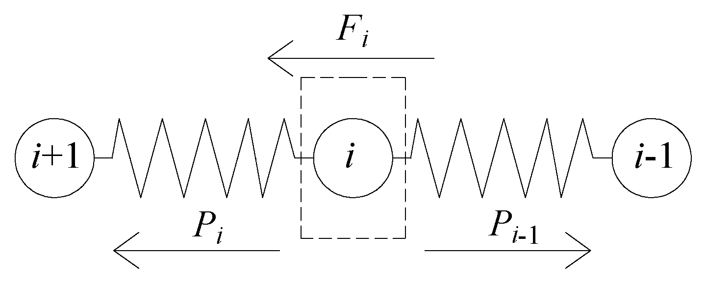
2.1. Analysis of Anchor Force

As shown in Figure 1, a homogeneous free bar with equal cross-section can be discretized into n mass-point spring elements with the same stiffness k. Each spring element is composed of a spring and an infinitesimal mass point. In the free state, its length is the same as that of the free bar micro-segment, and the external force on each bar micro-segment is concentrated on the mass point of the corresponding spring element. After the same tensile force P is applied at both ends, the bar is elongated by s, and the elongation Δsi of each spring element can be obtained according to Hooke’s law as
Δ s i = P l n E A
where E is the elastic modulus, A is the cross-sectional area, and l is the length of the bar.
Then, the stiffness of each spring element is
k = n E A l
Similarly, as shown in Figure 2, a homogeneous anchor of equal sections can also be discretized into n spring elements with the same stiffness. Since the anchor is constrained by the sidewall, after tensile force P is applied to the top of the anchor, the elongation Δsi of each spring element is not equal at this time, and
Δ s i = P i k
where Pi is the spring tension of the ith spring element.
Number the spring elements from 1 to n starting from the place where the load is applied. Then, the displacements of the ith and i + 1th spring elements are related as follows:
s i s i + 1 = Δ s i
Figure 3 shows the force analysis diagram of the ith spring element. The following relationship can be seen from Figure 3:
F i = P i 1 P i
where Fi is the lateral resistance provided by the sidewall to the ith spring element.
Combining Equations (3) and (5), we obtain
Δ s i 1 Δ s i = F i k
When n → ∞, the discrete spring element can be transformed into a continuous anchor again. Then Equations (3) and (6) can be, respectively, transformed into
s ( x ) = P ( x ) k u
s ( x ) = F ( x ) k u
In these formulas, P(x) is the distribution function of anchor axial force, F(x) is the distribution function of side resistance, s′(x) is the first derivative of the displacement distribution function s(x), s″(x) is the second derivative of s(x), x is the length from the top of the anchor, ku is the stiffness of the anchor per unit length, namely, ku = kl/n = EA.

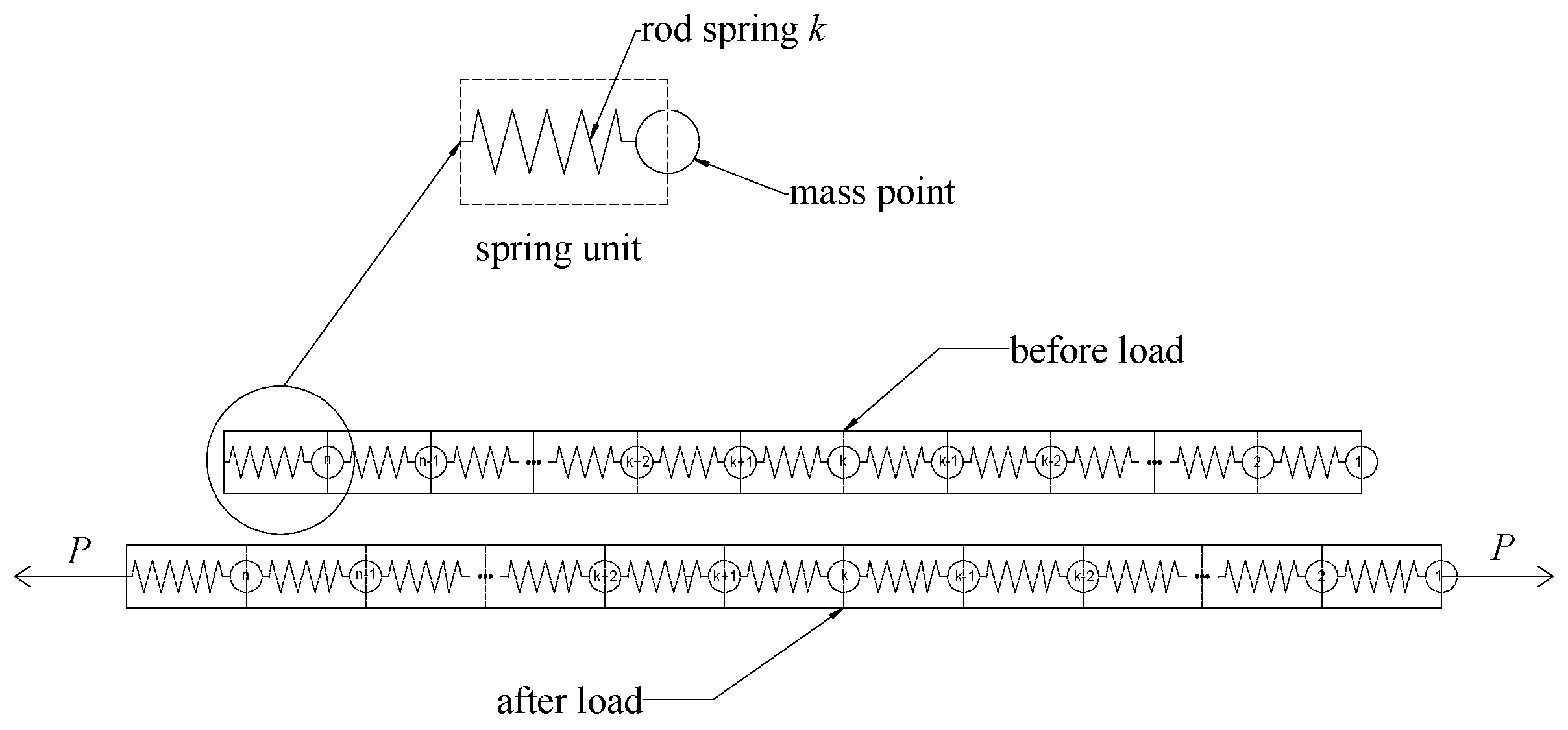
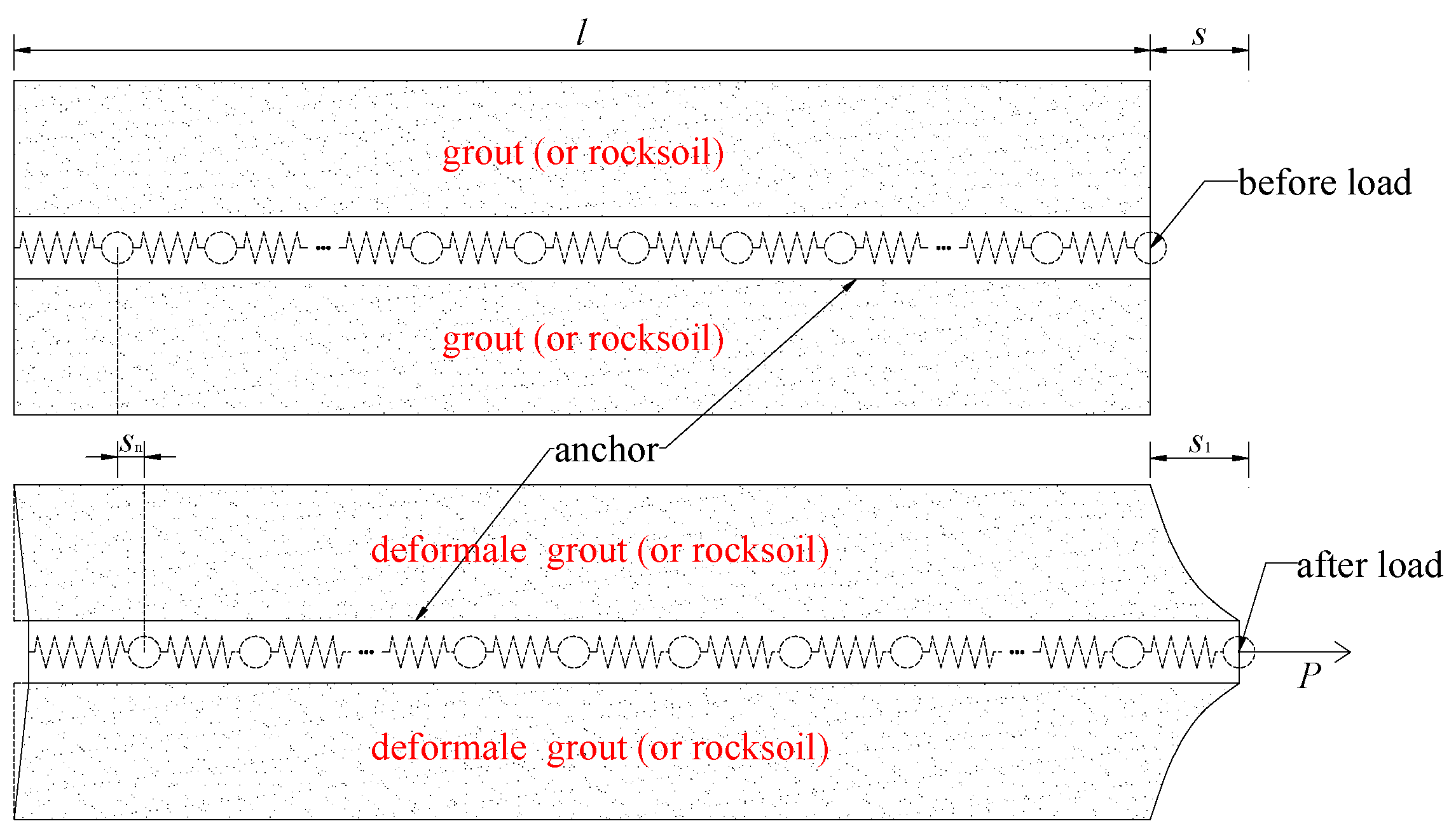
2.2. Establishment of Load Transfer Model

Many scholars [21,22,23] have studied the mechanical properties of the anchor shear interface, and it is believed that the change law is as follows: with increased shear displacement, the shear stress increases almost linearly; when maximum shear stress τf is reached, as the displacement increases, the shear stress decreases until the residual strength is reached. Because our research object is the influence of the change of the shear modulus ratio of the alternating stratum on the mechanical behavior of the vertical fully grouted anchor, we only consider the situation of the anchor in the elastic deformation stage for convenience, that is, the situation of the anchor debonding or decoupling is not considered. Based on this law, it is assumed that the anchor and the rock–soil mass are connected by tangential linear springs. The shear displacement between the anchor and the sidewall is coordinated, then
F ( x ) = k u s ( x )
where ku is the shear spring stiffness per unit length between anchor and rock–soil.
Cai et al. [23] deduced an empirical formula for calculating sidewall spring stiffness ku by analyzing the stress state of the rock mass unit around the anchor, based on the force balance conditions and approximate assumptions. When the grout has the same characteristics as the rock soil, we have
k u = 2 π G g ln ( R r b )
and when the properties of the grout and the rock soil are different, we have
k u = 2 π G g G r G g ln ( R r g ) + G r ln ( r g r b )
in which Gg is the shear modulus of the grout, Gr is the shear modulus of the rock soil, rg is the radius of the borehole, and R is the influence radius of the anchor, that is, the radius of the deformation zone.
Substituting Equation (9) into Equation (8), the anchor load transfer equation at this time can be obtained as
s ( x ) k u k u s ( x ) = 0
The general solution to the above equation is
s ( x ) = A 1 e λ x + A 2 e λ x
where A1 and A2 are the parameters to be sought, and λ = k u / k u .
It is known that the boundary conditions are
s ( x ) | x = 0 = P 0 k u
s ( x ) | x = l = 0
where s0 and P0 are the displacement and pull-out force at the top of the anchor, respectively.
Substituting boundary condition Equations (14)–(15) into Equation (13), we obtain A 1 = P 0 λ k u e λ l e λ l e λ l ;   A 2 = P 0 λ k u e λ l e λ l e λ l .
Then the displacement distribution function of the anchor can be obtained as
s ( x ) = P 0 λ k u ch [ λ ( l x ) ] sh ( λ l )
where sh () is the abbreviation of hyperbolic sine function sinh (), and ch () is the abbreviation of hyperbolic cosine function cosh ().
Taking the derivative of x on both sides of Equation (16), and substituting s′(x) into Equation (7), the axial force distribution function of the anchor can be obtained as
P ( x ) = P 0 sh [ λ ( l x ) ] sh ( λ l )
Substituting Equation (16) into Equation (9), we can obtain the shear stress distribution function of the anchor as
τ ( x ) = P 0 λ 2 π r b ch [ λ ( l x ) ] sh ( λ l )
where rb is the radius of the anchor.

3. Analytical Solution of Mechanical Behavior of Fully Grouted Ground Anchor in Alternating Stratum

For the convenience of research, this paper only analyzes the following two kinds of alternating strata.

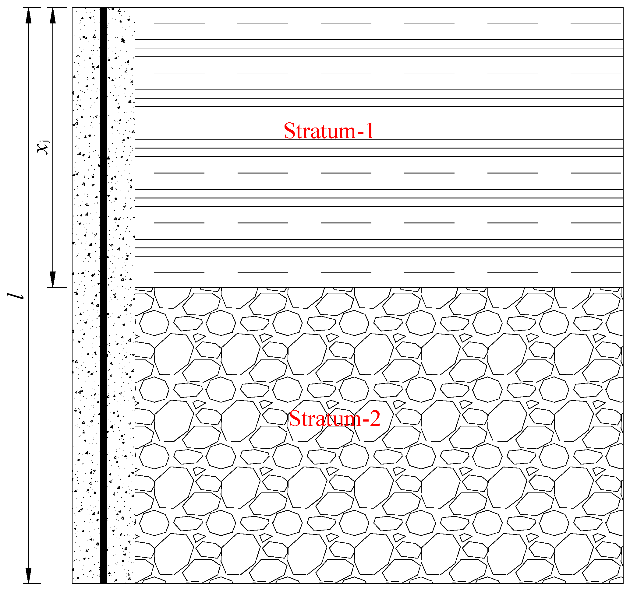
3.1. Upper and Lower Parallel Stratum Foundation

As shown in Figure 4, the vertical fully grouted ground anchor is buried in the upper and lower parallel strata. According to the above analysis, the displacement distribution function of the ground anchor is as follows:
s ( x ) = { A 1 e λ 1 x + A 2 e λ 1 x ( 0 x x j ) A 1 e λ 2 x + A 2 e λ 2 x ( x j x l )
where A1, A2, A1, and A2 are the parameters to be sought, and λ 1 = k u 1 / k u ; λ 2 = k u 2 / k u .
Substitute the boundary condition Equations (14) and (15) into Equation (19), and consider the continuity of s(x) and P(x) at the stratum interface, so as to obtain
A 1 = P 0 e λ 1 x j 2 λ 1 k u η { ch [ λ 2 ( l x j ) ] λ 2 λ 1 sh [ λ 2 ( l x j ) ] }
A 2 = P 0 e λ 1 x j 2 λ 1 k u η { ch [ λ 2 ( l x j ) ] + λ 2 λ 1 sh [ λ 2 ( l x j ) ] }
A 1 = P 0 e λ 2 l 2 λ 1 k u η ;   A 2 = P 0 e λ 2 l 2 λ 1 k u η
in which η = sh ( λ 1 x j ) ch [ λ 2 ( l x j ) ] + λ 2 λ 1 ch ( λ 1 x j ) sh [ λ 2 ( l x j ) ] .
Then the displacement distribution function, axial force distribution function, and shear stress distribution function of the ground anchor can be obtained as
s ( x ) = { P 0 λ 1 k u η { ch [ λ 2 ( l x j ) ] ch [ λ 1 ( x j x ) ] + λ 2 λ 1 sh [ λ 2 ( l x j ) ] sh [ λ 1 ( x j x ) ] } ( 0 x x j ) P 0 λ 1 k u η ch [ λ 2 ( l x ) ] ( x j x l )
P ( x ) = { P 0 η { ch [ λ 2 ( l x j ) ] sh [ λ 1 ( x j x ) ] + λ 2 λ 1 sh [ λ 2 ( l x j ) ] ch [ λ 1 ( x j x ) ] } ( 0 x x j ) P 0 η λ 2 λ 1 sh [ λ 2 ( l x ) ] ( x j x l )
τ ( x ) = { P 0 2 π r b λ 1 ch [ λ 2 ( l x j ) ] ch [ λ 1 ( x j x ) ] + λ 2 sh [ λ 2 ( l x j ) ] sh [ λ 1 ( x j x ) ] η ( 0 x x j ) P 0 2 π r b λ 2 2 ch [ λ 2 ( l x ) ] λ 1 η ( x j x l )

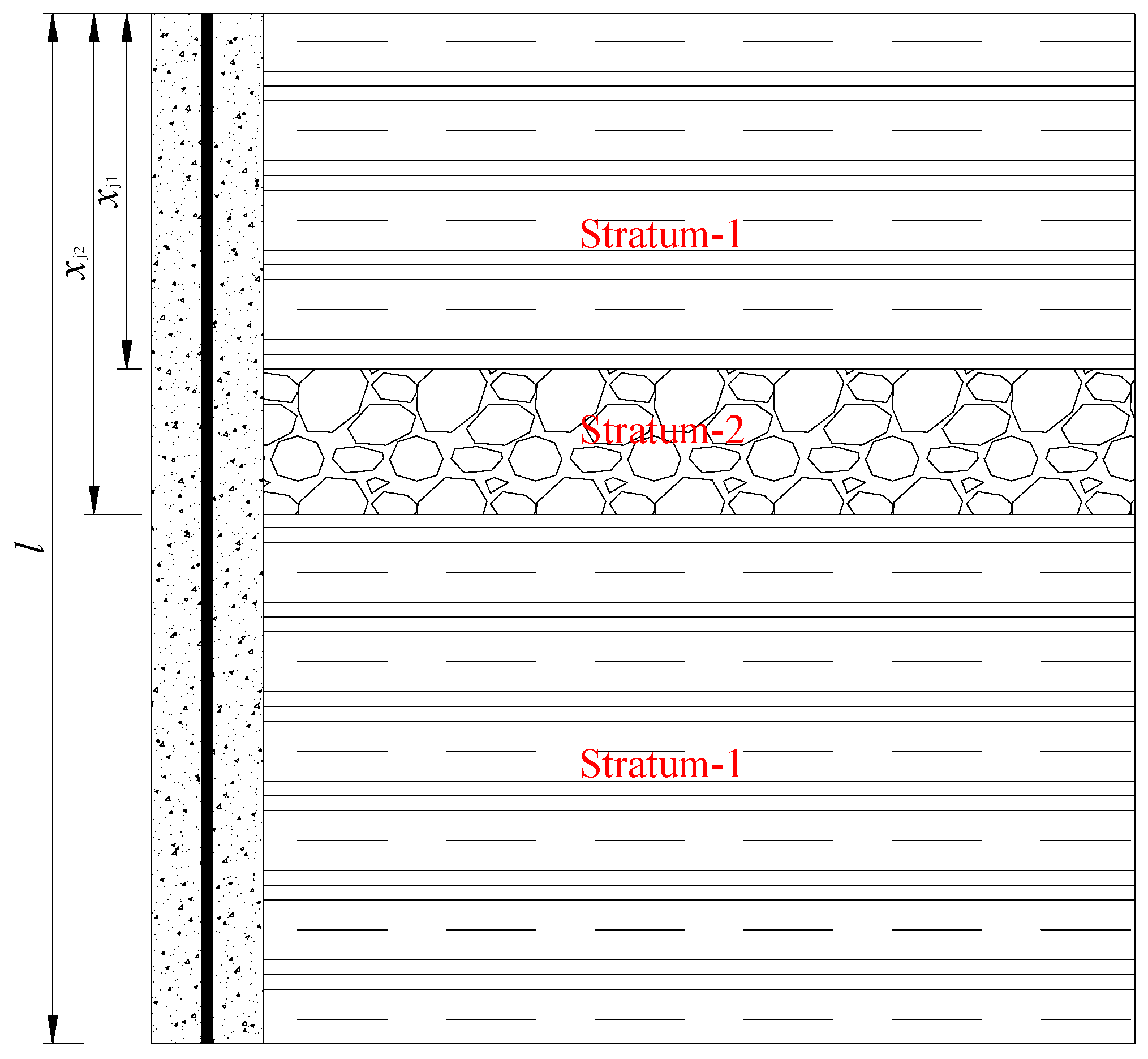
3.2. Sandwich Foundation

As shown in Figure 5, the vertical fully grouted ground anchor is buried in the sandwich foundation. Similarly, according to the above analysis, the displacement distribution function of the ground anchor is as follows:
s ( x ) = { A 1 e λ 1 x + A 2 e λ 1 x ( 0 x x j 1 ) A 1 e λ 2 x + A 2 e λ 2 x ( x j 1 x x j 2 ) A 1 e λ 1 x + A 2 e λ 1 x ( x j 2 x l )
where A1, A2, A 1 , A 2 , A 1 , and A 2 are the parameters to be sought.
Substitute the boundary condition Equations (14) and (15) into Equation (26), and consider the continuity of s(x) and P(x) at the stratum interface, so as to obtain
A 1 = P 0 e λ 1 x j 1 2 λ 1 k u κ { ch [ λ 2 ( x j 2 x j 1 ) ] { ch [ λ 1 ( l x j 2 ) ] sh [ λ 1 ( l x j 2 ) ] } + sh [ λ 2 ( x j 2 x j 1 ) ] { λ 1 λ 2 sh [ λ 1 ( l x j 2 ) ] λ 2 λ 1 ch [ λ 1 ( l x j 2 ) ] } } ;
A 2 = P 0 e λ 1 x j 1 2 λ 1 k u κ { ch [ λ 2 ( x j 2 x j 1 ) ] { ch [ λ 1 ( l x j 2 ) ] + sh [ λ 1 ( l x j 2 ) ] } + sh [ λ 2 ( x j 2 x j 1 ) ] { λ 1 λ 2 sh [ λ 1 ( l x j 2 ) ] + λ 2 λ 1 ch [ λ 1 ( l x j 2 ) ] } } ;
A 1 = P 0 e λ 2 x j 2 2 λ 1 k u κ { ch [ λ 1 ( l x j 2 ) ] λ 1 λ 2 sh [ λ 1 ( l x j 2 ) ] } ;
A 2 = P 0 e λ 2 x j 2 2 λ 1 k u κ { ch [ λ 1 ( l x j 2 ) ] + λ 1 λ 2 sh [ λ 1 ( l x j 2 ) ] } ;
A 1 = P 0 e λ 1 l 2 λ 1 k u κ ;
A 2 = P 0 e λ 1 l 2 λ 1 k u κ .
In which,
κ = ch [ λ 2 ( x j 2 x j 1 ) ] sh [ λ 1 ( l + x j 1 x j 2 ) ] + sh [ λ 2 ( x j 2         x j 1 ) ] { λ 1 λ 2 sh [ λ 1 ( l x j 2 ) ] sh ( λ 1 x j 1 ) + λ 2 λ 1 ch [ λ 1 ( l x j 2 ) ] ch ( λ 1 x j 1 ) }
Similarly, the displacement distribution function, axial force distribution function, and shear stress distribution function of the ground anchor can be obtained as
s ( x ) = { P 0 λ 1 k u κ { ch [ λ 2 ( x j 2 x j 1 ) ] { ch [ λ 1 ( l x j 2 ) ] ch [ λ 1 ( x j 1 x ) ] + sh [ λ 1 ( l x j 2 ) ] sh [ λ 1 ( x j 1 x ) ] } + sh [ λ 2 ( x j 2 x j 1 ) ] { λ 1 λ 2 sh [ λ 1 ( l x j 2 ) ] ch [ λ 1 ( x j 1 x ) ] + λ 2 λ 1 ch [ λ 1 ( l x j 2 ) ] sh [ λ 1 ( x j 1 x ) ] } } ( 0 x x j 1 ) P 0 λ 1 k u κ { ch [ λ 1 ( l x j 2 ) ] ch [ λ 2 ( x j 2 x ) ] + λ 1 λ 2 sh [ λ 1 ( l x j 2 ) ] sh [ λ 2 ( x j 2 x ) ] } ( x j 1 x x j 2 ) P 0 λ 1 k u κ ch [ λ 1 ( l x ) ] ( x j 2 x l )
P ( x ) = { P 0 κ { ch [ λ 2 ( x j 2 x j 1 ) ] { ch [ λ 1 ( l x j 2 ) ] sh [ λ 1 ( x j 1 x ) ] + sh [ λ 1 ( l x j 2 ) ] ch [ λ 1 ( x j 1 x ) ] } + sh [ λ 2 ( x j 2 x j 1 ) ] { λ 1 λ 2 sh [ λ 1 ( l x j 2 ) ] sh [ λ 1 ( x j 1 x ) ] + λ 2 λ 1 ch [ λ 1 ( l x j 2 ) ] ch [ λ 1 ( x j 1 x ) ] } } ( 0 x x j 1 ) P 0 κ { λ 2 λ 1 ch [ λ 1 ( l x j 2 ) ] sh [ λ 2 ( x j 2 x ) ] + sh [ λ 1 ( l x j 2 ) ] ch [ λ 2 ( x j 2 x ) ] } ( x j 1 x x j 2 ) P 0 κ sh [ λ 1 ( l x ) ] ( x j 2 x l )
τ ( x ) = { P 0 2 π r b · λ 1 κ { ch [ λ 2 ( x j 2 x j 1 ) ] { ch [ λ 1 ( l x j 2 ) ] ch [ λ 1 ( x j 1 x ) ] + sh [ λ 1 ( l x j 2 ) ] sh [ λ 1 ( x j 1 x ) ] } + sh [ λ 2 ( x j 2 x j 1 ) ] { λ 1 λ 2 sh [ λ 1 ( l x j 2 ) ] ch [ λ 1 ( x j 1 x ) ] + λ 2 λ 1 ch [ λ 1 ( l x j 2 ) ] sh [ λ 1 ( x j 1 x ) ] } } ( 0 x x j 1 ) P 0 2 π r b · λ 1 κ { λ 2 λ 1 ch [ λ 1 ( l x j 2 ) ] ch [ λ 2 ( x j 2 x ) ] + sh [ λ 1 ( l x j 2 ) ] sh [ λ 2 ( x j 2 x ) ] } ( x j 1 x x j 2 ) P 0 2 π r b · λ 1 κ ch [ λ 1 ( l x ) ] ( x j 2 x l )

4. Verification and Discussion

In order to verify the correctness of the above analysis model, the following fully grouted ground anchors are used for analysis and research. It is known that this ground anchor has the following parameters: ground anchor length l = 10 m; ground anchor radius rb = 18 mm; elastic modulus of ground anchor Eb = 210 GPa; drilling radius rg = 90 mm; mortar elastic modulus Eg = 20 GPa; mortar Poisson’s ratio μg = 0.25. For the convenience of research, it is assumed that no matter how the shear modulus of each stratum changes, the ground anchor will not appear debonding or decoupling under the load of 200 kN. According to the above parameters, ku = 213.8 MN was calculated. Referring to the assumption of Cai et al. [23], the influence radius of the ground anchor was taken as R = 35rb.

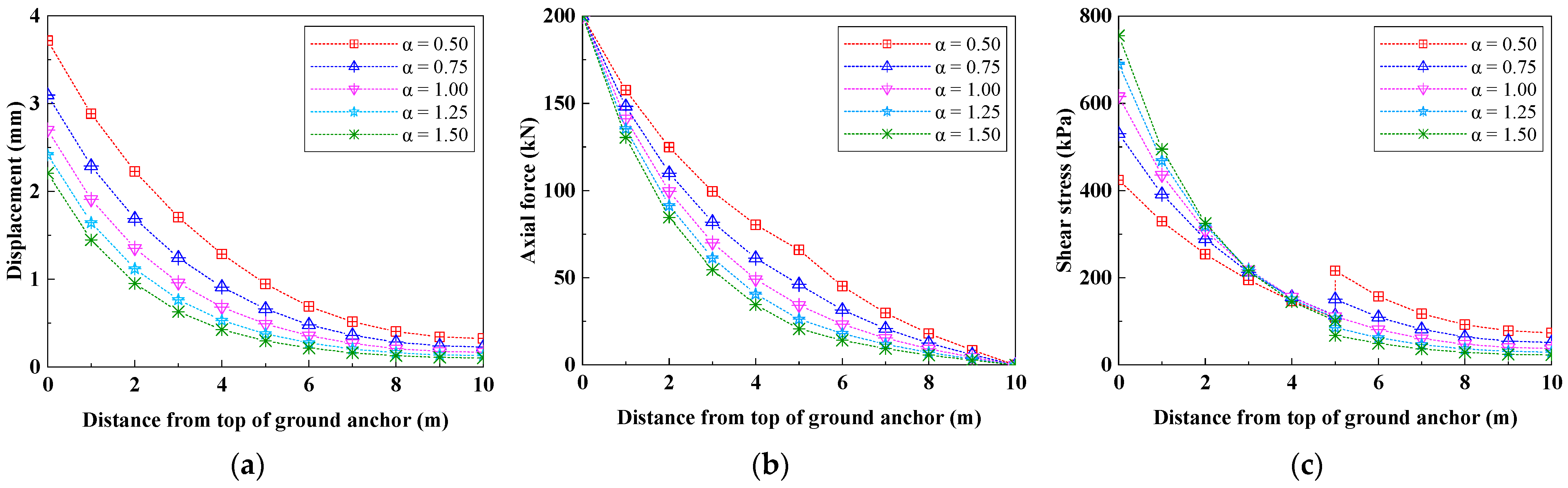
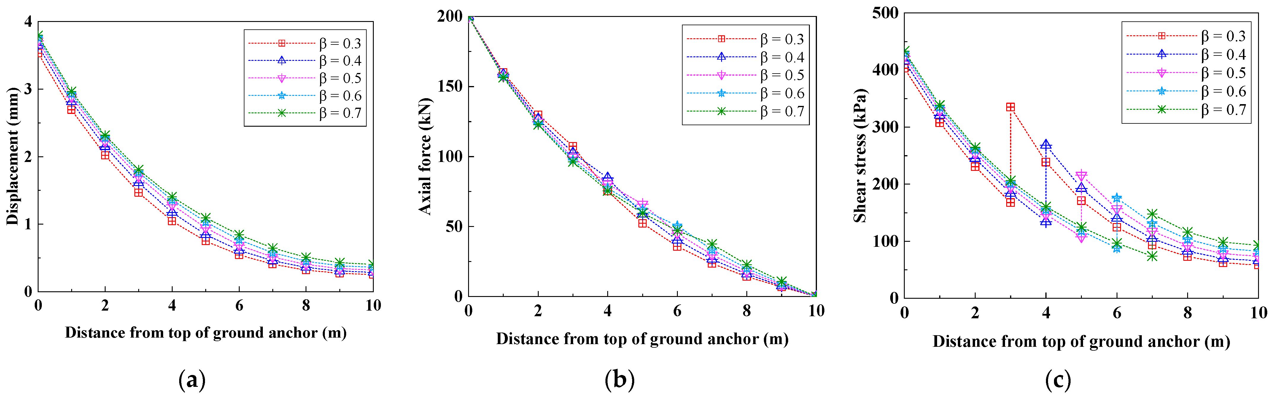
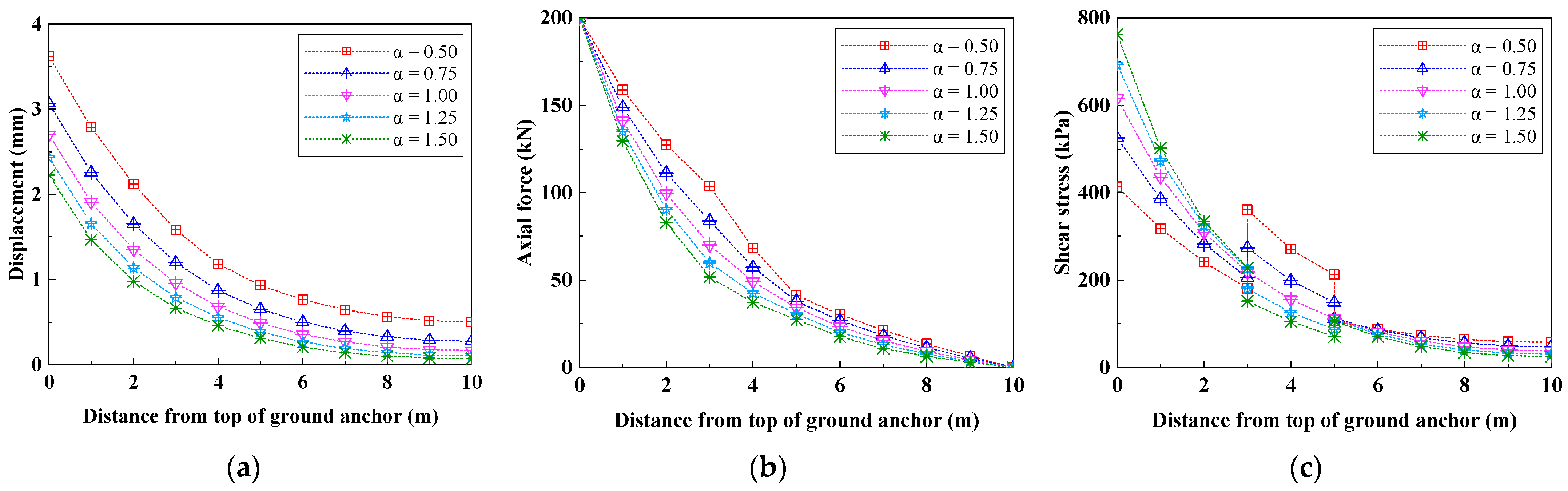
4.1. Case 1 (Corresponding to Stratum in Section 3.1)

Assume that the ground anchor is buried in the stratum as shown in Section 3.1 and discuss the influence of the change of stratum shear modulus and stratum interface depth on the mechanical behavior of fully grouted ground anchor through several special conditions listed in Table 1.
Figure 6 shows the influence of the change of Gr1 on the mechanical behavior of the ground anchor under condition 1. It can be seen from Figure 6a that with the increase of Gr1, the displacement at each depth of the ground anchor is gradually decreasing, and the upper part of the ground anchor decreases more obviously than the lower part. It can be seen from Figure 6b that, except for the top and tail of the ground anchor, the axial force at each depth of the ground anchor is gradually reduced with the increase of Gr1, and the axial force at the middle of the ground anchor is more obvious. It can be seen from Figure 6c that with the increase of Gr1, the shear stress at each depth of the ground anchor in Stratum-1 is gradually increasing, and the increase is more obvious at the top of the ground anchor; however, in Stratum-2, the shear stress at each depth of the ground anchor is gradually decreasing, especially at the stratum interface.
Figure 7 shows the influence of the change of xj on the mechanical behavior of the ground anchor under condition 2. It can be seen from Figure 7a that with the increase of xj, the displacement at each depth of the ground anchor is slightly increased, which is more obvious in the middle of the ground anchor. It can be seen from Figure 7b that with the increase of xj, the upper and lower parts of the ground anchor show two completely different change trends, but both are not very obvious. The axial force at the upper part of the ground anchor is gradually decreasing, whereas the axial force at the lower part of the ground anchor is gradually increasing. It can be seen from Figure 7c that with the increase of xj, the shear stress at each depth of the ground anchor in Stratum-1 and Stratum-2 is gradually increasing.
Figure 8 shows the influence of the change of Gr2 on the mechanical behavior of the ground anchor under condition 3. It can be seen from Figure 8a that with the increase of Gr2, the displacement at each depth of the ground anchor decreases slightly, and the lower part of the ground anchor is slightly more obvious than the upper part. It can be seen from Figure 8b that with the increase of Gr2, the axial force at each depth of the ground anchor has almost no change, and only shows a slight increasing trend in the middle of the ground anchor. It can be seen from Figure 8c that with the increase of Gr2, the shear stress at each depth of the ground anchor in Stratum-1 decreases slightly, whereas the shear stress at each depth of the ground anchor in Stratum-2 increases slightly, both of which are more obvious at the stratum interface.
Figure 9 shows the influence of the change of xj on the mechanical behavior of ground anchor under condition 4. It can be seen from Figure 9a that with the increase of xj, the displacement at each depth of the ground anchor is slightly reduced, which is more obvious in the middle of the ground anchor. It can be seen from Figure 9b that with the increase of xj, the upper and lower parts of the ground anchor also show two completely different change trends, which are not very obvious. The axial force at the upper part of the ground anchor is gradually increasing, whereas the axial force at the lower part of the ground anchor is gradually decreasing. It can be seen from Figure 9c that with the increase of xj, the shear stress at each depth of the ground anchor in Stratum-1 and Stratum-2 are gradually decreasing.
It can be seen from the comprehensive comparison of Figure 6, Figure 7, Figure 8 and Figure 9 that the change of the shear modulus of Stratum-1 has a great impact on the mechanical behavior of the ground anchor, whereas the change of the shear modulus of Stratum-2 does not have a great impact on it. Whether it is the upper soft and lower hard strata or the upper hard and lower soft strata, the change of the depth of the stratum interface has an impact on the mechanical behavior of the ground anchor, but the impact on the displacement and axial force distribution of the ground anchor is relatively weak.

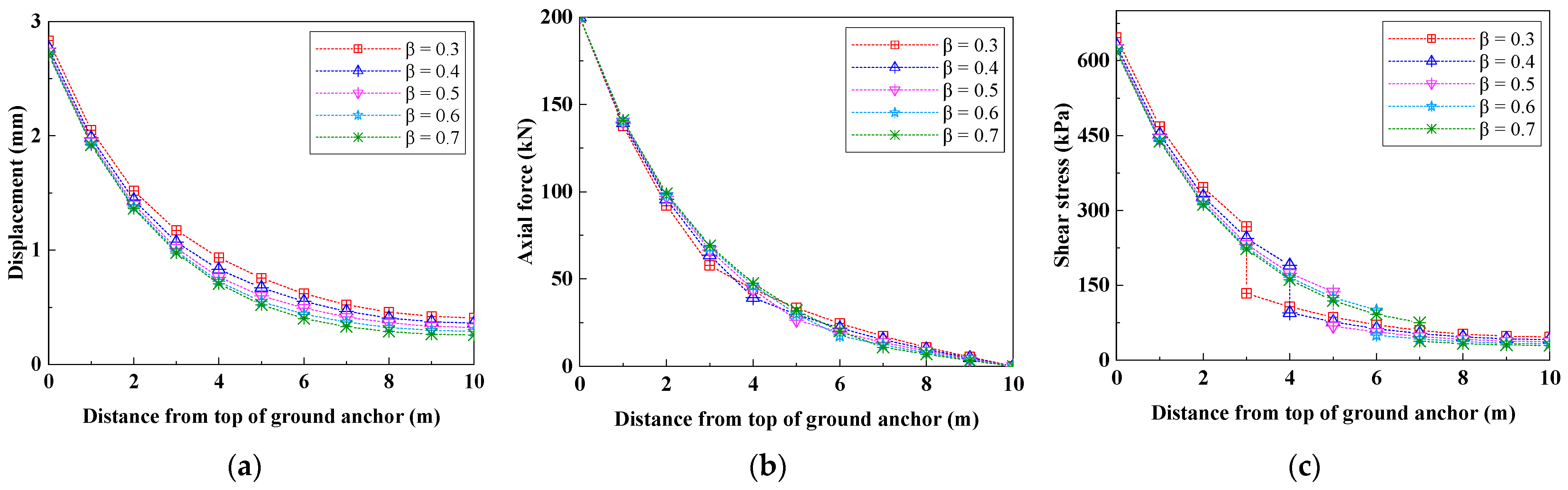
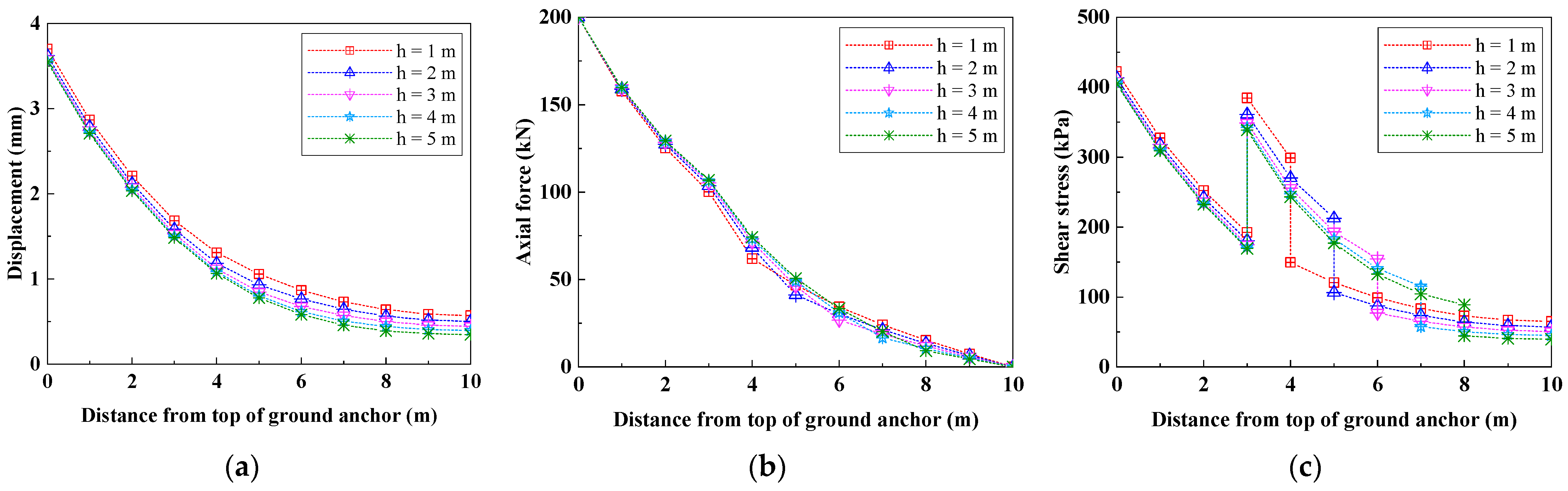
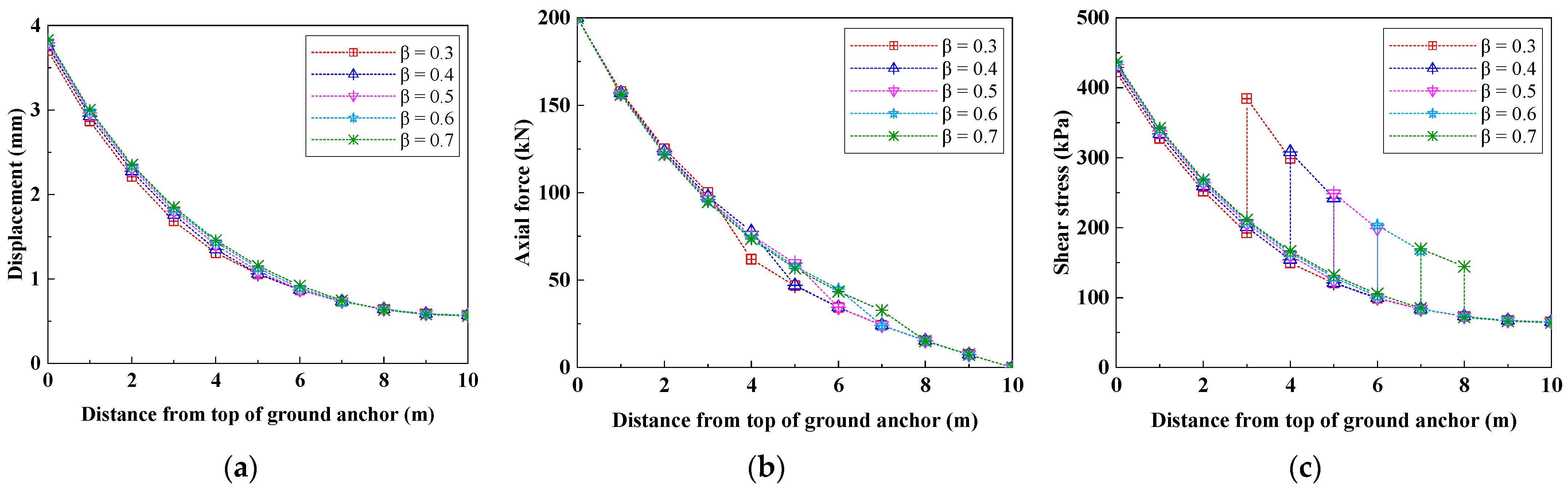
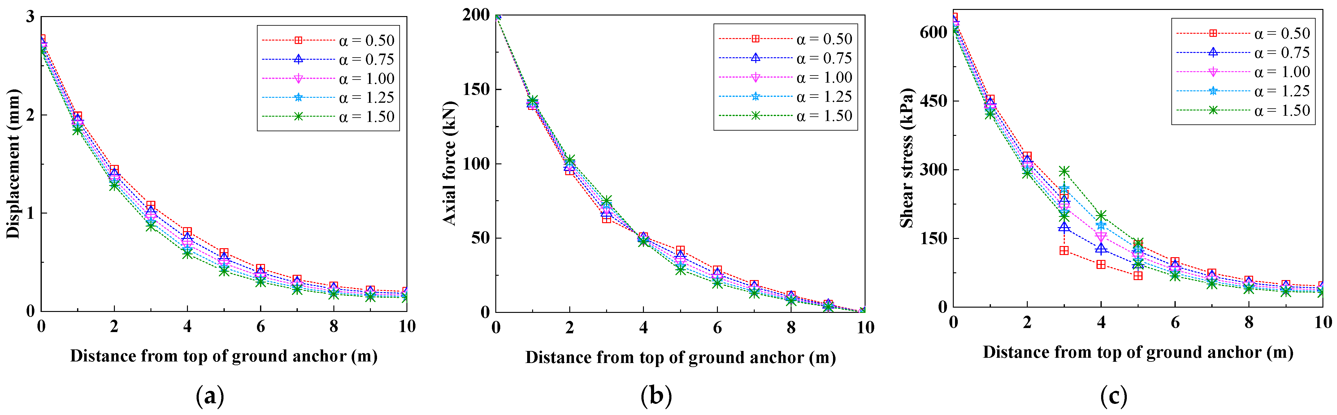
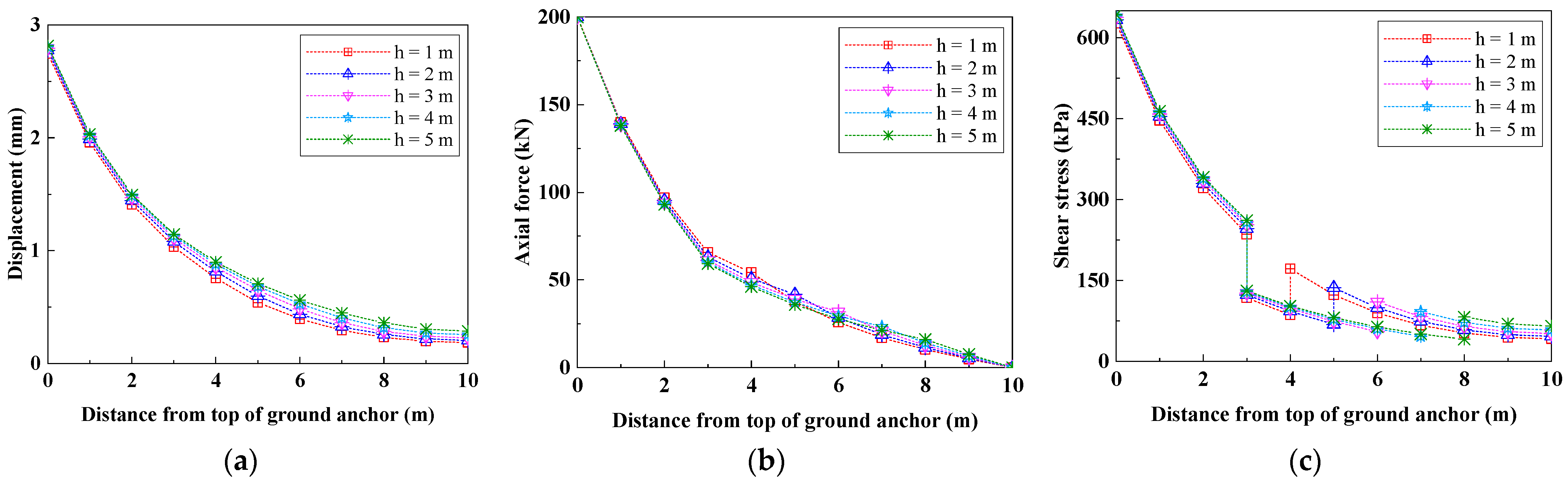
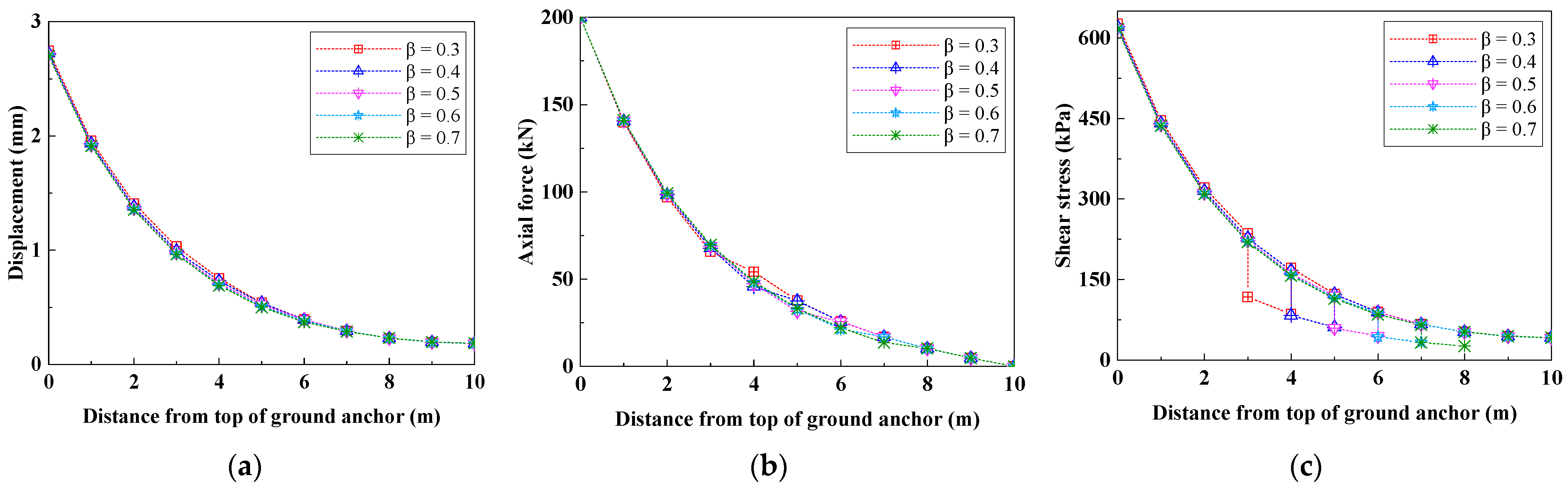
4.2. Case 2 (Corresponding to Stratum in Section 3.2)

Assume that the ground anchor is buried in the stratum as shown in Section 3.2, and discuss the influence of the change of stratum shear modulus, the thickness of interlayer, and the depth of stratum interface on the mechanical behavior of fully grouted ground anchor through several special conditions listed in Table 2.
Figure 10 shows the influence of the change of Gr1 on the mechanical behavior of the ground anchor under condition 1. It can be seen from Figure 10a that with the increase of Gr1, the displacement at each depth of the ground anchor is gradually decreasing. It can be seen from Figure 10b that, except for the top and tail of the ground anchor, the axial force at each depth of the ground anchor is gradually reduced with the increase of Gr1, and the axial force of the ground anchor in Stratum-2 decreases more obviously. It can be seen from Figure 10c that with the increase of Gr1, the shear stress at each depth of the ground anchor shows the following change trend: it gradually increases in Stratum-1 (upper layer), and the increase at the top of the ground anchor is more obvious; it decreases gradually in Stratum-1 (lower layer), and is slightly obvious at the tail of anchor rod; and it is also gradually decreasing in Stratum-2.
Figure 11 shows the influence of the change of h on the mechanical behavior of the ground anchor under condition 2. It can be seen from Figure 11a that with the increase of h, the displacement at each depth of the ground anchor is slightly reduced, which is more obvious in the middle and lower part of the ground anchor. It can be seen from Figure 11b that with the increase of h, the axial force at the upper part of the ground anchor is slightly increased, whereas the axial force at the lower part of the ground anchor is slightly decreased, but both are not very obvious. It can be seen from Figure 11c that with the increase of h, the shear stress at each depth of ground anchor in Stratum-1 and Stratum-2 is gradually decreasing.
Figure 12 shows the influence of the change of xj1 on the mechanical behavior of the ground anchor under condition 3. It can be seen from Figure 12a that with the increase of xj1, the displacement at each depth in the middle and upper part of the ground anchor is slightly increased, whereas there is almost no change at the lower part of the ground anchor. It can be seen from Figure 12b that with the increase of xj1, the axial force of the ground anchor in Stratum-2 is gradually reduced, whereas there is almost no change in Stratum-1. It can be seen from Figure 12c that with the increase of xj1, the shear stress at each depth of the ground anchor increases slightly in Stratum-1 (upper layer), decreases gradually in Stratum-2, and has almost no change in Stratum-1 (lower layer).
Figure 13 shows the influence of the change of Gr2 on the mechanical behavior of the ground anchor under condition 4. It can be seen from Figure 13a that with the increase of Gr2, the displacement at each depth of the ground anchor decreases slightly. It can be seen from Figure 13b that with the increase of Gr2, the axial force at the upper part of the ground anchor is slightly increased, whereas the axial force at the lower part is slightly reduced. It can be seen from Figure 13c that with the increase of Gr2, the shear stress at each depth of the ground anchor decreases slightly in Stratum-1, but increases gradually in Stratum-2.
Figure 14 shows the influence of the change of h on the mechanical behavior of the ground anchor under condition 5. It can be seen from Figure 14a that with the increase of h, the displacement at each depth of the ground anchor increases slightly. It can be seen from Figure 14b that with the increase of h, the axial force at the upper part of the ground anchor is slightly reduced, whereas the axial force at the lower part of the ground anchor is slightly increased, but both are not very obvious. It can be seen from Figure 14c that with the increase of h, the shear stress at each depth of the ground anchor in Stratum-1 and Stratum-2 increases slightly.
Figure 15 shows the influence of the change of xj1 on the mechanical behavior of the ground anchor under condition 6. It can be seen from Figure 15a,b that with the increase of xj1, the displacement and axial force at each depth of the ground anchor change little, and almost no change can be seen. It can be seen from Figure 15c that with the increase of xj1, the shear stress at each depth of the ground anchor has almost no change in Stratum-1, but gradually decreases in Stratum-2.
It can be seen from the comprehensive comparison of Figure 10, Figure 11, Figure 12, Figure 13, Figure 14 and Figure 15 that the change of shear modulus of Stratum-1 has a great impact on the mechanical behavior of the ground anchor. To be exact, it is the change of the shear modulus of the shallow part of the ground anchor that has a great impact on the mechanical behavior of the ground anchor. The change of shear modulus of Stratum-2 has a certain impact on the mechanical behavior of the ground anchor in Stratum-2, but the impact is not particularly great and has little impact on the mechanical behavior of the ground anchor in Stratum-1. Whether it is a soft interlayer or hard interlayer, the change of interlayer thickness and depth has a certain impact on the mechanical behavior of the ground anchor, but the influence on the displacement and axial force distribution of the ground anchor is relatively weak.

5. Conclusions

In this paper, it is assumed that the ground anchor and the rock–soil are connected by tangential linear springs, and the analytical solution of the mechanical behavior of the ground anchor buried in the upper and lower parallel strata foundation and the sandwich foundation is derived by using the spring element method, respectively. Corresponding to the above two kinds of alternating strata, the mechanical behavior of the vertical fully grouted ground anchor in the soft–hard alternating stratum was analyzed by using the four conditions in Case 1 and the six conditions in Case 2, respectively.
Through the case analysis, the following conclusions are drawn: the change of the shear modulus of the shallow stratum has a great impact on the mechanical behavior of the whole ground anchor; the change of the shear modulus of the deep stratum has little effect on the whole anchor; the changes of the depth of the stratum interface and the thickness of the interlayer have a certain influence on the anchor, but have relatively weak effects on the displacement and axial force distribution of the ground anchor.

6. Discussion and Prospect

In fact, the analysis results of the spring element method are identical to those of the traditional load transfer method, but different models are shown in the derivation process. Compared with the traditional load transfer method, the spring element method is intuitive, simple, and easy to understand. In addition, another obvious advantage of this method is that it can combine the stiffness of the anchor and the stiffness of the sidewall for analysis, so as to extract the key parameters λ. Parameter λ is the square root of the ratio of the stiffness of the sidewall to the stiffness of the anchor. Through analysis λ, it can reflect the influence of stratum shear modulus on the bearing characteristics of anchors. In addition, it should be noted that in this paper, we have not used the proposed model to simulate the ultimate pullout force of the ground anchor, nor compared the analysis results of our model with other analysis models or test data, because the purpose of this paper is to analyze the influence of the difference between the shear models of the soft–hard alternating stratum on the mechanical behavior of ground anchor from the perspective of theoretical analysis. It is also limited to the elastic deformation stage, that is, the ground anchor is not debonded. If the ground anchor does not debond, the ultimate pullout force cannot be analyzed. In the subsequent research work, we will further carry out the research on the ultimate pullout force of fully grouted ground anchors in the soft and hard alternating strata on the basis of this study.

Author Contributions

Conceptualization, X.L.; methodology, X.L.; software, X.L.; validation, X.L. and Z.M.; formal analysis, X.L. and Z.M.; investigation, X.L. and Z.M.; resources, X.L. and Z.M.; data curation, X.L. and Z.M.; writing—original draft preparation, X.L.; writing—review and editing, X.L.; visualization, X.L.; supervision, Z.M.; project administration, Z.M. All authors have read and agreed to the published version of the manuscript.

Funding

This research received no external funding.

Data Availability Statement

The manuscript data used to support the findings of this study are available from the corresponding author upon request.

Conflicts of Interest

The authors declare no conflict of interest.

References

  1. Ren, F.F.; Yang, Z.J.; Chen, J.F.; Chen, W.W. An analytical analysis of the full-range behaviour of grouted rock bolts based on a tri-linear bond-slip mode1. Constr. Build. Mater. 2010, 24, 361–370. [Google Scholar] [CrossRef]
  2. Zou, J.F.; Zhang, P.H. Analytical model of fully grouted bolts in pull-out tests and in situ rock masses. Int. J. Rock Mech. Min. Sci. 2019, 113, 278–294. [Google Scholar] [CrossRef]
  3. Ma, S.; Nemcik, J.; Aziz, N. An analytical model of fully grouted rock bolts subjected to tensile load. Constr. Build. Mater. 2013, 49, 519–526. [Google Scholar] [CrossRef]
  4. Fujita, K. A method to predict the load-displacement relationship of ground anchors. In Proceedings of the 9th International Conference on Soil Mechanics and Foundation Engineering, Tokyo, Japan, 10–15 July 1977. [Google Scholar]
  5. Stillborg, B. Experimental Investigation of Steel Cables for Rock Reinforcement in Hard Rock. Ph.D. Thesis, Lulea University of Technology, Luleå, Sweden, 1984. [Google Scholar]
  6. Su, W.; Fragaszy, R.J. Uplift testing of model anchors. J. Geotech. Eng. Div. 1988, 114, 961–983. [Google Scholar] [CrossRef]
  7. Hyett, A.J.; Bawden, W.F.; Relchert, R.D. The effect of rock mass confinement on the bond strength of fully grouted cable bolts. Int. J. Rock Mech. Min. Sci. Geomech. Abstr. 1992, 29, 503–524. [Google Scholar] [CrossRef]
  8. Kilic, A.; Yasar, E.; Celik, A.G. Effect of grout properties on the pull-out load capacity of fully grouted rock bolt. Tunn. Undergr. Space Technol. 2002, 17, 355–362. [Google Scholar] [CrossRef]
  9. Kim, N.K. Performance of tension and compression anchors in weathered soil. J. Geotech. Geoenviron. Eng. 2003, 129, 1138–1150. [Google Scholar] [CrossRef]
  10. Huang, M.H.; Zhou, Z.; Huang, Y.; Ou, J.P. A distributed self-sensing FRP anchor with built-in optical fiber sensor. Measurement 2013, 46, 1363–1370. [Google Scholar] [CrossRef]
  11. Phillips, S.H.E. Factors Affecting the Design of Anchorages in Rock; Cementation Research Ltd.: London, UK, 1970. [Google Scholar]
  12. Farmer, I.W. Stress distribution along a resin grouted rock anchor. Int. J. Rock Mech. Min. Sci. Geomech. Abstr. 1975, 12, 347–351. [Google Scholar] [CrossRef]
  13. Wijk, G. A theoretical remark on the stress field around prestressed rock bolts. Int. J. Rock Mech. Min. Sci. Geomech. Abstr. 1978, 15, 289–294. [Google Scholar] [CrossRef]
  14. Aydan, O.; Ichikawa, Y.; Kawamoto, T. Load bearing capacity and stress distributions in along rock bolts with inelastic behaviour of interfaces. In Proceedings of the 5th International Conference on Numerical Methods in Geomechanics, Nagoya, Japan, 1–5 April 1985. [Google Scholar]
  15. Li, C.; Stillborg, B. Analytical models for rock bolts. Int. J. Rock Mech. Min. Sci. 1999, 36, 1013–1029. [Google Scholar] [CrossRef]
  16. Chen, J.; Saydam, S.; Hagan, P. An analytical model of the load transfer behavior of fully grouted cable bolts. Constr. Build. Mater. 2015, 101, 1006–1015. [Google Scholar] [CrossRef]
  17. Li, D.; Cai, M.; Masoumi, H. A constitutive model for modified cable bolts exhibiting cone shaped failure mode. Int. J. Rock Mech. Min. Sci. 2021, 145, 104855. [Google Scholar] [CrossRef]
  18. Jahangir, E.; Blanco-Martín, L.; Hadj-Hassen, F.; Tijani, M. Development and application of an interface constitutive model for fully grouted rock-bolts and cable-bolts. J. Rock Mech. Geotech. Eng. 2021, 13, 811–819. [Google Scholar] [CrossRef]
  19. Guo, P.P.; Gong, X.N.; Wei, Z.Y. A pullout mechanical model for tension-type ground anchor penetrating two soil stratums and its application. China J. Highw. Transp. 2022, 35, 1–10. [Google Scholar]
  20. Liu, X.; Ma, Z. Mechanical behavior analysis of fully grouted bolts under axial cyclic load. Minerals 2022, 12, 1566. [Google Scholar] [CrossRef]
  21. Malvar, L.J. Bond reinforcement under controlled confinement. ACI Mater. J. 1992, 89, 593–601. [Google Scholar]
  22. Moosavi, M.; Khosravi, A.; Jafari, A. A laboratory study of bond failure mechanism in deformed rock bolts using a modified Hoek cell. In Proceedings of the 2001 ISRM International Symposium-Second Asian Rock Mechanics Symposium (ISRM 2001-2nd ARMS), Beijing, China, 11–14 September 2001. [Google Scholar]
  23. Cai, Y.; Esakia, T.; Jiang, Y.J. A rock bolt and rock mass interaction model. Int. J. Rock Mech. Min. Sci. Geomech. Abstr. 2004, 41, 1055–1067. [Google Scholar] [CrossRef]
Figure 1. Schematic diagram of discretization of free rod.
Minerals 13 00059 g001
Figure 2. Schematic diagram of discretization of anchor.
Minerals 13 00059 g002
Figure 3. Force analysis diagram of the ith spring element.
Minerals 13 00059 g003
Figure 4. Ground anchors buried in upper and lower parallel strata foundation.
Minerals 13 00059 g004
Figure 5. Ground anchors buried in sandwich foundation.
Minerals 13 00059 g005
Figure 6. Effect of shear modulus change of Stratum-1 on mechanical behavior of ground anchor. (Case 1: condition 1) (a) displacement distribution curve; (b) axial force distribution curve; (c) shear stress distribution curve.
Minerals 13 00059 g006
Figure 7. Effect of the depth of stratum interface on mechanical behavior of ground anchor. (Case 1: condition 2) (a) displacement distribution curve; (b) axial force distribution curve; (c) shear stress distribution curve.
Minerals 13 00059 g007
Figure 8. Effect of shear modulus change of Stratum-2 on mechanical behavior of ground anchor. (Case 1: condition 3) (a) displacement distribution curve; (b) axial force distribution curve; (c) shear stress distribution curve.
Minerals 13 00059 g008
Figure 9. Effect of the depth of stratum interface on mechanical behavior of ground anchor. (Case 1: condition 4) (a) displacement distribution curve; (b) axial force distribution curve; (c) shear stress distribution curve.
Minerals 13 00059 g009
Figure 10. Effect of shear modulus change of Stratum-1 on mechanical behavior of ground anchor. (Case 2: condition 1) (a) displacement distribution curve; (b) axial force distribution curve; (c) shear stress distribution curve.
Minerals 13 00059 g010
Figure 11. Effect of interlayer thickness change on mechanical behavior of ground anchor. (Case 2: condition 2) (a) displacement distribution curve; (b) axial force distribution curve; (c) shear stress distribution curve.
Minerals 13 00059 g011
Figure 12. Effect of the depth of stratum interface on mechanical behavior of ground anchor. (Case 2: condition 3) (a) displacement distribution curve; (b) axial force distribution curve; (c) shear stress distribution curve.
Minerals 13 00059 g012
Figure 13. Effect of shear modulus change of Stratum-2 on mechanical behavior of ground anchor. (Case 2: condition 4) (a) displacement distribution curve; (b) axial force distribution curve; (c) shear stress distribution curve.
Minerals 13 00059 g013
Figure 14. Effect of interlayer thickness change on mechanical behavior of ground anchor. (Case 2: condition 5) (a) displacement distribution curve; (b) axial force distribution curve; (c) shear stress distribution curve.
Minerals 13 00059 g014
Figure 15. Effect of the depth of stratum interface on mechanical behavior of ground anchor. (Case 2: condition 6) (a) displacement distribution curve; (b) axial force distribution curve; (c) shear stress distribution curve.
Minerals 13 00059 g015
Table 1. Several special conditions in Case 1.
ConditionsShear Modulus of Stratum-1
Gr1 (MPa)
Shear Modulus of Stratum-2
Gr2 (MPa)
Depth of Stratum Interface
xj (m)
Condition 1α·Gr2805
Condition 24080β·l
Condition 380α·Gr15
Condition 48040β·l
Note: In the table α and β are the variation coefficients.
Table 2. Several special conditions in Case 2.
ConditionsShear Modulus of
Stratum-1
Gr1 (MPa)
Shear Modulus of
Stratum-2
Gr2 (MPa)
Top Surface Depth of
Interlayer
xj1 (m)
Thickness of
Interlayer
h (m)
Condition 1α·Gr28032
Condition 240803h
Condition 34080β·l1
Condition 480α·Gr132
Condition 580403h
Condition 68040β·l1
Disclaimer/Publisher’s Note: The statements, opinions and data contained in all publications are solely those of the individual author(s) and contributor(s) and not of MDPI and/or the editor(s). MDPI and/or the editor(s) disclaim responsibility for any injury to people or property resulting from any ideas, methods, instructions or products referred to in the content.

