Article

Spatial Distribution Characteristics of Plastic Failure and Grouting Diffusion within Deep Roadway Surrounding Rock under Three-Dimensional Unequal Ground Stress and Its Application

1
College of Sciences, Xi’an University of Science and Technology, Xi’an 710054, China
2
College of Energy Engineering, Xi’an University of Science and Technology, Xi’an 710054, China
*
Author to whom correspondence should be addressed.
Minerals 2022, 12(3), 296; https://doi.org/10.3390/min12030296
Submission received: 11 January 2022 / Revised: 22 February 2022 / Accepted: 24 February 2022 / Published: 26 February 2022
(This article belongs to the Topic Support Theory and Technology of Geotechnical Engineering)

Abstract

:
To explore the bolt-grouting method of the deep roadway under three-dimensional unequal ground stress, a unidirectional coupling model of surrounding rock plastic failure and grouting diffusion considering the influence of excavation disturbance stress was established. Spatial evolution characteristics of plastic failure and grouting diffusion, and the impact of the spacing and row spacing of grouting bolts/cables on grout diffusion, were simulated by using the numerical method. The results revealed that the horizontal ground stress perpendicular to the axial direction of the roadway was the main factor inducing roadway damage. Moreover, the more significant the difference of the ground stress in three directions, the larger the plastic zone of the roof corner and floor corner of the roadway. Under different lateral pressure coefficients, the grout diffused can be approximate ellipsoid and cylinders. Furthermore, the larger the ratio of lateral pressure coefficients perpendicular to and parallel to the axial direction of roadway, the larger the diffusion length of grout in each spatial direction in the surrounding rock. In bolt-grouting support, the length of the grouting bolts/cables should be greater than the plastic zone of the surrounding rock, and the optimal relationship between their spacing and row spacing and diffusion length of grout is determined. The research results were applied in the bolt-grouting engineering for the three-level main roadway in the Haizi Coal Mine, and a good support effect was achieved. This can provide technical guidance and a method of reference for the design and parameter optimization of bolt-grouting support for roadways under deep high ground stress.

1. Introduction

The demand for mineral resources has been increasing with the rapid growth of the world economy, and shallow mineral resources are gradually depleted. Thus, coal mining is slowly extending to the deep [1,2,3,4,5], resulting in a more complex geological environment and geological structure of rock strata [6,7]. Under the effect of high ground stress and strong mining disturbance [8,9], the soft and broken surrounding rock of roadways increases gradually, which leads to the difficulty of supporting control [10]. Therefore, it is necessary to improve the stability of roadways [11,12]. Zhang et al. [13,14] studied the stability of a dual circular tunnel and unlined rectangular tunnel under surcharge load, providing a basis for the stability control of a tunnel. Shi [15] and Kumar [16] et al. improved the stability of roadway surrounding rock by studying bolts. Wang et al. [17] used automatically formed roadway by roof cutting with bolt grouting to ensure the collapse of the overlying strata. As an effective supporting method, bolt-grouting support technology [18,19] can improve the integrity and load-bearing capacity of the fractured rock mass, thereby improving the stability of the deeply fractured roadway surrounding rock. Nevertheless, many factors affect the effect of grouting reinforcement of the fractured roadway surrounding rock, such as the ground stress environment, surrounding rock failure characteristics, grout diffusion length, and grouting design. Hence, it is necessary to study in depth.
Aiming at the problem of the effect of ground stress on the failure of roadway surrounding rock, Ma et al. [20] derived the calculation formula of the deviatoric stress field and plastic failure range of circular roadways under non-uniform stress by elastoplastic mechanics. Guo et al. [21] further obtained the key factors affecting the plastic failure characteristics of roadway surrounding rock. Based on this, Shang and Zhang [22] obtained the analytical formulas of stress in the elastic, plastic, and damage zones around the circular wellbore by using the ground stress decomposition method and analyzed the influence of non-uniform ground stress on the range of the plastic zone. Yu et al. [23] investigated the failure characteristics of different types of roadways by establishing the constitutive equation of deviatoric stress field and plastic zone distribution. Furthermore, they put forward targeted control measures. Huang et al. [24] obtained the theoretical solution of stress and plastic fracture range after the simplified circular roadway model and combined it with numerical simulation methods to reveal the impact of the lateral pressure coefficient on the internal stress field and plastic area of the surrounding rock. However, the above mainly focused on elasticity and plasticity and did not analyze the characteristics of the fractured zone after plastic yielding. To this point, Wang et al. [25] analyzed the failure characteristics of the surrounding rock and plastic fracture zones of the circular roadway under asymmetric stress through numerical simulation and theoretical calculation. Wang et al. [26] investigated the influence of the lateral pressure coefficient and principal stress direction on the failure of the roadway. These studies provide the theoretical basis for analyzing the effect of ground stress on plastic damage characteristics of tunnels. However, most of these studies simply considered the roadway surrounding rock as a plane strain problem, that is, ignoring the influence of axial stress [27], while the actual surrounding rock of a roadway is a triaxial stress state [28,29], resulting in significant differences between the deformation and damage of surrounding rock and the actual situation. Therefore, Zheng et al. [30] derived the analytical solution of elastic and plastic stress and the calculation formula of the plastic damage range of roadway floor surrounding rock under three-dimensional ground stress. Huang et al. [31] obtained the stress field and plastic failure characteristics of the circular roadway under three-dimensional ground stress using the finite difference numerical method. However, this study did not consider the influence of non-circular roadways on the plastic failure of surrounding rock and ignored the effect of the horizontal lateral pressure coefficient in different directions on the overall failure characteristics of the surrounding rock. Therefore, it is necessary to study further the spatial distribution characteristics of plastic failure of the roadway under three-dimensional unequal ground stress to better guide the grouting support design of fractured surrounding rock.
Scholars have achieved fruitful research results regarding another key factor affecting the effect of grouting reinforcement—the grouting diffusion law. Huang et al. [32] obtained the influence of grouting parameters such as grouting pressure, time, and bolt arrangement on grouting diffusion and reinforcement effect. Liu et al. [33] investigated the influence factors of grouting diffusion length using a discrete fracture network model. Geng et al. [34] used PFC2D to simulate the dynamic process of grouting diffusion under different pressures to study the grouting effect under different grouting pressures and grouting hole layout and provided a reference for optimizing the grouting scheme. Yang et al. [35] investigated the effects of flow velocity, grouting pressure, and joint roughness on slurry diffusion length by establishing experiments of different roughness and flowing water environments. Zhou et al. [36] established a theoretical model of slurry diffusion and analyzed the influence of grouting parameters such as viscosity coefficient, rheological index, grouting time, and fracture height on the grouting pressure difference and diffusion radius, which can provide the theoretical basis for grouting design. Zhang et al. [37] derived the governing equation of fracture grouting based on the conservation of mass, radial flow pattern, and time-varying viscosity of grout, and discussed the influence of grouting pressure and cracked width on the permeation diffusion range. Liu and Sun [2,38,39] established a plane model of grouting diffusion through the combination of finite elements and discrete elements and obtained the grouting diffusion law when horizontal ground stress was equal. However, they did not study the influence of horizontal ground stress on grouting diffusion. These research results lay a foundation for understanding the diffusion law of grout in the fractured surrounding rock and provide a reference method for systematic and in-depth study of this problem. However, the above study did not consider the influence of three-dimensional unequal ground stress and excavation disturbance on grout diffusion and did not correlate it with the three-dimensional fracture characteristics of surrounding rock. Therefore, it could not effectively and optimally guide the grouting reinforcement engineering practice.
Based on existing research results, we used the Mohr–Coulomb strength criterion and Darcy’s flow to construct a unidirectional coupling model of surrounding rock plastic failure and grouting diffusion. The finite element method was adopted to investigate the influence of three-dimensional ground stress on the spatial distribution characteristics of plastic failure of surrounding rock and grout diffusion, and the influence of grouting bolt/cable spacing and row spacing distance on grout diffusion. Finally, according to the numerical analysis results, a bolt-grouting support parameter optimization method was proposed based on the failure characteristics of surrounding rock and the diffusion length of grout. The method was applied to the engineering practice of bolt-grouting support in deep soft rock roadway with high ground stress, and the supporting effect was verified numerically and monitored on-site.

2. Unidirectional Coupling Model of Plastic Failure and Grouting Diffusion in Surrounding Rock

2.1. Unidirectional Coupling Theory of Plastic Failure and Grouting Diffusion

To keep a stable balance in the deep roadway under the combined action of gravity and ground stress, the index sign form of the equilibrium equation that should be satisfied is [40]:
σ j i , j + f j = 0
where σ is the stress of the rock (Pa), f is the volume force of the rock, and i and j are the index symbols, indicating the spatial coordinate system.
During stress redistribution in surrounding rock after roadway excavation, the surrounding rock may be plastically broken, assuming that the failure satisfies the Mohr–Coulomb strength criterion, namely:
σ 1 1 + sin φ 1 sin φ σ 3 2 c cos φ 1 sin φ σ 3 = 0
where σ1 and σ3 are the principal stresses of rock (Pa), φ is the rock internal friction angle (°), and c is the cohesive of rock (Pa).
The roadway surrounding rock will deform after being stressed, which is usually measured by the strain of rock. The relationship between the deformation and the displacement of rock is [40]:
ε i j = ε j i = 1 2 ( u i , j + u j , i )
where ε is the rock strain, and u is the rock displacement (m).
According to the generalized Hooke’s law, the stress–strain constitutive relation of the roadway surrounding rock should be:
σ i j = D i j k l ( ε k l ε k l P )
where D is the rock elastic matrix (Pa), and εp is the plastic strain of rock.
Thus, the simultaneous Equations (1)–(4), coupled with boundary conditions and initial conditions, can solve the stress field and plastic strain (i.e., plastic fracture). However, it is difficult to obtain the analytical solution of this problem, because the equations are differential equations, and the solution variables are numerous. The finite element numerical method provides convenience for solving such issues, so it is used to obtain the spatial evolution law of stress field and plastic failure of roadway surrounding rock under three-dimensional unequal ground stress.
During grouting reinforcement, based on the continuum equation and Darcy’s law, the differential control equation of permeability diffusion of grout in fractured surrounding rock is [32]:
2 ( K p ) x 2 + 2 ( K p ) y 2 + 2 ( K p ) z 2 = μ s p t
where K is the grout equivalent permeability coefficient (m/s), p is grouting pressure (Pa), μs = ρg(nα + β) is the grout storage coefficient (m−1), n is the porosity of surrounding rock, t is the grouting time (s), α is the compression coefficient of surrounding rock (Pa−1), and β is the grout compression coefficient (Pa−1).
For Equation (5), as long as we determine the equivalent permeability coefficient K and grout storage coefficient μs of fractured surrounding rock, the differential control equation of permeability diffusion of grout can be obtained by combining with suitable initial conditions and boundary conditions. However, considering grouting reinforcement is the process of grout migration to the fracture of the inner hole of the broken surrounding rock [33], the deformation and failure characteristics of the pore and fissure in the rock are different under different deformation and fracture conditions. This will mainly influence the equivalent permeability coefficient K of grout and then affect the grout diffusion length. In addition, since the deformation and plastic fracture of surrounding rock is directly related to the rock stress, to consider the influence of different ground stress states on the permeability diffusion of grout, according to the negative exponential relationship between the permeability coefficient and material stress obtained in reference [41], the equivalent permeability coefficient K of grout in fractured surrounding rock can be expressed as:
K = K 0 ( Δ σ , p ) = K 0 e a ( Δ σ p ) = K 0 e a ( σ m σ m 0 p )
where Δσ = σmσm0 is the disturbance stress of surrounding rock excavation (Pa), σm = (σ1+σ2+σ3)/3 is the average principal stress of surrounding rock after excavation (Pa), σm0 = (σ10+σ20+σ30)/3 is the average principal stress of surrounding rock before excavation (Pa), K0 is the initial permeability coefficient of surrounding rock (m/s), and a is the macroscopic test parameter.
The above Equations (5) and (6) are the differential control equations of grouting diffusion in deep roadway surrounding rock under the coupling effect of plastic fracture and grouting pressure. However, since the grouting pressure is much smaller than the stress of deep surrounding rock, this paper ignores the impact of grouting pressure on the surrounding rock fracture and focuses on the influence of the change of surrounding rock stress on the permeability diffusion of grout. Therefore, the surrounding rock plastic fracture and the permeability diffusion of grout are unidirectional couplings.

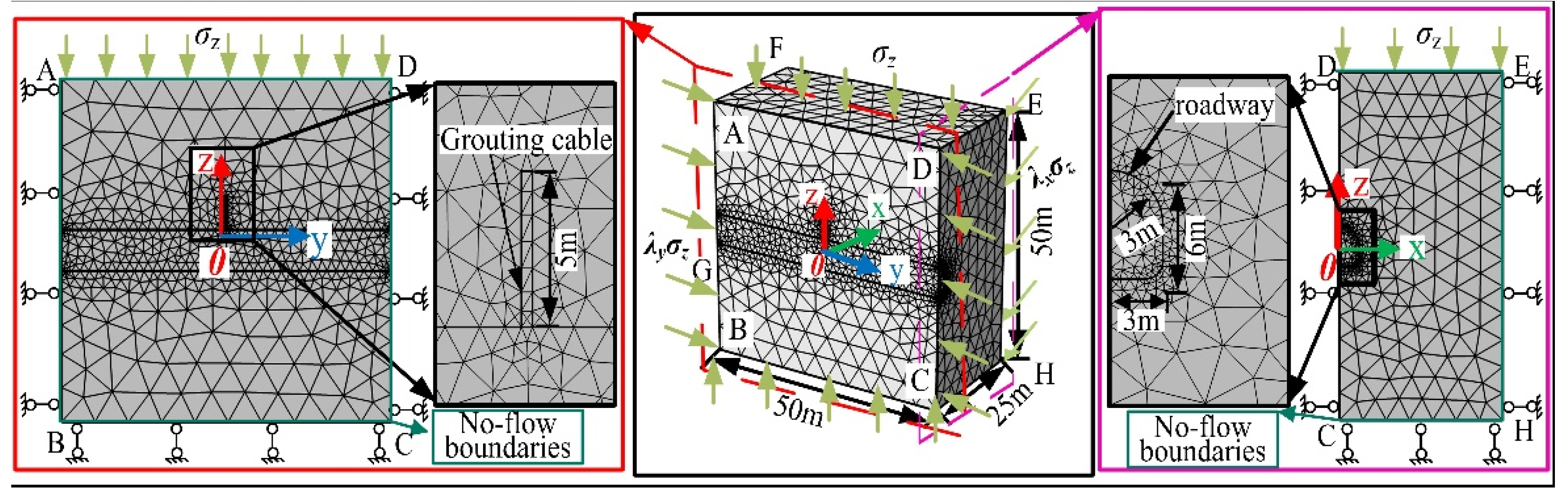
2.2. Unidirectional Coupling Numerical Model of Plastic Failure and Grouting Diffusion

It is challenging to obtain the analytical solution for the spatial problems of stress by Equations (1)–(6) of plastic fracture and grouting diffusion under the condition of three-dimensional ground stress. These equations cannot obtain the spatial evolution law of surrounding rock plastic fracture and grouting diffusion. Therefore, this paper studies the plastic fracture and grouting diffusion of surrounding rock by selecting the finite element numerical simulation method.
When the establishment of a finite element numerical model, it assumed that the roadway surrounding rock is a continuous medium, and the grout fills the whole grouting hole and maintains a constant grouting pressure p. This paper established the finite element numerical model by considering the symmetry of geometry and load, as shown in Figure 1. When the model is used to study the law of stress field and plastic fracture of surrounding rock, the surface FEHG, DEHC, AFGB, and BCHG of the model are all roller bearing constraints, and the surface ABCD is the symmetric boundary (see Figure 1). The upper boundary is the stress boundary σz = ρgh, which is the average weight of the overlying strata of the roadway. Initial stresses applied in x- and y-directions of the model σx = λxσz and σy = λyσz, respectively, where λx = 0.75, 1.0, 1.5, 2.0, 2.5, 3.0 and λy = 0.75, 1.0, 1.5, 2.0, 2.5, 3.0 are lateral pressure coefficients of horizontal x- and y-directions to simulate three-dimensional ground stress. The selection of the lateral pressure coefficient is based on references [24,42,43]. When the model is used to calculate the permeability diffusion law of grout, the grout cannot infinitely diffuse into the surrounding rock, so the model surfaces ADEF, BCHG, DEHC, AFGB, and FEHG are assumed to all be ideal no-flow boundaries. The model surface ABCD is still the symmetrical plane, and the surface of the grouting borehole is the initial grout pressure head H0 = p/γ, and γ is the unit weight of the grout (N·m−3), as shown in Figure 1. The relevant parameters of the surrounding rock and grout used are shown in Table 1.

2.3. Numerical Simulation Scheme

The deep surrounding rock is in an initial equilibrium state under three-dimensional unequal ground stress. Still, roadway excavation disturbance causes stress redistribution, resulting in the deformation and damage of surrounding rock. In turn, the increase of pores and cracks during the damage process will affect the deformation and strength of surrounding rock [44]. The pores and cracks in the fractured surrounding rock become the main channel of grouting diffusion, and then affect the permeability of grout [45]. The simulation adopts the following scheme to investigate the process of roadway surrounding rock from balance to failure and influence on grouting diffusion: First, the initial equilibrium of surrounding rock under three-dimensional unequal ground stress is simulated, to obtain the initial stress of surrounding rock. Second, the equilibrium state after roadway excavation is simulated, to obtain the spatial distribution characteristics of stress and surrounding rock plastic fracture after excavating. Finally, the change coupling of the stress field before and after roadway excavation is introduced into the equivalent permeability of grout to simulate the spatial distribution law of grouting diffusion.

2.4. Validation of Numerical Modeling Methods and Model

At present, due to the lack of a theoretical solution of the plastic zone range of a “horseshoe roadway”, especially in three-dimensional conditions, this paper refers to the theoretical solution of the plastic zone range of a circular roadway in reference [46], to verify the rationality of the numerical modeling methods and model. The theoretical solution of the plastic zone range is:
R = R 0 [ ( 1 + λ ) σ V + 2 ( 1 λ ) σ V cos 2 θ + 2 c cot φ ( 1 + B ) ( P i + c cot φ ) ] 1 A R 0
A = 4 ( 1 + b ) sin φ ( 2 + b ) ( 1 sin φ )
B = 2 + b + ( 2 + 3 b ) sin φ ( 2 + b ) ( 1 sin φ )
where R is the failure range of the plastic zone (m), R0 is roadway radius (m), θ is the horizontal angle with the center of roadway (°), b is the strength parameter of the unified strength theory, representing the influence degree of intermediate principal stress on the strength of geotechnical materials, Pi is support resistance (MPa), and the support resistance is 0 MPa.
When strength parameter b is 0, the effect of principal stress is ignored. Therefore, a two-dimensional numerical model of a circular roadway is established in this paper, and its numerical solution is obtained, as shown in Table 2. Meanwhile, the theoretical solution is obtained by using Equation (7), and the results are listed in Table 2. Comparing the theoretical and numerical solutions in Table 2, it is found that the relative errors in other parts of the roadway are less than 14% except that the relative error in the roadway ribs exceeds 30%. This shows that the method of applying the lateral pressure coefficient in numerical modeling is correct and reasonable.
Considering that the roadway shape and the modeling dimension will affect the plastic zone range, the numerical solution of the plastic zone range of a horseshoe roadway under three-dimensional stress and the theoretical solution of the plastic zone range of a circular roadway under two-dimensional stress considering the influence of intermediate principal stress (i.e., strength parameter b = 1) are given in Table 3. The comparison shows that there is an error difference between the numerical and theoretical solutions. This proves that the theoretical solution based on the plane theory cannot accurately predict the plastic failure range of the roadway, so it is necessary to carry out the three-dimensional numerical simulation study of the roadway failure.

3. Spatial Distribution Characteristics of Plastic Failure and Grouting Diffusion under Three-Dimensional Unequal Ground Stress

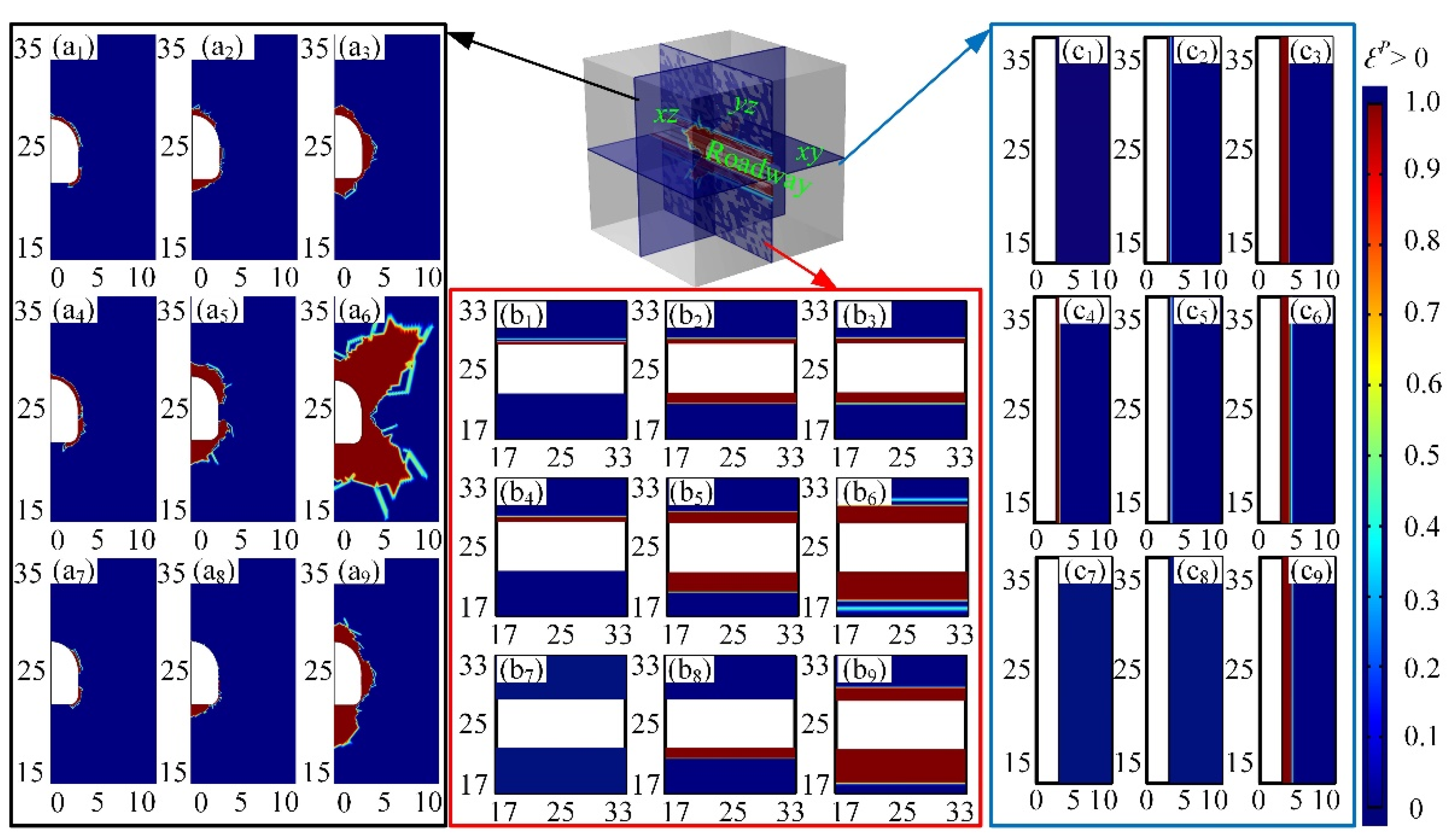
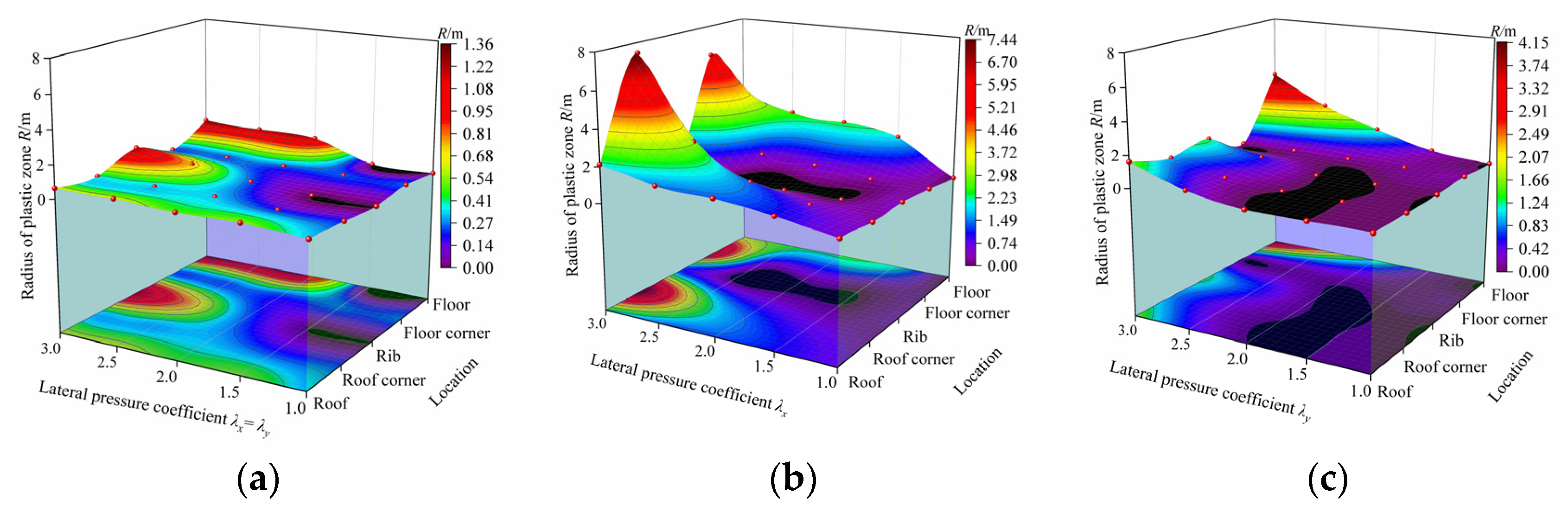
3.1. Spatial Distribution Characteristics of Plastic Failure

The simulated plastic failure of surrounding rock in three-dimensional space is given in Figure 2, to illustrate the spatial distribution characteristics of surrounding rock plastic damage under three-dimensional unequal ground stress. According to Figure 2(a1–a3,b1–b3,c1–c3), the plastic failure range of roadway surrounding rock increases with increasing lateral pressure coefficient when the horizontal lateral pressure coefficient λx = λy, but the range of plastic failure of surrounding rock at different positions is different. Figure 3a shows that the radius of the plastic zone in the roadway roof, right rib, and floor increases from 0.23 m, 0 m, and 0 m at λx = λy = 1 to 0.63 m, 1.23 m, and 1.35 m at λx = λy = 3. The results show that under the same horizontal ground stress, even if the horizontal ground stress is much larger than the vertical ground stress, the failure zone of the surrounding rock is also tiny as a whole.
However, when the horizontal lateral pressure coefficient λxλy, and λy remains unchanged at 0.75, an increase of λx, and the plastic failure zone in surrounding rock increases, as shown in Figure 2(a4–a6,b4–b6,c4–c6). Combined with Figure 3b, it can be observed that the plastic failure zones in the roof, roof corner, floor, and floor corner of the roadway increase from 0.54 m, 0.48 m, 0 m, and 0.36 m at λx = 1 to 2.12 m, 7.44 m, 3.44 m, and 6.28 m at λx = 3. In contrast, when the horizontal lateral pressure coefficient λx remains unchanged at 0.75, with the increase of λy, the change of the plastic failure zone in the surrounding rock is small except that the plastic failure zone in the floor of the roadway increases significantly (Figure 2(a7–a9,b7–b9,c7–c9)). When λx = 0.75, λy = 3, the maximum plastic zone of the floor is 2.38 m (Figure 3c), but it is far less than the maximum plastic zone of 7.44 m at λx = 3, λy = 0.75. The results show that the horizontal ground stress λx, which is perpendicular to the axial direction of the roadway, is the main factor to induce roadway failure under the condition of unequal ground stress in three directions. The larger λx is, that is, the more significant difference of ground stress in three directions, the greater the plastic zone in the roof corner and floor corner is, and the damage in the roof and floor is larger than that of the same horizontal ground stress. Therefore, we should focus on the roof corner, floor corner, roof, and floor of the broken roadway when grouting reinforcement is carried out under deep high ground stress.

3.2. Spatial Distribution Characteristics of Grouting Diffusion in the Surrounding Rock

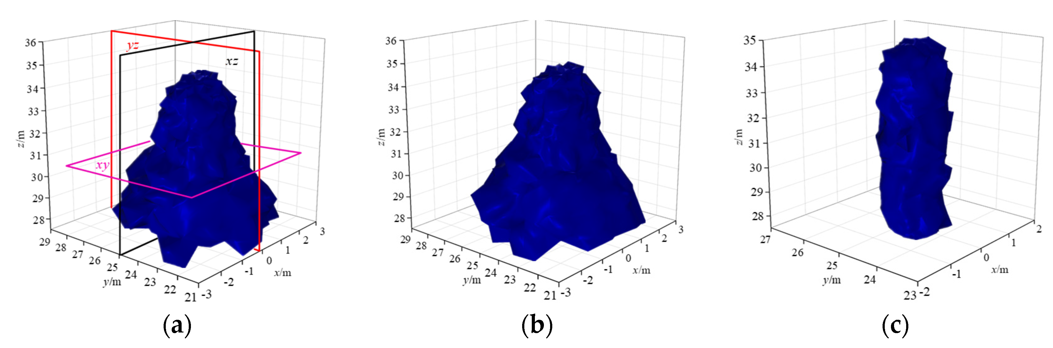
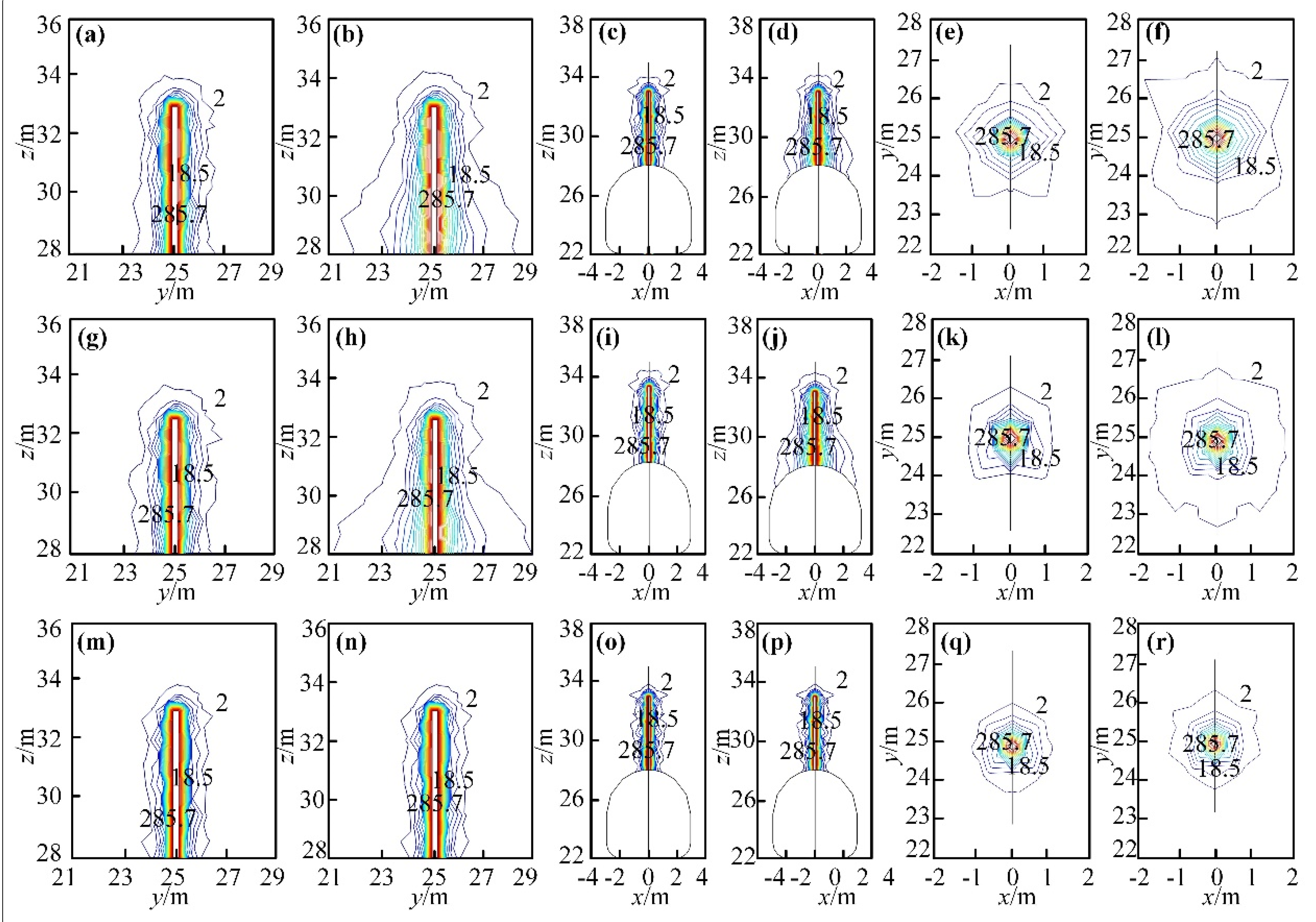
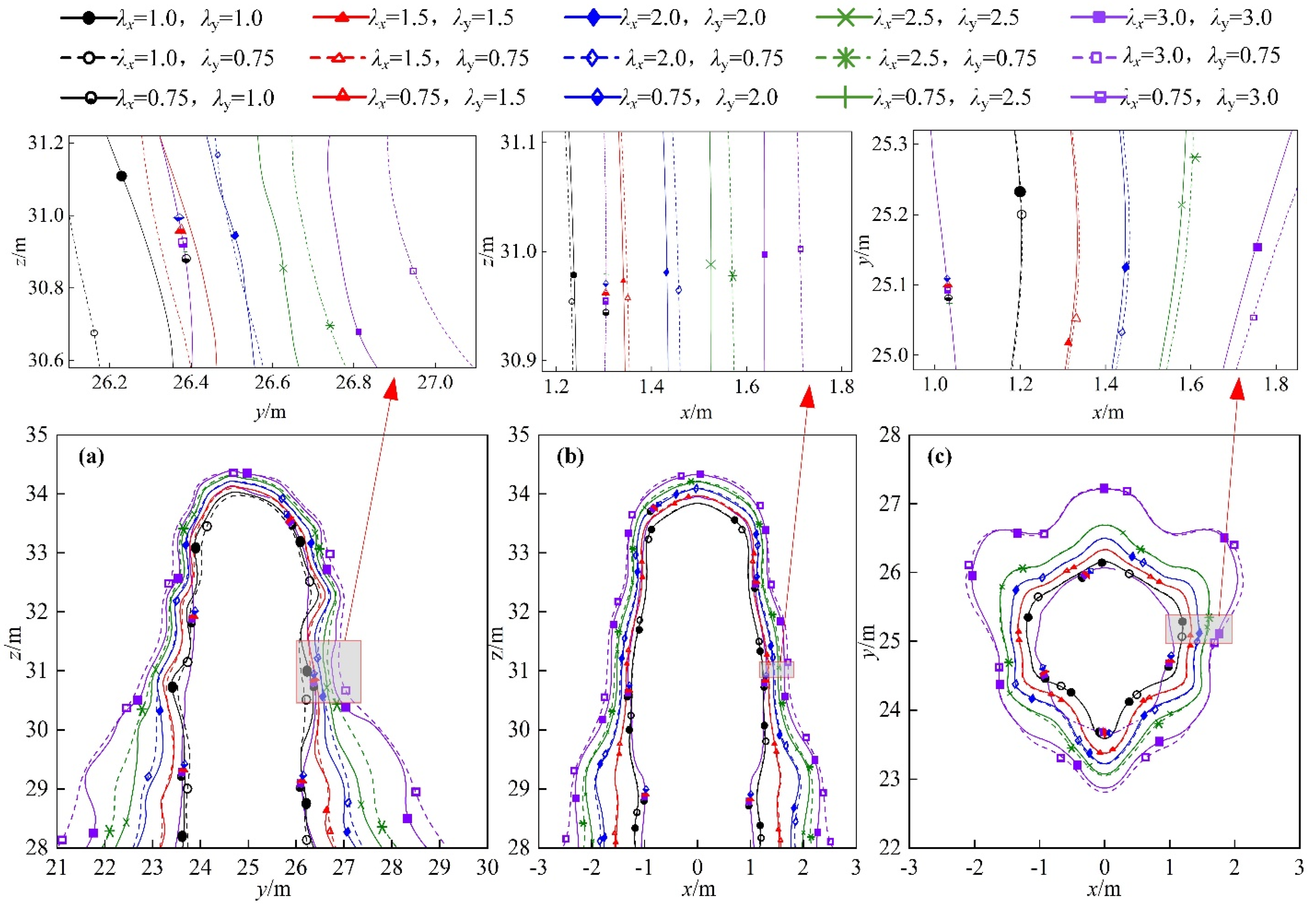
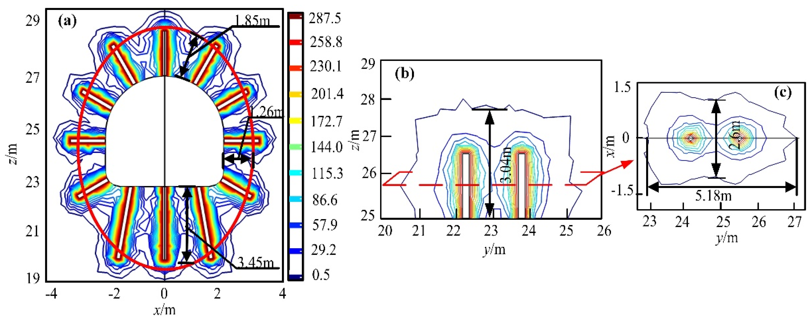
3.2.1. Diffusion Morphology of Grout

A grouting anchor cable with a diameter of 25 mm and a length of 5000 mm was arranged on the roadway roof to study the permeability diffusion law of grout in different spatial directions. The diffusion characteristics of grout in the surrounding rock were obtained by simulation, as shown in Figure 4. From Figure 4a,b, it can be found that when λx is greater than or equal to λy, the grout is generally cone-like after permeating and diffusing in the surrounding rock. This phenomenon is mainly due to the different damage degrees of surrounding rock to varying distances from the roadway surface, which makes the permeability of broken surrounding rock different and leads to the different diffusion lengths of grout. However, according to Figure 4c, when λx is less than λy, the plastic failure of surrounding rock to varying distances from the roadway surface is not obvious, so the grout is approximately cylindrical after permeating and diffusing in the surrounding rock.
In order to find out the diffusion pattern of grout in all directions of space in more detail, the lateral view (x = 0, yz plane), positive view (y = 25, xz plane), and overlooking view (z = 30.5, xy plane) of grouting diffusion in the surrounding rock of the roadway are given in Figure 5 according to three planes intercepted in Figure 4a. Figure 5 shows that under three-dimensional ground stress, the grout diffuses outward in the yz and xz plane with a grouting borehole as the center. However, the diffusion length in the direction parallel to the borehole is smaller, and the diffusion length in the direction perpendicular to the borehole is more significant, forming a quasi-elliptic distribution pattern, as shown in Figure 5a–d,g–i,m–p. The diffusion shape of grout in the xy plane is an approximate circle centered on the grouting borehole, as shown in Figure 5e–f,k–l,q–r.
By comparing Figure 5a–f, it can be found that when the horizontal lateral pressure coefficient λx = λy, with the increase of lateral pressure coefficient, permeability diffusion of grout in all directions of space in the fractured surrounding rock is greater. It is mainly due to that the greater the lateral pressure coefficient, the more serious the plastic failure of surrounding rock, and the more developed the pores and fractures in the surrounding rock, which promotes the penetration diffusion of the grout. However, at the horizontal lateral pressure coefficient λxλy, the greater the ratio of λx/λy, the greater the diffusion length of grout in all directions of the surrounding rock (Figure 5g–l), but when the ratio of λy/λx increases, the diffusion length of grout in all directions of the surrounding rock has no significant change (Figure 5m–r). This result occurs because the horizontal stress perpendicular to the axial direction of the roadway is the primary stress leading to the failure of the surrounding rock.

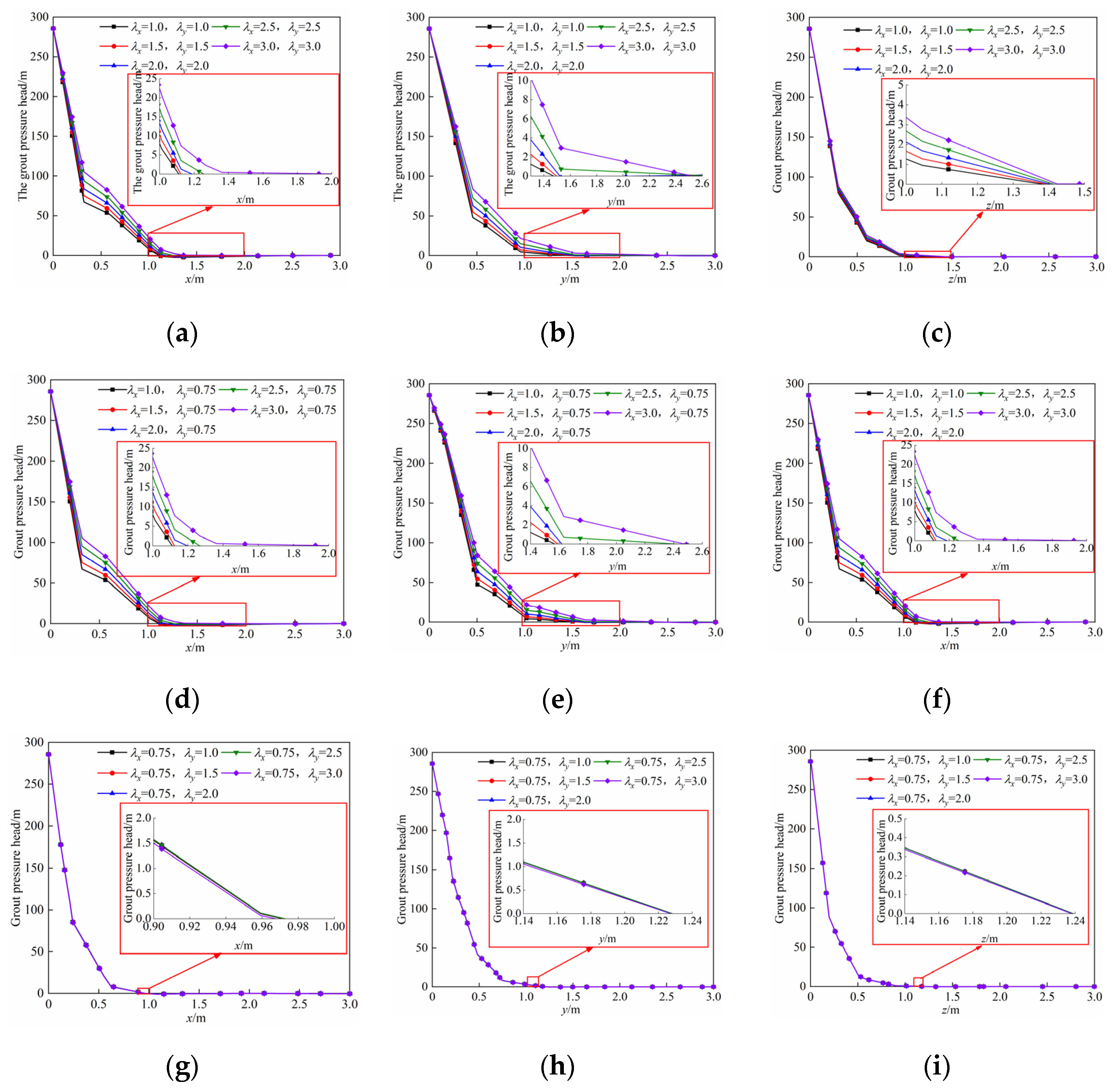
3.2.2. Attenuation Law and Diffusion Length of Grout Pressure Head

To further analyze the influence of horizontal ground stress in different directions on the diffusion length of grout, we drew the attenuation curve of the grout pressure head (intercepted 2.5 m away from the roadway according to Figure 6) and the diffusion length of grout under the different lateral pressure coefficients, as shown in Figure 7 and Figure 8, respectively. According to Figure 7 and Figure 8, the grout pressure head in each direction gradually decays with increasing the distance from the surface of the grouting borehole. However, the attenuation degree and diffusion length are different under different directions and lateral pressure coefficients.
The grout pressure head decays rapidly in x-, y-, and z-directions and then slowly decays to zero when the horizontal lateral pressure coefficient λx is equal to λy. The greater the lateral pressure coefficient, the farther the distance from the position where the grout pressure head attenuates to zero in the x- and y-directions to the surface of the grouting borehole, i.e., the greater the grouting diffusion length (Figure 7a,b). According to the schematic diagram of grouting diffusion range in Figure 6, the grouting diffusion length under each parameter is obtained, and the results are shown in Table 4. Combined with Figure 7 and Table 4, it can be found that at 2.5 m away from the roadway surface, the diffusion length of grout along with x- and y-directions increases from 1.25 m and 1.42 m when the horizontal lateral pressure coefficient λx = λy = 1.0 to 1.77 m and 2.29 m when λx = λy = 3.0, increasing by about 141.60% and 160.27%, respectively. However, in the z-direction (i.e., parallel to the borehole), the lateral pressure coefficient has little effect on the diffusion of grout (Figure 7c).
The attenuation law of the grout pressure head is similar to that of horizontal lateral pressure coefficient λx = λy when the horizontal lateral pressure coefficient λx > λy. Still, the diffusion length is different, as shown in Figure 7. As can be seen from Table 4, at 2.5 m away from the roadway surface, the diffusion length of grout along with x- and y-directions increases from 1.25 m and 1.43 m at the horizontal pressure coefficients λx = 1.0 and λy = 0.75 to 1.80 m and 2.29 m at λx = 3.0 and λy = 0.75, increasing by about 144% and 160.14%, respectively. However, when the horizontal lateral pressure coefficient λx < λy, with the increase of the lateral pressure coefficient, the attenuation of the grout pressure head has no obvious change (Figure 7g–i). It further shows that the horizontal ground stress λx perpendicular to the roadway axis is the primary control stress of the surrounding rock failure.
Moreover, as can be observed from Figure 8 and Table 4, the closer to the roadway surface, the greater the diffusion length of grout in all directions in space, i.e., the greater the diffusion length of grout in the shallow surrounding rock of the roadway. This result is mainly because the shallow surrounding rock is seriously damaged, therefore the pore-fracture is more developed. However, the deep surrounding rock is the opposite.

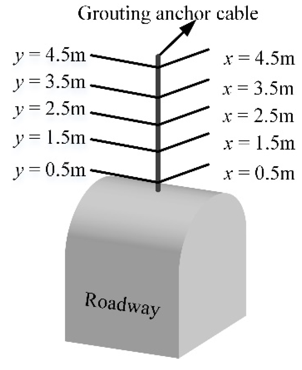
3.2.3. Optimization of Grouting Bolt/Cable Length and Spacing and Row Spacing Parameters

Considering that different ground stress will significantly affect the plastic failure characteristics of surrounding rock and the grouting diffusion characteristics, a reasonably arranged grouting bolt/cable is necessary. This can not only ensure the stability of the roadway but also avoid the waste of grouting bolt/cable and therefore save costs. Therefore, for optimizing the length and spacing and row spacing of grouting bolt/cable, the grouting diffusion law under different grouting bolt/cable lengths and spacing and row spacing is analyzed with the horizontal lateral pressure coefficient λx = 2, λy = 0.75 (the plastic zones in the roof, rib sides, floor are 1.37 m, 0 m, and 2.38 m, respectively, see Figure 3b) and grouting time of 1000 s.
Generally, the length of the grouting bolt is 1.6–3.0 m [47]. However, it must be considered that the failure of a deep roadway under high ground stress is more serious. Therefore, in this paper, a grouting bolt is used for support when the plastic failure zone is less than 3 m, and a grouting cable is used for support when the plastic failure zone is greater than 3 m. At the same time, to ensure the suspension effect of the grouting bolt/cable, the grouting bolt/cable length needs to exceed the plastic failure zone and be anchored to a relatively complete surrounding rock. Therefore, the grouting bolt/cable length designed in this paper is 0.5 m larger than the plastic zone.
According to the range of the plastic zone obtained above (see Figure 3), the length of the grouting bolt in the roof is designed to be 1.9 m, and the length of the grouting bolt in the floor is 2.9 m. To find out the reasonable spacing of grouting bolt/cable, the four layout schemes and grouting diffusion results are discussed, as shown in Figure 9. When the spacing of grouting bolts is 2.68 m, the grout diffusion between each grouting bolt is not sufficient, and the failure area cannot be completely filled to form an effective reinforcement ring, as shown in Figure 9a. When the spacing between grouting bolts is 1.79 m, the grout between grouting bolts can completely fill the plastic failure zone, and grouting reinforcement rings with thicknesses of 2.08 m, 1.6 m, and 3.30 m are formed in the roof, rib, and floor, respectively, as shown in Figure 9b. With the decrease of grouting bolt spacing, the thickness of the grouting reinforcement ring in the surrounding rock will increase slowly, but the increase is relatively small, and the number of grouting bolts will increase, which will lead to a rise in economic cost, as shown in Figure 9c,d. Therefore, considering the grouting reinforcement effect and economic cost, it is reasonable to choose the grouting bolt spacing of 1.79 m and 1.53 m (Figure 9b,c). In other words, when the spacing of the grouting bolt is 0.92–1.07 times the diffusion length of grout along the x-direction (i.e., in the cross-section of the roadway) at 1.5 m from the roadway surface, it is a reasonable arrangement.
Two grouting bolts in the roof are taken as the research object to study the influence of grouting bolt/cable row spacing on the grout diffusion law and grouting effect, and their row spacing arrangement form and diffusion effect are shown in Figure 10. Figure 10 shows that with the increase of row spacing, the diffusion length of grout in x- and z-directions gradually decreases. Specifically, the diffusion lengths of grout in x- and z-directions decreased from 2.84 m and 3.07 m (Figure 10a) at a row spacing of 2.0 m, to 1.52 m and 1.30 m (Figure 10d) at row spacing of 3.5 m, respectively, by about 57.65% and 46.48%. It indicates that the larger the row spacing, the grout cannot form an effective reinforcement body in the x- and z- direction, that is, the reinforcement effect is poor. Moreover, when the row spacing is large, the mutual penetration diffusion of grout between grouting bolts (i.e., y-direction) is insufficient, and the continuous reinforcement body cannot be formed, as shown in Figure 10d. However, when the row spacing is 2.5 m and 3.0 m (Figure 10b,c), the grout between grouting bolts can have a certain degree of mutual penetration, filling the plastic failure zone and forming an effective reinforcement body. Although the diffusion length of grout in each direction is large when the row spacing is 2.0 m, the economic cost increased because the number of grouting bolts significantly increased. Therefore, considering the grouting reinforcement effect and economic cost, it is reasonable for the row spacing of the grouting bolt/cable to be 2.5 m and 3.0 m, i.e., 1.34–1.60 times the diffusion length of grout along the y-direction (in the axial plane of the roadway) 1.5 m away from the roadway surface.

4. Engineering Practice

4.1. Engineering Situations

The three-level main roadway in the Haizi Coal Mine is located at a buried depth of 1000 m, and mainly located in 10 coal floors. The distance between the roadway roof and the 10 coal floors is 16 m to 30 m, and the average dip angle is 17°. The strata are mainly siltstone and fine sandstone, and some sections contain mudstone (see Table 5). The lithology is generally weak. Although the rock mass has a certain rock strength, the overall rock strength is low due to the deeply buried depth of the roadway and the development of surrounding rock fissures. Moreover, the tectonic stress of the rock mass is very unstable, which is 0.75–2.0 times larger than the vertical stress, i.e., gravity, and the horizontal tectonic stress has obvious directivity, which leads to poor stability of the rock mass. Due to the impact of tectonic stress and excavation disturbance, the roadway surrounding rock is prone to large deformation and severe damage, which makes roadway support more difficult. We obtained the deformation and failure characteristics and grouting diffusion law of the three-level main roadway in the Haizi Coal Mine by numerical simulation to ensure safe excavation and long-term stability of the roadway. Combined with the actual condition of the engineering site, the bolt-grouting support scheme and support parameters were designed and optimized.

4.2. Failure Characteristics of Surrounding Rock and Bolt-Grouting Support Scheme Design

This section establishes the mechanical model of the roadway using the numerical simulation scheme described in Section 2.1 to obtain the failure characteristics of the three-level main roadway in the Haizi Coal Mine, as shown in Figure 11a. According to the field measurement, the initial vertical stress of the surrounding rock is 25 MPa, and the horizontal lateral pressure coefficient in x- and y-directions is λx = 2, λy = 0.75. Table 5 shows the mechanical and physical parameters of the rock masses. The spatial distribution of surrounding rock plastic failure was obtained by simulation, as shown in Figure 11b–e. The plastic zone of the roof is 1.40 m, the rib is 0.89 m, and the floor is 2.51 m. Accordingly, the length of the grouting bolt is 1900 mm in the roof, 1400 mm in the rib, and 2900 mm in the floor.
According to the failure characteristics of the surrounding rock, in the initial support, Φ6 round steel is selected for laying, then the concrete with a strength grade of C20 is sprayed. The mix ratio is 1:2:2. Initial spray layer thickness is 30 mm, and re-spray layer thickness is 120 mm. The bolt adopts the high-strength resin bolt of Φ22 × L 2000 mm, the spacing is 700 mm, and the anchoring force is not less than 80 kN. The reinforcement beam is processed with Φ12 mm round steel, and only the surrounding rock of the roadway roof and two ribs is implemented. When the grouting support is used in the later stage, according to the diffusion length (1.28 m) of the grout along the transverse direction of the roadway, that is, the x-direction, the spacing of the grouting bolt is 1.344 m. Therefore, three Φ22 × L 1900 mm grouting bolts are selected for the roof, six Φ22 × L 1400 mm grouting bolts are chosen for the two ribs, and three Φ22 × L 2900 mm grouting bolts are selected for the floor. According to the diffusion length (1.33 m) of grout along the axial direction of the roadway, i.e., the y-direction, the row spacing of the grouting bolt is 1.70 m, and the specific bolt-grouting support scheme is shown in Figure 12. Grouting material using 325# ordinary Portland cement and ACZ-1 type additives is selected. The amount of cement additive is 4–6% of the weight of cement. The grouting mixture ratio is 0.7:1–1:1. The grouting pressure is 2.0–3.0 MPa, but not more than 3.0 MPa. The grouting time is maintained at 1000 s.

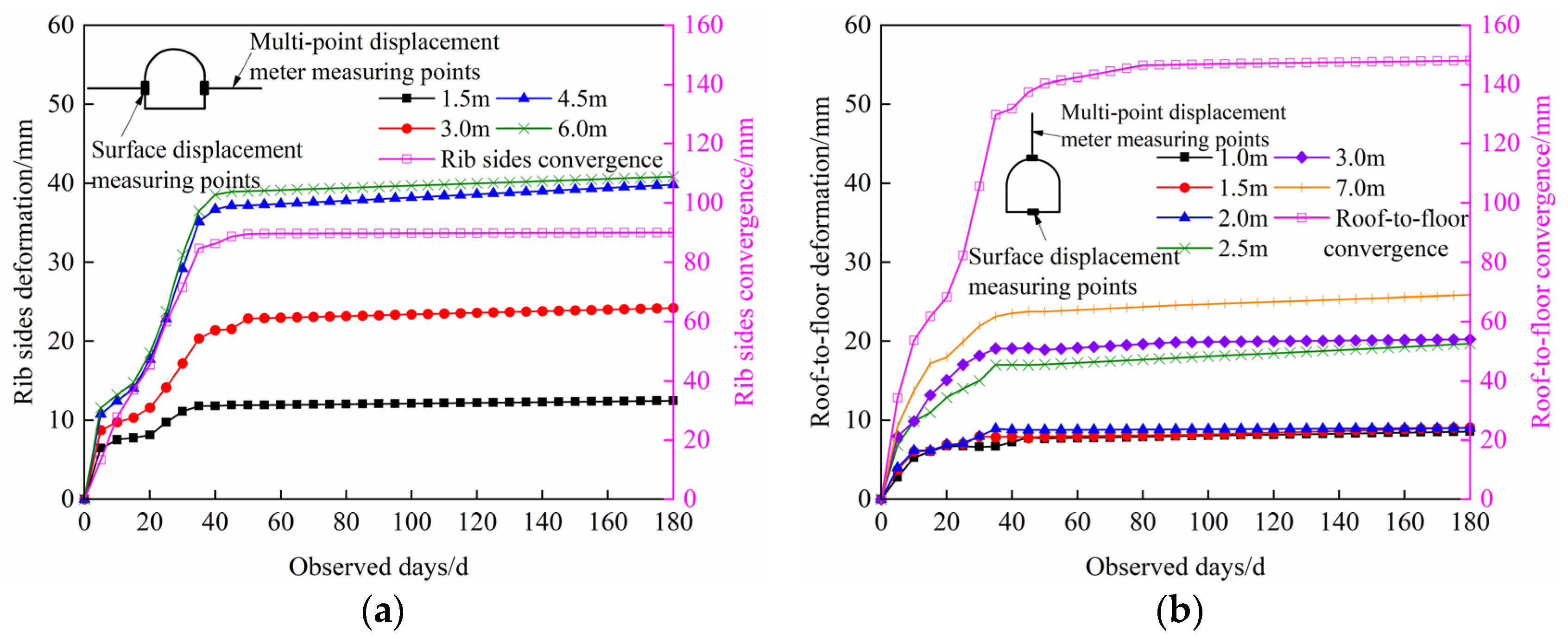
4.3. Bolt-Grouting Support Effect of Roadway

Based on the above bolting-grouting support scheme, the spatial distribution of grouting diffusion in the surrounding rock is obtained by numerical simulation, as shown in Figure 13. From Figure 13a, it can be found that the grout can form grouting reinforcement rings with thicknesses of 1.85 m and 3.45 m in the roof and floor, respectively. As shown in Figure 13b, the diffusion length of grout in the yz-direction is 3.04 m, beyond the plastic zone of 1.64 m, and the diffusion length of grout in the xy-direction is 2.6 m. This shows that the grout can fill and cement fractured rock mass. The grouting bolts are placed deep into the intact surrounding rock to make the damage zone and the intact surrounding rock form a whole structure, thereby improving the integrity and bearing capacity of the damage surrounding rock. This also shows that the spacing and row spacing arrangement of the grouting bolt is reasonable.
To further test the rationality of the grouting bolt spacing/row spacing arrangement, the deformation of the roof, floor, and two ribs of the roadway was monitored by the cross-section convergence meter and the multiple-position extensometer. The monitoring points and results can be seen in Figure 14. Figure 14 shows that the convergence of roof-to-floor and rib sides is large in the early stage of roadway formation. About 40 days after roadway formation, the deformation convergence of roadway roof-to-floor and rib sides slow down and gradually tend to be stable. It is also shown in Figure 14 that the surrounding rock deformation is less than 40 mm at a depth of 6 m from the surface of the rib, while the displacement of the rib sides is less than 90.1 mm (Figure 14a). The maximum deformation of surrounding rock 7 m deep from the roof surface is less than 30 mm, while the roof and floor movement are less than 148.1 mm (Figure 14b). These deformations meet the design stability requirements. It shows that adopting the bolt-grouting support scheme can effectively control the surrounding rock deformation and improve the stability of surrounding rock. It also shows that according to the distribution characteristics of plastic zone and grout diffusion, the length, spacing, and row spacing of grouting bolts arranged are scientific and reasonable. In addition, from an economic point of view, it can significantly save costs, which can provide technical and methodological guidance for the design of bolt-grouting support in deep roadway surrounding rock.

5. Conclusions

(1)
According to the Mohr–Coulomb strength criterion and Darcy’s flow, a unidirectional coupling model of surrounding rock plastic fracture and grouting diffusion considering excavation disturbance stress was established.
(2)
Under the three-dimensional unequal ground stress, the horizontal ground stress (i.e., λx), which is perpendicular to the axial direction of the roadway, is one of the main factors inducing roadway failure. The more significant the difference of the ground stress in three directions, the greater the plastic failure range in the roof corner and floor corner of roadway. Moreover, the plastic failure range in the roof and floor is greater than it of the same horizontal ground stress.
(3)
When the horizontal lateral pressure coefficient λxλy, the grout diffused forms as an approximate ellipsoid, i.e., the diffusion length of grout in the shallow surrounding rock is larger than that in the deep surrounding rock. Furthermore, the larger the ratio of λx/λy, the larger the diffusion length of grout in each spatial direction of surrounding rock. When λx < λy, the grout diffuses in the surrounding rock and presents an approximate cylinder, and the increase in the ratio of λy/λx has little effect on the grouting diffusion length.
(4)
Adopting the bolt-grouting support, the length of the grouting bolt/cable should be greater than the plastic failure zone of the surrounding rock. The spacing of the grouting bolt/cable should be 0.92–1.07 times the diffusion length of grout in the cross-section of the roadway, and the row spacing of the grouting bolt/cable should be 1.34–1.60 times the diffusion length of grout in the axial plane of the roadway.
(5)
An optimization method of bolt-grouting support parameters was proposed, which determines the type and length of grouting bolt based on the plastic failure zone and its distribution, and determines the spacing and row spacing of grouting bolt/cable by the diffusion length of grout along with the space. This bolt-grouting support method was applied to the engineering practice of bolt-grouting support in the deep roadway with high ground stress. The field and numerical results show that the bolt-grouting support effectively controls the surrounding rock deformation. This support method can be used as a reference to improve the stability of roadway surrounding rock.

Author Contributions

Conceptualization, Y.H.; Data curation, Y.H. and W.Y.; Formal analysis, Y.H. and W.Y.; Investigation, Y.H. and W.Y.; Methodology, Y.H. and W.Y.; Software, Y.H., W.Y. and Y.L.; Supervision, Y.H., W.Y., Y.L. and W.G.; Writing—original draft, Y.H.; Writing—review and editing Y.H., W.Y., Y.L. and W.G. All authors have read and agreed to the published version of the manuscript.

Funding

This research was funded by the National Natural Science Foundation of China (Grant No. 51604214, 52004205), the Natural Science Foundation of Shaanxi Province (Grant No. 2019JQ-381), and the Project funded by China Postdoctoral Science Foundation (Grant No.2016M592818).

Data Availability Statement

The data used to support the findings of this study are available from the corresponding author upon request.

Acknowledgments

First of all, I would like to thank Yaoguang Huang for his guidance and valuable suggestions in the process of writing this paper. I would also like to thank Weibin Guo for his comments on this paper.

Conflicts of Interest

The authors declare that there is no conflict of interest.

References

  1. Li, G.; Ma, F.S.; Guo, J.; Zhao, H.J. Case study of roadway deformation failure mechanisms: Field investigation and numerical simulation. Energies 2021, 14, 1032. [Google Scholar] [CrossRef]
  2. Liu, Q.S.; Sun, L.; Tang, X.H. Investigate the influence of the in-situ stress conditions on the grout penetration process in fractured rocks using the combined finite-discrete element method. Eng. Anal. Bound. Elem. 2019, 106, 86–101. [Google Scholar] [CrossRef]
  3. Luo, Y.; Xu, K.; Huang, J.H.; Li, X.P.; Liu, T.T.; Qu, D.X.; Chen, P.P. Impact analysis of pressure-relief blasting on roadway stability in a deep mining area under high stress. Tunn. Undergr. Sp. Tech. 2021, 110, 103781. [Google Scholar] [CrossRef]
  4. Yang, R.S.; Li, Y.L.; Guo, D.M.; Yao, L.; Yang, T.M.; Li, T.T. Failure mechanism and control technology of water-immersed roadway in high-stress and soft rock in a deep mine. Int. J. Min. Sci. Technol. 2017, 27, 245–252. [Google Scholar] [CrossRef]
  5. Yang, B.B.; He, M.M.; Zhang, Z.Q.; Zhu, J.W.; Chen, Y.S. A New Criterion of Strain Rockburst in Consideration of the Plastic Zone of Tunnel Surrounding Rock. Rock Mech. Rock Eng. 2022, 1, 1–13. [Google Scholar] [CrossRef]
  6. Cao, R.H.; Cao, P.; Hang, L. Support technology of deep roadway under high stress and its application. Int J. Min. Sci. Technol. 2016, 26, 787–793. [Google Scholar] [CrossRef]
  7. Chen, S.M.; Wu, A.X.; Wang, Y.M.; Chen, X.; Yan, R.F.; Ma, H.J. Study on repair control technology of soft surrounding rock roadway and its application. Eng. Fail. Anal. 2018, 92, 443–455. [Google Scholar] [CrossRef]
  8. Zhang, G.C.; Zang, C.W.; Chen, M.; Tao, G.Z.; Li, Y.; Hou, W.; Weng, H.; Zhao, D. Ground response of entries driven adjacent to a retreating longwall panel. Int J. Rock. Mech. Min. 2021, 138, 104630. [Google Scholar]
  9. Wang, F.Y.; Qian, D.L. Difference solution for a circular tunnel excavated in strain-softening rock mass considering decayed confinement. Tunn. Undergr. Sp. Tech. 2018, 82, 66–81. [Google Scholar] [CrossRef]
  10. Deng, J.; Ren, S.J.; Xiao, Y.; Shu, C.M. Mechanical properties of coal and rock mass under thermo-mechanical coupling. Arab J. Geosci. 2019, 12, 398. [Google Scholar] [CrossRef]
  11. Keawsawasvong, S.; Ukritchon, B. Design equation for stability of shallow unlined circular tunnels in Hoek-Brown rock masses. Bull. Eng. Geol. Environ. 2020, 79, 4167–4190. [Google Scholar] [CrossRef]
  12. Ukritchon, B.; Keawsawasvong, S. Lower bound stability analysis of plane strain headings in Hoek-Brown rock masses. Tunn. Undergr. Sp. Tech. 2019, 84, 99–112. [Google Scholar] [CrossRef]
  13. Xiao, Y.; Zhang, R.; Zhao, M.H.; Jiang, J.Q. Stability of Unlined Rectangular Tunnels in Rock Masses Subjected to Surcharge Loading. Int. J. Geomech. 2021, 21, 04020233. [Google Scholar] [CrossRef]
  14. Zhang, R.; Xiao, Y.; Zhao, M.H.; Zhao, H. Stability of dual circular tunnels in a rock mass subjected to surcharge loading. Comput. Geotech. 2019, 108, 257–268. [Google Scholar] [CrossRef]
  15. Shi, H.; Song, L.; Zhang, H.Q.; Chen, W.L.; Lin, H.S.; Li, D.Q.; Wang, G.Z.; Zhao, H.Y. Experimental and numerical studies on progressive debonding of grouted rock bolts. Int. J. Min. Sci. Technol. 2022, 32, 63–74. [Google Scholar] [CrossRef]
  16. Kumar, R.; Mandal, P.K.; Narayan, A.; Das, A.J. Evaluation of load transfer mechanism under axial loads in a novel coupler of dual height rock bolts. Int. J. Min. Sci. Technol. 2021, 31, 225–232. [Google Scholar] [CrossRef]
  17. Wang, Q.; He, M.C.; Li, S.C.; Jiang, Z.H.; Wang, Y.; Qin, Q.; Jiang, B. Comparative study of model tests on automatically formed roadway and gob-side entry driving in deep coal mines. Int. J. Min. Sci. Technol. 2021, 31, 591–601. [Google Scholar] [CrossRef]
  18. Pan, R.; Wang, Q.; Jiang, B.; Li, S.C.; Sun, H.B.; Qin, Q.; Yu, H.C.; Lu, W. Failure of bolt support and experimental study on the parameters of bolt-grouting for supporting the roadways in deep coal seam. Eng. Fail. Anal. 2017, 80, 218–233. [Google Scholar] [CrossRef]
  19. Wang, Q.; Jiang, Z.H.; Jiang, B.; Gao, H.K.; Huang, Y.B.; Zhang, P. Research on an automatic roadway formation method in deep mining areas by roof cutting with high-strength bolt-grouting. Int. J. Rock. Mech. Min. Sci. 2020, 128, 104264. [Google Scholar] [CrossRef]
  20. Ma, N.J.; Li, J.; Zhao, Z.Q. Distribution of deviatoric and plastic zone in circular roadway of surrounding rock J. China Univ. Min. Technol. 2015, 44, 206–213. [Google Scholar]
  21. Guo, X.F.; Zhao, Z.Q.; Gao, X.; Wu, X.Y.; Ma, N.J. Analytical solutions for characteristic radii of circular roadway surrounding rock plastic zone and their application. Int. J. Min. Sci. Technol. 2019, 29, 263–272. [Google Scholar] [CrossRef]
  22. Shang, X.J.; Zhang, Z.Z. Elastic-plastic-damaged zones around a deep circular wellbore under non-uniform loading. Symmetry 2020, 12, 323. [Google Scholar] [CrossRef] [Green Version]
  23. Yu, W.J.; Wu, G.S.; Yuan, C.; Wang, P.; Du, S.H. Failure characteristics and engineering stability control of roadway surrounding rock based on deviatoric stress field. J. China Coal Soc. 2017, 42, 1408–1419. [Google Scholar]
  24. Huang, Y.G.; Zhang, T.J. Plastic failure characteristics and grouting support of deep roadway with high ground stress. J. Min. Saf. Eng. 2019, 36, 949–958. [Google Scholar]
  25. Wang, H.W.; Zhang, D.Q.; Deng, D.X.; Jiang, Y.D.; Liu, Y.Y. Stress distribution characteristics of roadway surrounding rock damaged zone under non-hydrostatic pressure. J. China Coal Soc. 2020, 45, 3717–3725. [Google Scholar]
  26. Wang, W.J.; Dong, E.Y.; Yuan, C. Boundary equation of plastic zone of circular roadway in non-axisymmetric stress and its application. J. China Coal Soc. 2019, 44, 112–121. [Google Scholar]
  27. Wen, J.L.; Yang, W.L.; Liu, Y.; Shu, C.X. Rock burst and instability analysis for coal roadways based on unified strength theory. Int. J. Earth Sci. 2016, 9, 2161–2165. [Google Scholar]
  28. Wang, R.; Liu, X.D.; Bai, J.B.; Yan, S.; Xu, J. An innovative elastoplastic analysis for soft surrounding rock considering supporting opportunity based on drucker-prager strength criterion. Adv. Civ. Eng. 2021, 2021, 1–9. [Google Scholar] [CrossRef]
  29. Zhao, Y.L.; Zhang, L.Y.; Wang, W.J.; Tang, J.Z.; Hang, L.; Wen, W. Transient pulse test and morphological analysis of single rock fractures. Int. J. Rock. Mech. Min. Sci. 2017, 91, 139–154. [Google Scholar] [CrossRef]
  30. Zheng, W.X.; Bu, Q.W.; Hu, Y.Q. Plastic failure analysis of roadway floor surrounding rocks based on unified strength theory. Adv. Civ. Eng. 2018, 2018, 1–10. [Google Scholar] [CrossRef]
  31. Huang, Y.G.; Zhao, A.N.; Zhang, T.J.; Guo, W.B. Plastic failure zone characteristics and stability control technology of roadway in the fault area under non-uniformly high geostress: A case study from Yuandian Coal Mine in Northern Anhui Province, China. Open Geosci. 2020, 12, 406–424. [Google Scholar] [CrossRef]
  32. Huang, Y.G.; Wang, L.G.; Zhang, J.H. Reinforcement mechanism and slurry diffusion law of deep-shallow coupled fully bolting-grouting in deep broken roadway. Electron. J. Geotech. Eng. 2014, 19, 6319–6330. [Google Scholar]
  33. Liu, X.W.; Hu, C.; Liu, Q.S.; He, J. Grout penetration process simulation and grouting parameters analysis in fractured rock mass using numerical manifold method. Eng. Anal. Bound. Elem. 2021, 123, 93–106. [Google Scholar] [CrossRef]
  34. Geng, P.; Lu, Z.K.; Ding, T.; Quan, Q.L.; Yan, Q.X. Research on the dynamic process simulation of rock grouting based on particle flow. J. Railw. Eng. Soc. 2017, 34, 34–40. [Google Scholar]
  35. Yang, P.; Li, T.B.; Deng, T.; Xue, S.B. Effect of different factors on propagation of carbon fiber composite cement grout in a fracture with flowing water. Constr. Build. Mater. 2016, 121, 501–506. [Google Scholar] [CrossRef]
  36. Zhou, Z.L.; Du, X.M.; Chen, Z.; Zhao, Y.L. Grouting pressure of exponential fluids based on Navier–Stokes equation. J. Cent. South. Univ. 2017, 48, 1824–1830. [Google Scholar]
  37. Zhang, W.J.; Li, S.C.; Wei, J.C.; Zhang, Q.S.; Liu, R.T.; Zhang, X.; Yin, H.Y. Grouting rock fractures with cement and sodium silicate grout. Carbonates Evaporites 2018, 33, 211–222. [Google Scholar] [CrossRef]
  38. Liu, Q.S.; Sun, L. Simulation of coupled hydro-mechanical interactions during grouting process in fractured media based on the combined finite-discrete element method. Tunn. Undergr. Sp. Tech. 2019, 84, 472–486. [Google Scholar] [CrossRef]
  39. Sun, L.; Grasselli, G.; Liu, Q.S.; Tang, X.H. Coupled hydro-mechanical analysis for grout penetration in fractured rocks using the finite-discrete element method. Int. J. Rock Mech. Min. 2019, 124, 104138. [Google Scholar] [CrossRef]
  40. Xue, Y.; Dang, F.; Li, R.; Fan, L.; Hao, Q.; Mu, L.; Xia, Y. Seepage-stress-damage coupled model of coal under geo-stress influence. CMC Comput. Mater. Con. 2018, 54, 43–59. [Google Scholar] [CrossRef]
  41. Louis, C. Rock Hydraulics in Rock Mechanics; Springer: New York, NY, USA, 1974; pp. 33–68. [Google Scholar]
  42. Li, C.; Xu, J.H.; Pan, J.Z.; Ma, C. Plastic zone distribution laws and its types of surrounding rock in large-span roadway. Int. J. Min. Sci. Technol. 2012, 22, 23–28. [Google Scholar] [CrossRef]
  43. Xiao, T.Q.; Wang, X.Y.; Zhang, Z.G. Stability control of surrounding rocks for a coal roadway in a deep tectonic region. Int. J. Min. Sci. Technol. 2014, 24, 171–176. [Google Scholar] [CrossRef]
  44. He, M.M.; Zhang, Z.I.; Zhu, J.W.; Li, N. Correlation Between the Constant mi of Hoek–Brown Criterion and Porosity of Intact Rock. Rock Mech. Rock Eng. 2021, 55, 923–936. [Google Scholar] [CrossRef]
  45. Xue, Y.; Liu, J.; Liang, X.; Wang, S.H.; Ma, Z.Y. Ecological risk assessment of soil and water loss by thermal enhanced methane recovery: Numerical study using two-phase flow simulation. J. Clean. Prod. 2022, 334, 130183. [Google Scholar] [CrossRef]
  46. Zeng, K.H.; Li, X.J.; Lu, S.S.; Li, H.L. Unified plastic solutions of a circular tunnel under two unequal pressures and its applications. Chin. J. Geotech. Eng. 2022, 1–8. [Google Scholar]
  47. China Coal Association. Technical Specifications for Rock Bolting in Coal Mine Roadways. State Administration for Market Regulation; Standardization Administration of China: Beijing, China, 2018; GB/T 35056-2018: 2018-05-14.
Figure 1. Unidirectional coupling numerical model.
Minerals 12 00296 g001
Figure 2. Distribution characteristics of plastic failure of roadway surrounding rock. (a) Plastic zone on xz plane, (b) plastic zone on yz plane, (c) plastic zone on xy plane. (a1) λx = 1, λy = 1; (a2) λx = 2, λy = 2; (a3) λx = 3, λy = 3; (a4) λx = 1, λy = 0.75; (a5) λx = 2, λy = 0.75; (a6) λx = 3, λy = 0.75; (a7) λx = 0.75, λy = 1; (a8) λx = 0.75, λy = 2; (a9) λx = 0.75, λy = 3; (b1) λx = 1, λy = 1; (b2) λx = 2, λy = 2; (b3) λx = 3, λy = 3; (b4) λx = 1, λy = 0.75; (b5) λx = 2, λy = 0.75; (b6) λx = 3, λy = 0.75; (b7) λx = 0.75, λy = 1; (b8) λx = 0.75, λy = 2; (b9) λx = 0.75, λy = 3; (c1) λx = 1, λy = 1; (c2) λx = 2, λy = 2; (c3) λx = 3, λy = 3; (c4) λx = 1, λy = 0.75; (c5) λx = 2, λy = 0.75; (c6) λx = 3, λy = 0.75; (c7) λx = 0.75, λy = 1; (c8) λx = 0.75, λy = 2; (c9) λx = 0.75, λy = 3.
Minerals 12 00296 g002
Figure 3. Plastic zone of surrounding rock in different locations of the roadway. (a) λx = λy; (b) λx > λy, λy = 0.75; (c) λx < λy, λx = 0.75.
Minerals 12 00296 g003
Figure 4. Diffusion morphology of grout under different lateral coefficients. (a) λx = 3, λy = 3; (b) λx = 3, λy = 0.75; (c) λx = 0.75, λy = 3.
Minerals 12 00296 g004
Figure 5. Spatial distribution characteristics of grout pressure head. (a) λx = 1, λy = 1; (b) λx = 3, λy = 3; (c) λx = 1, λy = 1; (d) λx = 3, λy = 3; (e) λx = 1, λy = 1; (f) λx = 3, λy = 3; (g) λx = 1, λy = 0.75; (h) λx = 3, λy = 0.75; (i) λx = 1, λy = 0.75; (j) λx = 3, λy = 0.75; (k) λx = 1, λy = 0.75; (l) λx = 3, λy = 0.75; (m) λx = 0.75, λy = 1; (n) λx = 0.75, λy = 3; (o) λx = 0.75, λy = 1; (p) λx = 0.75, λy = 3; (q) λx = 0.75, λy = 1; (r) λx = 0.75, λy = 3.
Minerals 12 00296 g005
Figure 6. Cut-off diagram of diffusion length of grout.
Minerals 12 00296 g006
Figure 7. Change curve of grout pressure head with distance from the grouting borehole surface. (a) λx = λy, vertical borehole in x-direction; (b) λx = λy, vertical borehole in y-direction; (c) λx = λy, parallel borehole in z-direction; (d) λx > λy, vertical borehole in x-direction; (e) λx > λy, vertical borehole in y-direction; (f) λx > λy, parallel borehole in z-direction; (g) λx < λy, vertical borehole in x-direction; (h) λx < λy, vertical borehole in y-direction; (i) λx < λy, parallel borehole in z-direction.
Minerals 12 00296 g007
Figure 8. Diffusion length of grout under different lateral pressure coefficients. (a) Diffusion range of grout on yz plane; (b) diffusion range of grout on xz plane; (c) diffusion range of grout on xy plane.
Minerals 12 00296 g008
Figure 9. Grouting bolt layout and grout diffusion effect in cross-section (i.e., xz plane) of roadway. (a) Spacing 2.68 m; (b) spacing 1.79 m; (c) spacing 1.53 m; (d) spacing 1.34 m.
Minerals 12 00296 g009
Figure 10. Grouting bolt layout and grout diffusion effect in horizontal and vertical longitudinal section (i.e., xy plane and yz plane) of roadway. (a) Row spacing of 2.0 m; (b) row spacing of 2.5 m; (c) row spacing of 3.0 m; (d) row spacing of 3.5 m.
Minerals 12 00296 g010
Figure 11. Numerical model and plastic failure characteristics of the three-level main roadway. (a) Numerical model; (b) spatial distribution of plastic failure; (c) plastic zone in yz plane; (d) plastic zone in xz plane; (e) plastic zone in xy plane.
Minerals 12 00296 g011
Figure 12. Bolt-grouting support scheme for roadway. 1—Sprayed concrete; 2—Φ22 × L 2000 mm high-strength resin bolt; 3—grouting bolt.
Minerals 12 00296 g012
Figure 13. Gout diffusion effect within surrounding rock after grouting. (a) Cross section (xz plane) of roadway; (b) vertical section (yz plane) of roadway; (c) vertical section (yx plane) of roadway.
Minerals 12 00296 g013
Figure 14. Deformation and convergence of roadway surrounding rock. (a) Roadway rib. (b) roadway roof and floor.
Minerals 12 00296 g014
Table 1. Physical and mechanical parameters of the surrounding rock and grout.
Rock Mass Density
ρ (kg·m−3)
Elasticity
Modulus
E (GPa)
Poisson’s
Ratio
μ
Cohesion
C (MPa)
Friction Angle
Φ (°)
Grouting Pressure Head
H (m)
Grouting Unit Weightγ (N·m−3)Initial
Permeability
Coefficient
K0 (m/s)
Grout
Storage
Coefficient
μs (m−1)
Macroscopic Test Parameters a
2000100.253.531285.714001.5 × 10−50.3−0.0875
Table 2. Theoretical and numerical solutions of plastic zone range in the two-dimensional circular roadway.
Horizontal
Lateral Pressure Coefficient
λx = 1λx = 1.5
Damage LocationRoofRoof CornerRibFloor CornerFloorRoofRoof CornerRibFloor CornerFloor
Numerical solution (m)1.331.481.701.401.332.341.631.151.652.27
Theoretical solution (m)1.301.301.301.301.302.341.680.881.682.34
Relative error (%)2.3113.8530.777.692.310.002.9830.681.793.00
Table 3. Theoretical and numerical solutions of plastic zone range in the three-dimensional roadway.
Horizontal Lateral Pressure Coefficientλx = 1λx = 1.5
Damage LocationRoofRoof CornerRibFloor CornerFloorRoofRoof CornerRibFloor CornerFloor
Numerical solution (m)0.540.330.430.240.001.040.660.000.261.92
Theoretical solution (m)0.720.720.720.720.721.370.960.440.961.37
Relative error (%)2554.1740.2866.67----24.0931.25-----72.9240.14
Table 4. Diffusion lengths of grout in different directions at different distances from the roadway surface.
Lateral Pressure CoefficientDiffusion Length of Grout/m
Distance from Roadway Surface/m
0.5 m1.5 m2.5 m3.5 m4.5 m
xyxyxyxyxy
λx = 1.0, λy = 1.01.301.191.251.091.251.421.221.201.041.48
λx = 1.5, λy = 1.51.541.771.331.551.341.491.271.231.061.52
λx = 2.0, λy = 2.01.651.981.951.871.421.541.311.401.071.59
λx = 2.5, λy = 2.52.062.532.021.991.471.571.351.881.081.63
λx = 3.0, λy = 3.02.233.712.13.191.772.291.611.891.311.66
λx = 1.0, λy = 0.751.361.171.311.091.251.431.251.21.051.56
λx = 1.5, λy = 0.751.541.741.591.561.341.491.291.231.061.64
λx = 2.0, λy = 0.751.702.241.661.871.421.551.331.511.071.64
λx = 2.5, λy = 0.752.162.842.053.001.481.571.461.891.091.67
λx = 3.0, λy = 0.752.313.992.123.401.802.291.722.021.431.68
λx = 0.75, λy = 1.01.271.171.251.071.211.421.221.201.051.56
λx = 0.75, λy = 1.51.271.171.251.071.211.421.221.201.051.56
λx = 0.75, λy = 2.01.281.171.251.071.211.421.221.201.051.56
λx = 0.75, λy = 2.51.281.171.251.071.211.421.221.201.051.56
λx = 0.75, λy = 3.01.281.171.251.071.211.421.221.201.051.56
Table 5. Rock columnar and its physical-mechanical parameters.
ColumnarLithologyThickness (m)Density (kg·m−3)Cohesion (MPa)Friction Angle (°)Elastic Modulus (GPa)Poisson’s Ratio
Minerals 12 00296 i001Fine sandstone8.627002.203012.310.22
Minerals 12 00296 i002Mudstone2.021503.22616.50.22
Minerals 12 00296 i00310 coal5.814001.2282.660.33
Minerals 12 00296 i004Mudstone4.123002.82916.50.22
Minerals 12 00296 i005Fine sandstone and siltstone coexist with each other44.326002.03012.510.25
Minerals 12 00296 i006Mudstone11.424002.52816.50.23
Publisher’s Note: MDPI stays neutral with regard to jurisdictional claims in published maps and institutional affiliations.

