Communication

Multi-Step Recycling of BF Slag Heat via Biomass for CO2 Mitigation

1
Steel Institute (IEHK), RWTH Aachen University, 52062 Aachen, Germany
2
Badische Stahl-Engineering GmbH, 77694 Kehl, Germany
3
Independent Researcher, 52062 Aachen, Germany
*
Author to whom correspondence should be addressed.
Minerals 2022, 12(2), 136; https://doi.org/10.3390/min12020136
Submission received: 3 December 2021 / Revised: 20 January 2022 / Accepted: 20 January 2022 / Published: 25 January 2022

Abstract

:
Iron- and steelmaking processes create slags, valuable by-products. Industrial utilisation of slag as a lower-value secondary mineral source has been established for decades. Slag heat recovery is an ongoing research topic and has the potential to maximise energy efficiency in iron and steel production. Heat recuperation aims to tap the unused thermal recycling potential of molten slags. This short communication expands the concept for the utilisation of recovered heat for producing torrefied biomass and biogas. The torrefaction process is linked with slag heat recovery and via the BASE method with enhanced blast furnace operation. Such a combination reduces CO2 emissions significantly in ironmaking processes. Assuming a coke consumption of 350 kg coke per tonne of hot metal and replacing it with 5% torrefied biomass injected as PC with an additional 100 m3/tHM biogas injection, the BF’s CO2 emission related to the coke can be lowered by 7.9% to 108 kg/tHM. In such a manner, the recovered slag heat can directly contribute to CO2-footprint reduction and improve the circular economy and metallurgical sustainability.

1. Introduction

Iron- and steelmaking processes create slags, valuable by-products. Industrial utilisation of slag as a lower value secondary mineral source has been established for decades. Current research focuses on, e.g., the recovery of non-ferrous metals such as chromium via leaching [1] and the carbonisation of slags for carbon capture and storage (CCS) [2]. Slag heat recovery has been a well-studied, ongoing research topic for many decades and has the potential to maximise energy efficiency in iron and steel production. Nevertheless, the utilisation of such heat has not yet directly contributed to CO2-mitigation methods such as linking it with torrefied biomass (TB) and biogas preparation for partial blast furnace (BF) coke replacement. The present work is a continuation of previous work [3] describing slag heat recovery and, briefly, three utilisation possibilities: (1) heating of BF hot stoves, (2) syngas production via the high-temperature Winkler process, and (3) drying of biomass. This short communication depicts the drying of biomass and expands it by low-temperature pyrolysis to obtain torrefied biomass and biogas.

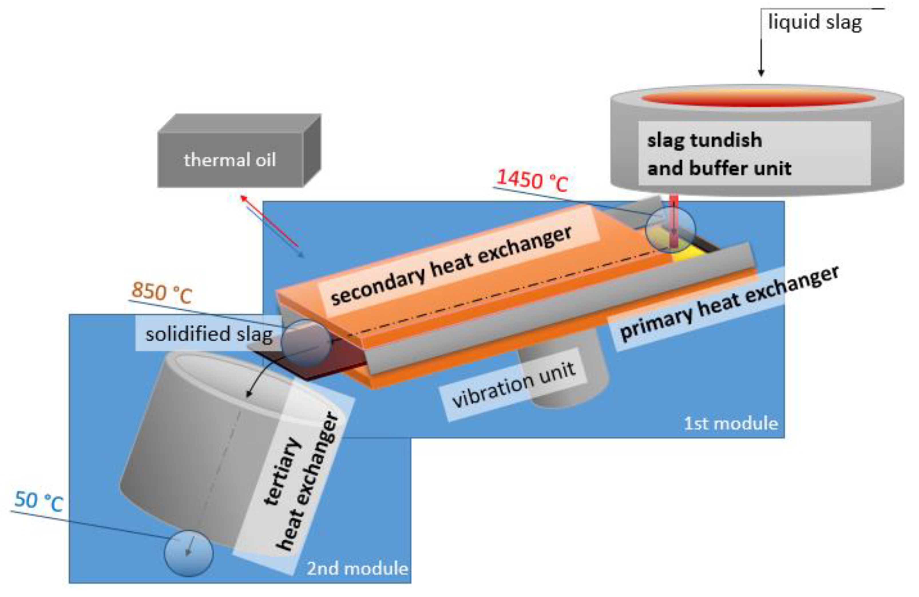
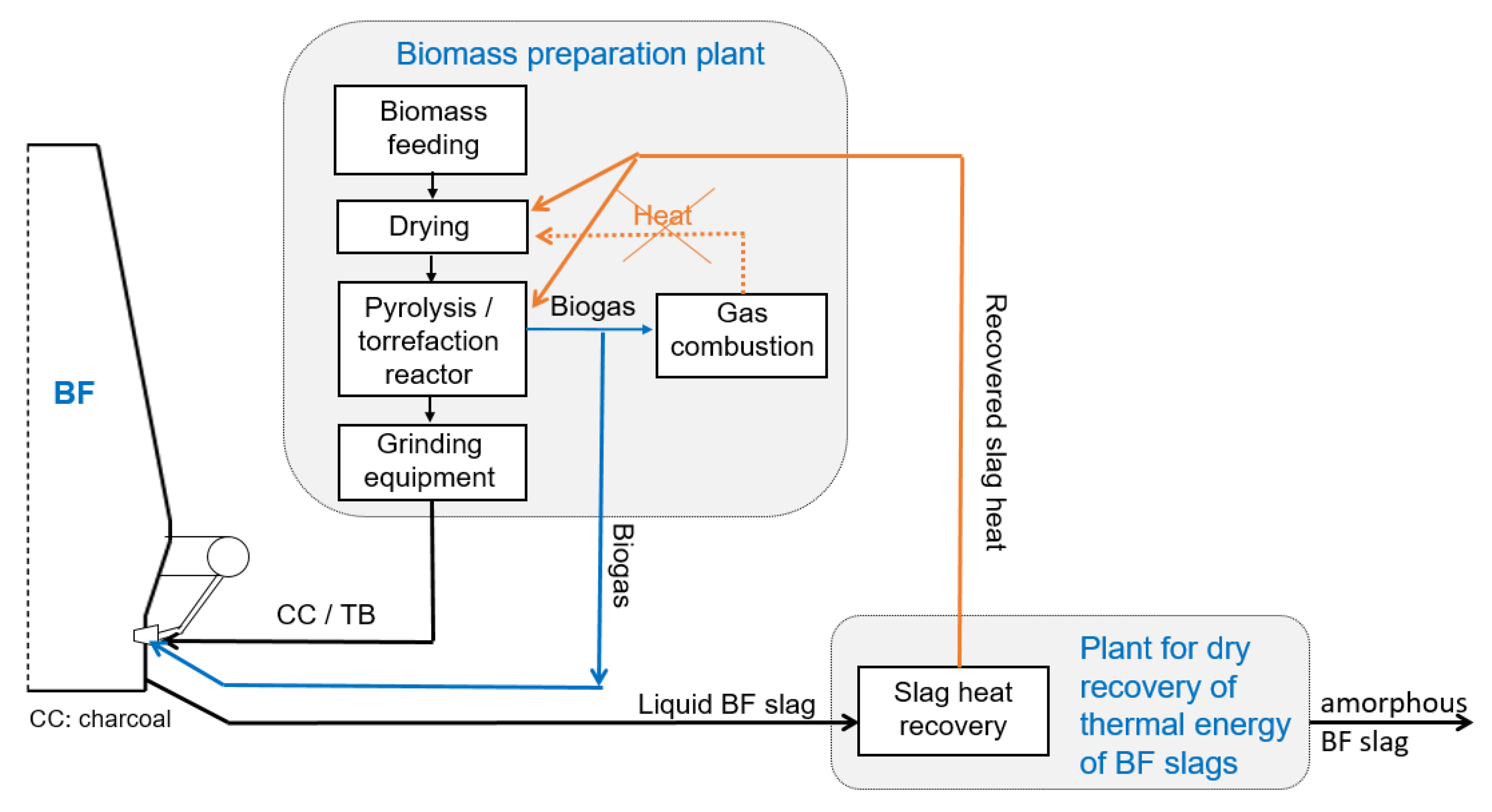
2. Description of the Slag Heat Recovery Concept

The recovery of heat from slags has been a global problem for many decades and has already been addressed by many institutions and projects [4]. In general, the industrial application was impeded either due to technical difficulties (e.g., low heat-recovery efficiency, insufficient vitrification of blast furnace slag) or due to missing economic feasibility. While technical difficulties can be overcome, the economic context can only change with politically induced changes such as the EU taxonomy introduced by the European green deal and CO2 emission trading systems (EU ETS) introducing the cost for each tonne of emitted CO2 gas. Table 1 gives an overview of the main slag heat recovery approaches.
The approach for dry heat recovery depicted in Figure 1 was investigated at RWTH Aachen University, Aachen, Germany [15,16], and has recently been shown in detail [3]; therefore, the process is only briefly described below. In general, the process involves capturing energy from metallurgical slags by using an indirect cooling system with water or thermal oil and transmitting the slag’s heat energy to subsequent heat exchangers for utilisation. The apparatus consists of two main modules and a facultative slag tundish. The first module cools liquid slag from tapping temperature (e.g., 1450 °C) to below the blast furnace slag’s glass transition temperature, which is around 850 °C. The heat is extracted via conduction from the bottom side of the slag (Primary Heat Exchanger, PHE) with a copper plate and via convection and radiation from the slag’s upside via copper pipes (Secondary Heat Exchanger, SHE). When the slag leaves the first module in a solid amorphous state, it enters the second module, where it cools down to local ambient temperature via convection in bulk (Tertiary Heat Exchanger, THE).
These two modules, including the slag tundish, were tested at a lab scale, and their energy recuperation was quantified [3] with a total thermal recuperation of 42%, considering a latent heat capacity of 1.7 GJ/t. The measured recuperation indicates a recovery equal to 0.7 GJ/t slag. Electrical energy input has to be considered due to the vibrating unit and was quantified to be 0.3 × 10⁻² GJelectrical/t slag and, respectively, 0.4% of the recovered slag heat. The demonstrator tests were conducted with lab-scale slag amounts of 10 kg each and yielded >95 vol.% amorphous content for BF slag [3]. It was observed that the BF slag chemical composition did not significantly affect the slag heat recovery in the CaO/SiO2 range between 1.0 and 1.3 [16]. Specific heat losses are expected to decrease during upscaling, and the heat recovery might be further influenced by slag chemistry when the process is applied on, e.g., Brazilian charcoal blast furnaces with acidic BF slags.

3. Production of Torrefied Biomass and Biogas

Biomass is an organic material that can be derived from either plants or animals and is not of fossil origin. Due to its organic nature, plant biomass can be produced from various sources such as agricultural residues or food-processing wastes. When considering biomass for (re-)introduction in ironmaking to replace coal, the differences between biomass and fossil coal need to be pointed out. A suitable general specification for biomass is difficult. Principally, all biomass could be used, but minimising the differences to fossil coal reduces the possible negative impacts on the BF operations. To buffer such differences between biomass and coal, the pyrolysis process needs to be adapted. In the following, the basic differences of biomass to coal are listed ([17], p. 61):
  • Higher oxygen content (~40%);
  • Lower carbon content (40–60%);
  • Lower sulphur content (<0.1% S);
  • Higher chlorine and alkali (particularly potassium) content in herbaceous biomass (grasses, straws);
  • Low ash contents possible (<2%), depending on source very broad (0.1–25%);
  • Lower heating values;
  • Much lower bulk density;
  • More fibrous and less friable structure;
  • C/H and O/C ratios indicate the expected release.
Pyrolysis is a thermal process that decomposes carbon-containing material under an atmosphere with low or no levels of oxygen, hence an air–fuel equivalent ratio λ ≈ 0. Depending on the process temperature, three categories of pyrolysis are defined: low-temperatures pyrolysis at <500 °C, mid-temperature pyrolysis at 500–800 °C, and high-temperature pyrolysis at >800 °C. Torrefaction is low-temperature pyrolysis at <320 °C and produces solid, liquid, and gaseous products. Depending on the processing speed, slow, fast, and flash pyrolysis are distinguished and result in different ratios and yields of solid, liquid, and gaseous products [18].
The torrefied biomass (TB) contains volatile matter, which affects its characteristics by destroying its fibre structure. This makes the TB brittle, hence easier to grind and hydrophobic. Wet biomass (WB) has a heating value of around 8.3 MJ/kg if clean wood is considered. This value increases to 19 MJ/kg via drying and to 21.7 MJ/kg for torrefaction while releasing biogas. If processed at higher temperatures, it can reach values of 30 MJ/kg for charcoal [19]. The chemistry of TB depends on process temperature, oxygen content, and raw material used. The desired effects are increasing carbon content, decreasing oxygen content, and increasing calorific value. It was found [17] that the desired impact is large at high pyrolysis temperatures and negligible at low temperatures between 200 and 350 °C.
The main components of biogas from the torrefaction process are 29–47 vol.% CO and 8–20 vol.% H2 [20]. Biogas can have heating values similar to wet biomass of 8 MJ/kg and is usually conceptualised for providing heat in the drying step [6]. It might be sufficient for the torrefaction heat demand, depending on the initial moisture content.

4. Utilisation of Recuperated Thermal Energy

Coke in blast furnace ironmaking mainly contributes to CO2 emissions related to coal coking and iron ore reduction. Table 2 shows the specific CO2 emissions during blast furnace ironmaking in the account of coke. Based on an average coke consumption and a generic direct CO2 emission of coking, the coke-induced emissions are around 1.4 t/t hot metal.
Certain biomasses can be considered carbon-neutral depending on their origin, even when used as fuel [22]. The biomass plants captured the same amount or more of CO2 during their lifetime as during induration, which sums to a net-zero CO2 emission. Therefore, any substitution rate of coke by biomass reduces the blast furnace’s CO2 footprint by that relative amount of biomass used. The direct use of wet or dried biomass is less favourable due to its low physical and energetic density and the fact that its physical strength is insufficient to carry the blast furnace burden [23]. Their utilisation requires preparation by torrefaction or pyrolysis to produce TB or charcoal, respectively [17]. Torrefying biomass and injecting it as a pulverised coal (PC) alternative into the enhanced blast furnaces is an option to partially replace the specific consumption of coke. Furthermore, the coke consumption can be lowered with the injection of biogas as syngas [18] partially replacing or in addition to the hot blast, which is only carrying sensible heat. Such biogas injection and its effects can be compared to BF top gas recycling [24,25,26,27]. Usually, biogas is used for wet biomass drying and would reduce specific ironmaking CO2 emissions if injected into an enhanced BF. Alternatively, such biogas can be suitable as reducing gas in direct reduction processes such as Midrex, HyL/Energiron, and Hyfor, and torrefied biomass in SL/RN, Fastmet, Circofer, etc.
Before torrefied biomass and biogas can be considered for utilisation in the blast furnace, the energy supply by slag heat recovery has to be matched with the energy demand for torrefaction. Table 3 depicts the provided slag heat, recovered slag heat, and torrefaction energy demand. WB with an exemplary ash content of 0.5% and 50% moisture content requires 1.3 GJ/t WB and yields 0.37 t TB from 1 t WB [19]. Combining the energy demand with the recovered slag heat, 200 kg TB can be produced per 1 tonne of slag, respectively, 60 kg TB per tonne HM. Considering the specific coke consumption of 350 kg/t HM in Table 1, the TB produced with BF slag heat of this theoretical calculation could replace 17% of the coke for the same BF yielding 300 kg of slag per tonne HM.
Table 4 demonstrates the theoretical impact of partially replacing 5% of 350 kg coke per tonne hot metal with TB and additionally injecting it to PC (+17.5 kgTB/tHM) together with biogas injection of, e.g., 100 m3/tHM. Typical oxygen content in the blast due to TB are 25%, and combined biogas injection is between 30 and 40%, resulting in a flame temperature around 2117 °C [18]. The presented exemplary coke-replacement rates with TB and biogas of Table 4 are independent of mass and energy balances and need further investigation with case studies. The considered TB [18] has a moisture content of 2.3 wt.%, ash content of 0.6 wt.%, volatile matter of 6.0 wt.%, and a carbon value (Cfix) of 88.3 wt.%. The considered biogas has H2 of 35.7 vol.%, CO of 37.1 vol.%, CO2 of 9.7 vol.%, H2O of 4.0 vol.%, N2 of 13.5 vol.%, and no CH4 [18].
Figure 2 depicts the integration of slag heat recovery, torrefaction, TB, and biogas injection into the BF via the BASE control method [18].

5. Conclusions

Heat recuperation taps the currently unused thermal-recycling potential of molten slags. This short communication expands the concept of the utilisation of recovered heat for biomass torrefaction producing torrefied biomass and biogas. This work shows the link between the torrefaction process and slag heat recovery via the BASE method [18] with an enhanced blast furnace operation. Such a combination significantly reduces CO2 emissions in the ironmaking processes.
Assuming a coke consumption of 350 kg coke per tonne of hot metal and replacing it with 5% torrefied biomass injected as PC with an additional 100 m3/tHM biogas injection, the BF’s CO2 emission related to the coke can be lowered by 7.9% to 108 kg/tHM. In such a manner, the recovered slag heat can directly contribute to CO2 footprint reduction, further improving the circular economy and sustainability of the metallurgical processes.

6. Patents

DE102014109762A1: Wärmetauscher sowie Vorrichtung und Verfahren zur Energierückgewinnung. Inventor: Sebastian Buzga, Markus Hansen; Assignee: Z&J Technologies GmbH, Application: 11 July 2014; Publication: 14 January 2016.

Author Contributions

Conceptualisation, F.F., D.S. and A.B.; methodology, F.F.; validation, F.F., D.S. and A.B.; formal analysis, F.F.; investigation, F.F.; resources, D.S. and A.B.; data curation, F.F.; writing—original draft preparation, F.F.; writing—review and editing, D.S. and A.B.; supervision, D.S.; project administration, F.F.; funding acquisition, D.S. All authors have read and agreed to the published version of the manuscript.

Funding

This research received external funding from Z&J Technologies GmbH, Düren, Germany.

Institutional Review Board Statement

Not applicable.

Informed Consent Statement

Informed consent was obtained from all subjects involved in the study.

Data Availability Statement

Not applicable.

Acknowledgments

We thank Z&J Technologies GmbH and namely Sebastian Buzga for the funding, Salzgitter Flachstahl GmbH, and namely Jürgen Pethke for the support and fruitful discussions. Further thanks belong to Badische Stahl-Engineering for allowing his employer to further contribute to the present research and Michael Nispel for proofreading. We also thank “HeiWi” Gudenau for initiating the research on slag heat recovery.

Conflicts of Interest

The authors declare no conflict of interest. The funders had no role in the design of the study; in the collection, analyses, or interpretation of data; in the writing of the manuscript, or in the decision to publish the results.

References

  1. Pikna, L.; Hezelova, M.; Morillon, A.; Algermissen, D.; Milkovic, O.; Findorak, R.; Cesnek, M.; Briancin, J. Recovery of Chromium from Slags Leachates by Electrocoagulation and Solid Product Characterization. Metals 2020, 10, 1593. [Google Scholar] [CrossRef]
  2. Kremer, D.; Wotruba, H. Separation of Products from Mineral Sequestration of CO2 with Primary and Secondary Raw Materials. Minerals 2020, 10, 1098. [Google Scholar] [CrossRef]
  3. Firsbach, F.; Senk, D.; Babich, A. Process Concept for the Dry Recovery of Thermal Energy of Liquid Ferrous Slags. J. Sustain. Metall. 2021, 7, 783–793. [Google Scholar] [CrossRef]
  4. Yang, J.; Firsbach, F.; Sohn, I. Pyrometallurgical processing of ferrous slag “co-product” zero waste full utilization: A critical review. Resour. Conserv. Recycl. 2022, 178, 106021. [Google Scholar] [CrossRef]
  5. Barati, M.; Jahanshahi, S. Granulation and Heat Recovery from Metallurgical Slags. J. Sustain. Metall. 2020, 6, 191–206. [Google Scholar] [CrossRef]
  6. Bisio, G. Energy recovery from molten slag and exploitation of the recovered energy. Energy 1997, 22, 501–509. [Google Scholar] [CrossRef]
  7. Shigaki, N.; Tobo, H.; Ozawa, S.; Ta, Y.; Hagiwara, K. Heat recovery process from packed bed of hot slag plates. ISIJ Int. 2015, 55, 2258–2265. [Google Scholar] [CrossRef] [Green Version]
  8. Fujii, H.; Tanaka, K.; Nakamura, M.; Okuno, R.; Hashizume, S.; Katayama, H.; Fujita, T. Apparatus for Heat Recovery from Molten Slag. US Patent US4350326A, 21 September 1982. [Google Scholar]
  9. Shimizu, H.; Watanabe, M.; Koide, M.; Ueno, T.; Yutaka, A. Development of molten blast furnace slag granulator. Tetsu-Hagane 1983, 69, 29. [Google Scholar]
  10. Ando, J.; Onoue, H.; Nakahara, T.; Ichimura, S.; Kondo, M. Development of slag blast granulating plant characterized by innovation of the slag treatment method, heat recovery and recovery of slag as resources. Mitsubishi Heavy Ind. Technol. Rev. 1985, 22, 136–142. [Google Scholar]
  11. Yoshinaga, M.; Fujii, K.; Shigematsu, T.; Nakata, T. Dry granulation and solidification of molten blast furnace slag. Trans. Iron Steel Inst. Jpn. 1982, 22, 823–829. [Google Scholar] [CrossRef]
  12. Xie, D.; Jahanshahi, S.; Norgate, T. Dry granulation to provide a sustainable option for slag treatment. In Proceedings of the Sustainable Mining Conference, Kalgoorlie, Australia, 17–19 August 2010; pp. 22–28. [Google Scholar]
  13. Fleischanderl, A.; Fenzl, T.; Neuhold, R. Dry Slag Granulation for Slag Sand Production and Heat Recovery–Development Status of the Pilotplant at Blast Furnace A at Voestalpine. Miner. Nebenprodukte Abfälle 2019, 6, 228–245. [Google Scholar]
  14. Kappes, H.; Michels, D. Dry Granulation with Energy Recovery: Pilot Campaign at ROGESA. In Proceedings of the AISTech 2014, Indianapolis, IN, USA, 5–8 May 2014. [Google Scholar]
  15. Hüttenmeister, D. Entwicklung einer Anlage zur Amorphen Erstarrung Flüssiger Hochofenschlacke mit Gleichzeitiger Wärmerückgewinnung. Ph.D. Thesis, RWTH Aachen University, Aachen, Germany, 2015. [Google Scholar]
  16. Firsbach, F. Konstruktion und Prozesstechnische Optimierung einer Anlage zur Amorphen und Rekuperativen Erstarrung von Schlackensystemen Integrierter Hüttenwerke. Ph.D. Thesis, RWTH Aachen University, Aachen, Germany, 2018. [Google Scholar]
  17. Babich, A.; Senk, D. Biomass use in the steel industry: Back to the future? Stahl Eisen 2013, 133, 57–67. [Google Scholar]
  18. Babich, A.; Senk, D.; Solar, J.; de Marco, I. Efficiency of Biomass Use for Blast Furnace Injection. ISIJ 2019, 59, 2212–2219. [Google Scholar] [CrossRef] [Green Version]
  19. Koppejan, J.; Sokhansanj, S.; Melin, S.; Madrali, S. Status Overview of Torrefaction Technologies; Task 32 Report; IEA Bioenergy: Paris, France, 2019; pp. 2–5. [Google Scholar]
  20. Solar, J.; de Marco, I.; Caballero, B.M.; Lopez-Urionabarrenechea, A.; Rodriguez, N.; Agirre, I.; Adrados, A. Influence of temperature and residence time in the pyrolysis of woody biomass waste in a continuous screw reactor. Biomass Bioenergy 2016, 95, 416–423. [Google Scholar] [CrossRef]
  21. Steinparzer, T. The Pathway to Green Steel. Steel Times International Webinar “Sustainability & Steelmaking”. Available online: https://www.steeltimesint.com/news/sustainability-steelmaking (accessed on 22 January 2021).
  22. Woo, H.; Turner, P. A Review of Recent Research on Carbon Neutrality in Forest Bioenergy Feedstocks. Int. J. Environ. Sci. Nat. Res. 2019, 19, 556014. [Google Scholar] [CrossRef]
  23. Schwarz, M. Beitrag zur Energetischen und Stofflichen Verwertung von Biomasse in der Eisenmetallurgie: Biokoks und Reduktionsgas, IEHK, 1st ed. Ph.D. Thesis, RWTH Aachen University, Shaker Verlag, Aachen, Germany, 2019. [Google Scholar]
  24. Zhang, W.; Zhang, J.; Xue, Z.; Zou, Z.; Qi, Y. Unsteady Analyses of the Top Gas Recycling Oxygen Blast Furnace. ISIJ Int. 2016, 56, 1358–1367. [Google Scholar] [CrossRef] [Green Version]
  25. Zhang, W.; Xue, Z.g; Zahng, J.; Wang, W.; Cheng, C.; Zou, Z. Medium oxygen enriched blast furnace with top gas recycling strategy. J. Iron Steel Res. Int. 2017, 8, 778–786. [Google Scholar] [CrossRef]
  26. Zhang, W.; Dai, J.; Li, C.; Yu, X.; Xue, Z.; Saxén, H. A review on Explorations of the Oxygen Blast Furnace Process. Steel Res. Int. 2021, 92, 202000326. [Google Scholar] [CrossRef]
  27. Mousa, E.; Ahmed, H. Utilization of biomass as an alternative fuel in iron and steel making. In Iron Ore, 2nd ed.; Lu, L., Ed.; Woodhead Publishing: Duxford, UK, 2022; pp. 665–690. [Google Scholar]
  28. Nielson, S.; Okosun, T.; Damstedt, B.; Jampani, M.; Zhou, C.Q. Tuyere-Level Syngas Injection in the Blast Furnace: A Computational Fluid Dynamics Investigation. Processes 2021, 9, 1447. [Google Scholar] [CrossRef]
Figure 1. Scheme of the process concept [3].
Minerals 12 00136 g001
Figure 2. Scheme of the integration of slag heat recovery, pyrolysis/torrefaction, and biogas injection into the BF (further developed from [18]).
Minerals 12 00136 g002
Table 1. Summary of slag heat recovery concepts (further developed from [4]).
TechnologyDeveloperSourceEfficiencyCapacityProsCons
Rotating
drum
Sumitomo, [5]50–60%50 t/h
-
robust
-
limited wear of drums
-
high productivity
-
low temperature of heated water
-
limited to crystalline solidification
NKK,[6]40%-
JFE,[7]34%60 t/h
Mechanical
stirring
Kawasaki, [8]59%-
-
can be combined with slag ladle
-
decentral heat recovery away from slag-generating vessel
-
consecutive heat capture with inert gas and then with water
-
high wear of rod
Sumitomo, [9]50%30 t/h
Air blastingNKK and Mitsubishi, [5]40–50%60 t/h
-
safe and easy handling
-
fine, granular product
-
suitable for high quenching rates
-
high productivity
-
high efficiency is questionable
-
high electrical energy demand for hot blast
Mitsubishi, [10]81%80 t/h
Spinning
disc/cup
Sumitomo, [11]50–60%50 t/h
-
robust, as wear is limited to disc/cup
-
safe handling
-
high quenching rates
-
wear of copper disc/cup
-
low mass flows towards cup/disc limit productivity
CSIRO, [12]80%18–30 t/h
British Steel,[6]60%40 t/h
Primetals, [13]70%30–40 t/h
Steel sphere
injection
Paul Wurth, [14]-150 t/h
-
high productivity
-
able to cope with flow peaks of 4 t/min
-
robust and suitable for industrial operations
-
blast furnace slag vitrification did not reach >95 vol.%
Vibrating
chute
RWTH Aachen, and Z&J Technologies, [3]42%16 t/h
-
robust
-
higher temperatures of thermal oil vs. water
-
wear of copper chute
-
limited productivity
-
difficult handling of thermal oil
Table 2. Coke related CO2 emissions at the blast furnace.
ParameterValueUnit
Blast furnace coke consumption rate350kg/tHM 1
CO2 emission via coking270kg/tcoke 2
CO2 emission via coke gasification in BF 33667kg/tcoke
CO2 emission via coking and coke gasification3937kg/tcoke
CO2 emission of coke per hot metal1378kg/tHM
1 Hot Metal. 2 [21]. 3 C to CO2 conversion, excluding the impact of heating energy and excluding ash content.
Table 3. Energy balance of slag heat recovery and biomass torrefaction.
ParameterValueUnit
Slag volume300kg/tHM
Slag heat 11.7GJ/tslag
Slag heat recovery yield 142%
Recovered slag heat 10.7GJ/tslag
Recovered slag heat 10.2GJ/tHM
Energy required for drying and torrefaction 21.3GJ/tWB
Torrefaction mass yield wet biomass to torrefied biomass 237%
Energy required for drying and torrefaction 23.5GJ/tTB
TB producible with recovered slag heat0.20tTB/tslag
TB producible with recovered slag heat0.06tTB/tHM
TB producible with recovered slag heat17% (tTB/tcoke)
1 Values based on [3]. 2 Values based on [19].
Table 4. Description of the CO2-saving potential of an enhanced blast furnace in relation to Table 1 using torrefied biomass and biogas.
ParameterValueUnit
Rate of coke substituted by TB as PC5%
Coke substituted by 5% TB as PC−18kg/tHM
Coke substituted biogas injection into BF 1−10kg/tHM
Combined coke substitution by TB and biogas−28kg/tHM
CO2 reduction by combined substitution with TB and biogas 2−108kg/tHM
Relative CO2 emission abatement via TB and biogas−7.9%
1 Value estimation based on [18,28] with exemplary injection rates of 100 m3/tHM. 2 Value calculated by assuming coke’s CO2 footprint described in Table 1.
Publisher’s Note: MDPI stays neutral with regard to jurisdictional claims in published maps and institutional affiliations.

