Article

Separation of Copper-Molybdenum Flotation Concentrate by Superconducting High-Gradient Magnetic Separation

1
School of Resources and Environmental Engineering, Jiangxi University of Science and Technology, Ganzhou 341000, China
2
Ganzhou Innovation Center for Water Quality Security Technology at Ganjiang River Basin, Jiangxi University of Science and Technology, Ganzhou 341000, China
3
Shandong Huate Magnet Technology Co., Ltd., Weifang 261000, China
4
School of Architecture and Design, Jiangxi University of Science and Technology, Ganzhou 341000, China
*
Authors to whom correspondence should be addressed.
Minerals 2022, 12(10), 1191; https://doi.org/10.3390/min12101191
Submission received: 19 August 2022 / Revised: 19 September 2022 / Accepted: 19 September 2022 / Published: 22 September 2022
(This article belongs to the Special Issue High Gradient Magnetic Separation)

Abstract

:
Separation of chalcopyrite from molybdenite is currently mainly carried out by flotation, but this process is costly because of the extensive use of inhibitors. This study briefly describes a 7.0T/100CGC low-temperature superconducting magnetic separator and discusses its separation principle as well as the effect of magnetic induction on chalcopyrite separation from molybdenite. A molybdenum (Mo) concentrate assaying 6.00% copper (Cu) and 19.01% Mo was magnetically sorted using a diamond-shaped steel rod medium mesh at a feed concentration of 20% and a pulp flow rate of 5 L/min from a Cu-Mo flotation concentrate with 88% of particles smaller than 23 μm using the separator. A Mo concentrate assaying 0.46% Cu and 16.28% Mo was finally obtained with a roughing (1.3 T)-cleaning (5 T) superconducting magnetic separation process. Similarly, the superconducting magnetic separator was performed to separate a Cu-Mo bulk flotation concentrate, and produced Cu concentrate assaying 19.64% Cu and 0.03% Mo from the bulk concentrate assaying 18.52% Cu and 0.39% Mo with a particle size of less than 0.074 mm. At a magnetic induction of 7 T, a pulp concentration of 20% and a feed velocity of 5 L/min, the grade and recovery of Cu in the magnetic product were 19.64% and 81.59%, respectively, whereas the grade and recovery of Mo in the non-magnetic product were 1.52% and 90.07%, respectively. Superconducting magnetic separation has potential applications for removing Cu from Mo concentrates, and separating Cu and Mo from Cu-Mo bulk flotation concentrates.

1. Introduction

About 50% of the world’s Mo is stored in porphyry Cu-Mo ores [1,2]. In common practice, Cu-Mo ores are often recovered together from sulphide minerals (bulk flotation) [3], followed by flotation to separate Cu from Mo. Satisfactory results are generally obtained in bulk flotation processes. Chalcopyrite (CuFeS2) and molybdenite (MoS2) are difficult to separate because of their high natural floatability [4,5]. Large quantities of reagents must be added during flotation, resulting in high production and environmental costs [6,7].
Many studies have been carried out to explore more environment-friendly and effective methods for separating chalcopyrite from molybdenite, such as the development of more environment-friendly and efficient organic inhibitors. Examples include dithiocarbamate chitosan, tiopronin, humic acids, tragacanth gum, etc. [3,8,9,10]. The high cost of using these organic inhibitors limits their industrial application. Some researchers pretreat the raw material prior to flotation by heating [11], electrocatalytic [12], and plasma washing [13] to increase the difference in floatability between chalcopyrite and molybdenite, which makes it easier to separate them during subsequent flotation. This method leads to additional energy consumption and has not yet been used in industry. In addition, there has been a separation of chalcopyrite from a fine Cu-Mo mixed flotation concentrate by a pulsing high gradient magnetic separation process [12]. The final recoveries obtained are 30%–40% for Cu and 6%–10% for Mo in the magnetic product, whereas the recoveries are 60%–70% and 90%–94% for Cu and Mo in the non-magnetic product. It is theoretically feasible to use magnetic separation to separate chalcopyrite from molybdenite. The magnetic susceptibility of chalcopyrite is 0.840 × 10⁻⁶ m3/kg, whereas that of molybdenite is −0.001 × 10⁻⁶ m3/kg. To obtain a better separation, a greater magnetic induction is required during magnetic separation because of the smaller magnetic difference between them.
Superconducting High Gradient Magnetic Separation (SHGMS) is a technology developed on the basis of the High Gradient Magnetic Separation (HGMS) technology of the 1970s [14]. Its magnetic field strength reaches 3~7 T, which is several times that of ordinary electromagnetic magnetic separators. The main advantages of SHGMS are high separation efficiency, low operating costs, and a non-polluting separation process. The technology therefore demonstrates great potential for treating wastewater and separating weakly magnetic minerals [15]. To our knowledge, no one has reported the separation of Cu and Mo using superconducting magnetic separation technology. In this study, a pilot study on the separation of Cu and Mo from a mixed Cu-Mo concentrate produced from a Mo mine was carried out using a superconducting magnetic separator. The theoretical basis of the superconducting magnetic separation process was discussed, and the effect of the ultra-high magnetic field strength of the superconducting magnetic separation on the separation performance was explored using experimental data. These results will provide theoretical support for the separation of chalcopyrite from molybdenite and create economic and environmental benefits for companies.

2. Materials and Methods

2.1. Materials

The Cu-Mo material (Table 1) (Sample 1) with 19.01% Mo, 6.00% Cu, and 14.48% Fe was obtained from the Jinduicheng Mo Group Co., Ltd. in Shaanxi Province, China. About 88% of the particles in this material are smaller than 23 μm
Another bulk flotation concentrate (Sample 2) obtained from the Dexing Cu mine in Jiangxi Province, China was attempted for Cu-Mo separation. Ferromagnetic minerals in the material were removed using a 0.8 T magnetic bar. Then, a chemical multi-element analysis revealed that the Cu content was 18.52% and the Mo content was 0.39% in this material. The main non-magnetic gangues in the material are quartz (SiO2), mica (KAl2[Si3AlO10](OH)2), and a small amount of the sulfide mineral pyrite (FeS2). Magnetic separation efficiency may be reduced due to the interference from pyrite. In order to be closer to the actual production site, this material was not subjected to secondary grinding. All particles in the material are less than 0.074 mm.

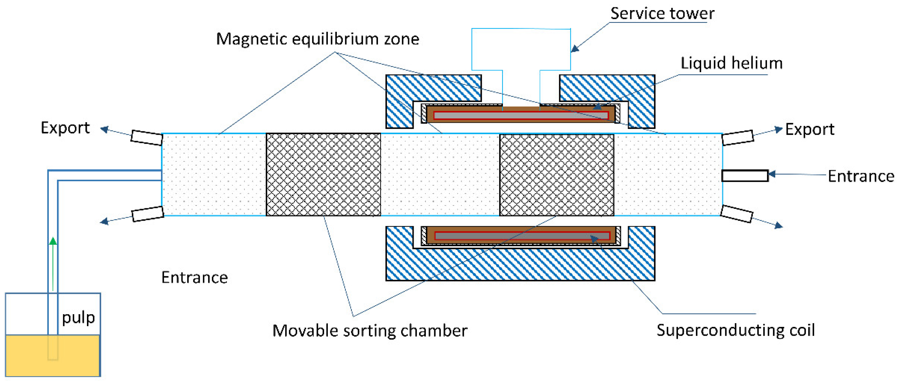
2.2. Method and Evaluation

Separation of chalcopyrite and molybdenite was achieved using a 55-piece diamond-shaped steel rod media mesh. The performance of the superconducting magnetic separator was evaluated using Cu grades and recoveries from the magnetic product and Mo grades and recoveries from the non-magnetic product. Grades of Cu and Mo in the product were obtained by chemical multi-element analysis. The recoveries are calculated based on elemental balances as follows:
ε = β × γ α × 100 %
where ε is the recovery of the target element, α is the grade of the target element in the raw ore, β is the grade of Cu in the magnetic product or Mo in the non-magnetic product, and γ is the yield of the magnetic or non-magnetic product.

2.3. Mechanism Analysis

A 7.0T/100CGC low-temperature superconducting magnetic separator produced by Shandong Huate Co., Ltd. was used here (Figure 1). In this magnetic separator, the magnetic induction can reach 7 T. The separation principle of the low temperature superconducting magnetic separator is similar to that of an ordinary high-gradient magnetic separator [15,16]. The major difference is that the low-temperature superconducting magnetic separator has a much higher magnetic flux. The overall structure of the low-temperature superconducting magnetic separator is divided into three parts, as shown in Figure 2: the sorting system, the magnet, and the drive system. The core system that achieves the separation of fine particles of minerals is the sorting system.
The separation system of the superconducting magnetic separator is shown in Figure 3. In the ready state, the power excitation is applied to the superconducting coil and the magnetic separator reaches a predetermined magnetic induction with an excitation time of less than 1 h. Once the superconducting magnetic separator reaches the predetermined magnetic induction, the power supply stops the excitation and maintains this magnetic induction. Noticeably, the pre-set magnetic induction can be adjusted in real time between 0 and 7T. The closed-loop refrigeration technology is used to condense the vaporised helium back into liquid helium so that the helium does not evaporate to the outside of the magnet, ensuring that the total amount of liquid helium remains constant during magnetic separation. The liquid helium keeps the operating temperature of the superconducting coil below the superconducting temperature of 4.2 K. At this point, the coil resistance is zero and it is in a superconducting state. During this process, only the cryogenic chiller (with a power of approx. 13 kW) remains in operation. This makes the energy-saving advantages of the superconducting magnetic separator very obvious compared to the high-gradient magnetic.
When the superconducting coils complete their excitation, the sorting chamber within the sorting system is in magnetic equilibrium. This allows the motor to use less force to drive the magnets in a round-trip motion. As the pulp passes through the high gradient magnetic field zone, the chalcopyrite particles with a large specific magnetization coefficient will overcome fluid resistance and attach to the magnetic media mesh. The relatively less magnetic particles of molybdenite are discharged from the outlet with the flow of the pulp. After switching off the power, the chalcopyrite particles are taken out of the magnetic medium by the water flow. The separation of chalcopyrite and molybdenite has been achieved.
The potential energy possessed by a mineral particle in a magnetic field obeys the following equation:
U = 1 2 B H V
where U is the potential energy of a mineral particle in a magnetic field, B is the magnetic induction, V is the volume of the particle, and H is the strength of the magnetic field. Moreover, magnetic induction and magnetic field strength can be converted to each other by Equation (3):
B = μ H
where μ is the magnetic permeability of the mineral particles. Combining Equations (2) and (3) gives the following equation:
U = 1 2 μ H 2 V
All else being equal, Equation (4) indicates that the potential energy of a mineral particle in a magnetic field is proportional to its magnetic permeability. The greater magnetic permeability means the potential energy is higher and it is more likely to be driven by magnetic forces. The magnetic force on a mineral particle in a magnetic field obeys Equation (5):
F m = 𝛻 U
where F m is the magnetic force acting on the mineral particles in the magnetic field and 𝛻 is the operator for the gradient. Combining Equations (4) and (5) yields Equation (6) [17]:
U = 1 2 μ H 2 V 𝛻
If the mineral particles are treated as spheres, it is not difficult to obtain Equation (7):
F m = 1 6 π x D 3 B 𝛻 B
where D is the diameter of the mineral particle and х is the volume magnetic susceptibility of the mineral. Clearly, magnetic induction is proportional to the magnetic force on the mineral particle in the magnetic field when all other conditions are constant. If the particle diameter is too small, the magnetic force on the mineral particle is also substantially reduced. When the volume and volume magnetic susceptibility of the mineral are small, the magnetic induction needs to be increased in order to trap the fine, weakly magnetic mineral particles. Superconducting magnetic separators benefit from their high magnetic induction and are effective in separating weakly magnetic minerals.
In addition, the trapping of mineral particles in the magnetic field depends on the amount of fluid resistance. Assume that the velocity and direction of pulp movement during magnetic separation are constant and that the mineral particles are uniformly distributed in the fluid. Then, the fluid resistance is represented as follows:
F = F 1 + F 2 + F 3
where F is the fluid resistance to the mineral particle, F 1 is the drag force to be overcome by the mineral particle changing its motion in the fluid, F 2 is the additional mass force of the mineral particle moving towards the magnetic medium in the fluid, and F 3 is the Basset force due to the change in acceleration as the mineral particle moves towards the magnetic medium. Equations (9)–(11) can be used to express F 1 , F 2 , and F 3 :
F 1 = 1 8 π D 2 ρ ( Δ v ) 2 C D
where ρ is the density of the mineral particles, Δ v is the velocity difference between the fluid and the mineral particles, and C D is the drag coefficient:
F 2 = 1 6 π D 3 ρ ( 1 + ρ f 2 ρ ) d v d t
where ρ f is the density of the fluid and d v d t is the acceleration of the mineral particles in the fluid:
F 3 = 3 2 D 2 ( π ρ f μ f ) 1 2 t 0 t ( t t * ) 1 2 d ( Δ v ) d t · d t
where μ f is the viscosity of the fluid, t 0 is the initial moment at which the acceleration change in the mineral particles occurs, and t* is the integration variable. When a mineral particle moves in a fluid towards a magnetic medium, it is subjected to a magnetic force greater than the fluid resistance. This process can be described in Equation (12):
F m F > 0
Combining Equations (7)–(12) gives the conditions under which mineral particles are magnetically trapped in a magnetic field:
1 6 π х D 3 B 𝛻 B 1 8 π D 2 ρ ( Δ v ) 2 C D 1 6 π D 3 ρ ( 1 + ρ f 2 ρ ) d v d t 3 2 D 2 ( π ρ f μ f ) 1 2 t 0 t ( t t · ) 1 2 d ( Δ v ) d t · d t > 0

3. Results and Discussion

3.1. Separation of Mixed Ores with High Molybdenum Content

The maximum Cu content that can be accepted in a Mo concentrate is 0.5% [18]. Small amounts of mixed chalcopyrite can be magnetically separated from high-grade molybdenite ores. This is because chalcopyrite is more magnetic than molybdenite. As the magnetic field strength increases, chalcopyrite and molybdenite are concentrated in the magnetic product and the non-magnetic product, respectively.
The experiment results with a 7.0T/100CGC low temperature superconducting magnetic separator to separate molybdenite and chalcopyrite from high-grade Mo bearing ores are shown in Figure 4. The experiments were divided into two stages that were separated using a superconducting magnetic separator and pulsed at a frequency of 45 Hz. In the first stage, a magnetic induction of 1.3 T was used to remove the magnetic iron from the material. In the second stage, a magnetic induction of 5 T was used to separate molybdenite and chalcopyrite. If the superconducting magnetic separator is to be utilized industrially, the processing capacity of the superconducting magnetic separator must be increased. As a result, the feed velocity and concentration of the superconducting magnetic separator were initially set at 5 L/min and 20%, which were much higher than the feed velocity and concentrations of the other superconducting magnetic separators employed in the study [19]. This improvement will significantly increase the daily throughput of the superconducting magnetic separator if it can be used in industry. As shown in Figure 4, the 7.0T/100CGC low temperature superconducting magnetic separator can reduce the Cu grade in the non-magnetic product to 0.46% under neutral conditions, with a Cu removal rate of 92.33%. At pH 4, the Cu grade in the non-magnetic product was 0.67% and the Cu removal was 88.83%. These results indicate that neutral conditions are more favourable for Cu and Mo separation than acidic conditions. In addition, a high level of Mo is present in the magnetic iron product. The reason may be that the high feed concentration and the presence of abundant Cu-Mo inclusions result in a low recovery of Mo in the non-magnetic product. In conclusion, the superconducting magnetic separator can produce Mo concentrates with less than 0.5% Cu and has potential applications for the removal of Cu from Mo concentrates.

3.2. Separation of Mixed Ores with High Copper Content

3.2.1. Effect of Magnetic Induction on the Separation of Copper and Molybdenum

The separation performance of the 7.0T/100CGC low-temperature superconducting magnetic separator for mixed ores with high Cu content is shown in Figure 5. Clearly, magnetic induction has a very strong influence on grade and recovery. A suitable magnetic induction should maximally enrich Cu in the magnetic product and Mo in the non-magnetic product during the separation process. The chalcopyrite is a direct band-gap p-type semiconductor with a conductivity of 1 to 10 Ωm, and the orientation of the atomic magnetic moment is altered by the magnetic field exerting a force on the moving charges in the mineral particles. Free electrons are more plentiful in chalcopyrite, and charge movement will be more likely to occur compared to molybdenite. The atomic magnetic moments of chalcopyrite are more likely to be redirected when the particles are subjected to greater external magnetic induction. Chalcopyrite particles in the pulp will be subjected to greater magnetic forces in an inhomogeneous magnetic field. In the macroscopic manifestation, more chalcopyrite particles are concentrated in the magnetic product.
The recovery of Cu from the magnetic product increases substantially as the magnetic induction increases (Figure 5). The reason is that when all other conditions are equal, the magnetic force on a mineral particle in a magnetic field is proportional to the magnitude of the magnetic induction. The higher magnetic induction results in a greater magnetic force on the mineral particles and a higher recovery rate. In addition, the recovery and grade of Mo in the non-magnetic product increases significantly with the increasing magnetic induction. The increased magnetic induction is beneficial for Mo concentration in the non-magnetic product. With all things considered, 7 T was chosen as the preferred condition.
Noticeably, there is a peak in Cu grade in the magnetic product at 5 T. This is identical to another report [16], even if the composition of the ore used is inconsistent. This may indicate that when the magnetic induction is 5 T, the magnitude of the magnetic force on the chalcopyrite particles in the magnetic field is just greater than the fluid resistance, so the chalcopyrite is adsorbed to the magnetic separation media. As the magnetic induction continues to increase, pyrite, which is less magnetic than chalcopyrite in the pulp, is similarly captured and frictional cross-linking between the two particles further leads to a reduction in the grade of Cu in the magnetic product [20].

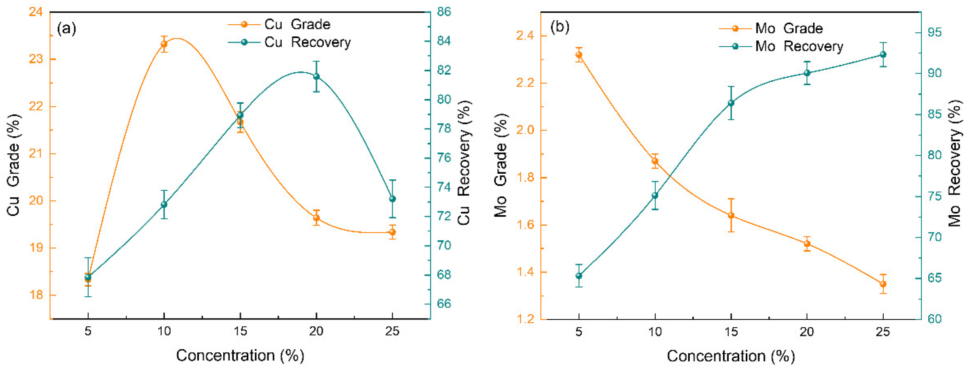
3.2.2. Effect of Pulp Concentration on Copper-Molybdenum Separation

Pulp concentration is an important factor affecting fluid resistance. When the slurry concentration increases, the fluid resistance also increases, which facilitates an increase in the grade of Cu in the magnetic product. With the increase in pulp concentration, the grade of Cu in the magnetic product first increases and then decreases, and the recovery of Cu continues to increase. The grade of Mo in the non-magnetic product decreases, and the recovery of Mo increases (Figure 6). This is because when the fluid resistance of the pulp increases, the less magnetic Mo is subjected to a smaller trapping force from the magnetic field, which makes the Mo particles more likely to be enriched in the non-magnetic product. Gangue in the pulp is also enriched in the non-magnetic product, which results in a reduction in Mo grade. In addition, when the pulp concentration is increased, more chalcopyrite and molybdenite particles are present in the magnetic field, so chalcopyrite particles are more likely to be captured. The Cu grade and recovery of the magnetic product were improved. When the pulp concentration is excessive, the fluid resistance is overly high and the magnetic force on the chalcopyrite particles is less than the fluid resistance, so more chalcopyrite particles are lost in the non-magnetic product. As a result, the recovery of chalcopyrite particles in the magnetic product decreases. On balance, a concentration of 20% was chosen as the preferred condition.
When the pulp concentration is 10%, the grade of Cu peaks. The reason may be that as the pulp concentration increases, the mechanical entrainment between the mineral particles in the pulp becomes more intense [21,22]. Chalcopyrite particles are trapped along with pyrite particles by magnetic induction of 7 T. Because of mechanical entrainment, the recovery of pyrite is getting higher and higher, and the Cu grade is beginning to decrease. Cu recovery peaked at 20% pulp concentration. The reason may be that when the pulp concentration is too high, the chalcopyrite particles accumulate too quickly in the magnetic medium, and the retained mineral particles on the magnetic medium collide with the high concentration of pulp, which leads to the loss of Cu.

3.2.3. Effect of Feed Velocity on Copper-Molybdenum Separation

The feed velocity affects the residence time of the mineral particles in the magnetic field. In general, at the faster feed velocity, the residence time of the mineral particles in the magnetic field is shorter. The effect of feed velocity on the Cu-Mo separation is shown in Figure 7, where the relatively more magnetic chalcopyrite particles in the pulp are preferentially captured, which leads to an increase in the grade of Cu in the magnetic product. Increasing the feed velocity makes fine chalcopyrite particles enter the non-magnetic minerals, and the recovery of Cu in the magnetic product is consistently reduced.
As the feed velocity increases, the grade of Mo in the non-magnetic product consistently decreases and the recovery gradually increases. Noticeably, the reduction in Mo grade is not significant, but the increase in recovery is noticeable. This is a result of the increased kinetic energy of the fluid due to the increased feed rate and the greater drag forces that need to be overcome for the mineral particles to change motion in the fluid, which benefits the enrichment of the less magnetic mineral particles in the non-magnetic product. On balance, 5 L/min was chosen as the preferred condition. At a magnetic induction of 7 T, a pulp concentration of 20%, and a feed velocity of 5 L/min, the grade and recovery of Cu in the magnetic product were 19.64% and 81.59%, respectively; whereas, the grade and recovery of Mo in the non-magnetic product were 1.52% and 90.07%, respectively. These results indicate that Cu and Mo were effectively separated.
The peak grade of Cu occurs when the feed velocity is 5 L/min. The reason for this may be that at a feed velocity of 5 L/min, the magnetic force is exactly equal to the fluid resistance. When the feed velocity is less than 5 L/min, the magnetic force is greater than the fluid resistance, and the chalcopyrite particles captured by the magnetic medium cannot be flushed by the pulp into the non-magnetic product, at which time the grade of Cu increases; when the feed velocity is greater than 5L/min, the magnetic force is less than the fluid resistance, and the chalcopyrite particles on the magnetic medium are flushed by the pulp into the non-magnetic product, resulting in a decrease in the recovery of Cu.
The calibration experiments were carried out under optimal conditions, and the process and results are shown in Figure 8. After superconducting magnetic separation, 20.15% Cu and 0.04% Mo were assayed in the magnetic product, and 13.35% Cu and 1.51% Mo were assayed in the non-magnetic product. The recoveries were 82.72% for Cu and 7.19% for Mo in the magnetic product, as well as 17.28% for Cu and 92.81% for Mo in the non-magnetic product.
The enrichment efficiency of superconducting magnetic separation was analysed using the Hancock–Luyken formula [23]. Equation (14) is a specific form of the Hancock–Luyken formula.
E = [(R − γ)/(100 − α)] × 100%
where E is the enrichment efficiency, R is the recovery of the target element, γ is the yield of the concentrate, and α is the content of the target element in the raw ore. Superconducting magnetic separation will be compared with flotation and high gradient magnetic separation to determine its level of enrichment efficiency.
A comparison of the enrichment efficiencies of the different methods [24,25] is shown in Figure 9. The enrichment efficiency of superconducting magnetic separation was calculated under optimum conditions. The enrichment efficiency of Cu in the magnetic product (Cu concentrate) from superconducting magnetic separation was only 8.21%, which was lower than the 11.55% for high gradient magnetic separation and 19.54% for flotation. The reason is that more pyrite in the raw ore is enriched in the magnetic product, and the enrichment efficiency of Cu is reduced. It is worth noting that the enrichment efficiency of Mo in the non-magnetic product (Mo concentrate) from superconducting magnetic separation was 69.11%, higher than the 21.79% from high gradient magnetic separation and lower than the 72.20% from flotation. This indicates that superconducting magnetic separation relies heavily on the selective enrichment of Mo to separate Cu and Mo under optimal conditions.

4. Conclusions

Superconductivity tests on different Cu-Mo mixed minerals were conducted.
(1) Superconducting magnetic separation can effectively remove Cu from Mo concentrates. A non-magnetic product grading 0.46% Cu and 16.28% Mo was obtained from a Mo concentrate with a Cu content of 6.0% after a magnetic induction of 0.3 T and a magnetic induction of 5 T. In this process, the Cu removal rate was 92.33%. Superconducting magnetic separation technology is potentially promising for removing Cu from Mo concentrates.
(2) Superconducting magnetic separation can effectively achieve the separation of Cu and Mo. At a magnetic induction of 7 T, a pulp concentration of 20%, and a feed velocity of 5 L/min, the grade and recovery of Cu in the magnetic product were 19.64% and 81.59%, respectively, whereas the grade and recovery of Mo in the non-magnetic product were 1.52% and 90.07%, respectively. Superconducting magnetic separation can completely replace a part of the flotation process or reduce the flotation processing capacity, saving costs and creating greater profit margins for enterprises.
(3) The recovery of Cu in the magnetic product and Mo in the non-magnetic product gradually increases with the increase in the magnetic induction. An increase in magnetic induction will facilitate the recovery of Cu and Mo, but too much magnetic induction will adversely affect the grade of Cu in the magnetic product, which is shown experimentally to be a satisfactory condition at 7 T.

Author Contributions

Z.W. (Zekai Wang); Writing—original draft, visualization, X.L.; conceptualization ideas, project administration, Z.W. (Zhaolian Wang); methodology, resources, W.H.; funding acquisition, methodology, G.L.; investigation, C.Z.; investigation, L.H.; writing—review and editing. All authors have read and agreed to the published version of the manuscript.

Funding

This research was funded by The National Natural Science Foundation of China (grant No. 51864017).

Data Availability Statement

Not applicable.

Acknowledgments

The authors would like to thank the editors and reviewers for their excellent support.

Conflicts of Interest

We declare that we have no financial and personal relationships with other people or organizations that can inappropriately influence our work, there is no professional or other personal interest of any nature or kind in any product, service and/or company that could be construed as influencing the position presented in, or the review of, the manuscript entitled.

References

  1. Abdollahi, M.; Bahrami, A.; Mirmohammadi, M.S.; Kazemi, F.; Danesh, A.; Ghorbani, Y. A process mineralogy approach to optimize molybdenite flotation in copper – molybdenum processing plants. Miner. Eng. 2020, 157, 106557. [Google Scholar] [CrossRef]
  2. Yuan, D.; Cadien, K.; Liu, Q.; Zeng, H. Adsorption characteristics and mechanisms of O-Carboxymethyl chitosan on chalcopyrite and molybdenite. J. Colloid Interface Sci. 2019, 552, 659–670. [Google Scholar] [CrossRef] [PubMed]
  3. Hao, J.; Liu, J.; Yang, D.; Qin, X.; Gao, H.; Bai, X.; Wen, S. Application of a new depressant dithiocarbamate chitosan in separation of chalcopyrite and molybdenite. Colloids Surf. A Physicochem. Eng. Asp. 2022, 634, 127920. [Google Scholar] [CrossRef]
  4. Wang, X.; Zhao, B.; Liu, J.; Zhu, Y.; Han, Y. Dithiouracil, a highly efficient depressant for the selective separation of molybdenite from chalcopyrite by flotation: Applications and mechanism. Miner. Eng. 2022, 175, 107287. [Google Scholar] [CrossRef]
  5. Wang, C.; Liu, R.; Wu, M.; Xu, Z.; Tian, M.; Yin, Z.; Sun, W.; Zhang, C. Flotation separation of molybdenite from chalcopyrite using rhodanine-3-acetic acid as a novel and effective depressant. Miner. Eng. 2021, 162, 106747. [Google Scholar] [CrossRef]
  6. Yi, G.; Macha, E.; Van Dyke, J.; Ed Macha, R.; McKay, T.; Free, M.L. Recent progress on research of molybdenite flotation: A review. Adv. Colloid Interface Sci. 2021, 295, 102466. [Google Scholar] [CrossRef] [PubMed]
  7. Pan, C.-L.; Wei, X.-X.; Zhang, X.-G.; Xu, Y.-W.; Xu, P.-F.; Luo, Y.-C. 2-((5-Mercapto-1,3,4-thiadiazol-2-yl)thio)acetic acid as a novel chalcopyrite depressant for selective flotation separation of molybdenite from chalcopyrite. Miner. Eng. 2022, 183, 107625. [Google Scholar] [CrossRef]
  8. Yang, B.; Yan, H.; Zeng, M.; Zhu, H. Tiopronin as a novel copper depressant for the selective flotation separation of chalcopyrite and molybdenite. Sep. Purif. Technol. 2021, 266, 118576. [Google Scholar] [CrossRef]
  9. Yuan, D.; Cadien, K.; Liu, Q.; Zeng, H. Selective separation of copper-molybdenum sulfides using humic acids. Miner. Eng. 2019, 133, 43–46. [Google Scholar] [CrossRef]
  10. Zhong, C.; Feng, B.; Wang, H.; Chen, Y.; Guo, M. The depression behavior and mechanism of tragacanth gum on chalcopyrite during Cu-Mo flotation separation. Adv. Powder Technol. 2021, 32, 2712–2719. [Google Scholar] [CrossRef]
  11. Tang, X.; Chen, Y.; Liu, K.; Zeng, G.; Peng, Q.; Li, Z. Selective flotation separation of molybdenite and chalcopyrite by thermal pretreatment under air atmosphere. Colloids Surf. A Physicochem. Eng. Asp. 2019, 583, 123958. [Google Scholar] [CrossRef]
  12. Peng, W.; Liu, S.; Cao, Y.; Wang, W.; Lv, S.; Huang, Y. A novel approach for selective flotation separation of chalcopyrite and molybdenite – Electrocatalytic oxidation pretreatment and its mechanism. Appl. Surf. Sci. 2022, 597, 153753. [Google Scholar] [CrossRef]
  13. Hirajima, T.; Mori, M.; Ichikawa, O.; Sasaki, K.; Miki, H.; Farahat, M.; Sawada, M. Selective flotation of chalcopyrite and molybdenite with plasma pre-treatment. Miner. Eng. 2014, 66-68, 102–111. [Google Scholar] [CrossRef]
  14. Li, Y.; Li, S.; Hu, B.; Zhao, X.; Guo, P. FeOOH and nZVI combined with superconducting high gradient magnetic separation for the remediation of high-arsenic metallurgical wastewater. Sep. Purif. Technol. 2022, 285, 120372. [Google Scholar] [CrossRef]
  15. Qi, Z.; Joshi, T.P.; Liu, R.; Li, Y.; Liu, H.; Qu, J. Adsorption combined with superconducting high gradient magnetic separation technique used for removal of arsenic and antimony. J. Hazard. Mater. 2018, 343, 36–48. [Google Scholar] [CrossRef]
  16. Xu, J.; Xiong, D.; Song, S.; Chen, L. Superconducting pulsating high gradient magnetic separation for fine weakly magnetic ores: Cases of kaolin and chalcopyrite. Results Phys. 2018, 10, 837–840. [Google Scholar] [CrossRef]
  17. Baik, S.K.; Ha, D.W.; Ko, R.K.; Kwon, J.M. Magnetic field analysis of high gradient magnetic separator via finite element analysis. Phys. C Supercond. 2012, 480, 111–117. [Google Scholar] [CrossRef]
  18. Tumen-Ulzii, N.; Batnasan, A.; Gunchin, B. Selective dissolution of copper and iron from molybdenite concentrate using acidic sodium nitrate solution. Miner. Eng. 2022, 185, 107715. [Google Scholar] [CrossRef]
  19. Yuan, Z.; Zhao, X.; Lu, J.; Lv, H.; Li, L. Innovative pre-concentration technology for recovering ultrafine ilmenite using superconducting high gradient magnetic separator. Int. J. Min. Sci. Technol. 2021, 31, 1043–1052. [Google Scholar] [CrossRef]
  20. Huang, L.; Liu, L.; Huang, W.; Zhao, B.; Shen, Z.; Bao, Y.; Znad, H. Recovery of lanthanum cations by functionalized magnetic multi-walled carbon nanotube bundles. RSC Adv. 2021, 11, 4751–4759. [Google Scholar] [CrossRef]
  21. Xue, Z.; Wang, Y.; Zheng, X.; Lu, D.; Jing, Z.; Li, X.; Hu, Z.; Wang, Y. Role of gravitational force on mechanical entrainment of nonmagnetic particles in high gradient magnetic separation. Miner. Eng. 2022, 186, 107726. [Google Scholar] [CrossRef]
  22. Xue, Z.; Wang, Y.; Zheng, X.; Lu, D.; Sun, Z.; Jing, Z. Mechanical entrainment study by separately collecting particle deposit on matrix in high gradient magnetic separation. Miner. Eng. 2022, 178, 107435. [Google Scholar] [CrossRef]
  23. Filippov, L.O.; Dehaine, Q.; Filippova, I.V. Rare earths (La, Ce, Nd) and rare metals (Sn, Nb, W) as by-products of kaolin production – Part 3: Processing of fines using gravity and flotation. Miner. Eng. 2016, 95, 96–106. [Google Scholar] [CrossRef]
  24. Chen, L.; Xiong, T.; Xiong, D.; Yang, R.; Peng, Y.; Shao, Y.; Xu, J.; Zeng, J. Pulsating HGMS for industrial separation of chalcopyrite from fine copper-molybdenun co-flotation concentrate. Miner. Eng. 2021, 170, 106967. [Google Scholar] [CrossRef]
  25. Zhang, N.; Liu, W.; Liu, W.; Chen, X. Flotation separation of molybdenite from chalcopyrite using mechanically degraded polyacrylamide as a novel depressant. Colloids Surf. A Physicochem. Eng. Asp. 2022, 652, 129897. [Google Scholar] [CrossRef]
Figure 1. The 7.0T/100CGC low-temperature superconducting magnetic separator used in this study.
Minerals 12 01191 g001
Figure 2. Structural diagram of 7.0 T low temperature superconducting magnetic separator.
Minerals 12 01191 g002
Figure 3. Structure diagram of sorting system.
Minerals 12 01191 g003
Figure 4. Separation performance of a superconducting magnetic separator at a magnetic induction of 5 T, a pulp concentration of 25%, and a feed velocity of 2 L/min. (a) Yield; (b) Grade; (c) Recovery.
Minerals 12 01191 g004aMinerals 12 01191 g004b
Figure 5. Effect of magnetic induction on the separation performance of the superconducting separator at a pulp concentration of 20% and a feed velocity of 4 L/min. (a) Cu recovery from magnetic products; (b) Mo recovery from non-magnetic products.
Minerals 12 01191 g005
Figure 6. Effect of pulp concentration on the separation performance of a superconducting separator at a magnetic induction of 7 T and a feed velocity of 4 L/min. (a) Cu recovery from magnetic products; (b) Mo recovery from non-magnetic products.
Minerals 12 01191 g006
Figure 7. Effect of feed velocity on Cu-Mo separation at a magnetic induction of 7 T and a pulp concentration of 20%. (a) Cu recovery from magnetic products; (b) Mo recovery from non-magnetic products.
Minerals 12 01191 g007
Figure 8. Flow sheet and results of superconducting magnetic separation at a magnetic induction of 7 T, a pulp concentration of 20%, and a feed velocity of 5 L/min. (a) Flow sheet; (b) Results.
Minerals 12 01191 g008
Figure 9. Comparison of enrichment efficiency of different methods; superconducting magnetic separation with magnetic induction of 7 T, pulp concentration of 20%, and feed velocity of 5 L/min; high gradient magnetic separation [24] with magnetic induction of 1.8 T, pulp concentration of 11.17% and feed velocity of 4 L/min; flotation [25] with kerogen 8 mg/L and terpenic oil 20 mg/L, pH 8.
Minerals 12 01191 g009
Table 1. Results of chemical multi-element analysis of materials/%.
ComponentSiO2CaOSTFeCuMoAl2O3
Sample 121.404.7916.9214.486.0019.018.40
Sample 213.260.2529.8626.1318.520.390.70
Publisher’s Note: MDPI stays neutral with regard to jurisdictional claims in published maps and institutional affiliations.

