Article

Application of Lignite Combustion Waste Slag Generated in Heating Plants as a Partial Replacement for Cement. Part II: Physical–Mechanical and Physical–Chemical Characterization of Mortar and Concrete

by
Milan Kragović
1,*,
Nenad Ristić
2,
Jelena Gulicovski
1,
Andrijana Nedeljković
1,
Snežana Pašalić
1,
Ivica Ristović
3 and
Marija Stojmenović
1
1
“Vinča” Institute of Nuclear Sciences, National Institute of the Republic of Serbia, University of Belgrade, 11351 Belgrade, Serbia
2
Faculty of Civil Engineering and Architecture, University of Niš, 18106 Niš, Serbia
3
Faculty of Mining and Geology, University of Belgrade, 11000 Belgrade, Serbia
*
Author to whom correspondence should be addressed.
Minerals 2021, 11(9), 925; https://doi.org/10.3390/min11090925
Submission received: 17 June 2021 / Revised: 23 August 2021 / Accepted: 24 August 2021 / Published: 27 August 2021

Abstract

:
The presented study is a continuation of the research with the aim of finding a useful value of hazardous waste slag generated by the combustion of lignite in heating plants and its application in the construction industry. The different amounts of cement (10%, 15%, 20% and 25%) were replaced with waste slag and silica fumes in mortars and concrete production. Detailed physical–mechanical characterization was performed on the mortar and concrete samples according to standard procedures. Test results indicated that the replacement of cement with slag and silica fumes reduces the physical and mechanical properties of mortar and concrete, but cement composites retained the required structural properties. If 15–20% is considered an acceptable level of compressive strength decrease, then it can be concluded that waste slag can be implemented in practice and be used as a construction material, with cement replacement in the maximal amount of 20% (17.8% of slag and 2.2% of silica fumes). On hardened mortar samples with maximal possible cement replacement (20%), physical–chemical characterizations were performed and included X-ray and infrared spectrophotometry, scanning electron microscopy, and thermal analysis. Results showed the absence of new phases and the presence of only those which were characteristic for starting samples, predominantly portlandite, quartz, calcite and calcium silicate-oxide.

1. Introduction

Coal is a solid fuel that has been used as a primary fossil fuel for centuries. The world’s known coal reserves are much greater than those of gas and oil which means that it will be dominant in energy supply in the subsequent years [1,2,3]. Depending on the time of formation, coal can be classified as anthracite, bituminous coal, and lignite [4]. Lignite is a type of coal from the early stages of coalification whose properties are intermediate between peat and bituminous coal. Because of its low mining cost, easy access, high reactivity, and low price, the world’s annual lignite production and consumption is approximately 1,000,000,000 tons [3,5,6].
However, besides its good properties, lignite also has some significant disadvantages such as calorific value, high-combustion waste content, the release of polluting gases (SOx, COx, PxOy, etc.) which may cause serious environmental problems (the greenhouse effect, soil or water contamination, etc.) [3]. The non-combustible part of lignite mainly consists of moisture and ash, of which about 85–95% is fly ash and about 10% is slag [7]. Fly ash and slag are usually rich in different heavy metals and because of this, they can be harmful for the environment and human health, and consequently may be classified as hazardous waste [8]. The high amounts of produced and consumed lignite generate large quantities of combustion (hazardous) waste worldwide. Such significant quantities of hazardous waste undoubtedly have a vast negative impact on the environment, and because of that, it is particularly important to find a way for its safe storage and disposal. Finding the useful value of such generated waste as cement replacement in the construction industry is certainly a step in the right direction.
However, concerning the application of waste in the construction industry, previous research has largely been focused on finding the useful value of fly ash [9], blast furnace slag of different origins [10,11], or slag and ash from the metallurgical industry [12,13]. Additionally, there are some studies which described that the tailings materials generated in gold or copper mines may be used as construction materials, whereby the best results can be obtained after a tailings stabilization via suitable geo-polymerization [14,15]. At the same time, to our knowledge, the slag generated as waste in municipal heating plants due to lignite combustion, has not yet been sufficiently tested. This slag is very poorly described in the literature, and it is very difficult to find results related to finding its potential useful value. Additionally, it is important to emphasize the fact that for waste materials, constant research must be carried out. Very often, waste generated from different raw materials, origins (deposits, or lots), or treatments can have completely contrasting properties. For these reasons, each landfill must be monitored separately, and complete research must be carried out in order to find the potential useful value of such waste.
Accordingly, in order to solve environmental problems related to hazardous waste slag from lignite combustion, the potential use of waste slag generated in the heating plant in Valjevo, Serbia, as a replacement for cement in the production of mortar and concrete in the construction industry, was examined. Firstly, the detailed physical–chemical and physical–mechanical characterizations of slag were performed [16]. In this paper, Nedeljković et al. [16] clearly showed the properties of waste slag and gave explanations and suggestions on how waste slag, which in raw form did not meet the prescribed conditions in terms of its characteristics, could be used as a replacement for cement. Namely, the results showed that the lack of slag in terms of the content of SiO2, Al2O3, Fe2O3, and unburned carbon, and the loss of ignition, may be overcome by the thermal treatment of the slag prior to use, up to 650 °C. Results also showed that other physical–chemical characteristics of slag (crystal, structural, and textural properties) completely satisfied the criteria prescribed by the standard EN 450-1:2012. The physical–mechanical testing showed that slag does not possess pozzolanic activity, and this was solved by mixing the slag with silica fumess in minimal amounts (slag/silica fumes = 88%/12%). The maximal possible cement replacement was 20% with 17.8% of slag and 2.2% of silica fumes. The leaching tests were also performed in accordance with the standard EN 12457-2 on the mortar with 20% of cement replacement. The leaching was carried out on crushed hardened mortar with water by mixing the mixture for 24 h, with the liquid/solid ratio of 10 dm3/kg. The results showed the negligible release of heavy metals whose values were much lower in comparison with values prescribed by the “Rulebook on permitted quantities of hazardous and harmful materials in agricultural land and water for irrigation and methods for testing”, applicable in Serbia which meant that the obtained mortar met all the required health and environmental criteria.
This paper is a continuation of that research. After the characterization of waste slag and finding ways for its potential application in the construction industry, it was important to investigate mortars and concretes in which the partial replacement of cement with waste slag was carried out. For that purpose, the optimal conditions for the practical application in mortar and concrete production are defined. Tests related to the use of waste slag as a partial replacement for cement in the production of mortars and concrete are performed in accordance with certain standards, and the detailed physical–mechanical and physical–chemical characterization of mortar and concrete is carried out.

2. Materials and Methods

2.1. Sampling

The waste slag generated by the combustion of lignite was sampled from the landfill of the heating plant located in Valjevo, Serbia. The sampling was performed as it is described elsewhere [16]. Since in the plant there is no planned waste disposal, in order to get a more realistic picture in terms of the quality of waste material, samples were taken by the square method from different places so that material of different ages was included. After sampling, the samples were mixed, homogenized and the required amount for analysis was taken by quartering.
Portland cement (CEM I 42.5R) was bought from the company CRH Popovac, Serbia. Silica fumes were bought from the company “Sika”. The physical–chemical, chemical and mineralogical composition of the used cement, slag and silica fumes are given in Table 1.
For making mortar, fine river sand (fraction 0/2 mm) was used. Specific gravity and water absorption of the used sand were 2610 kg/m3 and 1.52%, respectively. For making concrete, a crushed gabbro was used as the coarse aggregates (fractions 4/8 mm and 8/16 mm) which had a specific gravity of 2890 kg/m3 and a water absorption of 0.58%. River sand with a nominal maximum size of 4 mm (fraction 0/4 mm), the specific gravity of 2620 kg/m3, and water absorption of 1.42% was used as the fine aggregates.

2.2. Concrete and Mortar Preparation

Preparation of mortar mixtures and production and curing of specimens for testing the physical–mechanical characteristics of hardened mortar was performed according to the standard EN 191-1. A total of 5 different mortar mixes were made: reference mixtures (E-M) and four mixtures (PM-10, PM-15, PM-20, and PM-25) in which cement was replaced with 10%, 15%, 20%, and 25% of slag and silica fumes regarding mass (whereby slag participated with 88%, and silica fumes with 12%). The mass ratio between the quantity of binder and sand in all mixtures was 1:3, while the mass ratio between the water and binder was 1:2. Superplasticizer was used to improve the workability of the mortar mixtures, and the same amount was added to all mixtures. Table 2 shows quantities of material for making one series of mortar specimens (3 prisms with dimensions 40 mm × 40 mm × 160 mm) in the laboratory mixer “Hobart N-50”.
Preparation of concrete mixtures, production and curing of specimens for testing of compressive strength of concrete was performed according to the standard EN 12390-2. A total of 5 different mixtures were used, in which cement was replaced with slag and silica fumes in the same mass percentage as was the case in making the mortar mixtures. All mixtures were made with the same water–binder ratio w/b = 0.486 and the same mass ratio of aggregate and binder magg/mb = 5.003. Superplasticizer was used for the improvement of the consistency of fresh concrete and the same quantity was added to all concrete mixtures. Mix proportions of concrete mixtures for 1 m3 of concrete are given in Table 3.

2.3. Characterization of Mortar and Concrete Samples

2.3.1. Tests on Mortar Samples

Consistency was determined by the flow table in accordance with the standard EN 1015-3. For the testing, a metal conical mold was used, with a lower base diameter of 100 mm. The mean value of the mortar slump in two orthogonal directions on the flow table represented the test result.
The bulk density of fresh mortar was determined according to standard EN 1015-3, in a 1 dm3 cylindrical metal vessel with 125 mm diameter.
The bulk density of hardened mortar was determined in accordance with standard EN 1015-10, on the specimens used for testing of mechanical strengths, e.g., on the prisms with dimensions 40 mm × 40 mm × 160 mm.
Flexural strength was determined in accordance with standards EN 196-1, EN 1015-11 and was tested on the prisms with dimensions 40 mm × 40 mm × 160 mm. The tests were conducted on the hydraulic press UTCM-6710 (Utest, Ankara, Turkey) with a measuring range of 0–10 kN of the flexural force and accuracy class 0.5%. Compressive strength was determined according to standards EN 196-1 and EN 1015-11 and was tested on the halves of the prisms obtained after testing flexural strength. The test was conducted on the hydraulic press UTEST UTCM-6710 with a measuring range of 0 to 250 kN of the compressive force and accuracy class 0.5%. Water absorption (determination of water absorption at atmospheric pressure) was determined according to EN 13755 and was conducted on the prisms with dimensions 40 mm × 40 mm × 160 mm. Prisms were firstly dried at the temperature of 70 ± 5 °C to the constant mass, and then were saturated in water. The percentage difference of masses of a saturated and a dry sample, and the mass of the dry sample represents the water absorption at atmospheric pressure.
Water absorption (determination of water absorption coefficient due to capillary action of hardened mortar) was performed according to standard EN 1015-18 and was conducted on the halves of the prisms having dimensions 40 mm × 40 mm × 160 mm. Prisms were firstly dried at a temperature of 60 ± 5 °C to the constant mass (M0). Then the surface of the prism failure was set on the linear supports in a deep vessel, where water was poured so that the prism was immersed by 5 to 10 mm. Prior to the immersion, the mass of the dry sample was measured, and after the immersion, the mass of the sample was measured after 10 min (M1), 90 min (M2) and 24 h (M3). Water absorption coefficient due to capillary action was calculated according to the following formulas:
for   coating   mortars :   C = 0.1 ( M 2 M 1 )   [ kg / m 2 min 0.5 ]
for   repairing   mortars :   C = 0.625 ( M 3 M 0 )   [ kg / m 2 ]
Drying shrinkage was determined in accordance with standard SRPS B.C8.029:1979 (ASTM C 596) on mortar prisms and was performed on the samples having dimensions 40 mm × 40 mm × 160 mm with reference marks at their ends allowing for the monitoring of variation in length. After making mortar, mortar prisms were cured for 24 h in a mold in a water bath, after which they are removed from the mold and cured in water for the next 48 h. Baseline reading was conducted 72 h after making the prisms, and then the readings were performed after 4, 7, 14, 21 and 28 days. The difference in reading represented a variation in the length of the tested sample, while the shrinkage of cement mortar was expressed as a ratio of variation in length and the initial length of the specimen at the start of testing. The difference in readings represented the variation in length of the tested sample, while shrinkage of the cement mortar was expressed as the ratio of length variation and the initial length of the sample at the start of testing. Mortar shrinkage εsm,i was calculated according to the following equation:
ε sm , i = Δ l sm ( t ) l sm [ mm / m ]
where ∆lsm (t) was the difference of the sample length at the moment that t and the baseline reading t = 72 h in mm; lsm was the length of the mortar prism expressed in m; and εsm,i was the shrinkage of the mortar prism expressed in mm/m.
Adhesion (determination of adhesive strength of hardened rendering and plastering mortars on substrates) was determined according to standard EN 1015-12. A layer of mortar 10 ± 1 mm was applied to the concrete substrate. Mortar and concrete surfaces were cut to 2 mm of height using the cylindrical drill having 50 mm diameter. Afterward, a steel dolly 50 mm in diameter was glued to the mortar using epoxy glue and the dolly was pulled off using the pull-off tester. The pull-off failure force was registered, as well as the location where the failure occurred. The adhesive strength of mortar to a concrete substrate was calculated according to the following formula:
f u = F A
where F was the failure force at pull-off and A was the surface area of the dolly.

2.3.2. Tests of Physical–mechanical Properties of Concrete Samples

Consistency–slump test was performed in accordance with standard EN 12350-2 and was determined using the Abrams cone slump method.
The density of fresh concrete was determined according to standard EN 12350-6, in a metal, cylindrical vessel with a capacity of 8 dm3.
Air content in fresh concrete was determined according to standard EN 12350-7 by using the pressure method. For testing, an apparatus was used which consisted of a metal cylindrical vessel with a capacity of 8 dm3 and a special lid with a pump and manometer.
The density of hardened concrete (water-saturated) was determined according to standard EN 12390-7 on the samples shaped like cubes with a side length of 150 mm.
Flexural strength was determined in accordance with standard EN 12390-5 and testing was conducted on the prisms 400 mm in length, with a square cross-section sides of 100 mm. A digital hydraulic press “UTC-5600” (Utest, Ankara, Turkey) was used for the testing. A special tool was used for the testing permitting the loading of the sample by a bending force at two thirds of the span. Compressive strength was determined according to standard EN 12390-3 on the samples shaped like cubes with a side length of 150 mm. For the testing, digital, hydraulic press “UTC-5740” (Utest, Ankara, Turkey) with measuring range 0–3000 kN and an accuracy class of 0.5 % was used. The press was powered by servo-controlled hydraulic controller “UTC-4860” (Utest, Ankara, Turkey) and appropriate computer software. The test was conducted at the concrete age of 2, 7, 28, and 90 days.

2.3.3. Physical–chemical Characterization of Hardened Mortar Samples

The physical–chemical characterization was performed on hardened mortar samples with maximal possible cement replacement (20%) (P-20M) and included X-Ray-Structural Diffraction Analysis (XRD), infrared spectroscopy (FTIR), field emission scanning electron microscopic analysis (FESEM), and thermal analysis.
The structural properties and the composition of the crystal phase of the hardened mortar samples were determined by the XRD. For analysis, a PW-1710 X-ray diffractometer (Philips, Amsterdam, Netherlands) with a scintillation counter and curved graphite monochromator was used. The measuring was performed at room temperature at 0.02°/s, in the range of 4–65° 2θ. The voltage of 40 kV and a current of 30 mA were used, while 1° and 0.1 mm slits were used to direct the primary and diffracted beams.
The Thermo Scientific “Nicolet iS50” instrument (Thermo Fisher, Waltham, MA, USA) was used for infrared spectroscopic analyses (FTIR) of hardened mortar samples. Investigations were performed in the transmission mode. As background, the spectrum of the KBr was used. The wavelength range was 400–4000 cm−1, while the resolution and number of scans were 2 cm−1 and 64, respectively. Two corrections: baseline automatic correction and suppression of the atmosphere were used after recording the spectra.
The field emission scanning electron microscopy and instrument TESCAN Mira3 XMU at 20 kV (Tescan, Brno–Kohoutovice, Czech Republic) was used for the investigation of the morphological and microstructural properties of the hardened mortar sample prepared under the procedure described in Table 2. Prior to analysis, the samples were pre-coated with a several nanometers-thick gold layer, using sputter coater Polaron SC503 Fision Instrument (Quorum Technologies Ltd., Lewes, UK).
Simultaneously, non-isothermal thermogravimetric analysis (TGA) and differential thermal analysis (DTA) of the hardened mortar samples was performed on a Setaram Setsys Evolution 1750 instrument (Setaram, Lion, France). Measuring was performed in the temperature range from 25 to 1000 °C with a heating rate of 10 min–1 in an air atmosphere, with a flow of 16 cm3/min. The mass of the sample was 15 mg.

3. Results and Discussion

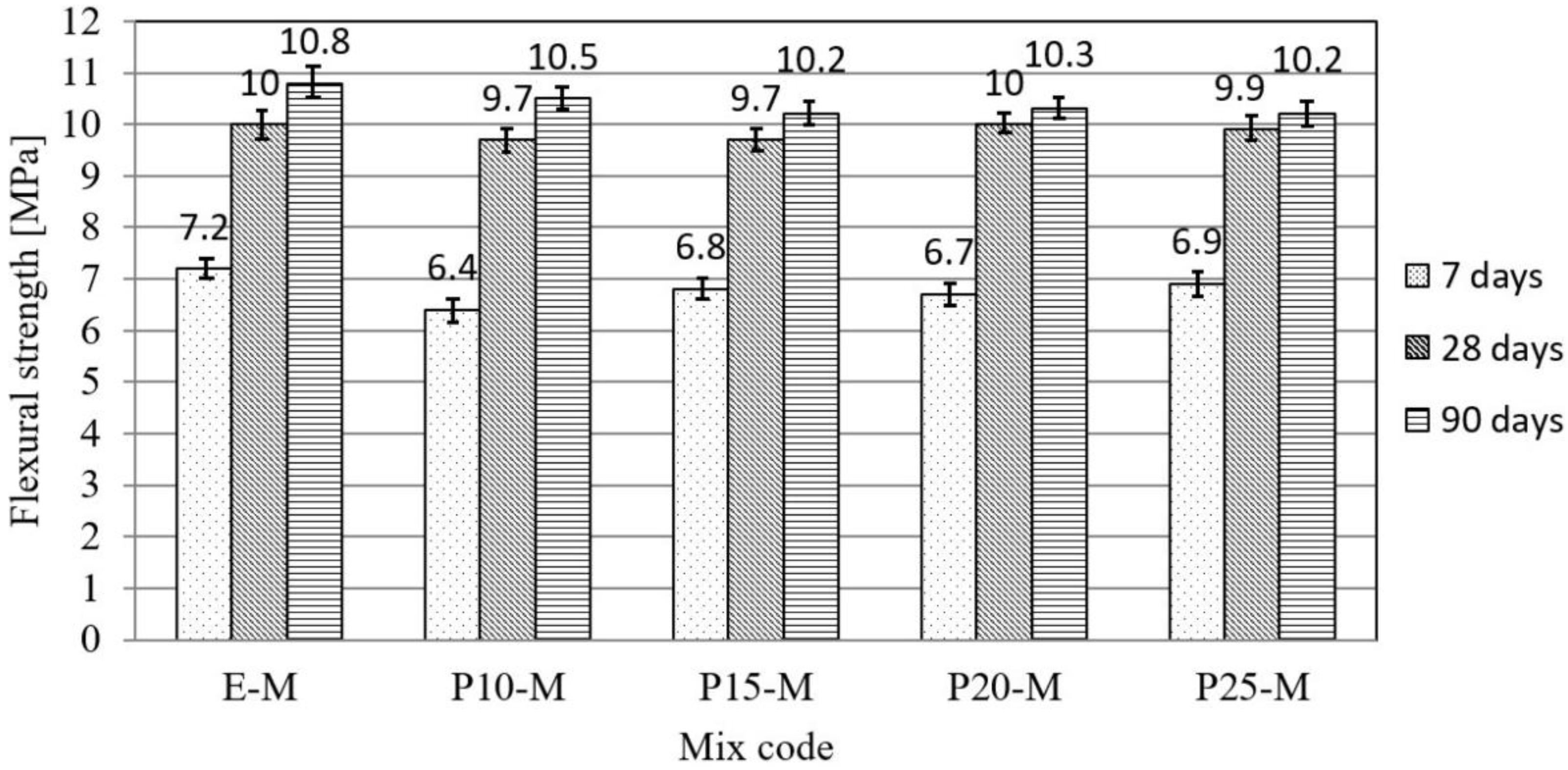
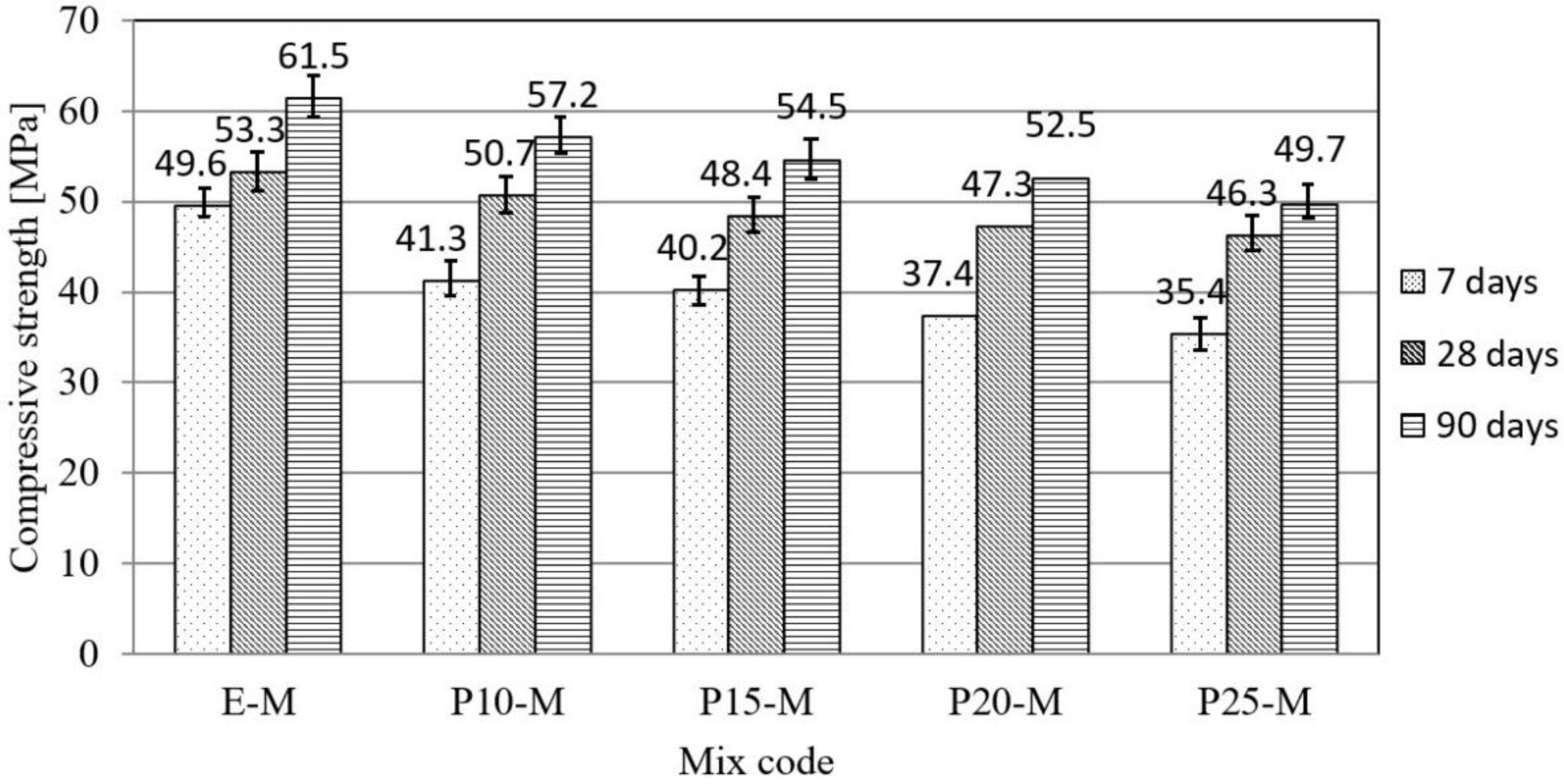
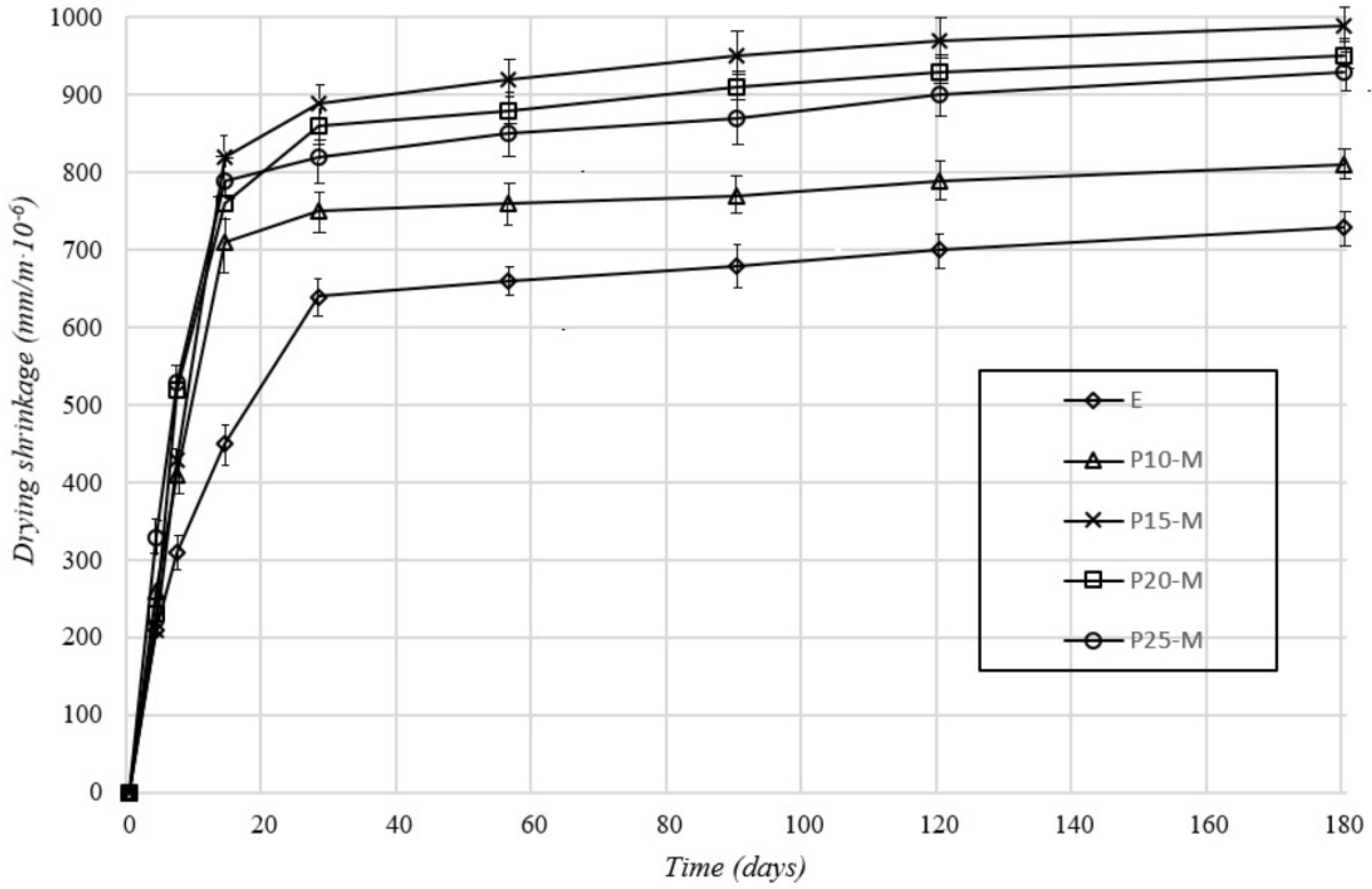
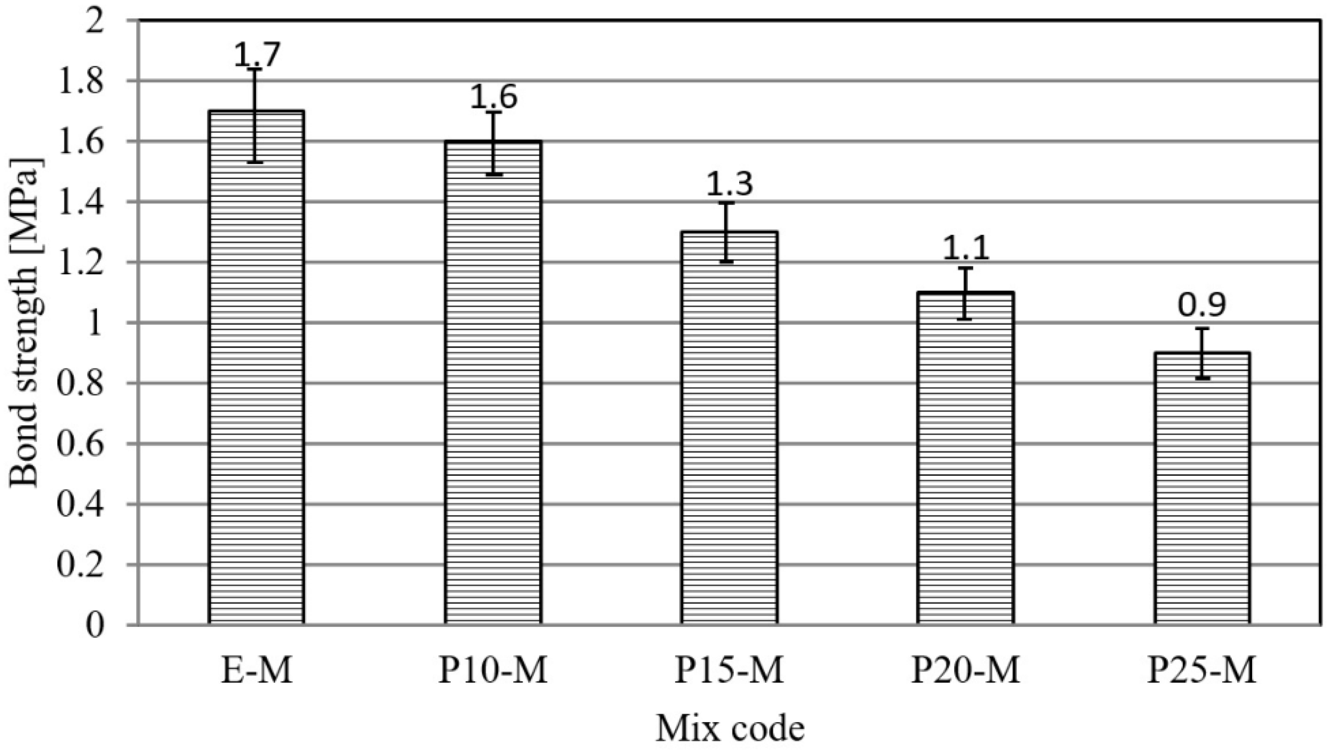
3.1. Physical–Mechanical Characterization of Mortar and Concrete

Results of the physical–mechanical characterization of samples are given in Table 4 and Table 5 and Figure 1, Figure 2, Figure 3, Figure 4, Figure 5 and Figure 6.
When testing the consistency of mortar, the slump of the mortar on a shaking table decreases with the increase in the percentage of cement replaced with slag and silica fumes. The reason is the increased water requirement of slag, which reduces the amount of free water in the mortar mixture, and thus its plasticity. By increasing the content of waste material, the bulk density of mortar in the fresh and hardened states decreases. Possible reasons for such trend were the lower specific mass of slag relative to cement, the increased porosity of the mortar due to a decrease in plasticity, as well as the lower amount of sand in mixtures with waste materials, relative to the reference mixture.
The flexural and compressive strength tests were performed at the mortar specimen age of 7, 28, and 90 days (Figure 1 and Figure 2). Based on the test results, it can be observed that with the increasing cement replacement by waste material, the strength of mortar specimens decreased at an early age (7 days). On the other hand, with increasing age (28 and 90 days) the strength of mortar with the waste material approached the values of the reference mortar. This is attributed to the pozzolanic reaction of slag and silica fumes, which manifested itself at a later stage of hardening [17,18,19,20]. That is the reason that the percentage of possible replacement of cement with waste material was estimated based on strength at 90 days. The decrease in compressive strength was from 7.0% up to 19.2% with a percentage replacement of cement from 10% to 25%. One of the reasons for the decrease in mechanical strengths is the lower density of mortar mixtures in which cement has been replaced by waste materials.
Replacement of cement with slag resulted in an increase in the value of water absorption at atmospheric pressure, while, on the other hand, it contributed to a decrease in the absorption coefficient due to capillary water absorption. However, regardless of the test method, the maximum difference in water absorption values was up to 15%.
Based on the shrinkage measurements results due to the drying of cement mortars, (Figure 3), it can be observed that mortar mixtures with the addition of waste material had higher shrinkage values than the reference mortar, wherein the shrinkage was greater at a later curing stage. The reason for the increased shrinkage is the pozzolanic reaction of slag and silica fumes. Similar trends were observed by researchers for an examination of the influence of glass powder on the properties of cement mortar [19]. It should be mentioned that the highest shrinkage was recorded in the mortar mixture with 15% of cement replacement. This was likely because the porosities of the mortar mixtures, P20-M and P25-M, were higher than the porosity for P15-M, which means that these mixtures had a lower volume of the cement paste shrinking during hardening.
The replacement of cement with waste material had the effect of reducing the adhesion of the mortar to the concrete substrate. With an increase in the percentage of cement replacement, the adhesive strength decreased, with a decrease of 6–47% (Figure 4). The possible reason for the reduction of adhesion in mortars with a higher content of waste material is the lower quantity of free water necessary for the hydration of cement materials in the hardening period.
Based on the results of concrete consistency testing, it can be concluded that as the content of waste material increased, the size of the slump decreased significantly. This was due to the porosity and higher specific surface area (Table 1) of the waste material and its ability to retain water, thereby reducing the amount of free water in the concrete mixture, and thus the consistency [16,21,22]. The content of air entrained into fresh concrete increased with an increasing percentage of cement replacement with waste material. By increasing the content of waste material, the bulk density of concrete in the fresh and hardened states decreased, as in the case of mortar mixtures. This can be ascribed to the higher content of entrained air in fresh concrete and the lower amount of aggregate in mixtures where a partial replacement of cement was performed, and to the lower specific gravity of waste materials in comparison with cement, Table 1.
The flexural strength test was performed at the ages of samples for 28 days (Figure 5). It can be noticed that the flexural strength decreased with the increase in the replacement of cement, and that was compared to the reference concrete in the range from 14 to 26%. Compressive strength was the most significant characteristic of concrete, and it was determined at test specimen ages of 2, 7, 28, and 90 days (Figure 6). Firstly, it was observed that with the increase in cement replacement by waste material, the strengths of concrete specimens decreased at all ages of concrete. In the first 7 days, the highest increase in compressive strength was recorded with the reference mortar, while with increasing age the compressive strength of concrete prepared with waste material approached the reference concrete due to the delayed pozzolanic reaction [23]. The decrease in compressive strength at 90 days was 7.2–21.7% with a percentage replacement of cement of 10–25%. The possible reason for the reduction of the final strength of concrete with the waste material is the lower density of concrete in comparison with the reference concrete due to the higher entrained air content and the lower amount of aggregate.
Generally, the replacement of cement with slag and silica fumes reduced the physical and mechanical properties of mortar and concrete, but cement composites retained the required structural properties. Mechanical strength, and especially compressive strength, were very important parameters for cement composites. If 15–20% was considered an acceptable level of compressive strength decrease, then it can be concluded that, in mortar and concrete production, cement could be replaced by waste material by up to 20%. Additionally, results of the physical–mechanical characterization showed that mortar and concrete materials with 20% of cement replacement may be used as constructional materials in the construction industry.

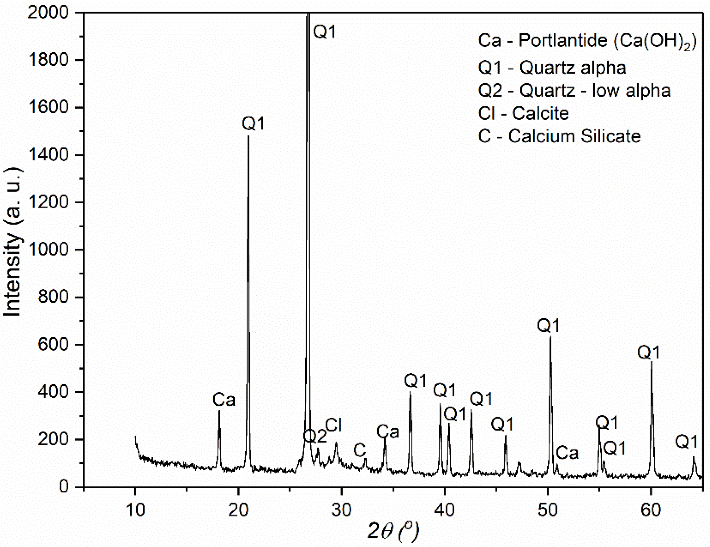
3.2. X-Ray-Structural Diffraction Analysis (XRD) of the Mortar Samples

Since the results of the testing of physical–mechanical properties showed that 20% was the maximal amount of cement which may be replaced by slag and silica fumes in mortar and concrete production, physical–chemical characterization was performed on the hardened mortar sample P20-M (containing cement (17.75%), slag (3.94%), silica fumes (0.49%), river sand (66.54%), water (11.10%) and superplasticizer (0.18%)).
Results of the XRD analysis are shown in Figure 7.
In the investigated sample the presence of the following crystal phases were observed: portlandite (Ca(OH)2), quartz (SiO2), calcite (CaCO3), and calcium silicate-oxide (Ca2SiO4). The most abundant phase was quartz, then portlandite, and calcite, while calcium silicate-oxide was less present. Such composition was expected because portlandite, calcite and calcium silicate-oxide originated from cement, while quartz originated from river sand, silica fumes and slag. Other constituents of starting mortar components were not detected because their spectral bands overlapped with those originating from the most abundant crystalline phases. In the constituents from quartz, alpha-quartz is dominant. For hardened mortar, the crystallinity was high. Additionally, new crystalline phases except those which originated from starting samples were not detected by XRD. However, although this has not been determined in our research, the formation of new phases when waste material was used as a replacement or addition to cement was possible. For example, J. Seo et al. [24] showed that when blast furnace slag and calcium sulfoaluminate cement were mixed, a new phase strätlingite (Ca2Al2SiO7·8H2O) was formed as a consequence of the reaction of aluminum–hydroxide and Ca2SiO4. The same phenomenon was also shown by other authors for steel slag [25] or ground perlite [26]. In order to definitively determine whether new phases had formed, additional methods of physical–chemical characterization were performed.

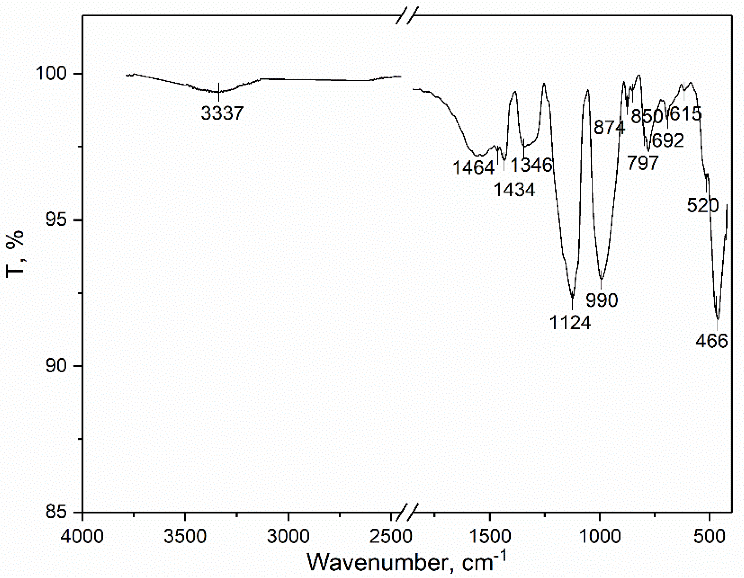
3.3. Infrared Spectroscopy with Fourier Transform (FTIR)

The infrared spectrum of the hardened mortar is given at Figure 8. In the spectrum of the hardened mortar, spectral bands at 3337, 1464, 1434, 1124, 990, 874, 850, 692, 615, 520, and 466 cm−1 are visible. The spectral band at 3337 cm−1 may be assigned to the H–H stretching vibrations due to the presence of the physical-bounded and surface-adsorbed water [27]. The bands at 1464 and 1346 cm−1 are characteristic of and confirmed the presence of Ca(OH)2 [28]. The bands of 1434, 874, and 692 cm−1 are attributed to in- and out-plane bending and asymmetrical stretching vibrations of the O–C–O, respectively, which occur due to the presence of the CaCO3 [29]. The bands at 1100, 797, and 615 cm−1 indicate the presence of the SiO2 and are characteristic of asymmetrical and symmetrical stretching modes (1100, 797 cm−1) and bending mode (615 cm−1) as weak bands [30]. The spectral band at 466 cm-1 originates from Fe-O vibrations due to presence of iron oxide (Table 1) [31,32].
Other spectral bands at 990, 850, and 520 cm−1 are characteristic of the calcium silicate-oxide (Ca2SiO4) [33]. As it may be seen from the spectrum of the hardened mortar sample, only spectral bands of the main constituents detected by the XRD are visible. The spectral bands of the new functional groups, as well as bands of other constituents, are not visible which may be explained with overlapping spectral bands or what may be an indication that new phases are not formed.

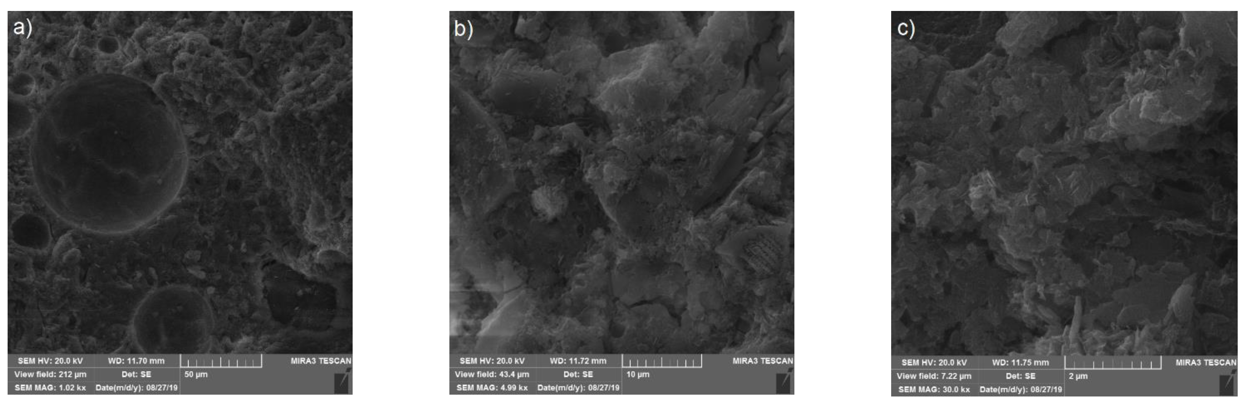
3.4. Scanning Electron Microscopy (SEM) of the Mortar Samples

Results of the scanning electron microscopy (SEM) of the hardened mortar samples (P20-M) are given at Figure 9.
The cementing matrix is a heterogeneous mixture of crystal phases that correspond to minerals in cement or other components in mortar. In a micrograph taken at a magnification of 1.02 k×, ball-shaped, well-defined recesses are visible which are derived from water molecules that have been ejected from the surface by the preparation and hitting of the sample prior to analysis. The micrographs taken at higher magnifications (4.99 and 30.0 k×) show a morphology in which shape and size of the platelets are characteristic of silicate, aluminosilicate and calcium hydroxide samples. The morphology shown by these investigations gives an indication that the applied design of the mortar production leads to the dispersion of cement, slag, silica fumes, river sand and superplasticizer.

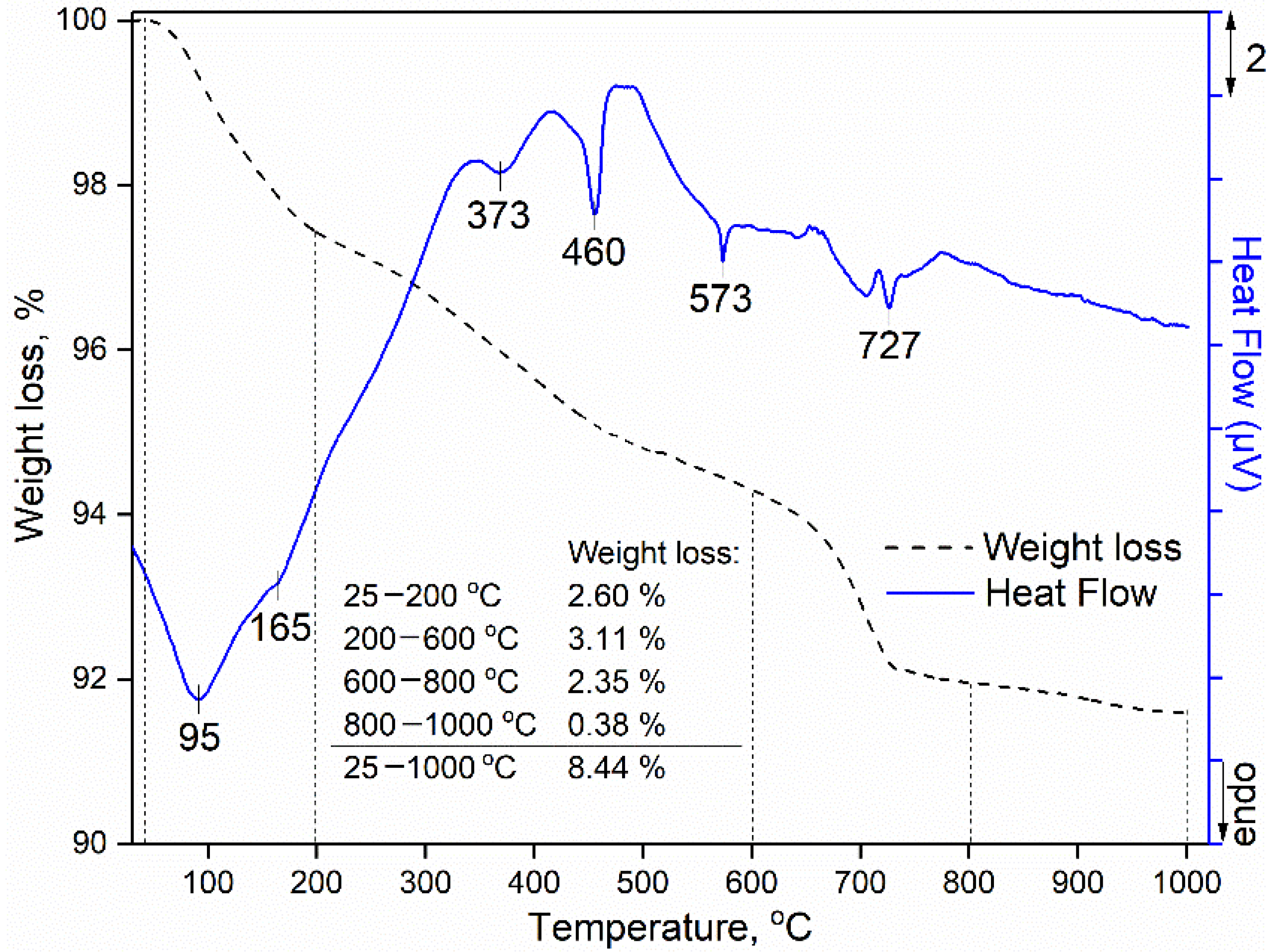
3.5. Thermal Analysis of the Hardened Mortar Samples

Results of the thermal analyses (thermogravimetric and different thermal analysis (TGA-DTA)) of the designed hardened mortar sample with 20% of cement replacement are given in Figure 10.
From the results presented in Figure 10, it may be concluded that thermal analysis confirms the results of XRD and FTIR analysis and peaks characteristic of the phases present to the greatest extent are visible. As it may be seen from Figure 10, on the DTA curve of the investigated sample in the first temperature interval (25–200 °C), two endothermic peaks are visible, at 95 and 165 °C, of which the first one is associated with endothermic reactions such as the dehydration and removal of physically adsorbed water, while the second one originates from the dehydration and decomposition of the hydrates of the silicate-oxides, as well as calcium silicate-oxides [34]. This process has been followed with a weight loss of around 2.60% on the TGA curve. In the second temperature interval (200–600 °C) endothermic peaks are observed at 373, 460, and 573 °C. The peaks at 373 °C and 460 °C originate due to the decomposition of the calcium-hydroxide [34], while the existence of the endothermic peak at 573 °C confirms the presence of quartz (river sand) and or silicate fume (SiO2) [35]. In this temperature interval (200–600 °C) determined mass loss by TG analysis was 3.11%. Weight loss in the third temperature interval (600–800 °C) of 2.35% and the endothermic peak at 727 °C, is caused by the decomposition of the carbonates, which is additional confirmation of the presence of the calcite (CaCO3) in the designed mortar [36].

4. Conclusions

The results presented in this study show that waste slag generated in a heating plant by the combustion of lignite and taken from the Valjevo landfill in Serbia, may, despite being hazardous waste, be used in combination with silica fumes as a partial replacement for cement in the production of mortar and concrete as materials in the construction industry. Results of the physical–mechanical characterization show that maximal possible cement replacement is 20% (17.8% of slag and 2.2% of silica fumes) and for such a ratio, all requirements prescribed by the standards are satisfied.
Physical–chemical characterization is performed on the hardened mortar samples which have the maximal cement replacement (20%).
The results of the XRD analysis show that the following crystal phases are present in the investigated sample: quartz as the most abundant, then portlandite and calcite, while calcium silicate-oxide is less present.
The results of the FTIR and thermal analyses confirm the results of the XRD analysis and only the spectral bands (FTIR) and peaks (TGA/DTA) of the main constituents detected by the XRD are visible, and indicate that new phases are not formed.
The results of SEM analysis indicate that the model of mortar production applied leads to the dispersion of cement, slag, silica fumes, river sand and superplasticizer.

Author Contributions

M.K. conceived and designed the experiments, wrote the paper, and contributed to all experiments and the analyzing of the obtained results; N.R. performed physical–mechanical measurements and contributed to analyzing the results; M.S., J.G. and I.R. participated in SEM and thermal analyses and analyzed the results; A.N. and S.P. contributed in XRD measurements. All authors have read and agreed to the published version of the manuscript.

Funding

This research received no external funding.

Data Availability Statement

The study do not report any data.

Acknowledgments

This work was supported by the Ministry of Education, Science and Technological Development of the Republic of Serbia through the realization of research themes 1702103 and 1702105.

Conflicts of Interest

The authors declare no conflict of interest.

References

  1. Zhang, F.; Xing, Y.; Chang, G.; Yang, Z.; Cao, Y.; Gui, X. Enhanced lignite flotation using interfacial nanobubbles based on temperature difference method. Fuel 2021, 293, 120313. [Google Scholar] [CrossRef]
  2. Zhao, H.Y.; Li, Y.H.; Song, Q.; Liu, S.C.; Yan, J.; Ma, Q.X.; Zhu, X. Investigation on the thermal behavior characteristics and products composition of four pulverized coals: Its potential applications in coal cleaning. Int. J. Hydrogen Energy 2019, 44, 23620–23638. [Google Scholar] [CrossRef]
  3. Xia, W.C.; Xie, G.Y.; Peng, Y.L. Recent advances in beneficiation for low rank coals. Powder Technol. 2015, 277, 206–221. [Google Scholar] [CrossRef]
  4. American Geosciences Institute. Available online: https://www.americangeosciences.org/critical-issues/faq/what-are-the-dierent-types-of-coal (accessed on 30 May 2021).
  5. Yu, J.L.; Tahmasebi, A.; Han, Y.N.; Yin, F.K.; Li, X.C. A review on water in low rank coals: The existence, interaction with coal structure and effects on coal utilization. Fuel Process Technol. 2013, 106, 9–20. [Google Scholar] [CrossRef]
  6. Available online: https://iea.blob.core.windows.net/assets/c40f0317-f8e6-4f00-b183-27a24c7b6a8f/Coal_Information_2019_Overview.pdf (accessed on 30 May 2021).
  7. Aydin, S.; Baradan, B. Efect of pumice and fly ash incorporation on high temperature resistance of cement based mortars. Cem. Concr. Res. 2007, 37, 988–995. [Google Scholar] [CrossRef]
  8. European List of Waste, the Classification of Waste Based on: The European List of Waste (Commission Decision 2000/532/EC—Consolidated Version) and Annex III to Directive 2008/98/EC (Consolidated Version). Available online: http://data.europa.eu/eli/dec/2000/532/2015-06-01 (accessed on 25 May 2021).
  9. Berryman, C.; Zhu, J.; Tadros, M. High-percentage replacement of cement with fly ash for reinforced concrete pipe. Cem. Concr. Res. 2005, 35, 1088–1091. [Google Scholar] [CrossRef]
  10. Ray, T.; Mohanta, N.R.; Kumar, M.H.; Macharyulu, I.S.; Samantaray, S. Study of effect of temperature on behavior of alkali activated slag concrete. Mater. Today Proc. 2021, 43, 1352–1357. [Google Scholar] [CrossRef]
  11. Czop, M.; Łaźniewska-Piekarczyk, B. Use of Slag from the Combustion of Solid Municipal Waste as a Partial Replacement of Cement in Mortar and Concrete. Materials 2020, 13, 1593. [Google Scholar] [CrossRef] [Green Version]
  12. Rivera, J.F.; Cristelo, N.; Fernández-Jiménez, A.; de Gutiérrez, R.M. Synthesis of alkaline cements based on fly ash and metallurgic slag: Optimisation of the SiO2/Al2O3 and Na2O/SiO2 molar ratios using the response surface methodology. Constr. Build. Mater. 2019, 213, 424–433. [Google Scholar] [CrossRef]
  13. Zhang, Y.; Zhang, S.; Ni, W.; Yan, Q.; Gao, W.; Li, Y. Immobilisation of high-arsenic-containing tailings by using metallurgical slag-cementing materials. Chemosphere 2019, 223, 117–123. [Google Scholar] [CrossRef]
  14. Tabelin, C.B.; Villacorte-Tabelin, M.; Park, I.; Phengsaart, T.; Jeon, S.; Hiroyoshi, N. Copper and critical metals production from porphyry ores and E-wastes: A review of resource availability, processing/recycling challenges, socio-environmental aspects, and sustainability issues. Resour. Conserv. Recycl. 2021, 170, 105610. [Google Scholar] [CrossRef]
  15. Opiso, E.M.; Tabelin, C.B.; Maestre, C.V.; Aseniero, J.P.J.; Park, I.; Illacorte-Tabelin, M. Synthesis and characterization of coal fly ash and palm oil fuel ash modified artisanal and small-scale gold mine (ASGM) tailings based geopolymer using sugar mill lime sludge as Ca-based activator. Heliyon 2021, 7, e06654. [Google Scholar] [CrossRef]
  16. Nedeljković, A.; Stojmenović, M.; Gulicovski, J.; Ristić, N.; Milićević, S.; Krstić, J.; Kragović, M. Waste Slag from Heating Plants as a Partial Replacement for Cement in Mortar and Concrete Production. Part I—Physical–Chemical and Physical–Mechanical Characterization of Slag. Minerals 2020, 10, 992. [Google Scholar]
  17. Cheah, C.B.; Ramli, M. Mechanical strength, durability and drying shrinkage ofstructural mortar containing HCWA as partial replacement of cement. Constr. Build. Mater. 2012, 30, 320–329. [Google Scholar] [CrossRef]
  18. Garcia, M.D.L.; Sousa-Coutinho, J. Strength and durability of cement with forest waste bottom ash. Constr. Build. Mater. 2013, 2013 41, 897–910. [Google Scholar] [CrossRef]
  19. Grdić, D.; Ristić, N.; Topličić-Ćurčić, G.; Đorđević, D.; Krstić, N. Effects of addition of finely ground CRT glass on the properties of cement paste and mortar. Građevinar 2020, 72, 1–10. [Google Scholar]
  20. Mafalda, A.; Sousa-Coutinho, J. Durability of mortar using waste glass powder as cement replacement. Constr. Build. Mater 2012, 36, 205–215. [Google Scholar]
  21. Chavan, S.P.; Salokhe, S.A.; Nadagauda, P.A.; Patil, S.T.; Mane, K.M. An investigational study on properties of concrete produced with industrial waste red mud. Mater. Today Proc. 2021, 42, 733–738. [Google Scholar] [CrossRef]
  22. Anirudh, M.; Rekha, K.S.; Venkatesh, C.; Nerella, R. Characterization of red mud based cement mortar; mechanical and microstructure studies. Mater. Today Proc. 2021, 43, 1587–1591. [Google Scholar] [CrossRef]
  23. Sadiqul, I.G.M.; Rahman, M.H.; Kazi, N. Waste glass powder as partial replacement of cement for sustainable concrete practice. Int. J. Sustain. Built Environ. 2017, 6, 37–44. [Google Scholar]
  24. Seo, J.; Kim, S.; Park, S.; Yoon, H.N.; Lee, H.K. Carbonation of calcium sulfoaluminate cement blended with blast furnace slag. Cem. Concr. Compos 2021, 118, 103918. [Google Scholar] [CrossRef]
  25. Liao, Y.; Jiang, G.; Wang, K.; Al Qunaynah, S.; Yuan, W. Effect of steel slag on the hydration and strength development of calcium sulfoalumi-nate cement. Constr. Build. Mater. 2020, 265, 120301. [Google Scholar] [CrossRef]
  26. Sengül, K.; Erdogan, S.T. Influence of ground perlite on the hydration and strength develop-ment of calcium aluminate cement mortars. Constr. Build. Mater. 2021, 266, 120943. [Google Scholar] [CrossRef]
  27. Mojet, B.L.; Ebbesenz, S.D.; Lefferts, L. Light at the interface: The potential of attenuated total reflection infrared spectroscopy for understanding heterogeneous catalysis in water. Chem. Soc. Rev. 2010, 39, 4643–4655. [Google Scholar] [CrossRef] [PubMed]
  28. Cavallaro, G.; Danilushkina, A.A.; Evtugyn, V.G.; Lazzara, G.; Milioto, S.; Parisi, F.; Rozhina, E.V.; Fakhrullin, R.F. Halloysite Nanotubes: Controlled Access and Release by Smart Gates. Nanomaterials 2017, 7, 199. [Google Scholar] [CrossRef] [PubMed]
  29. Abdolmohammadi, S.; Siyamak, S.; Ibrahim, N.A.; Yunus, W.M.Z.W.; Rahman, M.Z.A.; Azizi, S.; Fatehi, A. Enhancement of Mechanical and Thermal Properties of Polycaprolactone/Chitosan Blend by Calcium Carbonate Nanoparticles. Int. J. Mol. Sci. 2012, 13, 4508–4522. [Google Scholar] [CrossRef] [PubMed]
  30. Tran, T.N.; Pham, T.V.A.; Le, M.L.P.; Nguyen, T.P.T.; Tran, V.M. Synthesis of amorphous silica and sulfonic acid functionalized silica used as reinforced phase for polymer electrolyte membrane. Adv. Nat. Sci. Nanosci. Nanotechnol. 2013, 4, 045007. [Google Scholar] [CrossRef] [Green Version]
  31. Tabelin, C.B.; Veerawattananun, S.; Ito, M.; Hiroyoshi, N.; Igarashi, T. Pyrite oxidation in the presence of hematite and alumina: I. Batch leaching experiments and kinetic modeling calculations. Sci. Total Environ. 2017, 580, 687–698. [Google Scholar] [CrossRef]
  32. Park, I.; Tabelin, C.B.; Magaribuchi, K.; Seno, K.; Ito, M.; Hiroyoshi, N. Suppression of the release of arsenic carrier-microencapsulation from arsenopyrite by using Ti-catechol complex. J. Hazard. Mater. 2018, 344, 322–332. [Google Scholar] [CrossRef]
  33. Handke, M.; Ptak, W. IR and Raman studies of the stabilization beta-Ca2SiO4. Ceramurgia international 1978, 4, 75. [Google Scholar] [CrossRef]
  34. Zhang, G.; Li, Z.; Zhang, L.; Shang, Y.; Wang, H. Experimental research on drying control condition with minimal effect on concrete strength. Constr. Build. Mater 2017, 135, 194–202. [Google Scholar] [CrossRef] [Green Version]
  35. Schelz, J.P. The detection of quartz in clay minerals by differential thermal analysis. Thermochimicu Acta 1976, 15, 17-B. [Google Scholar] [CrossRef]
  36. Parvan, M.-G.; Voicu, G.; Badanoiu, A.-I.; Nicoara, A.-I.; Vasile, E. CO2 Sequestration in the Production of Portland Cement Mortars with Calcium Carbonate Additions. Nanomaterials 2021, 11, 875. [Google Scholar] [CrossRef] [PubMed]
Figure 1. Flexural strength of mortar mixtures.
Minerals 11 00925 g001
Figure 2. Compressive strength of mortar mixtures.
Minerals 11 00925 g002
Figure 3. Drying shrinkage development of mortar mixtures.
Minerals 11 00925 g003
Figure 4. Adhesion between mortar and a concrete substrate.
Minerals 11 00925 g004
Figure 5. Flexural strength of concrete mixtures (28 days).
Minerals 11 00925 g005
Figure 6. Compressive strength of concrete mixtures.
Minerals 11 00925 g006
Figure 7. XRD analysis of the hardened mortar sample P20-M.
Minerals 11 00925 g007
Figure 8. FTIR spectrum of the hardened mortar sample P20-M.
Minerals 11 00925 g008
Figure 9. SEM micrographs of the hardened mortar sample P20-M taken with three different magnifications: (a) 1.02 k×; (b) 4.99 k× and (c) 30.0 k×.
Minerals 11 00925 g009
Figure 10. Thermal analysis of the hardened mortar sample P20-M. --- TGA; DTA.
Minerals 11 00925 g010
Table 1. The physical–chemical, chemical and mineralogical properties of the used cement, slag and silica fumes [16].
Properties/ContentCementSlagSilica Fume
ρ, g/cm33.152.242.21
SBET, m2/g1.2225.0028.14
SiO2, %21.6221.2093.60
Fe2O3, %2.6010.810.21
Al2O3, %7.0015.700.27
CaO, %60.166.320.05
MgO, %2.342.500.05
SO3, %2.551.780.80
Na2O, %0.332.670.23
K2O, %0.660.630.50
P2O5, %-0.036-
LOI, %2.6837.452.40
Mineral compositionbrownmillerite, calcium silicate oxide, calcite, larnite, magnesium silicate, calcium hydroxidequartz, olivine, magnetite, pyrite, tridymite, feldsparsquartz
Table 2. Mix proportion of mortar for one series of samples.
ComponentE-MP10-MP15-MP20-MP25-M
Cement [g (cm3)]450.00 (142.86)402.34 (127.73)378.73 (120.23)355.27 (112.78)331.96 (105.38)
Slag [g (cm3)]-39.79 (17.76)59.48 (26.55)79.05 (35.29)98.48 (43.96)
Silica fumes [g (cm3)]-4.90 (2.23)7.36 (3.33)9.77 (4.42)12.18 (5.51)
River sand 0/2 mm [g (cm3)]1350.00 (517.24)1341.14 (513.85)1336.70 (512.15)1332.26 (510.44)1327.83 (508.75)
Water [g]225.00 (225.00)223.52 (223.52)222.78 (222.78)222.04 (222.04)221.30 (221.30)
Superplasticizer [g (cm3)]3.60 (3.30)3.58 (3.28)3.56 (3.27)3.55 (3.26)3.54 (3.25)
SUM [g (cm3)]2028.60 (888.40)2015.29 (888.37)2008.62 (888.24)2001.94 (888.24)1995.28 (888.16)
Table 3. Mix proportion of concrete mixtures for 1 m3 of concrete.
ComponentE-CP10-CP15-CP20-CP25-C
Cement [kg (m3)]375.00 (0.119)336.32 (0.107)316.78 (0.101)297.32 (0.094)277.67 (0.088)
Slag [kg]-33.16 (0.015)49.65 (0.022)66.08 (0.029)82.34 (0.037)
Silica fumes [kg (m3)]-4.15 (0.002)6.21 (0.003)8.26 (0.004)10.30 (0.005)
River sand 0/4 mm [kg (m3)]752.00 (0.287)748.26 (0.286)746.77 (0.285)745.29 (0.284)743.08 (0.284)
Crushed aggr. (4/8 mm) [kg (m3)]432.00 (0.149)429.85 (0.149)429.00 (0.148)428.15 (0.148)426.88 (0.148)
Crushed aggr. (8/16 mm) [kg (m3)]692.00 (0.239)688.56 (0.238)687.19 (0.238)685.83 (0.237)683.79 (0.237)
Water [kg (m3)]182.25 (0.182)181.34 (0.181)180.98 (0.181)180.62 (0.181)180.09 (0.180)
Superplasticizer [kg (m3)]3.75 (0.003)3.73 (0.003)3.72 (0.003)3.72 (0.003)3.71 (0.003)
SUM2437 (0.981)2425.37 (0.981)2420.31 (0.981)2415.26 (0.981)2407.86 (0.981)
Assumed air content~2%~2%~2%~2%~2%
ComponentE-CP10-CP15-CP20-CP25-C
Cement [kg (m3)]375.00 (0.119)336.32 (0.107)316.78 (0.101)297.32 (0.094)277.67 (0.088)
Slag [kg]-33.16 (0.015)49.65 (0.022)66.08 (0.029)82.34 (0.037)
Silica fumes [kg (m3)]-4.15 (0.002)6.21 (0.003)8.26 (0.004)10.30 (0.005)
River sand 0/4 mm [kg (m3)]752.00 (0.287)748.26 (0.286)746.77 (0.285)745.29 (0.284)743.08 (0.284)
Crushed aggr. (4/8 mm) [kg (m3)]432.00 (0.149)429.85 (0.149)429.00 (0.148)428.15 (0.148)426.88 (0.148)
Crushed aggr. (8/16 mm) [kg (m3)]692.00 (0.239)688.56 (0.238)687.19 (0.238)685.83 (0.237)683.79 (0.237)
Water [kg (m3)]182.25 (0.182)181.34 (0.181)180.98 (0.181)180.62 (0.181)180.09 (0.180)
Superplasticizer [kg (m3)]3.75 (0.003)3.73 (0.003)3.72 (0.003)3.72 (0.003)3.71 (0.003)
SUM2437 (0.981)2425.37 (0.981)2420.31 (0.981)2415.26 (0.981)2407.86 (0.981)
Assumed aer content~2%~2%~2%~2%~2%
Table 4. Physical properties of fresh and hardened mortar.
ParameterUnitE-MP10-MP15-MP20-MP25-M
Consistency: by flow tablemm205 ± 7.9187 ± 7.2169 ± 7.5152 ± 6.4136 ± 6.0
Bulk density of fresh mortarkg/m32248 ± 12.32215 ± 10.42186 ± 12.02158 ± 9.12126 ± 10.9
Dry bulk density of hardened mortarkg/m32176 ± 11.52132 ± 12.42073 ± 12.02055 ± 9.72031 ± 10.2
Water absorption (water absorption at atmospheric pressure)% (m/m)7.1 ± 0.197.5 ± 0.158.2 ± 0.178.1 ± 0.147.9 ± 0.18
Water absorption (coefficient due to capillary
action of hardened mortar): for mortars other than renovation mortars
m2 × min−0.50.25 ± 0.0160.21 ± 0.0180.23 ± 0.0140.23 ±0.0200.19 ±0.015
Water absorption (coefficient due to capillary
action of hardened mortar): for renovation mortars
kg/m27.65 ± 0.1045.19 ± 0.1225.88 ± 0.1345.67 ± 0.1155.11 ± 0.128
Table 5. Physical properties of fresh and hardened concrete.
ParameterUnitE-CP10-CP15-CP20-CP25-C
Consistency: slump testmm240 ± 12.3180 ± 11.6140 ± 10.490 ± 8.220 ± 6.5
Air content in fresh concrete%2.5 ± 0.253.4 ± 0.324.1 ± 0.345.0 ± 0.335.6 ± 0.35
Density of fresh concretekg/m32473 ± 17.72432 ± 16.22369 ± 15.52349 ± 16.02341 ± 14.3
Density of hardened concrete (water-saturatedkg/m32465 ± 16.92422 ± 17.52360 ± 14.72338 ± 15.42331 ± 15.0
Publisher’s Note: MDPI stays neutral with regard to jurisdictional claims in published maps and institutional affiliations.

