Article

Starting Modes of Bi-Directional Plasma Thruster Utilizing Krypton

by
Andrei I. Shumeiko
1,2,
Victor D. Telekh
2 and
Sergei V. Ryzhkov
3,*
1
Advanced Propulsion Systems LLC, 7 Nobel Street, 2/35/5, 121205 Moscow, Russia
2
Department of Plasma Power Plants, Bauman Moscow State Technical University, 2-ya Baumanskaya Street, 5/1, 105005 Moscow, Russia
3
Department of Thermal Physics, Bauman Moscow State Technical University, 2-ya Baumanskaya Street, 5/1, 105005 Moscow, Russia
*
Author to whom correspondence should be addressed.
Symmetry 2023, 15(9), 1705; https://doi.org/10.3390/sym15091705
Submission received: 29 July 2023 / Revised: 3 September 2023 / Accepted: 5 September 2023 / Published: 6 September 2023
(This article belongs to the Special Issue Symmetry in Physics of Plasma Technologies II)

Abstract

:
Multidirectional plasma thrusters are of particular interest for dynamic space missions due to the adjustability of their integral characteristics. One type of multidirectional plasma thrusters is -directional, consisting of a symmetric electromagnetic system surrounding the gas discharge chamber, capable of generating a propulsion minimum in two directions. The experimental results of this study of the starting modes of a multidirectional plasma thruster utilizing krypton as propellant are reported. The thruster is placed in a vacuum chamber. The magnetic field strength is adjusted in the range of 35 to 400 G in peaks. The current of 13.56 MHz frequency applied to the antenna is regulated in the range of 0 to 25 A. The diameter of the orifices is varied in the range of 3 to 10 mm. In contrast to the unidirectional electrodeless plasma thruster, the radiofrequency breakdown threshold of the multidirectional plasma thruster decreases with increasing static magnetic field due to the symmetry of the magnetic system and the gas discharge chamber. The influence of the magnetic field on the radiofrequency breakdown threshold in the multidirectional plasma thruster is shown theoretically by the classical diffusion theory and ponderomotive effects, and discussed in the electron circulation hypothesis.

1. Introduction

The new leap forward in the development of electric propulsion systems (EPSs) has been caused by the concepts of all-electric spacecraft [1,2]. In these concepts, spacecraft are assumed to contain only plasma-based propulsion systems (PSs) without any chemical thrust-generating technologies. In addition, some researchers have gone further and proposed the use of a single thruster head to generate propulsion in multiple directions [3].
The multidirectional plasma thruster may be a game changer in the transition from static to dynamic space missions. Currently, satellites equipped with unidirectional thrusters require incremental attitude corrections to change orbital position. That is, a satellite with a conventional thruster changes its attitude to change the direction of the propulsion. Such orbital corrections take time and result in propellant and power losses. Time can be especially critical for a variety of space missions, including remote sensing, data retransmission, observation of surrounding space objects, protection of a satellite from surrounding hazards, etc., not to mention debris avoidance, which can become a significant issue in inner space. Nevertheless, the overall maneuverability of a spacecraft can be increased by using multidirectional plasma thrusters. A satellite equipped with a multidirectional plasma thruster for interorbital transfer will be moved by a propulsion system capable of changing its direction without incremental attitude correction. This means that the spacecraft can be moved between orbital positions more quickly, consuming less power and propellant for a given maneuver in space compared to a conventional unidirectional PS. One of the most promising technologies for thrusters that are capable of generating propulsion in multiple directions is electrodeless plasma thrusters [4,5,6,7,8,9,10,11,12,13,14,15,16,17,18,19,20]. Electrodeless plasma thrusters are based on sources that typically consist of a gas discharge chamber, a magnetic system, and an antenna with a high-frequency (HF), radiofrequency (RF), or microwave (mw) power supply.
Recently, several concepts of multidirectional plasma thrusters and thruster heads based on them have been proposed [21,22,23,24,25]. The most mature thruster heads, Hall-effect and ion, are proposed to have thrust vectoring capability by means of sectioned anodes for Hall-effect thrusters [21] and sectioned ion optical systems for ion thrusters [22]. In 2018, Takahashi et al. proposed the electrodeless plasma thruster with a bi-directionality of plasma flow [5]. Later, plasma thrusters capable of generating plasma flows in six directions [3] and more [2] were proposed by Shumeiko et al.
The startup of any plasma thruster includes the step of gas decomposition of the propellant. The startup of the most mature conventional electrostatic plasma thrusters, such as Hall-effect and gridded ion thrusters, is fraught with difficulties. For example, the glow discharge inherent in Hall-effect thrusters can be ignited in the narrow range of modes (determined by the mass flow rate and the potential difference across the channel). This narrow range is caused by the stability region of the glow discharge. The start of gridded ion thrusters can be initiated by several techniques—the mass flow rate and power increase for a short time, or the attraction of externally generated electrons inside the gas discharge chamber. In the latter case, the positive potential is applied to the grids, which acts to attract electrons generated by the cathode neutralizer into the gas discharge chamber, while after the breakdown, the grids should change their potential to pull ions out of the chamber. However, the main problem with the startup of conventional electrostatic plasma thrusters is the time required to heat up the most commonly used cathode-neutralizers (based on tungsten or lanthanum hexaboride). The heating time can limit the ability of conventional thrusters to be used for some space mission objectives, including observation of surrounding space objects and protection of a satellite from surrounding hazards. In addition, cathode neutralizers can only be turned on a limited number of times, which is critical for dynamic space missions that require frequent propulsion. While the former heating problem can be solved by using the heaterless cathode-neutralizers, the latter problem still exists.
In electrodeless plasma thrusters, discharges are initiated by alternating electric fields. The electrodeless configuration and alternating fields eliminate the thruster startup issues critical to dynamic space missions associated with the narrow range of startup modes for stable operation, grid potential change, and cathode-neutralizers. However, electrodeless plasma thruster startup has its own peculiarities.
First, it is known that electrodeless plasma thrusters can suffer from abrupt changes and hysteresis effects in the plasma characteristics [2,26,27,28,29]. The abrupt changes in the plasma characteristics and hysteresis effects can lead to complicated controllability of the exhausted plasma plume characteristics, which can result, for example, in difficult controllability of the thruster integral characteristics—thrust and specific impulse [2]. The hysteresis effects can occur during the change of the power-to-plasma, the magnetic field magnitude, the propellant flow rate, etc., while the change of these characteristics is inherent during the start of the EPS [2]. Therefore, it is important to start the electrodeless plasma thruster from the mode—including the level of power-to-plasma, magnetic field geometry and magnitude, propellant flow rate, gas discharge chamber pressure, and pressure difference—that is suitable for producing the exhausted plasma flow with the required characteristics. Second, gas breakdown for multidirectional configurations of electrodeless plasma thrusters has not been reported. RF gas breakdown occurring in unidirectional electrodeless plasma thrusters is a well-studied phenomenon. There are several studies in the field of RF breakdown in low-pressure gases in the frequency range of 1–100 MHz [30,31,32,33,34,35,36,37]. Kihara [30] theoretically studied RF breakdown for flat parallel electrode capacitively coupled plasma (CCP) sources. Lisovskiy et al. [31] studied RF breakdown in CCP sources with the addition of steady electric fields. Boswell et al. [32] studied RF breakdown in inductively coupled plasma (ICP) sources. Later, Radmilovic-Radjenovic et al. [33,34] theoretically showed RF breakdown in an ICP source with an externally applied magnetic field. Radmilovic-Radjenovic’s theoretical equations show that within the increase in the static magnetic field, electrical breakdown occurs. Wiebold et al. reported that there are conditions—the magnitude of the externally applied magnetic field and the pressure inside the gas discharge chamber—in which it is not possible to initiate RF discharge [35]. At the same time, the multidirectional plasma thrusters differ significantly from the unidirectional ones in that they have multiple orifices and different directions of the magnetic field within them, which can affect the electron paths during the breakdown process, and the theory and results reported for the unidirectional electrodeless plasma thrusters may be inaccurate.
In this research, the starting modes of one of the multidirectional plasma thrusters—the bi-directional one—are studied by varying several parameters—the magnitude of the magnetic field, the propellant flow rate, and the diameter of the orifices at the ends of the open-ended gas discharge chamber.
In the following, Section 2, the technical description of the studied thruster is presented. In Section 3, the testing facility is described and the methodology is discussed. In Section 4, the experimental results and discussion are presented. Section 5 presents the conclusion.

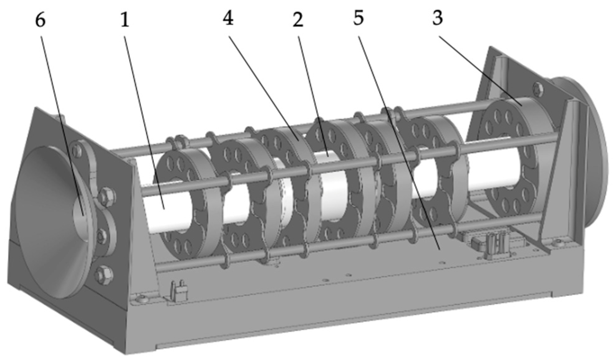
2. Bi-Directional Plasma Thruster

In this research, a bi-directional plasma source that is capable of generating a plasma flow in at least two directions is studied. The tested bi-directional plasma thruster consists of an open-ended cylindrical gas discharge chamber made of monocrystalline alumina, an array of electromagnets (the number of electromagnets is 13) surrounding the chamber, an antenna, and a shield surrounding the antenna (see Figure 1).
The thruster gas discharge chamber is a monocrystalline alumina cylinder that is 190 mm long, 20 mm in outer diameter, and 16 mm in inner diameter. At the open ends of each chamber, orifices can be placed. One of the main features of the magnetic system is the ability to control the direction of the magnetic field, which allows control of the direction of the plasma plume emitted from the source. The magnetic nozzles at each end of the gas discharge chamber consist of two independent electromagnets. This feature allows profiling of the magnetic field at the outlet of the source to collimate the exhausted plasma flow.
The antenna is a half-turn helical antenna with an addition of five turn coils on each side of the antenna. The length of the antenna is 45 mm. The antenna is surrounded by a shield to increase the energy transfer from the antenna to the plasma. Insight to this phenomenon was first reported by Takahashi et al. [38].
The thruster has two gas inlets—CH1 and CH2 (CH is an abbreviation of the word channel). Each gas inlet is located closer to the open ends of the source chambers. The gas inlet CH1 is closer to the magnetic nozzle consisting of electromagnets 1 and 2. The gas inlet CH2 is closer to the magnetic nozzle consisting of electromagnets 12 and 13. The propellant, in this study krypton (Kr), is injected into the gas discharge chamber through the gas inlet closer to the side of the gas discharge chamber from which the thrust is to be generated. Insight into the enhancement of specific thrust through downstream propellant injection was first reported by Takahashi et al. [39].
In this study, there is no change in the configuration of the static magnetic field, but there is a change in the magnitude of the field. In the experiments, all the electromagnets are supplied with the same current in the range of 0.5–5 A. The current direction is the same for electromagnets 2–13. The current direction in electromagnet 1 is opposite to the current direction that is in electromagnets 2–13. The set of electromagnets is connected to the power supply with shielded cables. The electromagnets are connected independently, which makes it possible to adjust the current and the current direction for each electromagnet. The measured magnetic field profile along the gas discharge chamber of the thruster and the simulated 2D distribution of the magnetic flux density at a current of 5 A in the electromagnets are shown in Figure 2 and Figure 3, respectively. The magnetic field measurements (the data are shown in Figure 2) are made using the AlphaLab GM2 gaussmeter. The simulated data shown in Figure 3 were generated using COMSOL Multiphysics. The electromagnets in the simulation are their 3D representation. The electromagnets in the simulation are filled with the real number of cable turns. The current is set to 5 A. The result is obtained by selecting the Magnetic flux density function in the simulation tool.
The reference magnetic field used to determine the modes of RF discharge breakdown modes is considered to be in the central region of the gas discharge chamber because this is where the alternating electric field generated by the antenna is at its maximum.
The studied bi-directional plasma thruster utilizing Kr as a propellant is reported to be capable of generating thrust in the range of 0.5 to 7 mN and specific impulse up to 900 s, while consuming up to 125 W of power at maximum [16].

3. Testing Facility and Methodology
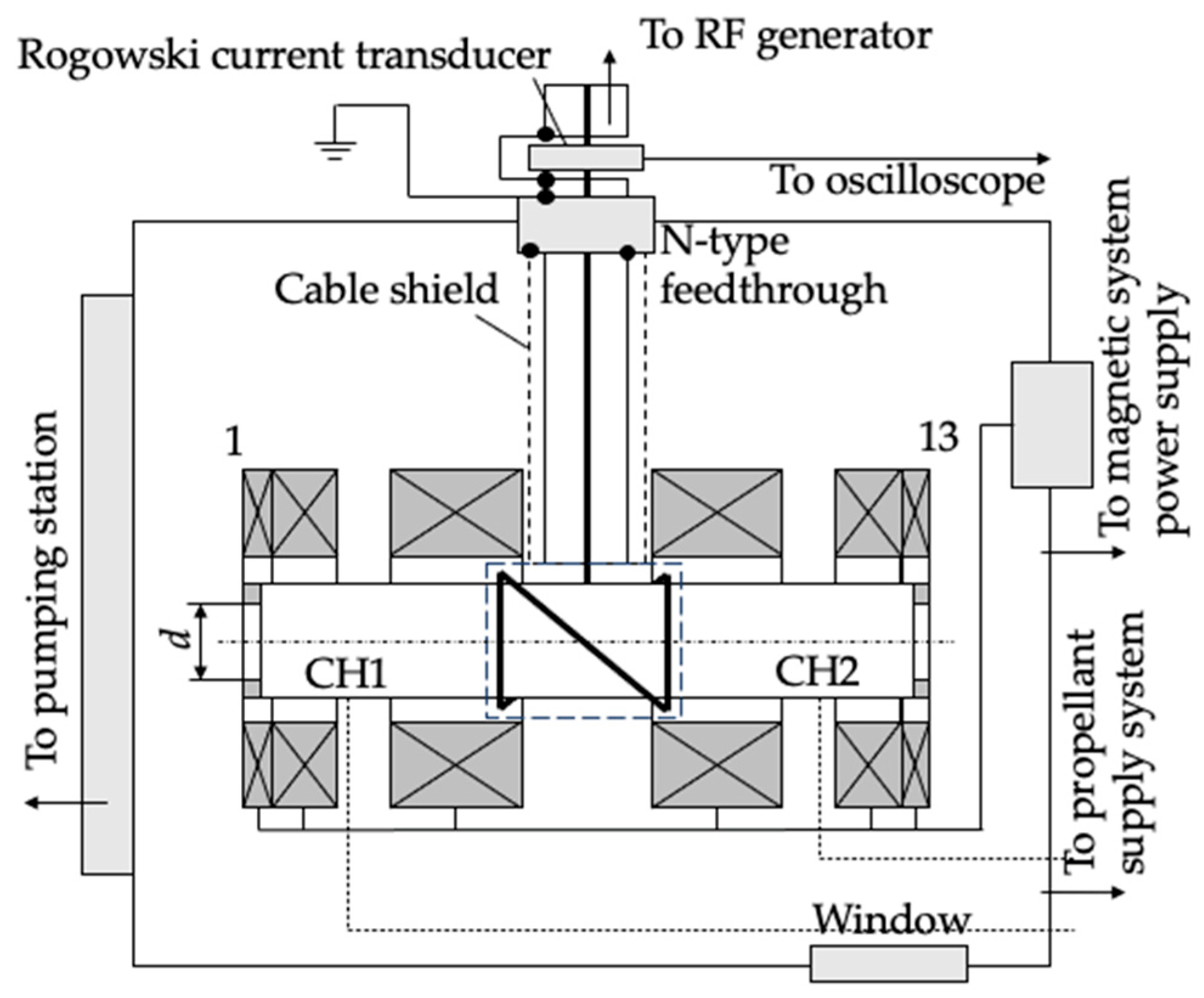
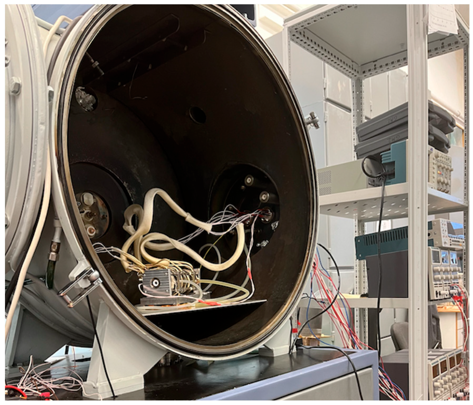
The test bench, RF equipment, gas feedthrough features, and methodology for the experiments are described in Section 3.1, Section 3.2, Section 3.3 and Section 3.4, respectively.

3.1. Test Bench

The experimental setup scheme is shown in Figure 4.
The test bench consists of a horizontal cylindrical stainless steel vacuum chamber 700 mm in diameter and 500 mm in length (see Figure 5). A bypass scheme is used for vacuum pumping of the stand. The high-vacuum pump is the Oerlikon Leybold Vacuum TURBOVAC MAG W 3200 CT turbomolecular pump with a nominal pumping speed of 3.2 m3·s−1. Forevacuum pumping and maintenance of the turbomolecular pump operation is carried out using the Oerlikon Leybold Vacuum TRIVAC D 65 B rotary vane pump with a pumping speed of 18 L·s−1. The residual pressure in the vacuum chamber is measured with a combined vacuum meter (MKS Instruments DualMag 972B). The working pressure is measured with a capacitive absolute pressure vacuum meter (MKS Instruments 627D), whose readings are independent of gas type and mixture composition. The mass flow rate is controlled by the MKS GE50 mass flow controllers. The pumping station is controlled by an industrial computer and the Siemens S7 programmable logic controller.
The dynamic background pressure in the vacuum chamber ranges from 20 mPa at 20 sccm to 190 mPa at 200 sccm (see Figure 6).
The thruster is placed in the vacuum chamber on the table.

3.2. RF Equipment and RF Connection Lines

Inside the vacuum chamber, the antenna is connected to the RG-213 cable shielded by the grounded copper braid. The RG-213 cable is connected to the N-type electrical feedthrough located on the flange of the vacuum chamber. The length of the RG-213 cable inside the vacuum chamber is 0.25 m. Outside the vacuum chamber, the RG-213 cable is connected sequentially to the AE NAVIO matching network and the AE CEASAR RF generator. The RF generator creates the current of 13.56 MHz frequency. The RF current readings used to determine the threshold electric field are measured with a PEM Rogowski current transducer connected to the oscilloscope. The current transducer probe is located outside of the vacuum chamber close to the N-type feedthrough. The current transducer is placed outside of the vacuum chamber at the gap made in the RG-213 cable.

3.3. Gas Feedthrough Features

In this experiment, the RF gas discharge is ignited in the krypton gas. In the experiments, the propellant supply to the thruster is provided through a CH1 gas inlet located 45 mm from the electromagnet with the opposite current direction.
The orifices with different inner diameters, d, in the range of 3 to 10 mm, are placed at each end of the gas discharge chamber. The different diameters of the orifices allow the pressure conditions inside the gas discharge chamber to be changed.
The pressure in the gas discharge chamber as a function of the propellant flow rate at three locations inside the chamber—near the CH1 and CH2 gas inlets and near the center of the antenna—is calculated based on the dynamic background pressure dependence in the vacuum chamber, taking into account the geometric parameters of the thruster chamber. It is well known that the pressure of the gas in which the discharge is ignited plays a critical role. The pressure in the gas discharge chamber as a function of the propellant flow rate for three locations—near the CH1, CH2, and the antenna center—for d = 10 mm is shown in Figure 7. From Figure 7, it can be seen that the pressure changes significantly along the gas discharge chamber. In this study, it is considered that the reference pressure, which can be used to determine the pressure depending on the mass flow rate at which the discharge is considered to be ignited, is at the center of the gas discharge chamber because the maximum of the electric field magnitude is within the antenna region (the antenna is located around the center region of the gas discharge chamber). This means that the breakdown process is considered to occur in the center region of the gas discharge chamber because the electric field has its maximum in this region.
The calculated pressure dependence of the propellant flow rate inside the gas discharge chamber in the center region of the antenna for different inner diameters of the orifices is shown in Figure 8. The pressures shown in Figure 8 can be used as a reference to determine the mass-flow-rate-dependent pressure at which the discharge is considered ignited.

3.4. Methodology

The technique for recording magnetically enhanced RF breakdown curves is as follows. First, a certain amount of propellant in the range of 20 sccm to 200 sccm is supplied to the chamber through the inlet CH1, which is closer to the magnetic nozzle with the opposite magnetic field directions of the electromagnets. Then, the power level of the RF generator is set and is slowly increased. At this moment, the current transducer readings are recorded by the oscilloscope. At the moment when the radiofrequency current measured by the current transducer changes sharply, the power increase is stopped and the recorded values of the current transducer are stored. The sharp change in the current indicates that the conductivity of the medium inside the antenna is changed, which is caused by the ignition and glow of the discharge. At this point, the discharge can be seen through the window of the vacuum chamber (see Figure 9).
The value of the current recorded before the sharp change in the current reading is considered the threshold current at which discharge occurs. Note that the threshold current causes the discharge to ignite in E-mode (capacitive coupling). If the power continues to increase, the current will experience a second sharp change, indicating that the discharge is transitioning to H-mode (inductive coupling).
The threshold current is used to calculate the threshold electric field. The alternating current applied to the antenna produces an alternating axial magnetic field, B z , according to Ampere’s law:
B z = μ 0 N l I R F 0 s i n ω t ,
where ω = 2 π f R F is the angular frequency of the radiofrequency current supplied to the antenna, μ 0 = 1.26 × 10 6 H/m is the vacuum permeability, I R F 0 is the current amplitude, N is the number of inductor turns, and l is the length of inductor.
To calculate the equivalent number of turns, N , for the antenna used, the inductance equation for the solenoidal inductor, L , is applied:
L = μ 0 N 2 S l ,
from which the number of turns is:
N = L l μ 0 S ,
where S is the cross-sectional area of the inductor. Knowing the inductance, L , and the characteristics of the antenna, the number of turns, N , can be defined.
The measured inductance, L , of the 40 mm long antenna is 270 µH. According to Faraday’s law and Maxwell’s equations, the axial alternating magnetic field, B z , induces an eddy azimuthal electric field, E :
E = r ω 2 B z 0 c o s ω t ,
where r is the distance from the axis of the gas discharge chamber to the antenna.
The eddy azimuthal electric field, E , determines the threshold for discharge initiation for a given magnetic field strength and propellant flow rate. The distance from the axis of the gas discharge chamber to the antenna is 11 mm.

4. Results and Discussion

The diagrams of the bi-directional plasma thruster starting modes are shown in Figure 10. The diagrams were obtained from the direct experimental data of the magnetic field magnitude in the units of the current supplied to the electromagnets, B ( I ) , the propellant flow rate, m ˙ , and the current amplitude, I R F 0 , supplied to the antenna. The azimuthal eddy electric field, E , which is the discharge breakdown threshold electric field, was calculated from the experimental data using the methodology presented in Section 3.4. Each plot is for a given orifice inner diameter, d .

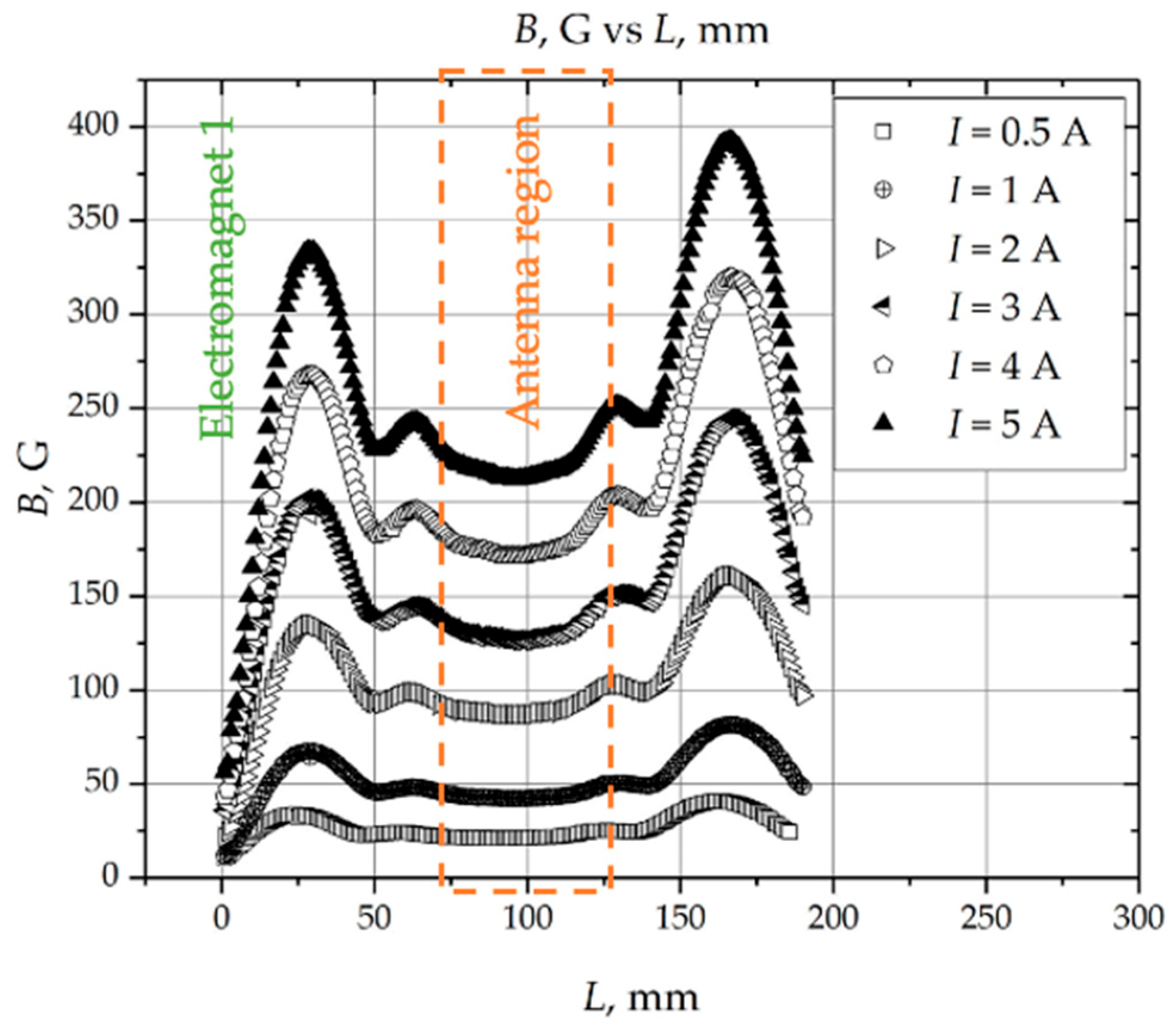
4.1. General Analysis

This subsection mainly discusses general conclusions that can be drawn from the 3D starting mode diagrams.
The starting modes are above the threshold surfaces (Figure 10). For the conditions considered, the electric breakdown field, E , is in the range of 440 to 2400 V/m. The minimum breakdown field is reached at d = 10 mm, a propellant flow rate of 20 sccm, and a magnetic field corresponding to 5 A (400 G in a peak). For the remaining conditions, the minimum field is about 750 V/m. It can be seen that for all conditions considered, the minimum breakdown field is in the region of the minimum propellant flow rate (20 sccm) and the maximum magnetic field (corresponding to 5 A).
Based on Figure 10, there is a tendency for the breakdown electric field to decrease as the magnetic field increases for a given propellant flow rate (corresponding to certain pressure conditions within the gas discharge chamber). For example, by applying an external longitudinal magnetic field, the threshold electric field can be reduced by up to 5 times (Figure 10f). Such a dependence can be explained, on the one hand, by the fact that the magnetic field causes cyclotron motion of the electrons, which results in a lengthening of the electron trajectories during the electron oscillations caused by the azimuthal RF electric field. This elongation allows the electrons to gain more energy in a half period of oscillation time. Since the energy for the electrons sufficient for gas breakdown is mainly related to electron–electron collisions in the case of the RF electric field, the additional gain of energy for the electrons in a half period of oscillation time is favorable and results in the reduction in the threshold electric field in the case of magnetized RF gas breakdown. On the other hand, the magnetic field causes transverse and longitudinal electron drifts, which are critical and will be discussed in the following subsection. Varying the inner diameter of the orifices allows significant control of the starting modes. For example, in cases b and c in Figure 10, the threshold electric field is almost the same (~800–1000 V/m) for all propellant flow rates and magnetic fields. Such a dependence can be related to the electron loss inside and the re-entry of exhausted electrons into the gas discharge chamber. From this phenomenon, it can be inferred that the stable processes of discharge breakdown can be achieved when the inner diameter of orifices is small. On the other hand, the larger inner diameter of orifices allows a significant reduction in the threshold electric field (by 2.5 times at 5 A in electromagnets and a propellant flow rate of 20 sccm).
It can be seen that the minimum pressure, p m i n , at which breakdown occurs is shifted to the lower values as the magnetic field strength increases.
Since the breakdown field at 0.5 A in electromagnets is independent of the magnetic field and is consistent with other experiments [32], it can be considered as the RF breakdown field for the case without magnetic field, while the addition of the external magnetic field to the bi-directional plasma thruster allows the reduction in the breakdown electric field by a maximum of ~5 times for the considered conditions.

4.2. Contradictions to Previous Studies on Magnetized RF Breakdown

The results for the starting modes of the bi-directional plasma thruster contradict the previous ones for the magnetized RF plasma breakdown.
Radmilovic-Radjenovic proposed the equation for determining the threshold electric field for initiating the RF discharge in the presence of the static magnetic field in the unidirectional RF plasma source, V E , B d [33]:
V E , B d = B k k p 1 + C ( B / p ) 2 l n A k Γ k + l n ( p d 1 + C ( B / p ) 2 ) k
where k is empirically determined to be equal to 1 and 2 for molecular and atomic gasses, correspondingly; A k , B k , and C are coefficients depending on conditions; Γ = ln 1 + 1 γ ; γ is the third Townsend’s coefficient; B is the magnetic field magnitude, G; and p is the pressure inside the gas discharge chamber, Torr.
Radmilović-Radjenović also proposed the minimum pressure (in Torr) at which the magnetized RF breakdown occurs as a function of the static magnetic field [33]:
p m i n = e 2 k Γ k 2 C d 2 B k 2 A k 2 A k d
where A k , B k , and C are the coefficients depending on the gas, Γ k = α d is the sparking criterion, and k is the index empirically determined to be one for the molecular gases and two for the atomic gases.
Based on Equation (5), the threshold electric field for initiating a gas discharge should increase as the static magnetic field strength increases. Also, based on Equation (6), the minimum pressure at which the magnetized RF breakdown occurs is directly proportional to the static magnetic field strength. In addition, based on the results of experiments performed in [35] with a unidirectional RF plasma source, there is a static magnetic field magnitude above which there is no possibility of initiating the magnetized RF discharge at very low pressures (when the mean free path of electron–neutral collisions is larger than the characteristic size of the system). In contrast to the results presented in [33,34], the breakdown electric field in the bi-directional plasma thruster study decreases with increasing magnetic field strength. The results obtained for the thruster can be explained theoretically by classical diffusion theory and nonlinear effects in RF plasmas. These theories are discussed in the following subsections. In addition, the following discussion sheds light on the inconsistency of the results that can be obtained using Equation (5), makes the connection between the obtained experimental data and [35], and explains the possible inaccuracies in Kumar’s experiment [36].

4.3. Classical Diffusion Theory

The results on the starting modes of the bi-directional plasma thruster are in good agreement with the classical diffusion theory.
The Maxwellian energy distributions are assumed for the electrons. Cylindrical coordinates are considered. The z coordinate is located along the axis of the gas discharge chamber. The r coordinate is located along the radius of the gas discharge chamber. The equation for the conservation of the number of electrons in the presence of the static magnetic field can be written as follows:
n e t = ν i n e + D T 1 r r r n e r + D L 2 n e z 2 e E c o s ( ω t ) m e ν e n n e φ ,
where n e is the electron number density, e is the negative elementary charge, m e is the electron mass, ν e n is the elastic electron neutral collision frequency, D T is the transverse diffusion coefficient, D L is the longitudinal diffusion coefficient, and E is the induced eddy electric field propagating along φ coordinate.
The first term on the right-hand side in Equation (7) is the generation of electrons and the second and third are the loss of electrons in the transverse and longitudinal directions relative to the gas discharge chamber axis. The fourth term on the right-hand side in Equation (7) is the mass vibrations of the electrons in a radiofrequency field along the φ coordinate.
In the case of isotropic electron diffusion, the transverse, D T , and longitudinal, D L , diffusion coefficients are equal and can be determined as follows:
D T = D L = k T e m e ν e n .
From Equation (8), it can be theoretically concluded that for the pure radiofrequency discharge, the transverse diffusion coefficient decreases within the pressure increase affecting ν e n .
When the magnetic field that is parallel to the axis of the gas discharge chamber affects the diffusion of electrons, e.g., ω c e 2 / ν e n 2 1 , where ω c e is the electron cyclotron resonance frequency, the electron transverse diffusion coefficient that is affected by the magnetic field, D T B , can be determined as follows [40]:
D T B = k T e ν e n m e ω c e .
From Equation (9), it can be theoretically concluded that the electron transverse diffusion coefficient affected by the magnetic field, D T B , decreases within the increase in the magnetic field affecting ω c e for a given pressure. Based on the assumption that in the steady state ( n e t = 0), the electron density, n e , must reach the maximum at the moment of breakdown (Equation (7)), the reduction in the transverse diffusion coefficient is favorable for the discharge breakdown for conditions when ω c e 2 / ν e n 2 1 , since the transverse electron losses decrease.
However, the decrease in D T B should be considered unfavorable for the unidirectional RF plasma sources. In [41], the transition of electron trajectories from a weak ( ω c e / ν e n < 1) to strong ( ω c e / ν e n >> 1) magnetic field is reported. The trajectories of the electrons collapse to points in the case of a strong magnetic field. In the presence of a strong magnetic field, the electrons move in closed orbits. At very low pressures ( λ > L s y s t e m ), magnetized electrons do not undergo ionizing collisions. This phenomenon is consistent with Equation (5).
However, for the bidirectional plasma thruster, increasing the magnetic field leads to the opposite result. For case f in Figure 10 (d = 10 mm), the pressure in the central region of the gas discharge chamber is in the range of 2.7 to 27 Pa (the threshold electric field is in the range of 440 to 2200 V/m). The corresponding elastic electron neutral collision frequency, ν e n , is in the range of 4.8 to 48 s−1. The electron cyclotron resonance frequency, ω c e , is in the range of 70 to 630 s−1, corresponding to the DC current supplied to the electromagnets in the range of 0.5 to 5 A. Based on these conditions, the ratio ω c e 2 / ν e n 2 1 , which indicates the dependence of the electron transverse diffusion coefficient, is in the range of 2 to 17 × 104 (see Table 1).
The ratio ω c e 2 / ν e n 2 1 indicates that, under certain conditions, the breakdown electric field is strongly dependent on the magnetic field for DC currents of 3, 4, and 5 A (corresponding to magnetic fields of 125, 175, and 225 G in the central region of the gas discharge chamber), while in the case of 0.5 A, the breakdown electric field is mostly independent of the external magnetic field ω c e 2 / ν e n 2 ~ 1 . Also, for 0.5 A, the other cases in Figure 10 are mostly independent of the applied magnetic field. The minima of the Paschen branch of the RF breakdown curves for each case in Figure 10 for 0.5 A supplied to the electromagnets are where the condition ω ν e n are in agreement with other experiments [32]. For example, for case a in Figure 10, the minimum of the Paschen branch for 0.5 A is 40 sccm, corresponding to ν e n = 1.5 × 10 7 s−1, which is approximately equal to ω = 1.4 × 10 7 s−1.
The difference between the unidirectional and bi-directional plasma thrusters in terms of the gas breakdown in the magnetized RF plasma can be explained as follows. While the transverse diffusion of electrons is limited, the longitudinal diffusion still takes place. The electrons leaving the gas discharge chamber in the unidirectional plasma thruster do not have the opportunity to re-enter the chamber and can be considered as losses. In contrast, the electrons leaving the chamber of the bi-directional plasma source can re-enter the chamber from the opposite side of the open-ended gas discharge chamber.
The current discussion ignores the phenomenon observed in the experiments of Weibold et al. The increase in the RF breakdown electric field in both the unidirectional and bidirectional RF plasma sources at a very low pressures, as in the experiments in [35], within the increase in the magnetic field can be described by the modification of Equation (7):
0 = ν i n e + D T B ( 1 B ) · 1 r r r n e r + D L B ( 1 B 2 ) · 2 n e z 2 b ( 1 B ) · e E c o s ( ω t ) m e ν e n n e φ ,
where D L T is the electron longitudinal diffusion coefficient in the presence of the external magnetic field and b ( 1 B ) is the coefficient quantitively showing the limitations on the mass vibrations of electrons in a radiofrequency field along the φ coordinate within the increase in the external magnetic field magnitude.
According to Equation (9), when B , ω c e and D T B 0 . Thus, the second term on the right side of Equation (10) tends to zero.
In the absence of the externally applied magnetic field, the electron longitudinal diffusion coefficient is a function of the thermal velocity, υ T , D L = υ T λ . In the presence of the static longitudinal magnetic field and under the condition ω c e 2 / ν e n 2 1 , D L B becomes a function of the drift velocity, υ T ~ 1 / B , and D L B ~ 1 / B . Thus, as B , D L B 0 and the third term on the right-hand side of Equation (12) tends to zero.
Thus, if ω c e 2 / ν e n 2 1 , B , and p , the breakdown electric field E . This dependence is assumed in Figure 10f and provides the connection to the results presented in [35]. The tendency of the breakdown electric field to decrease with increasing magnetic field strength and decreasing propellant flow rate cannot be continuous. The gas breakdown cannot occur at either a zero electric field or a zero propellant flow rate. In addition, there are magnetic field strengths at which discharge breakdown is not possible at very low pressures when the electron mean free path, λ , is greater than the characteristic dimensions of the system, L s y s t e m   ( λ > L s y s t e m ) [35]. Thus, it is necessary to add a coefficient to the fourth term in Equation (7)—which is b ( 1 B ) in Equation (10)—that reflects the increase in the magnetic field.
The addition of the coefficient b ( 1 B ) to the mass vibrations of electrons term allows three regions of the radiofrequency breakdown in the RF plasma source with the external longitudinal magnetic field to be covered by the electron conservation of mass equation. Without the magnetic field effects ( ω c e 2 ν e n 2 < 1 ) , the electron density, n e , gradually increases and the breakdown electric field decreases. When ω c e 2 ν e n 2 1 , there is a sharp increase in n e corresponding to the sharp decrease in the breakdown electric field, and when B and p , n e 0 . The drastic decrease in the electron density,  n e , results in E .

4.4. Pondermotive Effect

The results for the starting modes of the bi-directional plasma thruster are in good agreement with the pondermotive effect theory for RF plasmas.
In the electromagnetic field, fast particle oscillations, averaged over time, give rise to the net effect known as the ponderomotive force [42,43]. In the fluid approximation, the ponderomotive force, F M , is given by the Miller formula [42]:
F M = e 2 E 2 2 m ω 2 + ν e n 2 .
The ponderomotive force plays a role in the energy gain of electrons from an RF field at low pressures [40].
Equation (11) is for the unmagnetized RF plasma. To construct the equation for the ponderomotive force in the case of magnetized RF plasma, the equation for electron motion in the electromagnetic field is considered:
m v t + m ν v = e E + e v × B r f + e v × B d c ,
where B r f is the magnetic field from the radiofrequency field and B d c is the static magnetic field.
The radiofrequency electric and magnetic fields change according to the following laws:
E t = E sin ω t + φ ,
B r f t = B r f cos ω t + φ ,
Substitution of Equations (13) and (14) arranged in series into Equation (12) leads to
m v t + m ν v = e E 0 sin ω t + φ + e r · E 0 s i n ( ω t + φ ) + e v × B d c + e ω v × ( × F r f 0 ) c o s ( ω t + φ ) ,
The solution of Equation (15) with respect to the electric field can be represented as follows:
F M B = e 2 E 2 4 m ω 2 + ν e n 2 e v × B d c .
Based on Equation (16), it can be seen that the increase in the static magnetic field leads to the increase in the ponderomotive force. As a result, the electrons gain more energy for ionizing collisions in the magnetized plasma than in the unmagnetized plasma for the same period of time. The experimental results are in good agreement with Equation (16).
From Equation (16), it can be concluded that the change in the threshold electric field, E , is proportional to B 0.5 for a given pressure. This result is in good agreement with the experimental results when the ω 2 ν e n 2 1 (for example, at 20 sccm in Figure 10f).

4.5. Active Electron Source

There is one important note that is left over from the previous discussion. Kumar et al. [36] reported a similar dependence of the breakdown electric field on the magnetic field obtained for the unidirectional RF plasma source as in the study of the bi-directional plasma thruster. In the experiments of Kumar et al. [36], the source is placed inside the vacuum chamber. The antenna and its connections to an RF generator are not shielded and are surrounded by the conditions inside the vacuum chamber. Since the conditions for the gas breakdown around the antenna and/or its connections to an RF generator can be more favorable than those inside the gas discharge chamber, the discharge can be started outside of the gas discharge chamber. For example, the bi-directional plasma thruster has also been tested without the shielding of the connection lines and without using the N-type feedthrough. The discharge starts around the non-isolated antenna–RF generator connection lines and then moves inside the gas discharge chamber of the source because the electric field strength between the lines is 2 × 10⁴ V/m, which is 50 times higher than that inside the gas discharge chamber at the same current in the antenna (see Figure 11). This situation may occur in Kumar et al.’s experiment [36]. In this case, the electrons generated outside the gas discharge chamber can enter the chamber and reduce the RF breakdown.
In the case of magnetized RF plasma, the reduction in the threshold is due to the fact that the externally generated electrons enter the gas discharge chamber by being trapped by the magnetic field lines, while having enough energy for ionization in the conditions inside the gas discharge chamber. More specifically, the externally generated electrons can be trapped by the magnetic field lines and re-enter the gas discharge chamber only when the magnetic field lines are directed toward the inner cavity of the chamber. This configuration of the magnetic field lines cannot be applied in the case of the unidirectional electrodeless plasma thruster, because it is suggested that the magnetic field is directed to the outside of the gas discharge chamber, especially when the unidirectional thruster is considered to generate the impulse force, for example, for attitude corrections in remote sensing to ensure the long capture band or to track a moving object. In contrast, in the case of multidirectional PS, such as the bi-directional plasma thruster, the magnetic field at one end of the gas discharge chamber can be directed downstream of the inner cavity, while at the other end, the magnetic field lines are directed upstream and the electrons trapped by the magnetic field can re-enter the gas discharge chamber, resulting in reduced electron losses.
The fact that externally generated electrons facilitate breakdown and the ability to create regions of increased electric field strength allow the use of active electron sources in multidirectional plasma thrusters. At the end of the gas discharge chamber, where the thrust is not considered to be created, where the magnetic field lines are directed to the inner cavity, the active electron source can be used at the moment of discharge ignition to reduce the threshold electric field strength.

5. Conclusions

The starting modes of the bi-directional plasma thruster operated in krypton are studied and mode diagrams are constructed in the dimensions of the threshold electric field, the magnetic field strength determined by the DC current in the magnetic system, and the propellant flow rate in the range of 20 to 200 sccm. It is found that the breakdown electric field can be reduced by 5 times by applying the external longitudinal magnetic field. The minimum breakdown electric field that can be achieved in the investigated thruster is 440 V/m. The trends of the starting modes of the bi-directional plasma thruster differ significantly from the theoretical studies dedicated to the unidirectional magnetized RF plasmas. Nevertheless, it is shown that the results are in good agreement with the general theory of the processes in the magnetized RF plasmas for the bi-directional plasma source.
The difference between the unidirectional and bi-directional plasma sources in terms of gas breakdown in the magnetized RF plasma is that while transverse diffusion of electrons is limited, longitudinal diffusion still occurs. The electrons leaving the gas discharge chamber in a unidirectional plasma source do not have the opportunity to re-enter the chamber and can be considered as losses. In contrast, the electrons leaving the chamber of the bidirectional plasma source can re-enter the chamber from the opposite side of the open-ended gas discharge chamber.

Author Contributions

Conceptualization, A.I.S.; methodology, A.I.S.; software, A.I.S.; validation, A.I.S., V.D.T. and S.V.R.; formal analysis, A.I.S.; investigation, A.I.S.; resources, A.I.S.; data curation, A.I.S.; writing—original draft preparation, A.I.S.; writing—review and editing, A.I.S.; visualization, A.I.S.; supervision, A.I.S.; project administration, A.I.S. All authors have read and agreed to the published version of the manuscript.

Funding

This research received no external funding.

Data Availability Statement

The data that support the findings of this study are available from the corresponding author upon reasonable request.

Conflicts of Interest

The authors declare no conflict of interest.

References

  1. Feuerborn, S.A.; Perkins, J.; Neary, D.A. Finding a way: Boeing’s all electric propulsion satellite. In Proceedings of the 49th AIAA/ASME/SAE/ASEE Joint Propulsion Conference, San Jose, CA, USA, 13–17 July 2013. [Google Scholar] [CrossRef]
  2. Shumeiko, A.I.; Jarrar, F.S.; Swei, S.S. Advanced wave plasma thruster with multiple thrust vectoring capability. In Proceedings of the AIAA SCITECH 2022 Forum, San Diego, CA, USA, 3–7 January 2022. [Google Scholar] [CrossRef]
  3. Shumeiko, A.I.; Telekh, V.D.; Mayorova, V.I. Development of a novel wave plasma propulsion module with six-directional thrust vectoring capability. Acta Astronaut. 2022, 191, 431–437. [Google Scholar] [CrossRef]
  4. Takahashi, K. Thirty percent conversion efficiency from radiofrequency power to thrust energy in a magnetic nozzle plasma thruster. Sci. Rep. 2022, 12, 18618. [Google Scholar] [CrossRef] [PubMed]
  5. Takahashi, K.; Charles, C.; Boswell, R.W.; Ando, A. Demonstrating a new technology for space debris removal using a bi-directional plasma thruster. Sci. Rep. 2018, 8, 14417. [Google Scholar] [CrossRef] [PubMed]
  6. Romano, F.; Chan, Y.A.; Herdrich, G.; Traub, C.; Fasoulas, S.; Roberts, P.C.E.; Smith, K.; Edmondson, S.; Haigh, S.; Crisp, N.H.; et al. RF helicon-based inductive plasma thruster (IPT) design for an atmosphere-breathing electric propulsion system (ABEP). Acta Astronaut. 2020, 176, 476–483. [Google Scholar] [CrossRef]
  7. Shumeiko, A.I.; Telekh, V.D.; Mayorova, V.I. Development of a six-directional plasma propulsion module for small satellites. In Proceedings of the 71st International Astronautical Congress, Virtual, 12–14 October 2020. [Google Scholar]
  8. Sekine, H.; Koizumi, H.; Komurasaki, K. Electrostatic ion acceleration in an inductive radio-frequency plasma thruster. Phys. Plasmas 2020, 27, 103513. [Google Scholar] [CrossRef]
  9. Shumeiko, A.I.; Jarrar, F.S.; Swei, S.S. Development of novel electrodeless plasma thruster with multiple thrust vectoring capability. In Proceedings of the 72nd International Astronautical Congress, Dubai, United Arab Emirates, 25–29 October 2021. [Google Scholar]
  10. Shumeiko, A.I. Nature-Inspired Concepts for High-Power Electric Propulsion Systems. Fusion Sci. Technol. 2023. [Google Scholar] [CrossRef]
  11. Shinohara, S. Development of featured high-density helicon sources and their application to electrodeless plasma thruster. Plasma Phys. Control. Fusion 2018, 61, 014017. [Google Scholar] [CrossRef]
  12. Feldman, M.; Choueiri, E. Direct wave-drive thruster. J. Propuls. Power 2018, 34, 1124–1130. [Google Scholar] [CrossRef]
  13. Razin, Y. A direct fusion drive for rocket propulsion. Acta Astronaut. 2014, 105, 145–155. [Google Scholar] [CrossRef]
  14. Arefiev, A.; Breizman, B. Theoretical components of the VASIMR plasma propulsion concept. Phys. Plasmas 2004, 11, 2942–2949. [Google Scholar] [CrossRef]
  15. Takahashi, K. Comparison of vacuum-immersed helicon thrusters terminated by upstream magnetic and physical walls. J. Phys. D Appl. Phys. 2023, 56, 475207. [Google Scholar] [CrossRef]
  16. Shumeiko, A.I.; Telekh, V.D. Helicon engine in outboard air as a successful solution for maintaining small space vehicle in orbits up to 200 km. AIP Adv. 2023, 2171, 170019. [Google Scholar] [CrossRef]
  17. Ryzhkov, S.V. Magneto-Inertial Fusion and Powerful Plasma Installations (A Review). Appl. Sci. 2023, 13, 6658. [Google Scholar] [CrossRef]
  18. Kuzenov, V.V.; Ryzhkov, S.V.; Varaksin, A.Y. Simulation of Parameters of Plasma Dynamics of a Magneto Plasma Compressor. Appl. Sci. 2023, 13, 5538. [Google Scholar] [CrossRef]
  19. Kuzenov, V.V.; Ryzhkov, S.V.; Frolko, P.A. Numerical simulation of the coaxial magneto-plasma accelerator and non-axisymmetric radio frequency discharge. J. Phys. Conf. Ser. 2017, 830, 012049. [Google Scholar] [CrossRef]
  20. Kuzenov, V.V.; Seleznev, R.K.; Ryzhkov, S.V. Development of helicon plasma thruster model. In Proceedings of the 53rd AIAA/SAE/ASEE Joint Propulsion Conference, Atlanta, GA, USA, 10–12 July 2017. [Google Scholar] [CrossRef]
  21. Stark, W.; Gondol, N.; Tajmar, M. Concept and design of a hall-effect thruster with integrated thrust vector control. J. Electr. Propuls. 2022, 1, 21. [Google Scholar] [CrossRef]
  22. Buldrini, N.; Seifert, B.; Reissner, A. Ion Thruster for Thrust Vectored Propulsion of a Spacecraft. U.S. Patent Application No. 2021/0300599A1, 2 August 2018. [Google Scholar]
  23. Imai, R.; Takahashi, K. Demonstrating a magnetic steering of the thrust imparted by the magnetic nozzle radiofrequency plasma thruster. Appl. Phys. Lett. 2021, 118, 264102. [Google Scholar] [CrossRef]
  24. Takahashi, K.; Imai, R. Two-dimensional deflection of a plasma plume exhausted from a magnetically steered radiofrequency plasma thruster. Phys. Plasmas 2022, 29, 054501. [Google Scholar] [CrossRef]
  25. Shumeiko, A.I.; Telekh, V.D.; Ryzhkov, S.V. Probe diagnostics and optical emission spectroscopy of wave plasma source exhaust. Symmetry 2022, 14, 1983. [Google Scholar] [CrossRef]
  26. Thakur, S.C.; Brandt, C.; Cui, L.; Gosselin, J.J.; Tynan, G.R. Formation of the blue core in argon helicon plasma. IEEE Trans. Plasma Sci. 2015, 43, 2754–2759. [Google Scholar] [CrossRef]
  27. Shamrai, K.P. Stable modes and abrupt density jumps in a helicon plasma source. Plasma Sources Sci. Technol. 1998, 7, 499. [Google Scholar] [CrossRef]
  28. Chen, F.F. Helicon discharges and sources: A review. Plasma Sources Sci. Technol. 2015, 24, 014001. [Google Scholar] [CrossRef]
  29. Jiménez, P.; Merino, M.; Ahedo, E. Wave propagation and absorption in a helicon plasma thruster and its plume. Plasma Sources Sci. Technol. 2022, 31, 045009. [Google Scholar] [CrossRef]
  30. Kihara, T. The mathematical theory of electrical discharges in gases. Rev. Mod. Phys. 1952, 24, 45. [Google Scholar] [CrossRef]
  31. Lisovsky, V.A.; Yegorenkov, V.D. Low-pressure gas breakdown in combined fields. J. Phys. D Appl. Phys. 1994, 27, 2340. [Google Scholar] [CrossRef]
  32. Smith, H.B.; Charles, C.; Boswell, R.W. Breakdown behavior in radio-frequency argon discharges. Phys. Plasmas 2003, 10, 875–881. [Google Scholar] [CrossRef]
  33. Radmilović-Radjenović, M.; Radjenović, B. The effect of magnetic field on the electrical breakdown characteristics. J. Phys. D Appl. Phys. 2006, 39, 3002. [Google Scholar] [CrossRef]
  34. Radmilovic-Radjenovic, M.; Radjnovic, B. The influence of the magnetic field on the electrical breakdown phenomena. Plasma Sci. Technol. 2007, 9, 45. [Google Scholar] [CrossRef]
  35. Wiebold, M.; Ren, H.; Denning, C.M.; Scharer, J.E. Low-pressure helicon-plasma discharge initiation via magnetic field ramping. IEEE Trans. Plasma Sci. 2009, 37, 2110–2115. [Google Scholar] [CrossRef]
  36. Kumar, S.; Chandra, A.; John, P.I.; Sarkar, D.C. Study of rf breakdown characteristics in the presence of parallel electric and magnetic fields. J. Phys. D Appl. Phys. 1971, 4, 959. [Google Scholar] [CrossRef]
  37. Scheubert, P.; Fantz, U.; Awakowicz, P.; Paulin, H. Experimental and theoretical characterization of an inductively coupled plasma source. J. Appl. Phys. 2001, 90, 587–598. [Google Scholar] [CrossRef]
  38. Takahashi, K. Radiofrequency antenna for suppression of parasitic discharges in a helicon plasma thruster experiment. Rev. Sci. Instrum. 2012, 83, 083508. [Google Scholar] [CrossRef] [PubMed]
  39. Takahashi, K.; Takao, Y.; Ando, A. Low-magnetic-field enhancement of thrust imparted by a stepped-diameter and downstream-gas-injected rf plasma thruster. Plasma Sources Sci. Technol. 2019, 28, 085014. [Google Scholar] [CrossRef]
  40. Chen, F.F. Introduction to Plasma Physics; Springer Science & Business Media: Berlin/Heidelberg, Germany, 2012. [Google Scholar]
  41. Maiorov, S.A.; Kodanova, S.K.; Bastykova, N.K.; Golyatina, R.I.; Ramazanov, T.S.; Omiraliyeva, G.K. The effect of magnetic field on diffusion and drift of electrons in helium and xenon. Phys. Plasmas 2022, 29, 043502. [Google Scholar] [CrossRef]
  42. Godyak, V. Hot plasma effects in gas discharge plasma. Phys. Plasmas 2005, 12, 055501. [Google Scholar] [CrossRef]
  43. Smolyakov, A.I.; Godyak, V.; Tyshetskiy, Y. Effect of the electron thermal motion on the ponderomotive force in inductive plasma. Phys. Plasmas 2001, 8, 3857–3860. [Google Scholar] [CrossRef]
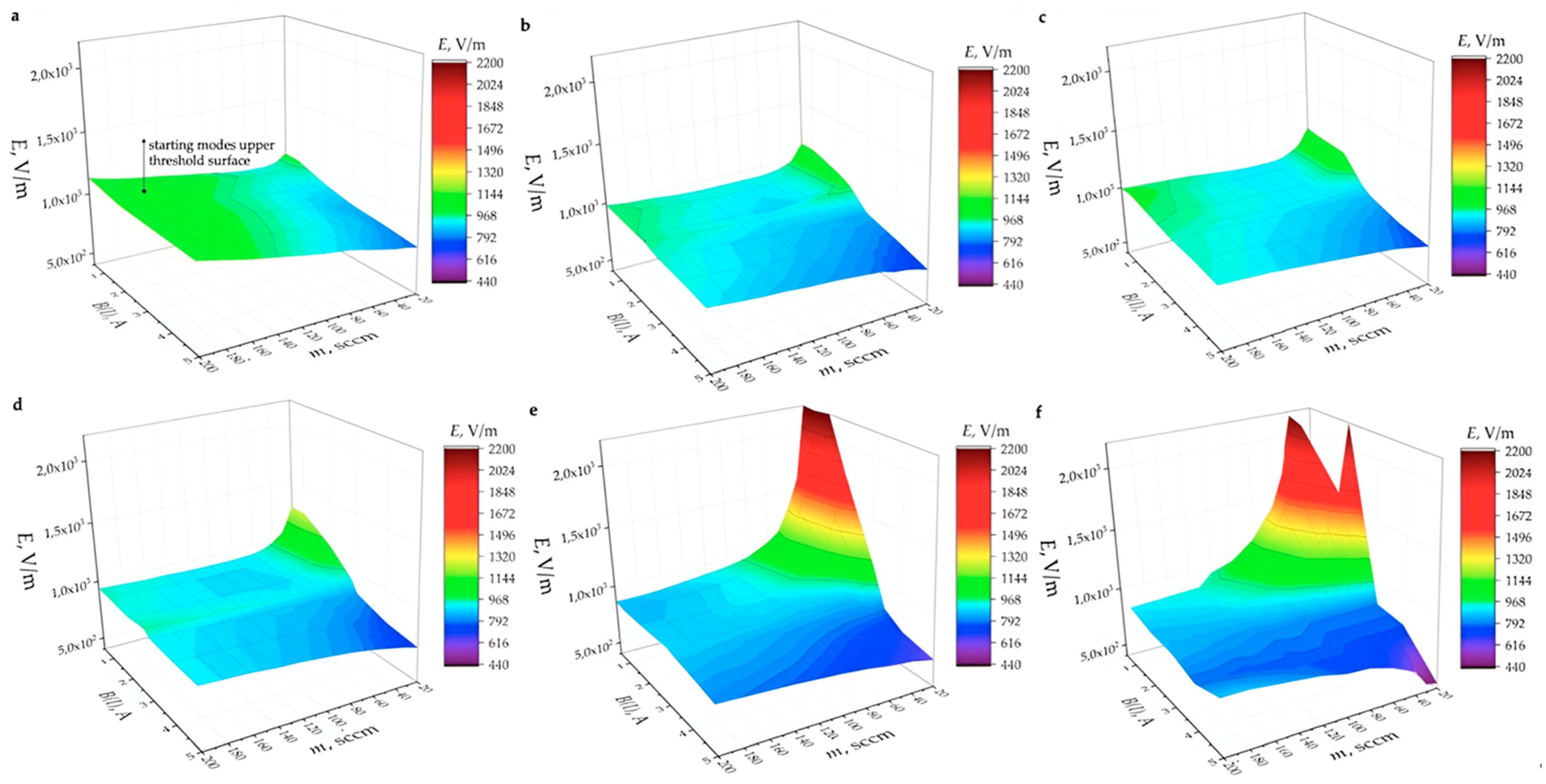
Figure 1. Bi-directional plasma source scheme: 1—gas discharge chamber; 2—antenna zone and shield surrounding antenna; 3—magnetic nozzles; 4—array of electromagnets; 5—casing for sub-systems; 6—orifices.
Symmetry 15 01705 g001
Figure 2. Measured magnetic field configuration within length of gas discharge chamber of bi-directional plasma source for different currents applied to magnetic system. The antenna region and the location of electromagnet 1 are added for reference.
Symmetry 15 01705 g002
Figure 3. 2D distribution of magnetic flux density at current of 5 A in electromagnets.
Symmetry 15 01705 g003
Figure 4. Scheme of experimental setup. Bold arrows indicate magnetic field direction of electromagnets inside the gas discharge chamber. Number and geometry of electromagnets are shown schematically. Numbers 1 and 13 represent electromagnet locations.
Symmetry 15 01705 g004
Figure 5. Test bench with bi-directional plasma thruster placed inside vacuum chamber.
Symmetry 15 01705 g005
Figure 6. Dynamic background pressure dependence on propellant flow rate in range of 20 sccm to 200 sccm.
Symmetry 15 01705 g006
Figure 7. Calculated pressure dependence on propellant flow rate for CH1 (145 mm) and CH2 (45 mm) gas inlets and antenna center (95 mm) locations inside the gas discharge chamber.
Symmetry 15 01705 g007
Figure 8. Calculated pressure dependence on propellant flow rate in the antenna center region for different orifices.
Symmetry 15 01705 g008
Figure 9. Discharge inside bi-directional plasma source.
Symmetry 15 01705 g009
Figure 10. Bi-directional plasma source starting modes in dimensions of eddy azimuthal electric field, E , magnetic field magnitude in current units supplied to electromagnets, B ( I ) , and propellant flow rate, m ˙ : (a)— d = 3 mm; (b)— d = 4 mm; (c)— d = 5 mm; (d)— d = 6 mm; (e)— d = 8 mm; (f)— d = 10 mm. Starting modes upper threshold surface.
Symmetry 15 01705 g010
Figure 11. Active electron source regions around non-isolated connection lines (blue lights around connection lines). Discharge starts around antenna–RF generator connection lines and then moves inside the gas discharge chamber of the thruster.
Symmetry 15 01705 g011
Table 1. The ω c e 2 / ν e n 2 ratio ranges for propellant flow rate of 20 to 200 sccm and d = 10 mm.
B ( I ) , A0.512345
ω c e 2 / ν e n 2 2 to 2 × 1028.4 to 8.4 × 1022.7 × 101 to 2.7 × 1035.3 × 101 to 5.3 × 1031 × 102 to 1 × 1041.7 × 102 to 1.7 × 10⁴
E , V/m900 to 2200850 to 2200800 to 790750 to 650650 to 490600 to 440
Disclaimer/Publisher’s Note: The statements, opinions and data contained in all publications are solely those of the individual author(s) and contributor(s) and not of MDPI and/or the editor(s). MDPI and/or the editor(s) disclaim responsibility for any injury to people or property resulting from any ideas, methods, instructions or products referred to in the content.

