Article

Study on the Nonlinear Stability and Parametric Analysis of a Tensile–Beam Cable Dome

1
College of Civil Engineering, Nanjing Forestry University, Nanjing 210037, China
2
Faculty of Architecture and Civil Engineering, Huaiyin Institute of Technology, Huaian 223001, China
3
National Prestress Engineering Research Center, Key Laboratory of C & PC Structures of Ministry of Education, Southeast University, Nanjing 210096, China
*
Author to whom correspondence should be addressed.
Symmetry 2023, 15(9), 1690; https://doi.org/10.3390/sym15091690
Submission received: 4 July 2023 / Revised: 23 August 2023 / Accepted: 29 August 2023 / Published: 2 September 2023
(This article belongs to the Special Issue Advances in Structural Mechanics and Symmetry/Asymmetry)

Abstract

:
To reveal the stable bearing capacity of a new semi-rigid dome structure, the tensile–beam cable dome (TBCD), a detailed numerical simulation and analysis of a 60 m model TBCD is conducted. Then, the effects of factors such as the prestress level, original imperfection size, original imperfection distribution, and addition of hoop tension rods on the stability of the TBCD model are investigated. The results show that the unstable loads of the TBCD are arranged from small to large in the following order: doubly nonlinearity with an original imperfection, geometry nonlinearity with an original imperfection, geometry nonlinearity without an original imperfection, and eigen buckling. In this case, the effects of geometry nonlinearity, material nonlinearity, and original imperfections must be comprehensively analyzed. The unstable mode of the TBCD depends on the loading form. Torsional buckling of the overall structure occurs under the symmetric load of ‘Full live + full dead’, while local out-of-plane buckling appears with the asymmetric load of ‘Half live + full dead’. With 2–3 times the loading integrations, the innermost tension beams change from stretch bending to pressurized bending, which causes the overall TBCD to become unstable. A small prestress level clearly decreases the stability of the TBCD, while a relatively large prestress level has little effect. When the original imperfection is greater than 1/400 of the span, the stability of the TBCD is problematic. Comprehensively considering the impact of multiple defects is needed when analyzing the buckling of the TBCD. Adding hoop tension beams between the top ends of rods can effectively improve the integrity and stability of the TBCD.

1. Introduction

Membrane films [1] are thin, flexible, lightweight panels with partial light transmission. However, the domestic climate and environmental pollution limit the use and popularity of membrane films and their application in cable-strut structures [2].
Rigid steel plates and glass sheets have been widely used in large-scale steel roof structures [3] with secondary cables. Because flexible cables have only axial stiffness and no bending stiffness, these cables must be set on the tops of the pressurized rods without setting on the cables. Otherwise, the structure will be very complex, and a relatively larger prestress level [4] should be built in advance to provide sufficient elastic support to bear the self-weight of the roof and to reduce the deflection of components.
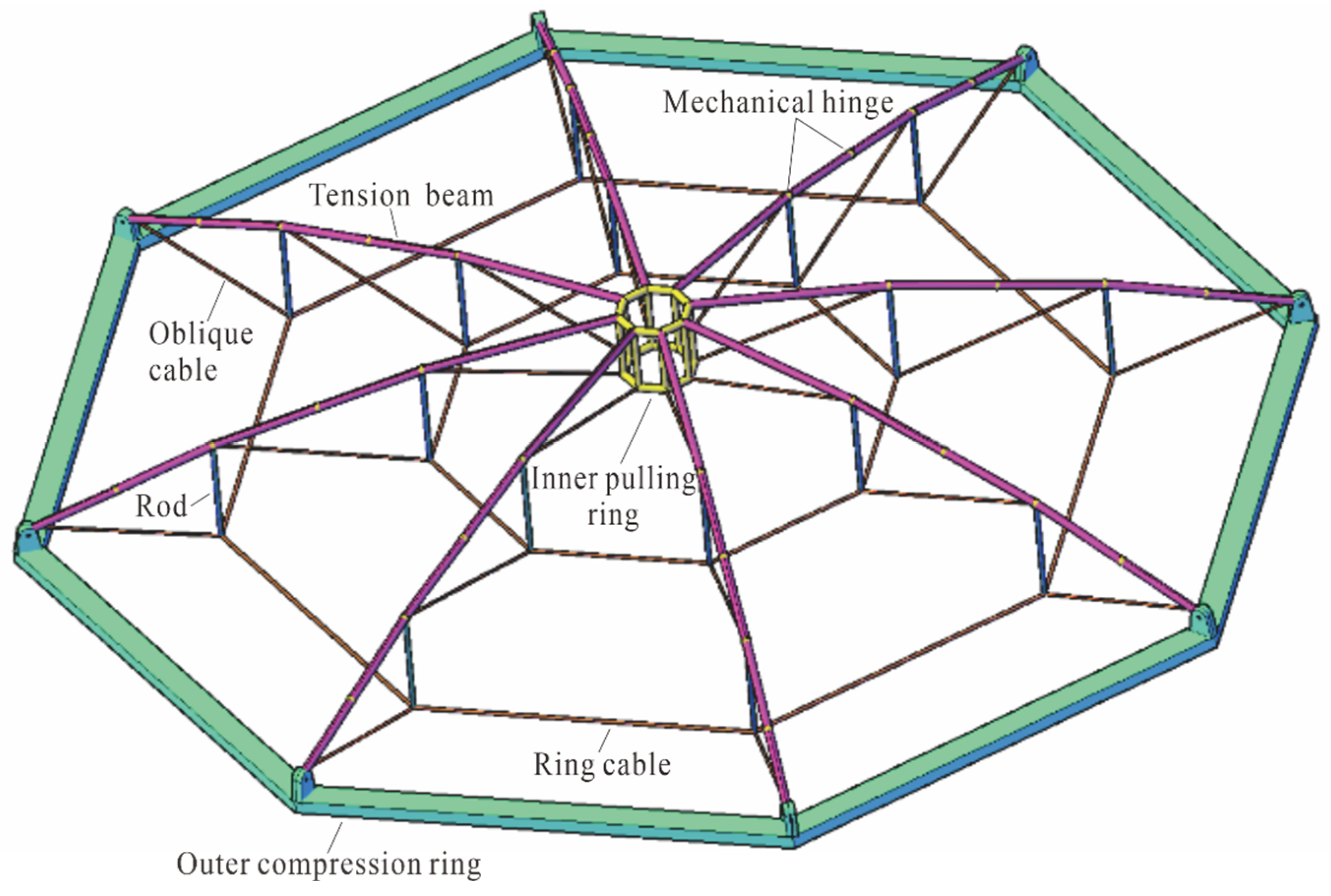
Recently, a new semi-rigid dome structure, the tensile–beam cable dome (TBCD) [5], was proposed by changing the upper cables of the cable dome to steel tubes, hinged at all ends and midpoints. Tension beams and adjacent components are connected by articulated nodes, which meet the mechanical demand for folding and unfolding and can realize the nonbracket expansion construction. Furthermore, due to the addition of upper tension beams, the TBCD has sufficient flexural rigidity to reduce excessive local deformation, and it can be welded or bolted to connect purlins and other roof auxiliary members. Therefore, the TBCD can be used to support heavy roofing systems. Zuo [6] conducted research on the mechanical properties and static simulations of Levy-type TBCDs and proposed several feasible setting modes for the connecting joints of ridge beams. Pan [7] designed an experimental model of a Geiger-type TBCD with a diameter of 6 m, verified the feasibility of the nonbracket construction method for the TBCD, and investigated the mechanical properties of TBCD under static loading conditions. Ding [8] established refined finite element models for TBCDs and then compared the static responses and vibration characteristics of TBCDs, suspended domes, and conventional cable domes. However, the above studies mainly focused on the force transmission and static response of the TBCD but not the stability performance of the TBCD.
Stability capacity refers to the ability of a structure to hold its form or undergo deformation in a loading state [9,10]. By utilizing the meshless generalized finite difference method (GFDM), Wang et al. [11] proposed a system for 3D composite elastic materials. Kabir and Aghdam [12] proposed a fine Bézier-based multistep method. Bert and Malik [13] introduce the latest research progress in analyzing laminated composite material structures using the differential quadrature method. In addition, Chen et al. [14] presented a correction project to reduce the difference between predicted and numerical results through finite element analysis (FEA). In fact, compared with a traditional cable dome, the upper rigid tension beam grid of a TBCD will impart significantly greater local stiffness. The pre-axial forces built in the tension beams will dramatically reform the stability to elastic deformation, thereby improving the stability of the overall structure.
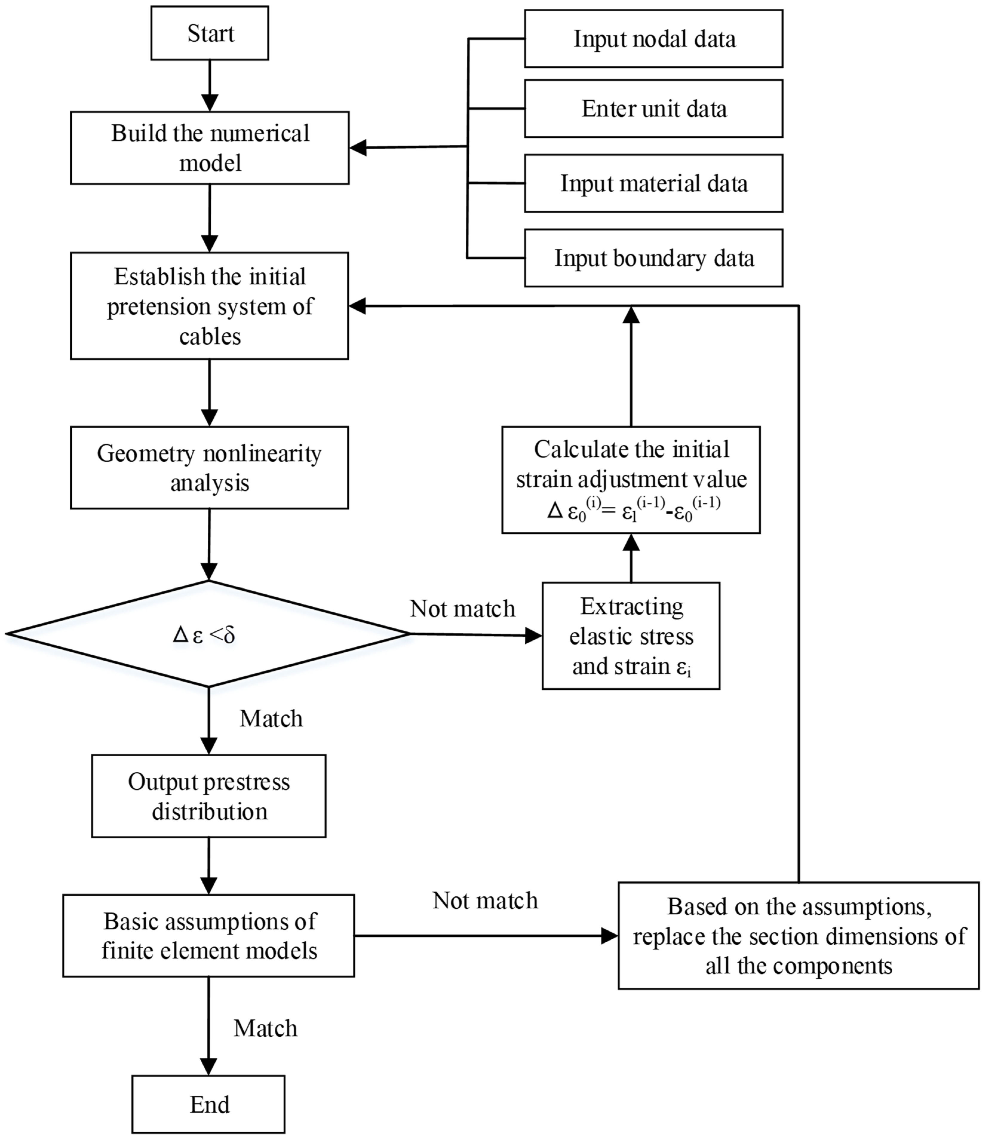
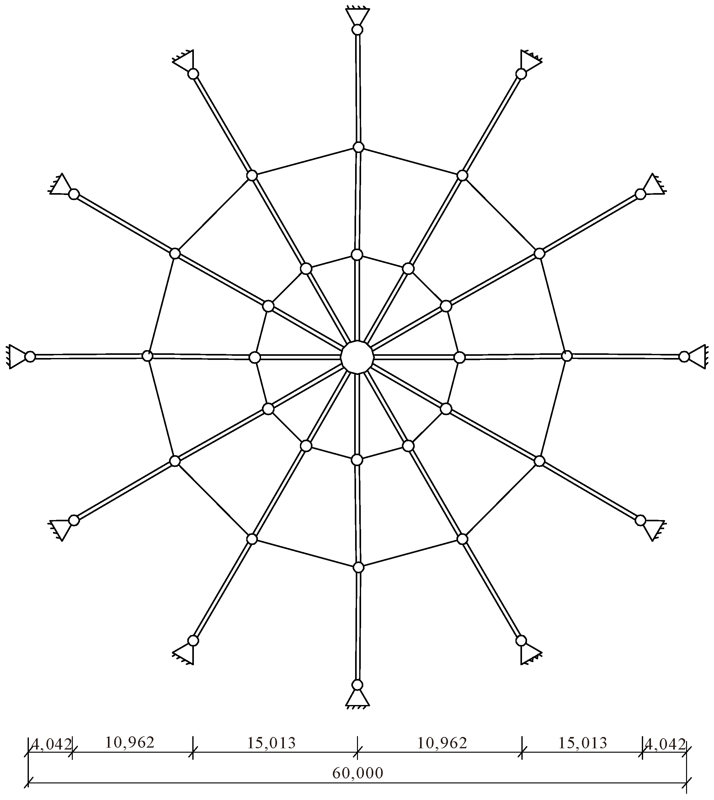
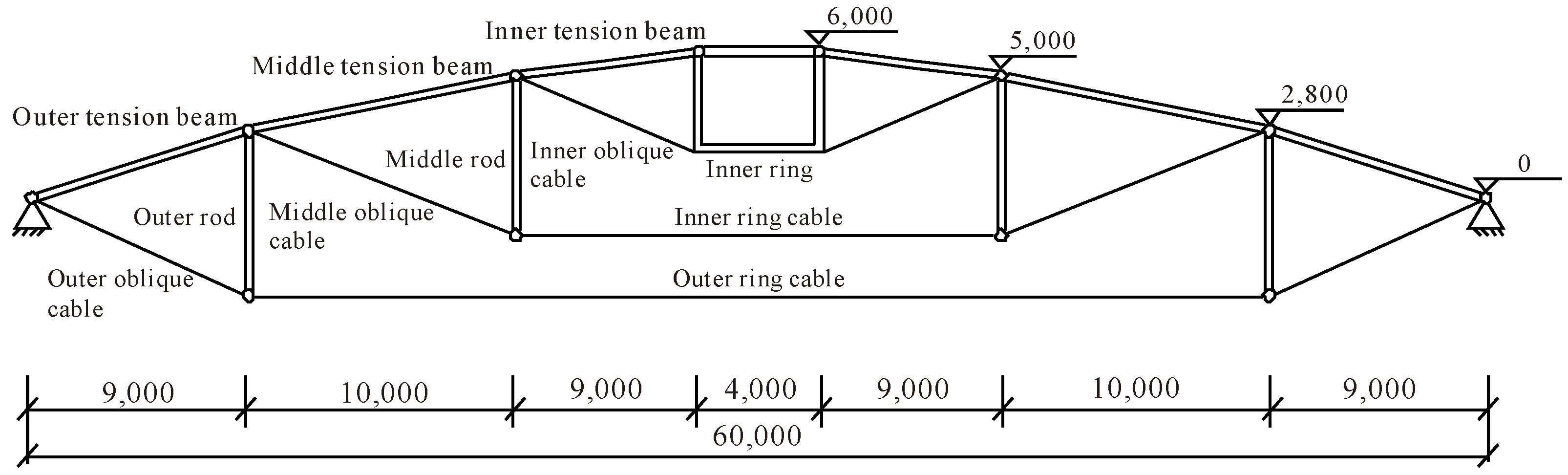
Based on the above considerations, a stability analysis of a TBCD is performed in this study. First, the basic assumptions and procedures of the finite element model are given, and then an eigen buckling analysis is conducted under two load cases. After that, a series of nonlinear stability analyses are performed considering the original imperfection and doubly nonlinearity. Then, the load magnification factor and nonlinear buckling mode of the structure under the specified load cases are obtained. Finally, the effects of several parameters, such as prestress level, original imperfection size, original imperfection distribution, and addition of circumferential members, on the stability performance of the TBCD are discussed.

2. TBCD Structure

By changing the upper cables of the cable dome to steel tubes, hinged at all ends and midpoints, a semi-rigid dome structure, the tensile–beam cable dome (TBCD). A TBCD is composed of tension beams, ring cables, an inner pulling ring, an outer pressurized ring, oblique cables, and several hinges arranged in the middle of tension beams (Figure 1) for convenient non-scaffolding erection.

3. Building of Numerical Model

3.1. Basic Assumptions

  • The tension beam and the inner pulling ring can bear axial forces and bending moments.
  • The cable is an ideal flexible body regardless of the bending stiffness [15].
  • The connections between the cable and rod, the cable and tension beam, and the rod and tension beam are ideal spherical hinges.

3.2. Iterative Force Analysis and Component Optimization Process

According to the above assumptions, an APDL program for iterative force analysis and model optimization is compiled. The calculation process is shown in Figure 2.

3.3. Philosophy of Numerical Models

When establishing the finite element model, sectional specifications of structural cables, tension beams, and rods must be improved to bear the dead load.
(1)
According to the “Standard for design of steel structures” (GB 50017-2017) [16], the vertical displacement of the top of the rod must not be greater than L/250 (L is the structural span) in the serviceability limit state.
(2)
Under the ultimate limit state, the maximum axial stretch force of the cable does not exceed 40% of the breaking force (i.e., 80% of the design strength), and the equivalent stress of the steel beams does not exceed 80% of the design value of its yield strength (i.e., 80% of the design strength).
(3)
According to the relevant provisions of the “Standard for design of steel structures” (GB 50017-2017) [16], the calculated length factor of the rods and welded steel pipes is 1.0, and the maximum compression forces of these components do not exceed their buckling loads, as listed in Equation (1).
N φ A f 1 . 0
where N, φ, A and f represent the axial force, stability factor, cross-sectional area, and yield strength of the member, respectively.
(4)
In reality, connection nodes with large dead weights are generally set between cables and rods or beams and cables to guarantee the integrity of the structure. According to Dong et al. [17], the dead weight of all the connecting nodes is equal to 30% of all the other components. This load is averagely distributed on both nodes of the rods.

3.4. Build the Numerical Model

The large-scale general analysis software ANSYS15.0 is utilized to build a numerical model. The stay cables adopt a three-dimensional two-node cable element with only tension, no compression, and no bending (LINK10). The rods are simulated by LINK8. The tension beams are in a state of stretch and bending, and the BEAM188 is thus used for the simulation of tension beams.
The finite element model is 60 m in span, 3 in the number of rings, 12 in the number of radial tension beams, and 6 m in sag height. The plan and section views of the model are shown in Figure 3 and Figure 4, respectively. The material properties and axial forces of the components are displayed in Table 1.

4. Stability Analysis

The following standard values for loads are considered:
(1)
Dead load: The self-weight of the upper roof (including the weight of inspection channels, lighting fixtures, etc.) and the uniformly distributed load on the roof are 0.8 kN/m2.
(2)
Live load: The uniformly distributed load on the roof is 0.5 kN/m2.
The buckling analysis process is listed as
  • Eigen buckling analysis. The linear buckling modes and eigenvalues are acquired.
  • Geometry nonlinearity analysis without an original imperfection. Based on the geometry nonlinearity theory, taking into account the effect of large deformation, the Newton-Raphson method is utilized to conduct the nonlinear buckling analysis.
  • Geometry nonlinearity analysis + original imperfection. The first-order linear buckling modes are regarded to be the forming pattern of original imperfections [18]. The largest value of the original imperfection is 1/300 of the span of the overall structure (i.e., 200 mm) [19].
  • Geometry nonlinearity analysis + material nonlinearity analysis + original imperfections. Simultaneously introducing the yield strength of components, the geometry nonlinearity, and the original imperfections to the analysis.
Two live load arrangements are considered, namely, full-span live load and half-span live load, and the corresponding buckling modes are obtained according to the live load arrangements. In this case, two types of loading cases are available: (1) Load Case I: Full-span dead load + full-span live load, and (2) Load Case II: full-span dead load + half-span live load (see Table 2).

5. Stability Analysis Results

5.1. Linear Buckling Analysis

Taking the TBCD model established above, a linear eigen buckling analysis is performed, and the first four buckling modes of the structure are acquired. The coefficient and buckling mode under Load Case I and II are shown in Table 3 and Table 4, respectively.
From Table 2 and Table 3, the following is shown:
The dispersion of the live load has a large effect on linear unstable modes and values. Under different load dispersions, the buckling modes are different.
Under the symmetric load of ‘Full live + full dead’, the first-order mode of TBCD is overall torsional deformation with an eigenvalue of 8.19, while the second-order and third-order modes of the TBCD are overall horizontal translation in two translational directions with eigenvalues of 9.13 and 10.2. The fourth-order mode of TBCD is local torsional deformation with an eigenvalue of 11.5.
Under the asymmetric load of ‘Half live + full dead’, first-order and second-order modes of the TBCD are local torsional deformations with values of 9.21 and 11.4, while the third-order and fourth-order modes of the TBCD are overall torsional deformations in two rotational directions with eigenvalues of 11.7 and 12.4.

5.2. Nonlinear Buckling Analysis

The nonlinear buckling analysis contains three cases: geometry nonlinear analysis, geometry nonlinear analysis + initial imperfection, and doubly nonlinear (geometry and material nonlinear) analysis + initial imperfection. Nonlinear analyses should follow these principles:
  • Considering the large deformation and stress stiffening effect, the Newton-Raphson method is utilized for cyclic iterative calculation.
  • The original imperfection is based on the consistent defect mode; the first-order mode of Load Case I is taken as the defect mode, and the largest size is 1/300 of the span.
  • When considering the nonlinear effect of the material, the constitutive relationship of the tension beams, rods, and inner ring employs a double-broken line style. The values are displayed in Table 5. Table 6 lists the load magnification factors and nonlinear buckling modes.
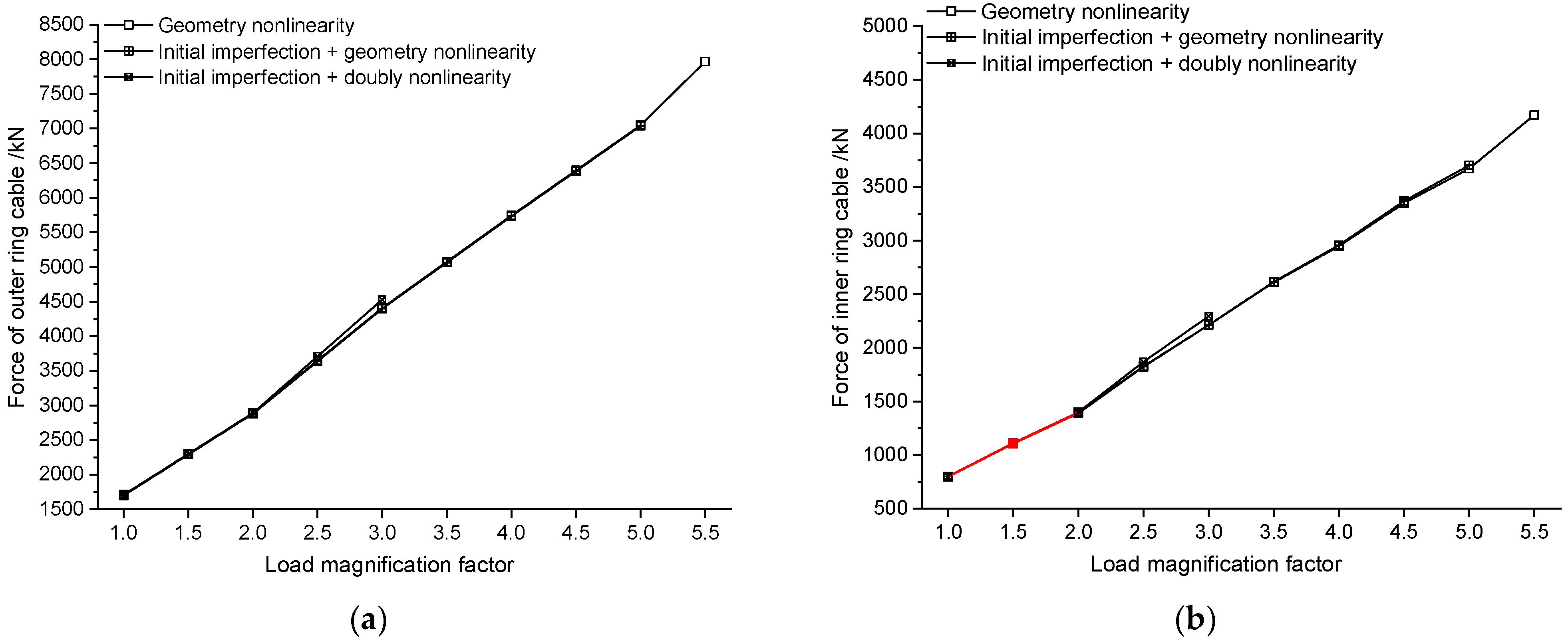
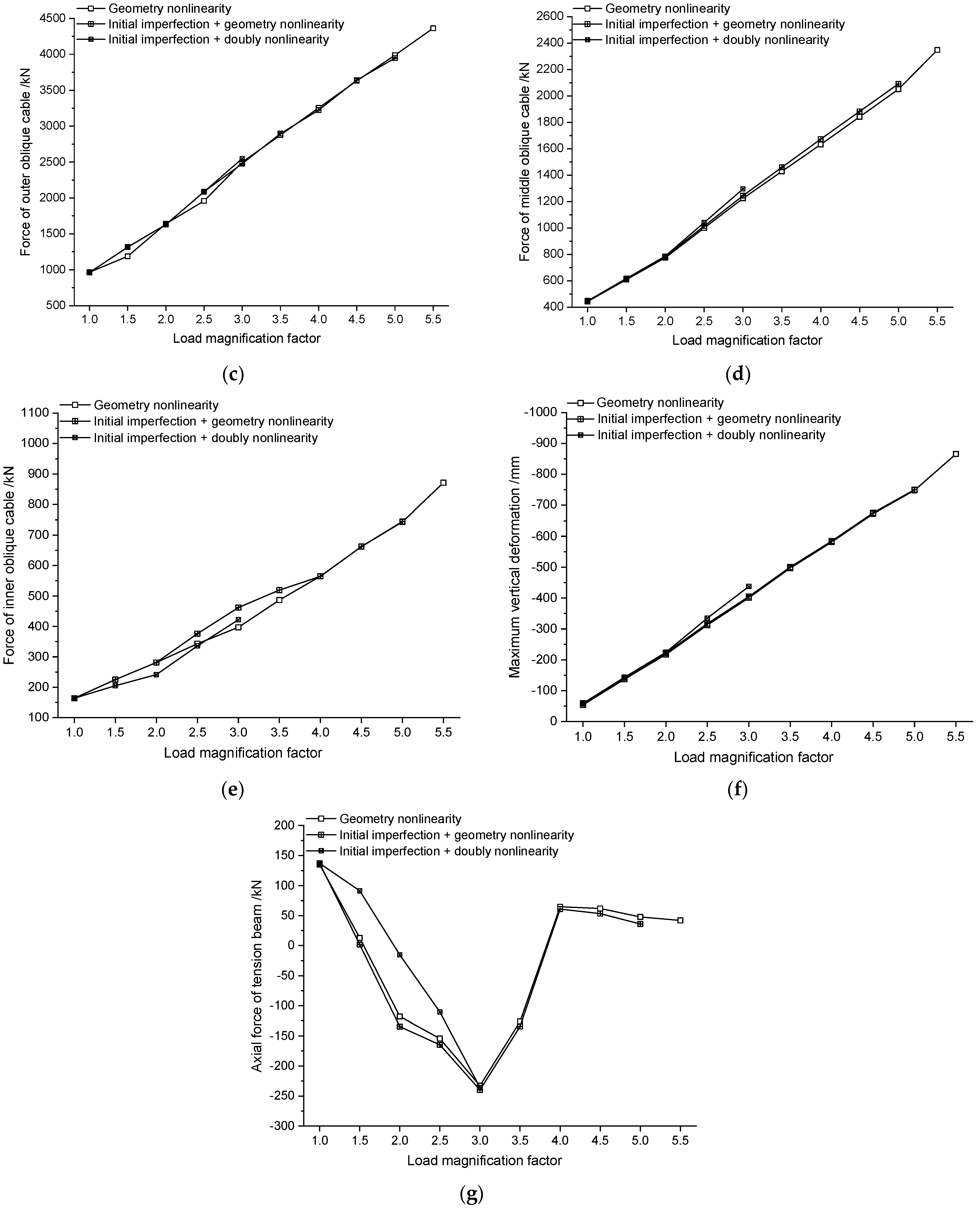
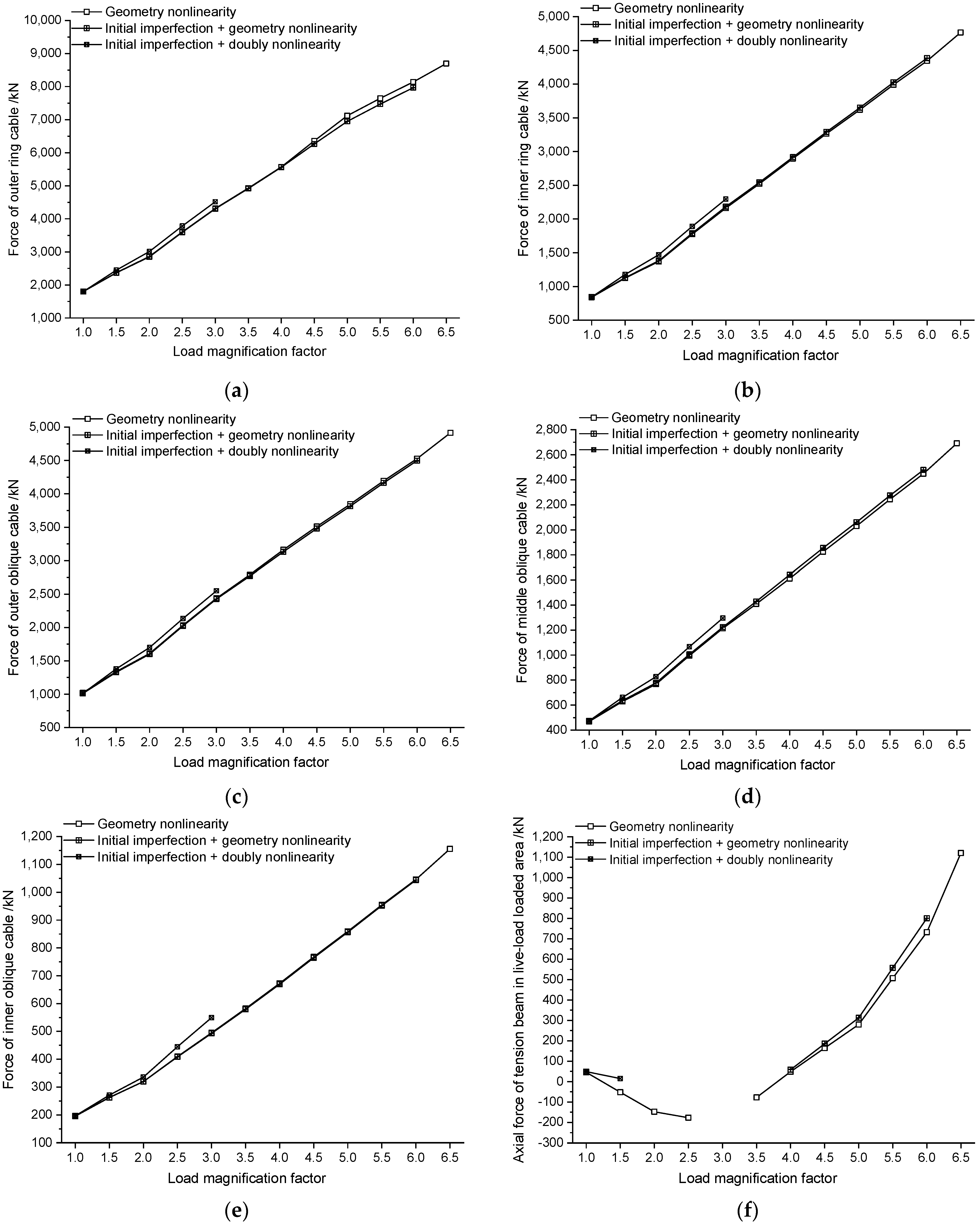
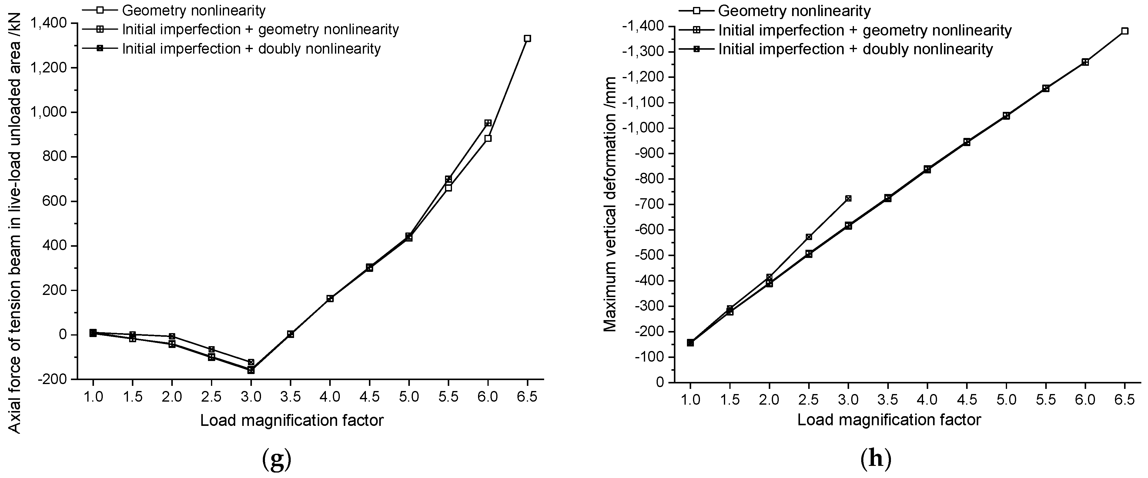
The corresponding oblique cable force-load curve, ring cable force-load curve, and maximum vertical displacement of the roof–load curve are shown in Figure 5 and Figure 6.
The conclusions are listed as follows.
(1)
The unstable loads of the TBCD are arranged from small to large in the following order: double nonlinear considering original imperfections, geometry nonlinearity with original imperfections, geometry nonlinearity without original imperfections, and eigen buckling. In this case, it is necessary to fully analyze the impacts of geometry nonlinearity, material nonlinearity, and original imperfections when performing buckling analysis of TBCD.
(2)
The live load arrangement has a great effect on nonlinear stability. Under the symmetric load of ‘Full live + full dead’, the stress pattern of the innermost tension beams transforms from stretch bending to pressurized bending, leading to the torsional buckling of TBCD. Under the case of asymmetric ‘Half live + full dead’, the bearing mode of components in the live-load region transforms from stretch bending to pressurized bending, leading to buckling of TBCD. The load magnification factors of half-span live arrangement are less than those of full-span distributed condition.
(3)
The original imperfection decreases the ultimate capacity. When the original imperfection increases from 0 to 1/300 of the structural span, the load magnification factors of the TBCD decline from 5.8 and 6.9 to 5.3 and 6.1, respectively, for these two load cases, which are reductions of 8.62% and 11.59%. This behavior indicates that the TBCD is sensitive to the original imperfection.
(4)
Due to the yielding of partial steel members, the stability-bearing ability of the TBCD undergoes a significant decrease after material nonlinearity is considered. The load magnification factors of the TBCD decrease from 5.3 and 6.1 to 3.0 and 3.3, respectively, for these two load cases, which are reductions of 43.39% and 45.90%. In this case, it is necessary to consider material nonlinearity when performing a stability analysis of the TBCD.
(5)
When applying 2~3 times the roof loads, the loading slopes of the oblique cable force, ring cable force, and maximum vertical displacement of the TBCD vary significantly, the bearing mode of the inner tension beams transforms from stretch bending to pressurized bending, and the equilibrium configuration of the entire structure changes considerably. In this process, the equilibrium configuration of TBCD undergoes great changes. The structure varies from the original unstable static equilibrium state to an unstable dynamic equilibrium state and finally reaches the stable static equilibrium state.
(6)
When adding doubly nonlinearities and original imperfections to the analysis process, the minimal load magnification factor of the TBCD appears in the symmetric load of ‘Full live + full dead’ with a specific value of 3.0. The stability capacity of the TBCD fulfills the demand of this regulation [19].

6. Parametric Analysis

To further investigate the stability performance of the TBCD, a series of parametric analyses are conducted considering the double nonlinearity and original imperfections. The parameters include the prestress level, the size of the original imperfection, the distribution of the original imperfection, and the addition of hoop tension beams.

6.1. Effect of Prestress Level

The prestress distribution of the finite element model is maintained, and the prestress level is varied as 0.8 times, 0.85 times, 0.9 times, 0.95 times, 1.0 times, 1.05 times, 1.1 times, 1.15 times, and 1.2 times the original prestress level in Table 1. The analyzed outcomes are demonstrated in Table 7.
When the prestress level is reduced to 0.8 times and 0.85 times the original prestress level, the load magnification factors of the two load cases are significantly reduced, while when the prestress level is increased to 1.15 times and 1.2 times, the load magnification factors of the two models undergo an insignificant increase. Furthermore, the variation in the prestress level does not change the buckling mode of the TBCD. In this case, the prestress level is one of the important factors determining the stable bearing capacity of the TBCD. If it is too small, it will obviously reduce the stability, but if it is too large, it will not contribute much to the improvement of the stability performance.

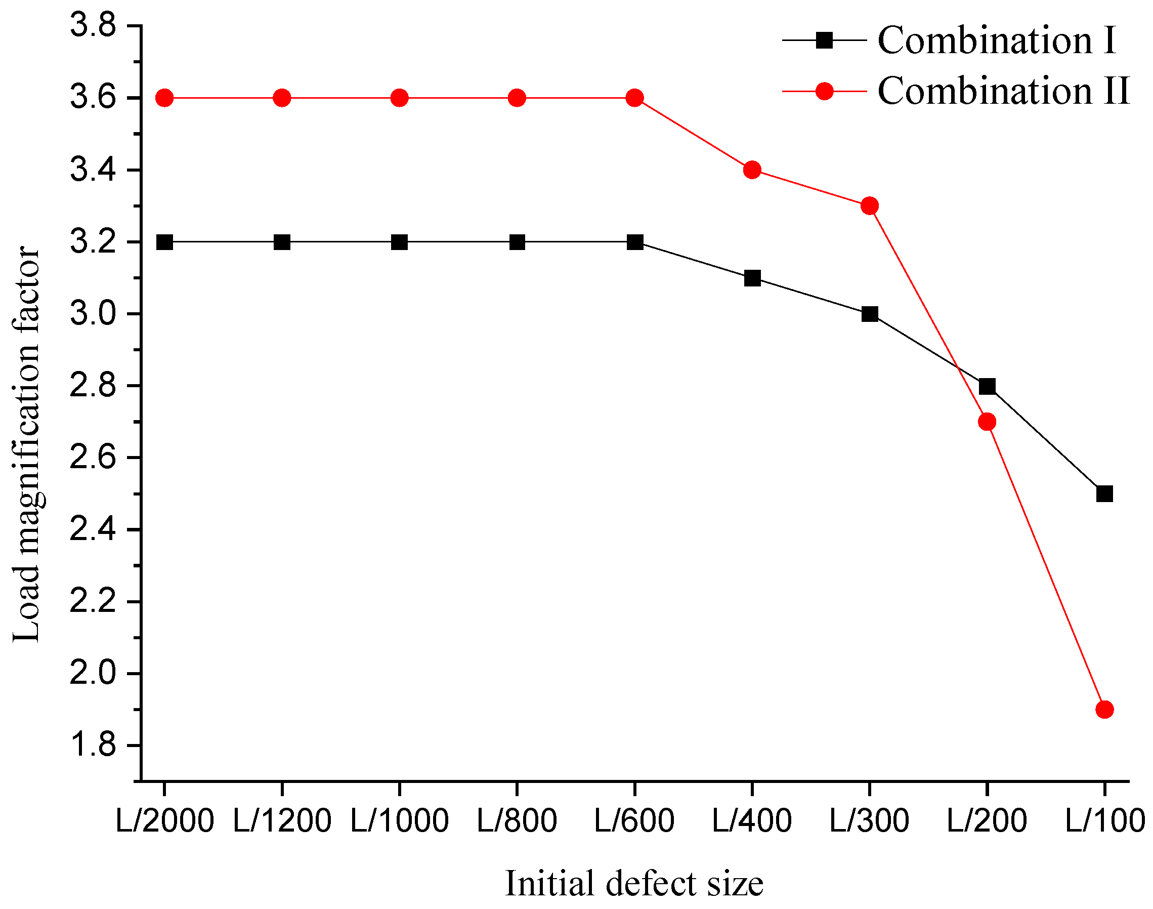
6.2. Effect of Original Imperfection Size

The largest value of the original imperfection is selected as 1/2000, 1/1200, 1/1000, 1/800, 1/600, 1/400, 1/300, 1/200, and 1/100, and the load magnification factor is shown in Figure 7.
The TBCD is not susceptible to the original imperfection with a small value. If the maximum original imperfection ranges from 1/2000 to 1/600 of the span, then the load magnification factors of the TBCD under the two cases are almost unchanged with the variation in the original imperfection size. However, when the original imperfection size changes in the range from 1/400 to 1/100 of the span, the stability decreases sharply with increasing defect size.

6.3. Effect of Original Imperfection Distribution

The first four buckling modes of the TBCD under Load Case I are used as the original imperfection distribution, 1/300 of the span is set as the maximum defect value, and a doubly nonlinear buckling analysis is performed.
Table 8 shows that the distribution of the original imperfection has a certain effect on the structural stability of the TBCD. Different types of defect distributions result in different buckling modes and load magnification factors. The load magnification factor obtained by the third defect distribution is the smallest. Therefore, using the first-order buckling mode of the eigen buckling analysis as the defect distribution does not necessarily provide the smallest load magnification factor, and it is necessary to comprehensively consider multiple defects.

6.4. Effect of Adding Annular Members

Hoop tension beams hinged at both ends are set on the top of the outer and middle rods. This member shares the same sectional specifications as the radial tension beams. A linear eigen buckling analysis is executed, and the first four buckling outcomes are obtained. The load magnification factors and buckling modes under the case of symmetric ‘Full live + full dead’ are shown in Table 9, and the buckling coefficient and buckling mode under the case of asymmetric ‘Half live + full dead’ are shown in Table 10. After that, the geometry nonlinear stability analysis without defects, the geometry nonlinear analysis with original imperfections (taking the first-order buckling mode as the defect distribution mode, the largest value set as 1/300 of the span), and the load magnification factors are shown in Table 11.
From Table 9 and Table 10, the following is shown:
(1)
Under the case of symmetric ‘Full live + full dead’, the first-order buckling mode of the TBCD maintains overall torsional deformation after adding hoop members, while the high-order buckling mode is the local deformation of the tension beams. The first-order eigenvalues of the TBCD with/without hoop tension beams are 8.19 and 13.2, respectively; thus, the stability of the TBCD improves after the hoop tension beams are added.
(2)
Under the case of asymmetric ‘Half live + full dead’, the first-order buckling mode of the TBCD transforms from original local torsional deformation to overall torsional deformation after adding hoop members, indicating that the addition of hoop tension beams limits the out-of-plane buckling of radial tension beams and improves the integrity of the TBCD. The first-order eigenvalues of the TBCD with and without hoop tension beams are 9.21 and 12.1, respectively. Thus, adding hoop members can also improve the stability of the TBCD.
Table 11 shows that hoop tension beams can be added between the top ends of the rods to improve the integrity and stability of the TBCD. Specifically, after adding hoop tension beams, the minimum load magnification factors rise from 3.0 and 3.3 s to 4.2 and 4.6 under these two load cases.

7. Conclusions

In this study, a linear eigen buckling analysis, a nonlinear buckling analysis, and a parametric analysis of stability are performed for TBCDs. The following conclusions are drawn:
(1)
The unstable loads of the TBCD are arranged from small to large in the following order: doubly nonlinearity with an original imperfection, geometry nonlinearity with an original imperfection, geometry nonlinearity without an original imperfection, and eigen buckling. In this case, the effects of geometry nonlinearity, material nonlinearity, and original imperfections must be comprehensively analyzed.
(2)
The buckling mode of the TBCD depends on the loading forms, and buckling behavior first occurs in the heavily loaded area. Under the symmetric load of ‘Full live + full dead’, the innermost tension beams of the TBCD transforms from stretch bending to pressurized bending, resulting in torsional buckling of the overall structure. However, under the case of asymmetric ‘Half live + full dead’, the tension beams in the live load region transform from stretch bending to pressurized bending, and partial buckling happens.
(3)
The prestress level is an important factor that affects the stability performance of the TBCD. A small prestress level obviously decreases the stability capacity of the TBCD, while if the prestress level is too large, then the prestress level does not contribute much to the stability performance.
(4)
The TBCD is not sensitive to an original imperfection with a small value, but when the original imperfection is greater than 1/400 of the span, the stability of the TBCD becomes problematic.
(5)
Using the first-order buckling mode of the eigen buckling analysis as the defect distribution does not necessarily obtain the minimum load magnification factor, and it is necessary to comprehensively consider multiple defects.
(6)
Adding hoop tension beams between the top ends of rods can effectively improve the integrity and stability of the TBCD.

Author Contributions

Conceptualization, J.G. and M.D.; Data curation, L.W. and B.L.; Formal analysis, M.D.; Funding acquisition, M.D.; Investigation, J.G. and L.W.; Methodology, J.G.; Resources, Y.R.; Software, M.D.; Supervision, L.W.; Validation, Y.R.; Visualization, B.L.; Writing—original draft, J.G. and M.D.; Writing—review and editing, J.G. All authors have read and agreed to the published version of the manuscript.

Funding

This research was funded by the National Natural Science Foundation of China, grant number 11673039; the Natural Science Foundation of Jiangsu Province, grant number BK20190753; the Natural Science Foundation of the Jiangsu Higher Education Institutions of China, grant number 18KJB560011; and the Priority Academic Program Development of Jiangsu Higher Education Institutions (PAPD). The APC was funded by the Natural Science Foundation of Jiangsu Province, grant number BK20190753.

Institutional Review Board Statement

Not applicable.

Informed Consent Statement

Not applicable.

Data Availability Statement

The data presented in this study are available on request from the corresponding author.

Conflicts of Interest

The authors declare no conflict of interest.

References

  1. Song, K.; Scarpa, F.; Schenk, M. Form-finding of tessellated tensegrity structures. Eng. Struct. 2022, 252, 113627. [Google Scholar] [CrossRef]
  2. Zhao, Y.; Guo, J.; Jiang, Z.; Chen, W.; Zhou, G. Control method for determining feasible pre-stresses of cable-struts structure. Thin-Walled Struct. 2022, 174, 109159. [Google Scholar] [CrossRef]
  3. Zong, Z.; Guo, Z. Nonlinear Numerical Analysis of Cable Dome Structure with Rigid Roof. Eng. Mech. 2009, 26, 134–139. [Google Scholar] [CrossRef]
  4. Ma, Q.; Ohsaki, M.; Chen, Z.; Yan, X. Multi-objective optimization for prestress design of cable-strut structures. Int. J. Solids Struct. 2019, 165, 137–147. [Google Scholar] [CrossRef]
  5. Luo, B.; Ding, M.; Pan, J.; Guo, Z.; Ruan, Y. Mechanical performance study of three joints tension-beam Geiger type cable dome structure. J. Build. Struct. 2016, 37, 61–67. [Google Scholar] [CrossRef]
  6. Zuo, Q. Research on the Performance Analysis and the Key Technology of Construction of Levy-Patterned Tensile-Beam Cable Dome. Master’s Thesis, Southeast University, Nanjing, China, 2017. [Google Scholar]
  7. Pan, J. Initial Form and Structural Behavior Analysis on Cable Dome of Rigid Roof Supported by Single-Layer Cable. Master’s Thesis, Southeast University, Nanjing, China, 2014. [Google Scholar]
  8. Ding, M.; Luo, B.; Pan, J.; Guo, Z. Experimental Study and Comparative Analysis of a Geiger-type Ridge-beam Cable Dome Structure. Int. J. Civ. Eng. 2018, 16, 1739–1755. [Google Scholar] [CrossRef]
  9. Dong, F.; Zhang, H. Probabilistic Safety Factor Calculation of the Lateral Overturning Stability of a Single-Column Pier Curved Bridge under Asymmetric Eccentric Load. Symmetry 2022, 14, 1534. [Google Scholar] [CrossRef]
  10. Dong, F.; Gao, J.; Hao, A.; Wei, Y.; Huang, X.; Shi, F.; Zheng, K. A New Approach to Symmetry Reliability: Combination of Forward and Inverse Reliability Principle and Its Application to Frame Structures and Bamboo Bridges. Symmetry 2022, 14, 318. [Google Scholar] [CrossRef]
  11. Wang, Y.; Gu, Y.; Liu, J. A domain-decomposition generalized finite difference method for stress analysis in three-dimensional composite materials. Appl. Math. Lett. 2020, 104, 106226. [Google Scholar] [CrossRef]
  12. Kabir, H.; Aghdam, M.M. A robust Bézier based solution for nonlinear vibration and post-buckling of random checkerboard graphene nano-platelets reinforced composite beams. Compos. Struct. 2019, 212, 184–198. [Google Scholar] [CrossRef]
  13. Bert, C.W.; Malik, M. Differential quadrature: A powerful new technique for analysis of composite structures. Compos. Struct. 1997, 39, 179–189. [Google Scholar] [CrossRef]
  14. Chen, Y.; Hu, Z.; Zhu, B.; Tong, G.; Guo, Y.; Wang, J. Stability design of axially loaded stringer-stiffened moderately-thick cylindrical shells in steel tubular transmission towers. Thin-Walled Struct. 2022, 172, 108874. [Google Scholar] [CrossRef]
  15. Duan, M.; Suo, X.; Dong, F.; Li, J.; Li, G. Research on the Control Method for the Reasonable State of Self-Anchored Symmetry Suspension Bridge Stiffening Girders. Symmetry 2022, 14, 935. [Google Scholar] [CrossRef]
  16. GB 50017-2017; Code for Design of Steel Structures. China Architecture & Building Press: Beijing, China, 2017. (In Chinese)
  17. Dong, S.; Wang, Z.; Yuan, X. A Simplified Calculation Method for Initial Prestress of Levy Cable Domes with the Consideration of Self-Weight. Eng. Mech. 2009, 26, 1–6. [Google Scholar]
  18. Jiang, Z.; Qiu, J.; Shi, K. Stability Analysis of Large Rise-span Ratio Special-shaped Single Layer Spherical Shells with Defects. Build. Sci. 2022, 38, 7. (In Chinese) [Google Scholar]
  19. JGJ 7-2010; Technical Specification for Spatial Grid Structure. China Architecture & Building Press: Beijing, China, 2010. (In Chinese)
Figure 1. Schematic diagram of a TBCD.
Symmetry 15 01690 g001
Figure 2. Flowchart of iterative force analysis and model optimization.
Symmetry 15 01690 g002
Figure 3. Plane figure of the TBCD.
Symmetry 15 01690 g003
Figure 4. Cross-sectional view of the TBCD.
Symmetry 15 01690 g004
Figure 5. Group diagram of the nonlinear analysis results of the TBCD for Load Case I. (a) Curves of load magnification factor vs. outer ring cable; (b) Curves of load magnification factor vs. inner ring cable; (c) Curves of load magnification factor vs. outer oblique cable; (d) Curves of load magnification factor vs. middle oblique cable; (e) Curves of load magnification factor vs. inner oblique cable; (f) Curves of load magnification factor vs. maximum vertical deformation; (g) Curves of load magnification factor vs. axial force of tension beam.
Symmetry 15 01690 g005aSymmetry 15 01690 g005b
Figure 6. Group diagram of the nonlinear analysis results of the TBCD (Load Case II). (a) Curves of load magnification factor vs. outer ring cable; (b) Curves of load magnification factor vs. inner ring cable; (c) Curves of load magnification factor vs. outer oblique cable; (d) Curves of load magnification factor vs. middle oblique cable; (e) Curves of load magnification factor vs. inner oblique cable; (f) Curves of load magnification factor vs. force of tension beam in live-load loaded region; (g) Curves of load magnification factor vs. axial of tension beam in live-load unloaded region; (h) Curves of load magnification factor vs. maximum vertical deformation.
Symmetry 15 01690 g006aSymmetry 15 01690 g006b
Figure 7. Load magnification factors of the TBCD under different original imperfection sizes.
Symmetry 15 01690 g007
Table 1. Component specifications and axial forces in the self-weight equilibrium state.
Component NameSection/mmAxial Force/NElastic Modulus before Yield/MPaYield Strength/MPaElastic Modulus after Yield/MPaUltimate Strength/MPa
Outer tension beamΦ390 × 20894.62.06 × 1053456180490
Middle tension beamΦ325 × 18501.52.06 × 1053456180490
Inner tension beamΦ273 × 16315.72.06 × 1053456180490
Outer oblique cableΦ55792.51.6 × 105835--
Middle oblique cableΦ40388.31.6 × 105835--
Inner oblique cableΦ25184.41.6 × 105835--
Outer ring cableΦ7014001.6 × 105835--
Inner ring cableΦ50699.71.6 × 105835--
Outer rodΦ100 × 10−315.32.06 × 1053456180490
Middle rodΦ80 × 10−141.82.06 × 1053456180490
Inner pulling ringΦ285 × 20-2.06 × 1053456180490
Table 2. Load case table.
NameLoad Case ILoad Case II
CaseFull live + full deadHalf live + full dead
Live load dispersionSymmetry 15 01690 i001Symmetry 15 01690 i002
Table 3. Eigenvalues and buckling modes (Load Case I).
OrderEigenvalueBuckling ModeOrderEigenvalueBuckling Mode
18.19Symmetry 15 01690 i003310.2Symmetry 15 01690 i004
29.13Symmetry 15 01690 i005411.5Symmetry 15 01690 i006
Table 4. Eigenvalues and buckling modes (Load Case II).
OrderEigenvalueBuckling ModeOrderEigenvalueBuckling Mode
19.21Symmetry 15 01690 i007311.7Symmetry 15 01690 i008
211.4Symmetry 15 01690 i009412.4Symmetry 15 01690 i010
Table 5. Material parameters of components.
Member NameElastic Modulus before Yield/MPaYield Strength/MPaElastic Modulus after Yield/MPaUltimate Strength/MPa
Tension beams, rods and inner ring2.06 × 1053456180490
Table 6. Load magnification factors and nonlinear buckling modes.
Load CaseLoad Magnification FactorBuckling Mode
Only Geometry NonlinearityGeometry Nonlinearity + Original ImperfectionDoubly Nonlinearity + Original Imperfection
Case I5.85.33.0Symmetry 15 01690 i011
Case II6.96.13.3Symmetry 15 01690 i012
Table 7. Load magnification factors and buckling mode of TBCD under different prestress levels.
Prestress LevelsLoad Case ILoad Case II
0.80Buckling modeSymmetry 15 01690 i013Symmetry 15 01690 i014
Load magnification factor2.42.8
0.85Buckling modeSymmetry 15 01690 i015Symmetry 15 01690 i016
Load magnification factor2.73.1
0.90Buckling modeSymmetry 15 01690 i017Symmetry 15 01690 i018
Load magnification factor3.03.3
0.95Buckling modeSymmetry 15 01690 i019Symmetry 15 01690 i020
Load magnification factor3.03.3
1.0Buckling modeSymmetry 15 01690 i021Symmetry 15 01690 i022
Load magnification factor3.03.3
1.05Buckling modeSymmetry 15 01690 i023Symmetry 15 01690 i024
Load magnification factor3.03.3
1.10Buckling modeSymmetry 15 01690 i025Symmetry 15 01690 i026
Load magnification factor3.23.5
1.15Buckling modeSymmetry 15 01690 i027Symmetry 15 01690 i028
Load magnification factor3.33.6
1.20Buckling modeSymmetry 15 01690 i029Symmetry 15 01690 i030
Load magnification factor3.33.6
Table 8. Load magnification factors and buckling modes of TBCD under different original imperfection distributions.
Original ImperfectionBuckling ModeLoad Magnification Factor
OrderDefect Distribution
1Symmetry 15 01690 i031Symmetry 15 01690 i0323.0
2Symmetry 15 01690 i033Symmetry 15 01690 i0342.4
3Symmetry 15 01690 i035Symmetry 15 01690 i0362.3
4Symmetry 15 01690 i037Symmetry 15 01690 i0383.4
Table 9. Eigenvalues and buckling modes under full-span live load.
OrderLoad Magnification FactorTBCDLoad Magnification FactorTBCD with Hoop Tension Beam
18.19Symmetry 15 01690 i03913.2Symmetry 15 01690 i040
29.13Symmetry 15 01690 i04120.3Symmetry 15 01690 i042
310.2Symmetry 15 01690 i04338.8Symmetry 15 01690 i044
411.5Symmetry 15 01690 i04540.6Symmetry 15 01690 i046
Table 10. Eigenvalues and buckling modes under a half-span live load.
OrderLoad Magnification FactorTBCDLoad Magnification FactorTBCD with Hoop Tension Beam
19.21Symmetry 15 01690 i04712.1Symmetry 15 01690 i048
211.4Symmetry 15 01690 i04918.9Symmetry 15 01690 i050
311.7Symmetry 15 01690 i05125.7Symmetry 15 01690 i052
412.4Symmetry 15 01690 i05327.7Symmetry 15 01690 i054
Table 11. Load magnification factors of the TBCD considering the effect of hoop tension beams.
Model TypeLoad CaseLoad Magnification Factor
Only Geometry NonlinearityGeometry Nonlinearity + Original ImperfectionDoubly Nonlinearity + Original Imperfection
TBCD without hoop tension beamsCase I5.85.33.0
Case II6.96.13.3
TBCD with hoop tension beamsCase I7.57.44.2
Case II9.59.34.6
Disclaimer/Publisher’s Note: The statements, opinions and data contained in all publications are solely those of the individual author(s) and contributor(s) and not of MDPI and/or the editor(s). MDPI and/or the editor(s) disclaim responsibility for any injury to people or property resulting from any ideas, methods, instructions or products referred to in the content.

