Article

Characterisation of Microstructure and Special Grain Boundaries in LPBF AlSi10Mg Alloy Subjected to the KoBo Extrusion Process

by
Przemysław Snopiński
1,* and
Krzysztof Matus
2
1
Department of Engineering Materials and Biomaterials, Silesian University of Technology, 18A Konarskiego Street, 44-100 Gliwice, Poland
2
Materials Research Laboratory, Silesian University of Technology, 18A Konarskiego Street, 44-100 Gliwice, Poland
*
Author to whom correspondence should be addressed.
Symmetry 2023, 15(9), 1634; https://doi.org/10.3390/sym15091634
Submission received: 30 June 2023 / Revised: 21 July 2023 / Accepted: 20 August 2023 / Published: 24 August 2023
(This article belongs to the Special Issue Electron Diffraction and Structural Imaging II)

Abstract

:
Grain boundary engineering (GBE) enhances the properties of metals by incorporating specific grain boundaries, such as twin boundaries (TB). However, applying conventional GBE to parts produced through additive manufacturing (AM) poses challenges, since it necessitates thermomechanical processing, which is not desirable for near-net-shape parts. This study explores an alternative GBE approach for post-processing bulk additively manufactured aluminium samples (KoBo extrusion), which allows thermo-mechanical treatment in a single operation. The present work was conducted to examine the microstructure evolution and grain boundary character in an additively manufactured AlSi10Mg alloy. Microstructural evolution and grain boundary character were investigated using Electron Back Scattered Diffraction (EBSD) and Transmission Electron Microscopy (TEM). The results show that along with grain refinement, the fraction of Coincidence Site Lattice boundaries was also increased in KoBo post-processed samples. The low-Σ twin boundaries were found to be the most common Coincidence Site Lattice boundaries. On the basis of EBSD analysis, it has been proven that the formation of CSL boundaries is directly related to a dynamic recrystallisation process. The findings show prospects for the possibility of engineering the special grain boundary networks in AM Al–Si alloys, via the KoBo extrusion method. Our results provide the groundwork for devising GBE strategies to produce novel high-performance aluminium alloys.

1. Introduction

Nature has always been full of symmetry and asymmetry. Many natural objects have symmetric shapes, which highlight the inherent order and balance in biological and geological systems. The symmetrical forms [1,2] such as the radial symmetry of a daisy or the bilateral symmetry of an orchid, exemplify the beauty of nature. The hexagonal symmetry of snowflakes [3,4], the bilateral symmetry of butterfly wings [5], and the symmetry of spiral galaxies [6] all demonstrate basic principles of symmetry in natural systems.
Symmetry also plays an important role in the field of materials science [7], where it provides a powerful framework for understanding the organisation, behaviour, and properties of materials at the atomic and molecular levels. In the context of metals science, symmetry manifests itself as a fundamental principle that underlies the arrangement of atoms and the formation of crystal structures [8]. The specific symmetry groups exhibited by the crystals provide insight into their physical properties, including mechanical behaviour, electrical conductivity, and optical response.
The characteristics of polycrystalline metals are closely related to the atomic subtleties associated with grain boundaries (GBs), which are fundamental structural elements and represent the interfaces where crystallographic orientations change abruptly. GBs could exhibit unique structural, chemical, and electronic properties that differ from those of bulk crystalline regions [9]. These characteristics have an important impact on various properties of the material, such as mechanical strength, corrosion resistance, and electrical conductivity, which is why grain boundaries are the subject of intense scientific investigation [10].
In pursuit of enhancing the properties of polycrystalline materials, researchers have taken two different approaches. One involves the engineering of material textures, while the other involves targeting special grain boundary distributions within the polycrystal. The motivation for the latter technique comes from the observation that different atomic structures at the grain boundary often give rise to different properties or responses [11]. Hence, the current essence of “grain boundary engineering” is to produce alloys with a high proportion of Σ3 twin boundaries (TB) and twin-related higher-order Σ3n (n = 2, 3; Σ ≤ 29) [12,13,14], referred to as low-sigma Coincidence Site Lattice (CSL) boundaries. As twin structures [15], including TBs, twins, and stacking faults (SFs), not only provide improved strength but also provide good ductility, harnessing the potential of CSL grain boundaries through precise manipulation and control therefore holds great promise for tailoring the properties of many polycrystalline materials [16].
Currently, the grain boundary engineering (GBE) of face-centred cubic (FCC) metallic materials, such as copper, nickel, lead alloys, and austenitic stainless steels, with low stacking fault energies (SFEs, primarily relies on thermo-mechanical processes (TMP). These processes involve cold deformation followed by heat treatment, taking advantage of the low SFE to promote the nucleation of annealing twins (ATs) in significant quantities. TMP can be categorised into two main approaches: strain-annealing and strain-recrystallisation. Both methods aim to increase the population of low-Σ (Coincidence Site Lattice) special grain boundaries (SBs) in metallic materials, which in turn modify random high-angle grain boundaries (RHAGBs) and hinder the connectivity of RHAGB networks [17]. However, materials with high SFEs face challenges in the development of twin structures or SBs. Consequently, the grain boundary engineering in aluminium and its alloys remains a complex undertaking [18].
To encourage the formation of growth twins in metals with high stacking fault energies (SFEs), a commonly employed strategy is to incorporate alloying elements. This incorporation results in the reduction of their SFEs, which facilitates the twinning process [19]. In recent years, researchers have also employed other techniques to successfully fabricate nanotwinned (NT) aluminium alloys. For example, surface engineering [20], cryogenic temperature deformation [21], and the incorporation of reinforcements such as carbon nanotubes (CNTs) [22,23] have been explored. Furthermore, bulk NT metals have also been successfully manufactured using high-rate, high-strain plastic deformation methods [24,25].
The KoBo extrusion process is a plastic deformation method that offers high-strain deformation at low temperatures [26], along with other plastic deformation techniques such as equal-channel angular pressing (ECAP) [27,28,29], high-pressure torsion (HPT) [30], and accumulative roll bonding (ARB) [31]. One distinguishing characteristic of KoBo extrusion is its ability to frequently change the deformation route, resulting in a substantial concentration of point defects at the atomic level, including vacancies and self-interstitial atoms (SIA), which alter the thermodynamic state of the material [32]. This characteristic is particularly intriguing for the fabrication of nanotwinned materials (NT), as the accumulation of SIAs has been associated with the occurrence of nanotwins [33,34]. Nevertheless, it remains unknown whether the KoBo extrusion process can induce the formation of high-density twins in laser powder bed fusion (LPBF) aluminium alloys, as this aspect has yet to be investigated. Furthermore, it is possible to unlock novel properties related to corrosion resistance, embrittlement, and fracture resistance by engineering the grain boundary network in Al-Si alloys of LPBF. This is because the crystallography of a grain boundary influences its diffusivity, mobility, and segregation behaviour. However, detailed knowledge of the crystallographic characteristics of Coincidence Site Lattice (CSL) grain boundaries in AM microstructures is currently lacking. In addition, the scope of materials engineering is expanding beyond traditional polycrystalline structures, with increasing interest in the synthesis and characterisation of interface-dominated structural alloys, such as nanostructured alloys.
The aim of this study is to explore an alternative grain boundary engineering (GBE) approach, specifically the KoBo extrusion post-processing method, for additively manufactured aluminium samples. The study investigates the evolution of the microstructure and grain boundary character of the AlSi10Mg alloy to assess the potential for engineering special grain boundary networks in additive manufacturing (AM) Al–Si alloys, ultimately paving the way for the design of AM-compatible GBE strategies to produce novel high-performance materials.

2. Materials and Methodology

The specimens were fabricated using the SLM TruPrint 1000 system from Trumpf (Ditzingen, Germany) using spherical powder of an AlSi10Mg alloy, Figure 1. The chemical composition of the powder used in this study, supplied by Sigma-Aldrich (Steinheim, Germany), is given in Table 1. The following SLM process parameters were used to fabricate dense samples: a laser power of 175 W, a layer thickness of 0.02 mm, a scanning speed of 1.4 m/s, and a zig-zag scanning strategy with an angle of 67 degrees rotation on each layer. Using these parameters, cylindrical specimens with a diameter of 60 mm and a height of 50 mm were successfully produced.
The KoBo extrusion process, the principle of which is described in the referenced study [35], was carried out without sample preheating, and the extrusion process was carried out using the following parameters:
  • punch speed of 0.2 mm/s;
  • die rotation angle of ±8°;
  • frequency of 5 Hz;
  • extrusion ratio λ of 225. The extrusion ratio λ signifies that the diameter of the rods after the KoBo extrusion process was equal to = 4 mm;
  • maximal measured temperature close to the extrusion die (~280 °C);
  • sample cooling—room-temperature water.
To conduct the microstructural investigation, a sample was carefully extracted from the middle part of the extruded rod. This specific location was chosen because it represents a region where the process parameters had stabilised.
A combination of light microscopy (LM), scanning electron microscopy (SEM), and transmission electron microscopy (TEM) was employed to study the microstructure in detail.
For LM investigations, the specimens were prepared using standard metallographic procedures. This included grinding (with 500 and 1200 grit SiC papers) and polishing (with 6, 3 and 1 µm diamond pastes) the samples to achieve a suitable mirror-like surface finish. The metallographic samples were etched with Keller’s reagent (2.5 mL HNO3, 1.5 mL HCl, 1 mL HF, and 95 mL H2O) for 60 s.
A scanning electron microscope was used to study the microstructure at higher magnification. The sample preparation for SEM followed the same procedure as for LM, with additional fine polishing with 0.04 µm colloidal silica for 1 h. This additional polishing step was performed to reduce the roughness of the surface and thus improve the quality of the EBSD signal.
Electron Backscatter Diffraction (EBSD) analysis was conducted using a scanning electron microscope (Zeiss Supra 35, Carl Zeiss NTS GmbH, Oberkochen, Germany) equipped with an EDAX NT EBSD detector (38 mm diameter) controlled by TSL OIM software. The TSL OIM EBSD software generated a comprehensive data set and visualisations, offering detailed information on the crystallographic orientation and microstructure of the analysed material.
The surfaces perpendicular to the scanning (LPBF sample) and transverse direction (KoBo sample) were selected for the EBSD characterisation. The following EBSD process parameters were used:
  • accelerating voltage: 20 kV;
  • sample tilt: 72°;
  • step size: 0.15 µm.
The EBSD orientation maps were then post-processed using ATEX software (Université de Lorraine: Metz, France) [36], which provided comprehensive information on grain boundary characteristics.
The grain-orientation-spread (GOS) maps were calculated based on the spread of crystallographic orientations within individual grains. The spread was measured in terms of misorientation angles between neighbouring measurement points within each grain. For a grain numbered i, its grain orientation spread, GOS(i), can be expressed as follows:
G O S i = 1 n 1 j = 1 i = n i ω g j g i
For the detection of recrystallised grains, a (GOS(i) < 2.5°) value was selected.
TEM analysis was performed to obtain detailed insights into the microstructure at the nanoscale. We used a Titan 80-300 FEI S/TEM microscope, which was operated at 300 kV. Electron diffraction images were further analysed using digital micrograph and CrysTBox (Crystallographic Toolbox) software. To fabricate the TEM sample, typical lamellae were cut from the extruded specimen using focused ion beam (FIB) milling. The lamellae were extracted parallel to the extrusion direction.
The TEM lamella was additionally analysed in SEM microscope using Transmission Kikuchi Diffraction (TKD) to obtain crystallographic information that allowed characterisation of grain boundaries with improved resolution. The sample was mounted in a custom-made holder that held it at a net angle of 10° with reference to the horizontal. The working distance was set at 7.5 mm. The energy of the electron beam was kept constant at 20 kV throughout the analysis. The TKD map was acquired in ∼2 h with a step size of 20 nm and a TKD pattern resolution of 301 × 129 pixels. A total area of 12 μm × 5.2 μm was recorded. The TKD orientation map was then post-processed using ATEX software, which provided comprehensive information on grain boundary features. The CSL grain boundaries were evaluated according to the Brandon criterion of Δθ ≤ 15°∑−1/2 standard. To determine the sizes of grains, automated mean linear intercept measurement was employed.

3. Results

Figure 2 shows the microstructures of the AlSi10Mg alloy observed using a light microscope. In Figure 2a, one can see distinct and discontinuous laser scan traces. These scan tracks overlap with each other at an angle of approximately 67 degrees, which corresponds to the Zig-Zag scanning strategy used during the additive manufacturing process. This tracks arrangement is a characteristic feature of the LPBF microstructures.
Figure 2b shows the microstructure of the same AlSi10Mg alloy after undergoing the KoBo extrusion process. Here, a notable transformation is observed, as the unique laser scan tracks, which were prominent in the LPBF state, have disappeared.
A scanning electron micrograph (SEM) shows the microstructure of an AlSi10Mg in LPBF condition, in Figure 3a. As can be seen, the microstructure is characterised by a continuous cellular network of Si phases surrounding the primary Al phase. On closer examination, the microstructure exhibits heterogeneity, characterised by three distinct zones. The first corresponds to the heat-affected zone (HAZ), where the thermal impacts (increase in diffusion rate) during the LPBF process have resulted in partial rupture of the Si phase. The second zone corresponds to the coarse area of the melt pool (MP coarse), where the cellular Si network exhibits the largest size (average measured cell size of ~1.4 μm). The MP coarse area is the region that underwent an extended cooling period, which facilitates the growth of larger cells or dendrites of the Si phase (coarser structure forms where the melt pool experiences the lowest temperature gradient and the highest solidification rate) [37]. The third identified region corresponds to the MP fine area, where the cellular structures exhibit the smallest size (measured average cell size of ~0.4 μm) compared to those of the other regions. This suggests the fastest cooling rate or shortest solidification time during the LPBF process [38].
Figure 3b shows a detailed view of the microstructure of the KoBo sample. This SEM image reveals significant changes in the microstructure compared to the LPBF condition. It shows fine Si particles, indicating that the cellular network of the Si phase observed in the LPBF condition has been broken and transformed into discrete particles. In addition, agglomerates and clusters of silicon (Si) particles can be seen in certain areas of the SEM image (see yellow-dotted outlines) as evidenced by EDS analysis in Figure 4. The presence of these agglomerates suggests that a phenomenon known as Ostwald ripening [39] may have occurred during post-processing by KoBo extrusion.
The size of the individual Si particles observed in the SEM image ranges between 70 and 400 nanometres, indicating a significant reduction in size and implying a high degree of refinement accomplished during the KoBo extrusion process. The uniform distribution of Si particles in the alloy matrix indicates good mixing and dispersion during KoBo extrusion, resulting in a homogeneous microstructure. This uniform distribution can be beneficial for improving the mechanical properties and overall performance of the alloy. Remarkably, the statistical analysis performed using ImageJ software (NIG, United States) reveals that the volume fraction of the second-phase particles is approximately 20.1 ± 1%, which interestingly aligns with the volume fraction of the cellular eutectic network observed in the LPBF condition (approx. 20%).
The EBSD inverse pole figure (IPF-Z) map displays different grains with varying orientations, represented by distinct colour maps, as indicated by the unit triangle in Figure 5a. The black lines signify high-angle grain boundaries (HAGBs) with misorientations exceeding 15 degrees, while the red lines represent low-angle grain boundaries (LAGBs) with misorientations ranging from 2 to 15 degrees. The LPBF sample comprises fine equiaxed grains exhibiting relatively random orientations, with an average grain size of 6.3 μm (GTA = 5°), Figure 6a. The EBSD analysis reveals the presence of 22.8% LAGBs and 77.2% HAGBs, Table 2. The occurrence of LAGBs can be attributed to the elevated dislocation density resulting from the rapid solidification rates associated with the selective laser melting process.
Figure 5b shows the IPF-Z map of the KoBo processed sample. The image reveals a significant occurrence of the grain refinement process following KoBo extrusion, attributed to the dynamic recrystallisation processes. The grains are significantly smaller, with an average size of approximately 1.1 µm, Figure 6b. The reduction in grain size is evident across the entire map, indicating a consistent refinement of the microstructure throughout the sample.
Furthermore, it is evident that a majority of the grains exhibit orientations aligned with the ⟨111⟩ A1 or ⟨001⟩ A1 axes, which is a characteristic feature observed in extruded alloys [40]. Most of the high-angle grain boundaries observed in the IPF map are associated with the boundaries between grains oriented along the ⟨111⟩ A1 or ⟨001⟩ A1 axes, exhibiting misorientations of approximately ~55 degrees. On the other hand, grain boundaries with low-angle misorientations are primarily linked to grains oriented along the same axis. Based on the statistical data presented in Table 2, it is observed that Low-Angle Grain Boundaries (LAGBs) account for 9.2% of the GBs, while High-Angle Grain Boundaries (HAGBs) make up the remaining 90.8% of GBs.
The GOS maps of the LPBF and KoBo samples, represented using a colour gradient, are illustrated in Figure 7a,b correspondingly. In these maps, the grains appearing in dark grey denote the smallest GOS values, indicating that they are dislocation-free and are classified as recrystallised grains. The EBSD measurements reveal that the recrystallised fractions account for 92.6% and 93.5% in the LPBF and KoBo samples, respectively.
The grain-orientation-spread (GOS) maps, showcasing the CSL boundaries highlighted with rainbow colour coding, offer valuable insights into the distribution of CSL boundaries within the sample’s microstructures. Remarkably, in the LPBF state, the occurrence of low-Σ CSL boundaries is minimal, as depicted in Figure 8a. Furthermore, the Σ CSL boundaries are predominantly distributed in proximity to grains exhibiting relatively low GOS values.
After KoBo extrusion (as depicted in Figure 8b), the results indicate a notable increase in the fraction of low-Σ CSL boundaries. Specifically, the proportion of Σ3 boundaries has risen from approximately 0.6% to around 5%, while the fraction of Σ11 boundaries has increased from 1.3% to 6.3%. Furthermore, the fraction of Σ25b (nucleus of primary recrystallisation) [41] has significantly increased from 0.76% to about 7.77%. It is worth mentioning that the distribution of Σ CSL boundaries in the KoBo extruded state is similar to that observed in the LPBF state, where these boundaries are predominantly situated close to grains with low grain-orientation-spread values.
In Figure 9, the transmission Kikuchi diffraction (TKD) map provides a detailed visualisation of the grain orientation spread and the fraction of Coincidence Site Lattice (CSL) grain boundaries. This experimental result is crucial for a comprehensive characterisation of the microstructure in the KoBo sample. It is important to note that the fraction of Σ17b boundaries may be overestimated due to their detection mainly in areas with small pixel clusters (artefacts). Nevertheless, the results confirm the presence of Σ CSL boundaries in the analysed sample. Statistical analysis highlights that the highest fractions of CSL boundaries are observed for Σ3, Σ7, Σ11, and Σ13b, indicating their prevalence within the microstructure, Figure 10. Moreover, the presence of higher-order Σ9 twin boundaries indicate the occurrence of GBE mechanisms [42].
Figure 11a shows a bright-field (BF) transmission electron micrograph of the AlSi10Mg alloy in the LPBF condition, revealing distinct microstructural features. The image shows columnar cells, elongated grain structures formed during additive manufacturing, indicating the directional solidification pattern during 3D printing. A notable aspect of the bright-field image TEM is the brightness differences in the microstructure. The columnar cell boundaries appear much brighter due to compositional differences, as they are rich in the Si phase.
In contrast, the dark-field TEM image emphasises the presence of dislocations in the microstructure, a common feature of additively produced Al–Si alloys, Figure 11b. The rapid solidification and thermal gradients in 3D printing can lead to a higher dislocation density compared to conventional processes.
Figure 12 shows the BF TEM micrograph of the AlSi10Mg alloy sample after the KoBo extrusion process. In this image, multiple grain boundaries are clearly visible, demarcating individual grains within the microstructure. Additionally, one particular grain stands out, exhibiting a size of approximately 300–400 nm. Importantly, the grain size measurement observed in the bright-field TEM image is comparable to the grain size results obtained through electron backscatter diffraction (EBSD) analysis, Figure 4.
The high-resolution transmission electron microscopy (HRTEM) image, Figure 12b, provides a closer look at the grain boundary highlighted in the bright-field TEM image (see black-dotted square). The boundary appears to be mostly straight but with the incorporation of some facets, as indicated by the black arrows. This HRTEM image reveals the atomic structure of the asymmetric twin boundary with a Σ3 (221)1/(001)2 Φ  =  54.56° orientation relationship. Note that there are also several SFs that dissociated from the GB into grain at the areas near the facet junctions, which might serve to accommodate the misorientation deviation of this boundary from that of the ideal (002)/(111) ATGB (i.e., 54.56° versus 54.74°) [43].
The presence of a low-Σ value Coincidence Site Lattice (CSL) boundary indicates a low grain boundary energy, representing high fracture and corrosion resistance [44]. It should be pointed out that the presence of a CSL grain boundary observed through HRTEM aligns with the Electron Backscatter Diffraction (EBSD) data.

4. Discussion

4.1. CSL Boundary Formation

In this study, we investigated the formation of CSL (Coincidence Site Lattice) boundaries in a sample subjected to the KoBo extrusion process. The results revealed a significant increase in the fraction of low-Σ CSL boundaries, particularly Σ3, Σ7 and Σ11 boundaries, after the KoBo extrusion compared to the LPBF state. Additionally, the fraction of Σ25b (nucleus of primary recrystallisation) exhibited a remarkable increase. These observations prompt an exploration of the possible mechanisms underlying the formation of CSL boundaries in the KoBo-extruded sample.
One potential explanation lies in the deformation and recrystallisation processes during KoBo extrusion, where the plastic deformation leads to the generation of dislocations and the rearrangement of crystal grains. The subsequent recrystallisation may favour the nucleation of grains with low orientation spread values, which could coincide with the observed proximity of Σ CSL boundaries to these grains. In this regard, the formation of CSL boundaries can be attributed to the atomic interactions that occur as a result of a dynamic recrystallisation-driven grain boundary migration process [45]. Alternatively, it is also plausible that the rise in the fraction of low-Σ Coincidence Site Lattice boundaries is a consequence of interactions between the pre-existing CSL boundaries during recrystallisation [46]. These interactions may have facilitated the formation of new CSL boundaries, resulting in a higher prevalence of low-Σ CSL boundaries.
Furthermore, in the context of severe plastic deformation, a phenomenon known as grain boundary (GB) relaxation may occur when the grain size decreases below a critical threshold. The mechanism underlying this GB relaxation in nanostructured materials is believed to be triggered by the emission of partial dislocations and stacking faults from the grain boundaries [47]. It has also been shown that Si has the ability to lower the stacking fault energy [48], which might reduce the critical shear stress required to nucleate partial dislocations. Moreover, the solute atoms increase the localised stress needed for dislocation motion, thus reducing annihilation and rearrangement of dislocation.
Recent experimental evidence also points to the significance of strain-induced boundary migration (SIBM) in enhancing the frequency and distribution of CSL boundaries [49,50,51]. While the migration of grain boundaries during primary recrystallisation involves the formation and growth of nuclei with different orientations, SIBM leads to the creation of stress-free regions with the same orientation as the parent grain [52]. These stress-free orientation regions can be analysed using the density of geometrically necessary dislocations (GNDs).
Upon analysis, it is observed that in the KoBo processed sample, CSL boundaries are predominantly distributed in proximity to regions with a higher density of GNDs (depicted as red “hot spots” in Figure 13). Consequently, this specific mechanism can be considered negligible, as twinning occurs most frequently at the points of highest GND accumulation.

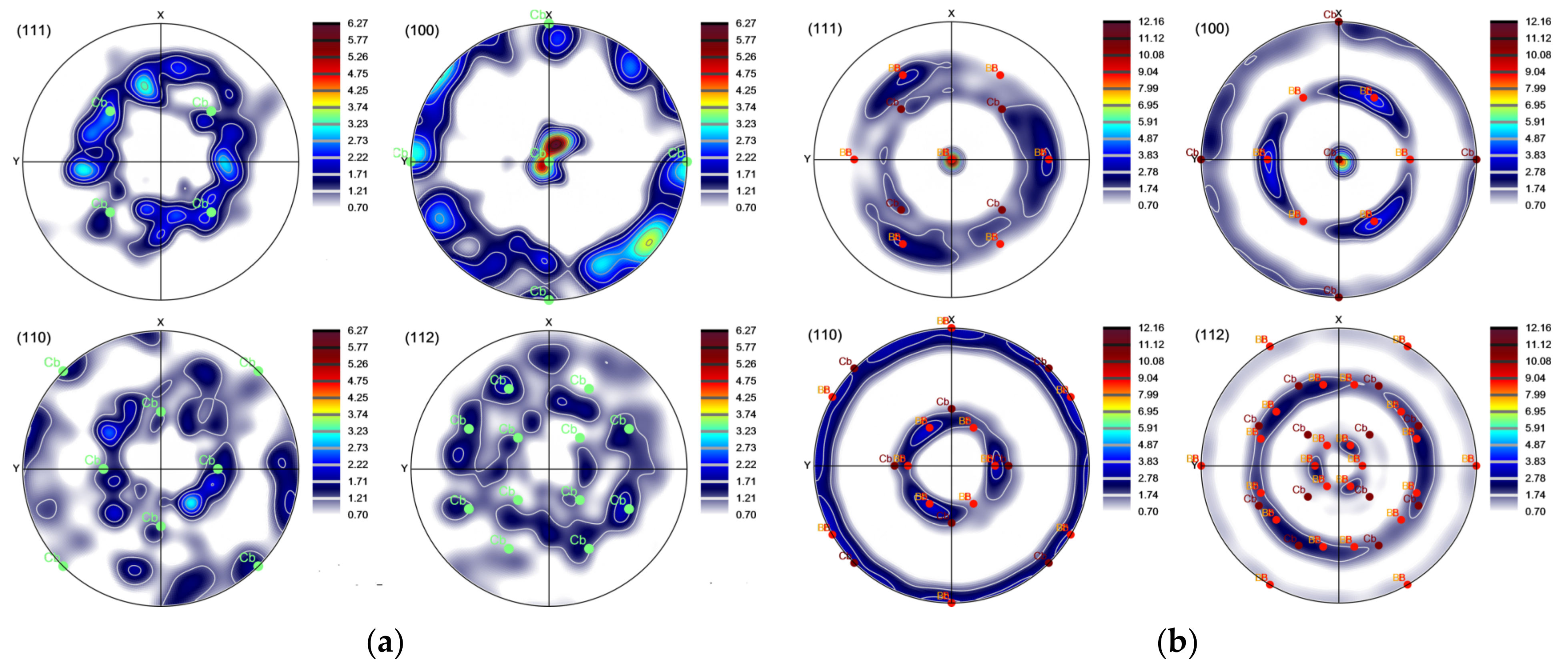
4.2. Texture Analysis

As shown in Figure 5, the grains of the AlSi10Mg alloy show preferred crystallographic orientations. In the case of the LPBF state, the majority of grains have a strong texture along (100) direction, Figure 5a. The (100), (110), (111) and (112) pole figures, Figure 14a confirm that the ⟨100⟩ cube texture is the predominant in the LPBF condition, which is typical for LPBF Al–Si alloys [53,54].
Previous study [55] demonstrated that severe cyclic torsion in KoBo extrusion process can induce the development of a strong texture characterised by the presence of intense poles corresponding to specific orientations of crystallites. As can be seen in Figure 14b, the texture of the AlSi10Mg alloy subjected to KoBo extrusion is consistent with the models of the authors of the manuscript cited above. A great majority of the crystallites display (111) and (100) orientations, corresponding to ⟨111⟩ and ⟨001⟩ fibre-type texture components. Moreover, it is evident that certain crystallites exhibit a weak cube texture, which is indicative of the recrystallisation process [56].
The recrystallisation texture displays an axial pattern, which can be attributed to the formation of recrystallisation growth nuclei with orientations near ⟨100⟩ and ⟨111⟩ in the deformed grains exhibiting corresponding orientations. These nuclei grow within the surrounding deformed matrix when their misorientation with the neighbouring area aligns at an angle close to 52° around one of the crystallographic axes, specifically ⟨331⟩ [41]. As a result, the misorientation closely approximates the CSL (Coincidence Site Lattice) misorientation Σ25b (see Figure 8b).

5. Conclusions

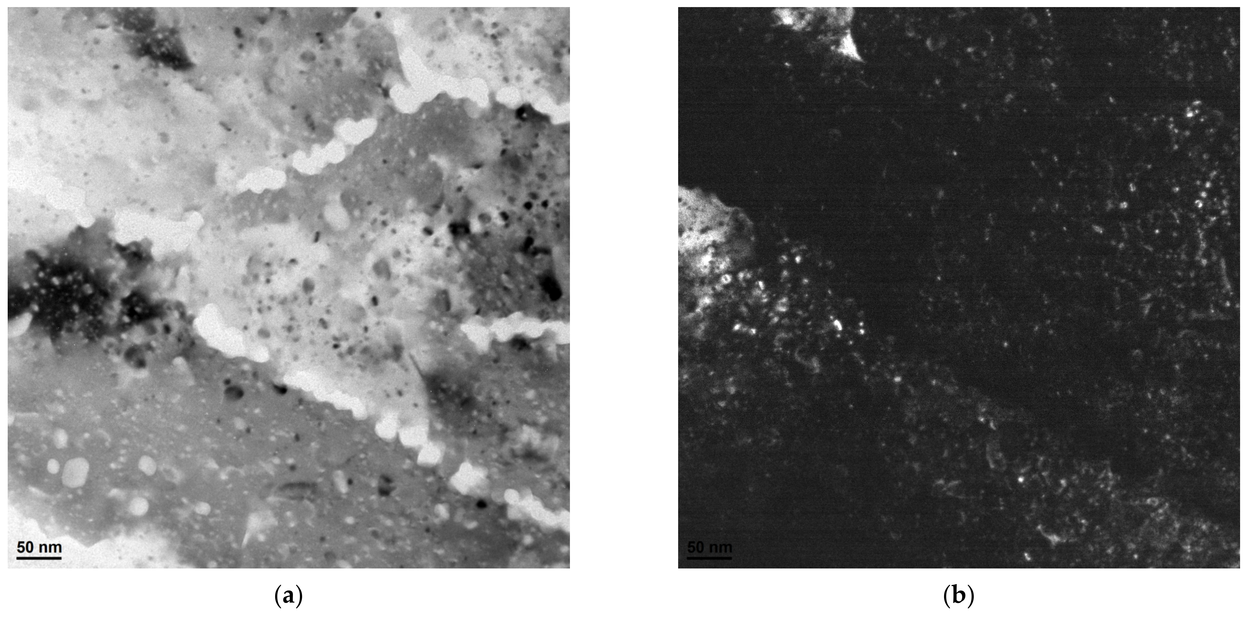
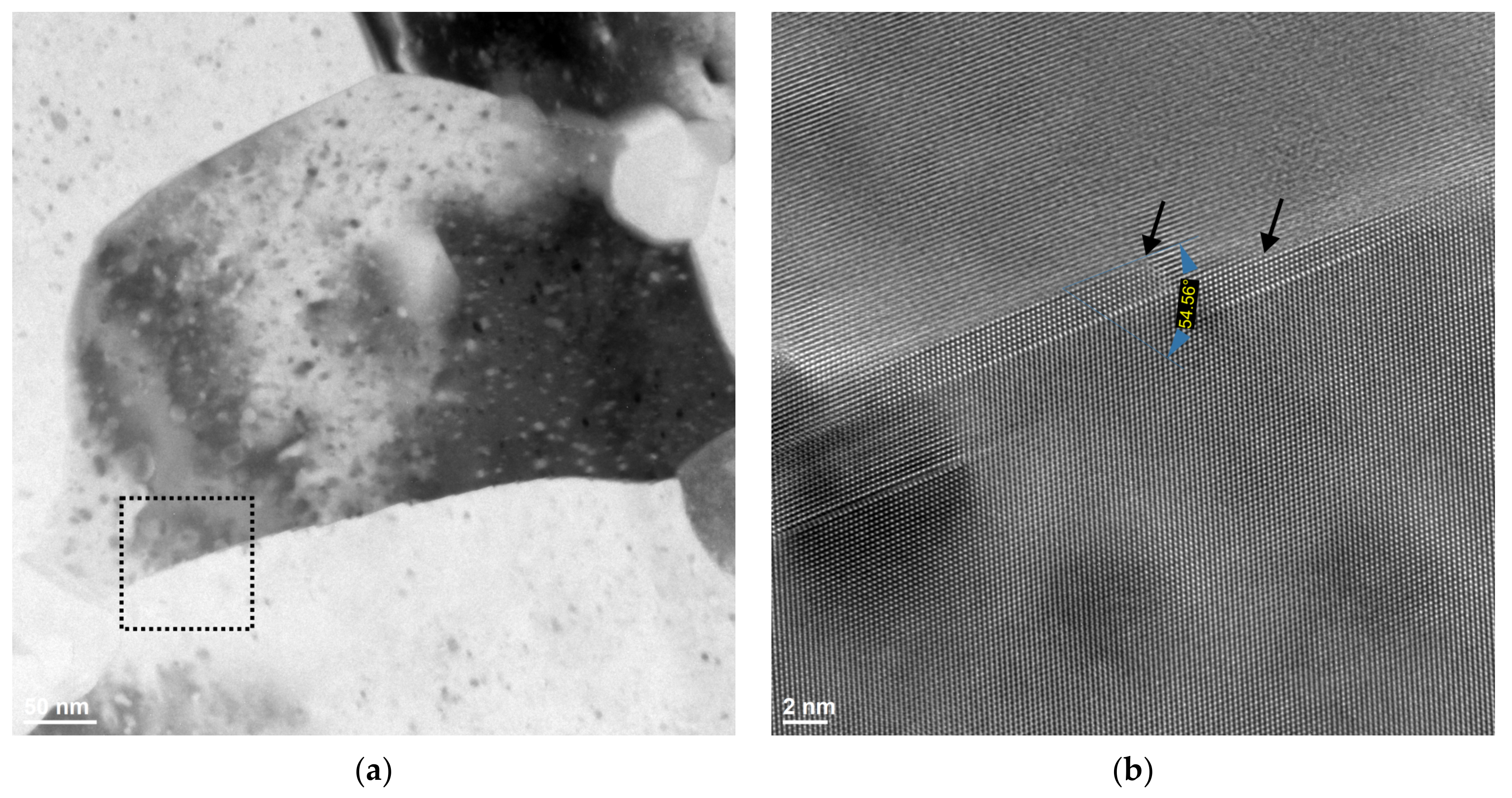
  • The KoBo extrusion process substantially refined the heterogeneous microstructure of an LPBF AlSi10Mg aluminium alloy. Also, the cellular microstructure diminished and was replaced by the fine Si precipitates distributed uniformly within the aluminium matrix.
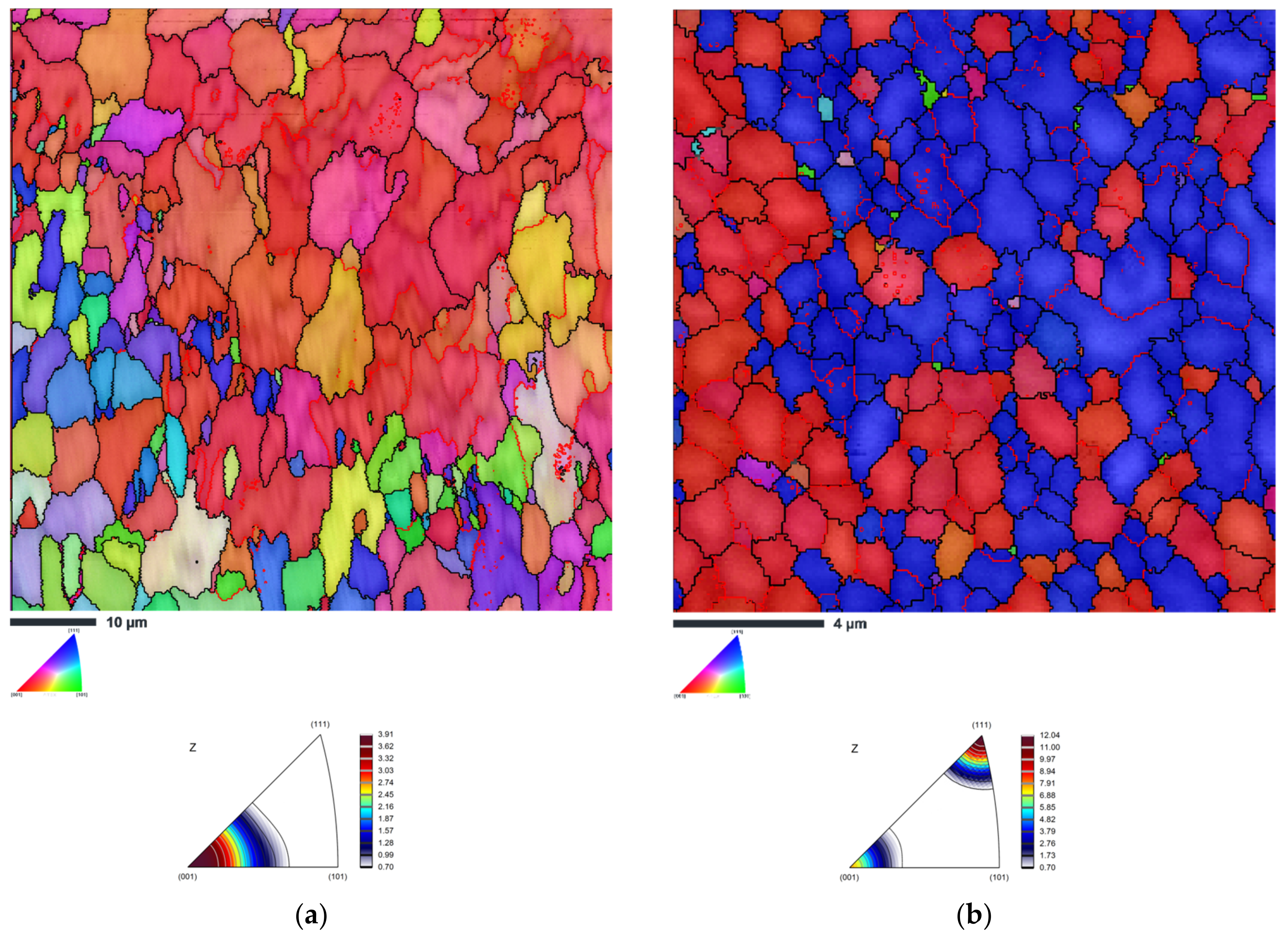
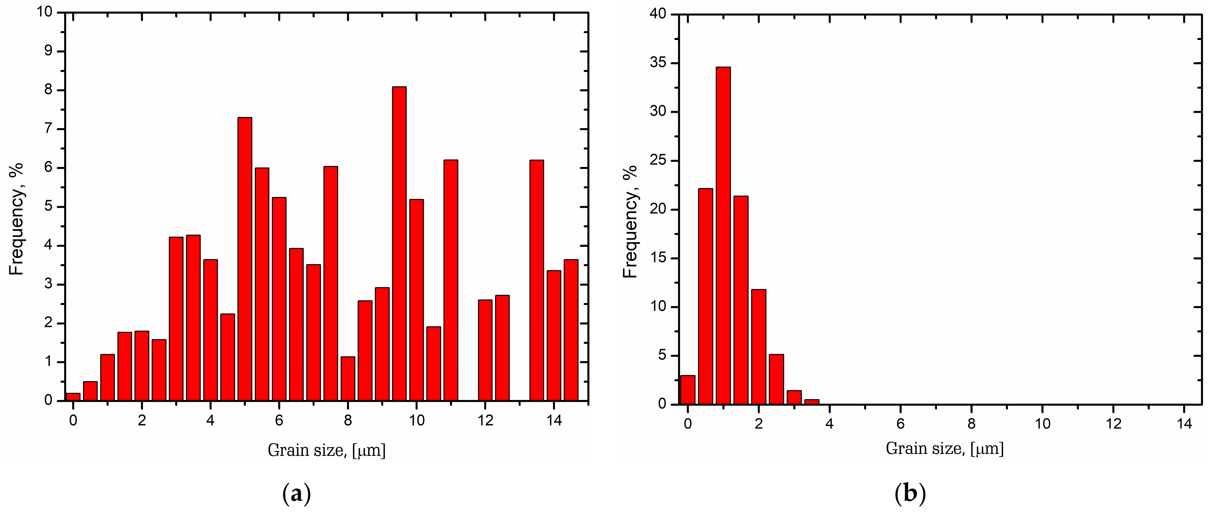
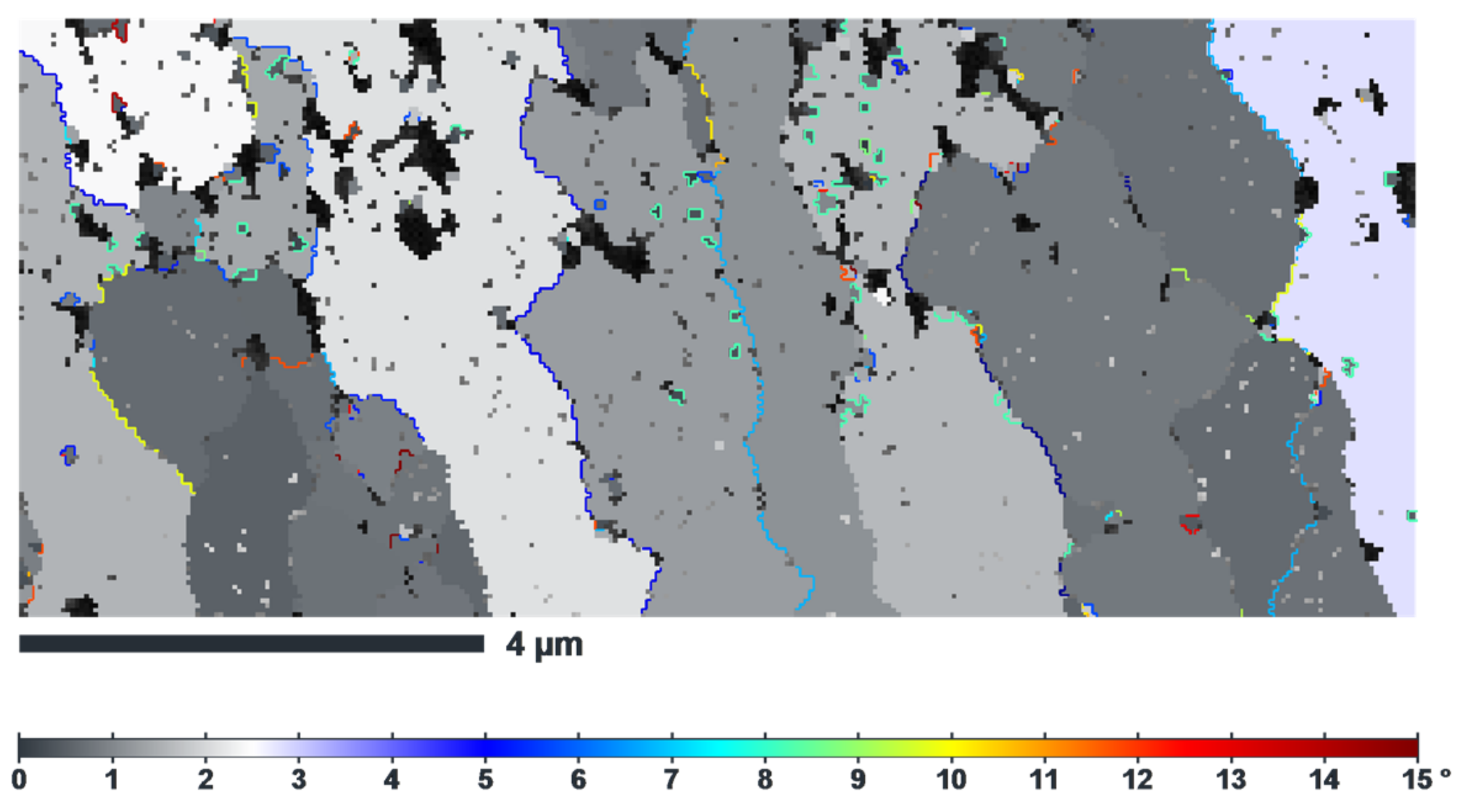
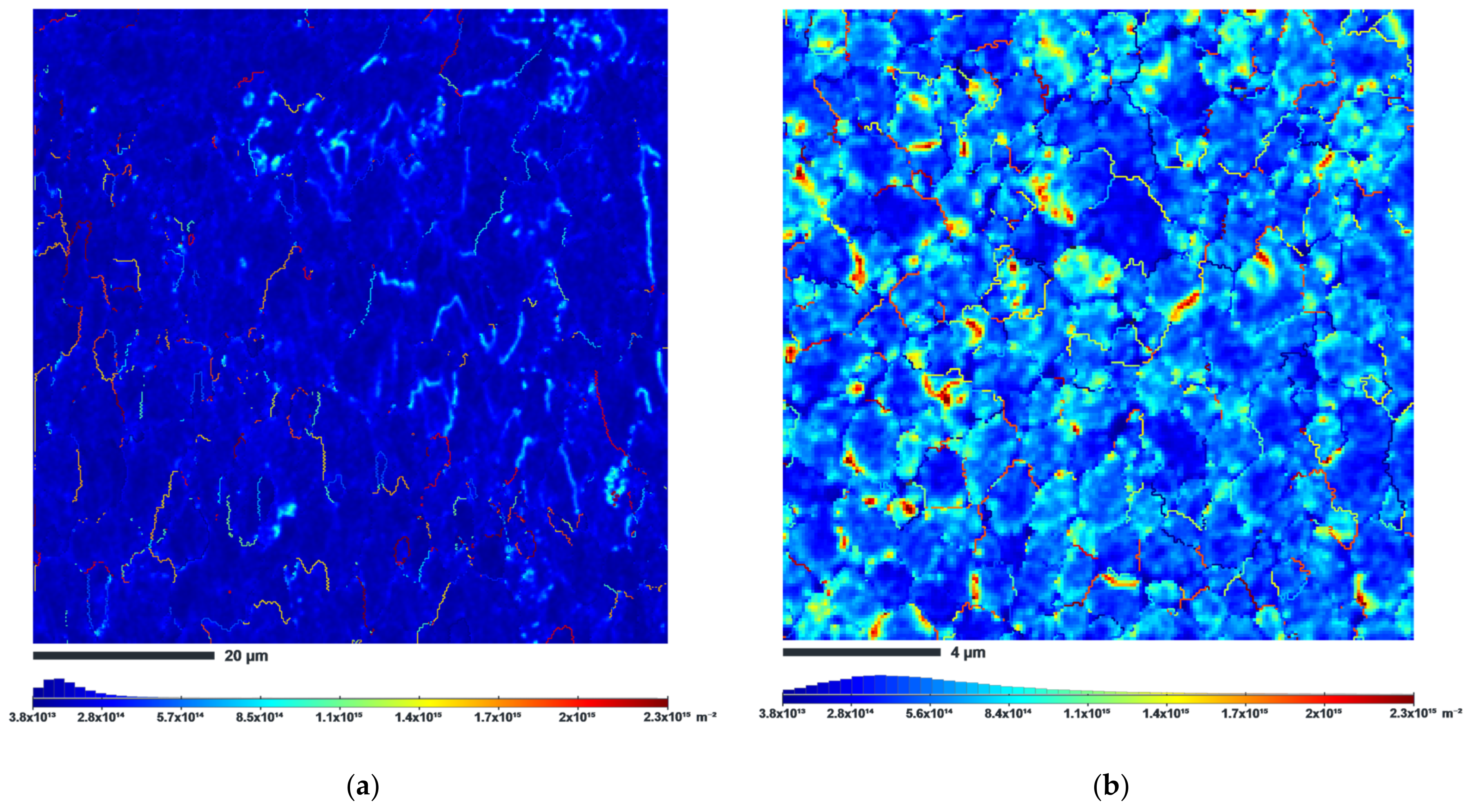
  • The microstructure of the LPBF material underwent significant refinement as a result of the KoBo extrusion process, reducing the grain size to the sub-micrometric level. The study revealed that the KoBo sample displayed an average grain size of 1.1 µm. This refined microstructure is expected to have a substantial impact on the material’s properties.
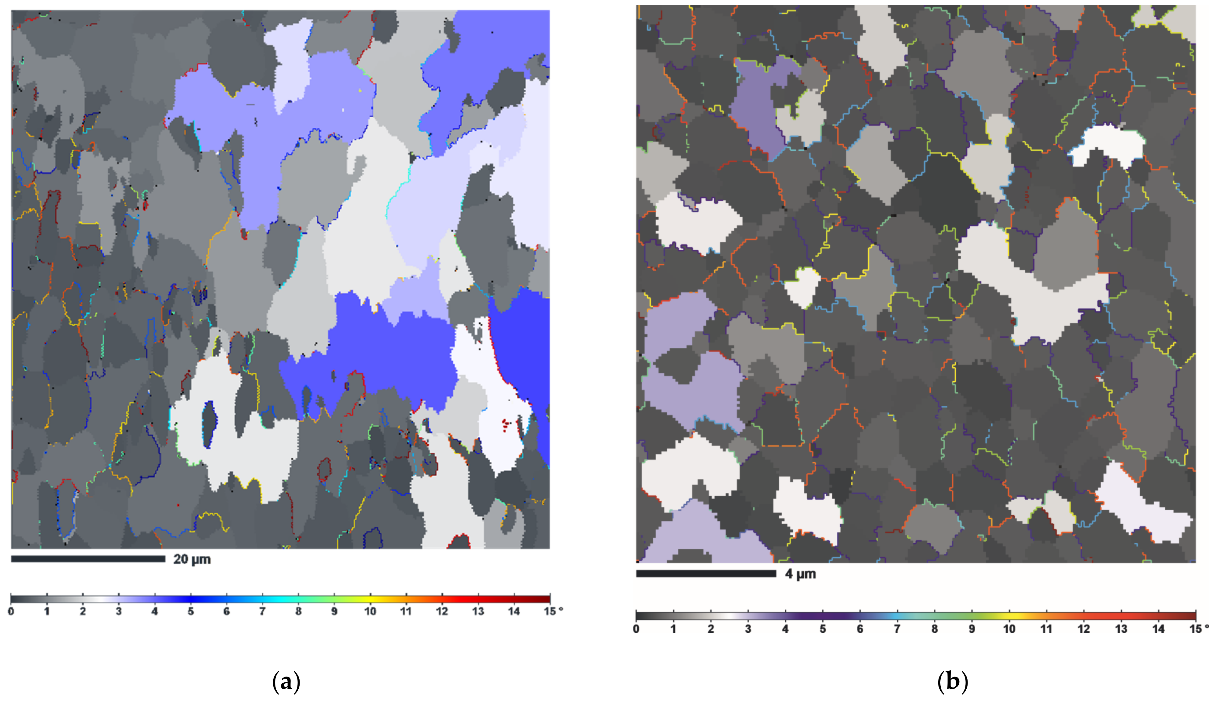
  • The KoBo extrusion process led to a severe increment of the high-angle grain boundary population, indicating the dynamic recrystallisation process.
  • The analyses of the IPF images revealed grains oriented along the ⟨111⟩ and ⟨001⟩ axes and a high number of recrystallised grains with a near {111} ⟨112⟩ orientation.
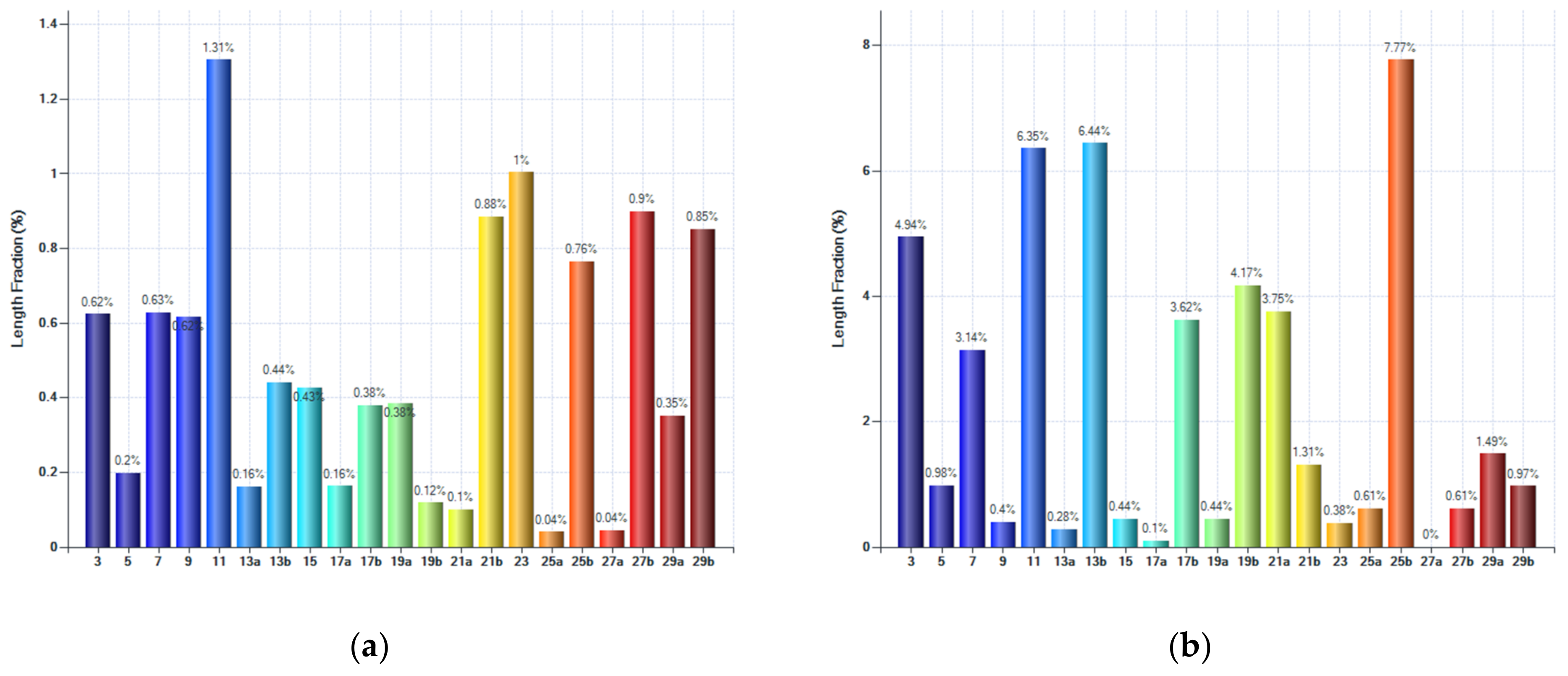
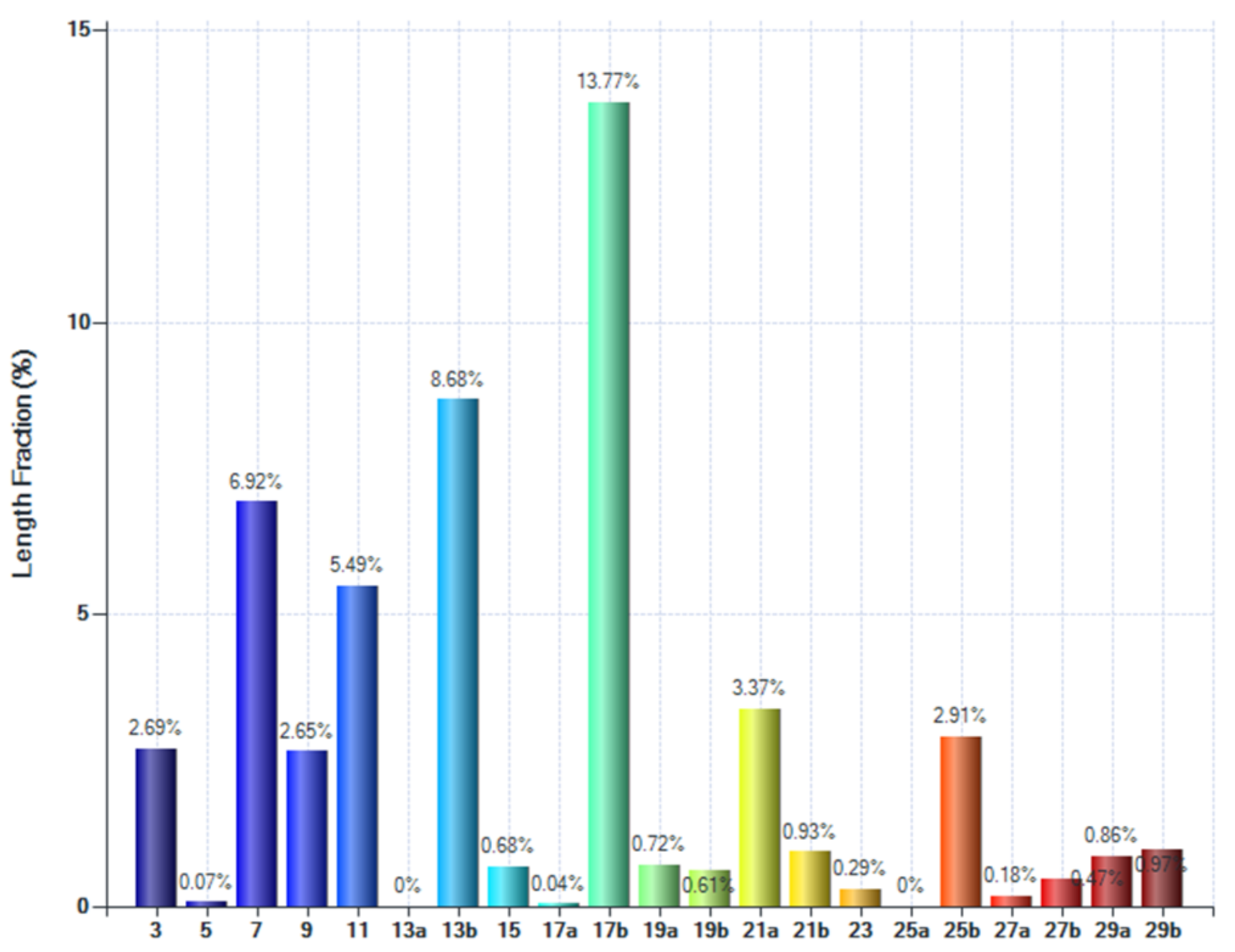
  • High-strain and high-rate deformation post-processing of the LPBF AlSi10Mg alloy resulted in a grain-boundary-engineered microstructure, as evidenced by increased length fractions of the Σ3, Σ7 and Σ11 boundaries. It was found that the fraction of CSL boundaries increases after the KoBo extrusion process.

Author Contributions

P.S.: conceptualization, methodology, validation, formal analysis, resources, data curation, writing—original draft, visualization, supervision, project administration, founding acquisition; K.M.: data curation, formal analysis. P.S. contributed 85% of the research work, primarily by conducting the KoBo experiments, microstructural analysis, data collection, data analysis, project administration and writing of the manuscript; K.M. contributed 15% of research work, primarily by conducting the microstructural analysis. All authors have read and agreed to the published version of the manuscript.

Funding

The research was funded by the National Science Centre, Poland, based on the decision number 2021/43/D/ST8/01946.

Institutional Review Board Statement

Not applicable.

Informed Consent Statement

Not applicable.

Data Availability Statement

Data available on request.

Conflicts of Interest

The authors declare no conflict of interest.

References

  1. Jiang, Y.; Moubayidin, L. Floral symmetry: The geometry of plant reproduction. Emerg. Top. Life Sci. 2022, 6, 259–269. [Google Scholar] [CrossRef] [PubMed]
  2. Wu, X.; Knuth, M.J.; Hall, C.R.; Palma, M.A. Increasing Profit Margins by Substituting Species in Floral Arrangements. Horttechnology 2021, 31, 19–26. [Google Scholar] [CrossRef]
  3. Zhao, P.; Zhang, K.; Zhao, C.; Qi, L.; Deng, Z. In-plane wave propagation analysis for waveguide design of hexagonal lattice with Koch snowflake. Int. J. Mech. Sci. 2021, 209, 106724. [Google Scholar] [CrossRef]
  4. Snyder, M.; Kara, M. A Modeling Activity: Analyzing Snowflakes Using Geometry. Ohio J. Sch. Math. 2022, 92, 1–7. [Google Scholar]
  5. Pignataro, T.; Lourenço, G.M.; Beirão, M.; Cornelissen, T. Wings are not perfect: Increased wing asymmetry in a tropical butterfly as a response to forest fragmentation. Sci. Nat. 2023, 110, 28. [Google Scholar] [CrossRef] [PubMed]
  6. Shamir, L. Using Machine Learning to Profile Asymmetry between Spiral Galaxies with Opposite Spin Directions. Symmetry 2022, 14, 934. [Google Scholar] [CrossRef]
  7. Lovell, T.C.; Colwell, C.E.; Zakharov, L.N.; Jasti, R. Symmetry breaking and the turn-on fluorescence of small, highly strained carbon nanohoops. Chem. Sci. 2019, 10, 3786–3790. [Google Scholar] [CrossRef]
  8. Votano, J.; Parham, M.; Hall, L. Handbook of Aluminum Volume 2 Alloy Production and Material Manufacturing; CRC Press: Boca Raton, FL, USA, 2004; pp. 1–731. [Google Scholar]
  9. Gargeya, B.S.K.; Babu, P.N.; Pal, S. Constant twist rate response of symmetric and asymmetric Σ5 aluminium tilt grain boundaries: Molecular dynamics study of deformation processes. J. Mater. Sci. 2021, 56, 8544–8562. [Google Scholar] [CrossRef]
  10. Tschopp, M.A.; Coleman, S.P.; McDowell, D.L. Symmetric and asymmetric tilt grain boundary structure and energy in Cu and Al (and transferability to other fcc metals). Integr. Mater. Manuf. Innov. 2015, 4, 176–189. [Google Scholar] [CrossRef]
  11. Mishin, Y.; Asta, M.; Li, J. Atomistic modeling of interfaces and their impact on microstructure and properties. Acta Mater. 2010, 58, 1117–1151. [Google Scholar] [CrossRef]
  12. Zhang, C.; Lin, L.; Chen, R.; Zhang, L.; Shao, Z. Grain Boundary Engineering and Its Effect on Intergranular Corrosion Resistance of a Ni-Cr-Mo Based C276 Superalloy. Crystals 2022, 12, 1625. [Google Scholar] [CrossRef]
  13. Dolzhenko, P.; Tikhonova, M.; Odnobokova, M.; Kaibyshev, R.; Belyakov, A. On Grain Boundary Engineering for a 316L Austenitic Stainless Steel. Metals 2022, 12, 2185. [Google Scholar] [CrossRef]
  14. Laleh, M.; Hughes, A.E.; Tan, M.Y.; Rohrer, G.S.; Primig, S.; Haghdadi, N. Grain boundary character distribution in an additively manufactured austenitic stainless steel. Scr. Mater. 2021, 192, 115–119. [Google Scholar] [CrossRef]
  15. Randle, V. Relationship between coincidence site lattice, boundary plane indices, and boundary energy in nickel. Mater. Sci. Technol. 1999, 15, 246–252. [Google Scholar] [CrossRef]
  16. Jiang, X.; Yang, C.; Zhang, W.; Wang, X. Surface grain boundary engineering in 304 stainless steel by means of mechanical grinding treatment-induced gradient plastic strain and annealing. J. Mater. Sci. 2022, 57, 21798–21812. [Google Scholar] [CrossRef]
  17. Guan, X.J.; Shi, F.; Jia, Z.P.; Li, X.W. Grain boundary engineering of AL6XN super-austenitic stainless steel: Distinctive effects of planar-slip dislocations and deformation twins. Mater. Charact. 2020, 170, 110689. [Google Scholar] [CrossRef]
  18. Chen, X.-H.; Wang, F.; Zhang, F. Grain boundary engineering process for nano reinforced aluminum matrix composites. J. Alloys Compd. 2023, 939, 168834. [Google Scholar] [CrossRef]
  19. Shi, Z.; He, R.; Chen, Y.; Yan, H.; Song, H.; Luo, C.; Nie, Q.; Hu, Z. Microstructural evolution and strengthening mechanisms of a novel Al–11Si–3Cu alloy microalloyed with minor contents of Sr and Sc. Mater. Sci. Eng. A 2022, 853, 143738. [Google Scholar] [CrossRef]
  20. Richter, N.A.; Zhang, Y.F.; Xie, D.Y.; Su, R.; Li, Q.; Xue, S.; Niu, T.; Wang, J.; Wang, H.; Zhang, X. Microstructural evolution of nanotwinned Al-Zr alloy with significant 9R phase. Mater. Res. Lett. 2021, 9, 91–98. [Google Scholar] [CrossRef]
  21. Liu, M.; Wang, P.; Lu, G.; Huang, C.-Y.; You, Z.; Wang, C.-H.; Yen, H.-W. Deformation-activated recrystallization twin: New twinning path in pure aluminum enabled by cryogenic and rapid compression. iScience 2022, 25, 104248. [Google Scholar] [CrossRef]
  22. Guo, B.; Song, M.; Zhang, X.; Liu, Y.; Cen, X.; Chen, B.; Li, W. Exploiting the synergic strengthening effects of stacking faults in carbon nanotubes reinforced aluminum matrix composites for enhanced mechanical properties. Compos. Part B Eng. 2021, 211, 108646. [Google Scholar] [CrossRef]
  23. Gong, D.; Cao, Y.; Deng, X.; Jiang, L. Higher proportional limit of SiC/Al composites with nano-scaled stacking faults. Compos. Commun. 2022, 32, 101188. [Google Scholar] [CrossRef]
  24. Xue, S.; Fan, Z.; Lawal, O.B.; Thevamaran, R.; Li, Q.; Liu, Y.; Yu, K.Y.; Wang, J.; Thomas, E.L.; Wang, H.; et al. High-velocity projectile impact induced 9R phase in ultrafine-grained aluminium. Nat. Commun. 2017, 8, 1653. [Google Scholar] [CrossRef] [PubMed]
  25. Xiong, Q.; Li, Z.; Huang, X.; Shimada, T.; Kitamura, T. Thermomechanical conversion in high-rate plastic deformation of nanotwinned polycrystalline copper. J. Therm. Stress. 2022, 45, 65–80. [Google Scholar] [CrossRef]
  26. Qian, L.; Cui, Z.; Sun, C.; Geng, S.; Sun, Z. Investigation of deformation compatibility and power consumption during KOBO extrusion of bimetallic composite tube. Int. J. Adv. Manuf. Technol. 2022, 118, 3477–3486. [Google Scholar] [CrossRef]
  27. Valiev, R.Z.; Langdon, T.G. Principles of equal-channel angular pressing as a processing tool for grain refinement. Prog. Mater. Sci. 2006, 51, 881–981. [Google Scholar] [CrossRef]
  28. Snopiński, P.; Matus, K.; Tatiček, F.; Rusz, S. Overcoming the strength-ductility trade-off in additively manufactured AlSi10Mg alloy by ECAP processing. J. Alloys Compd. 2022, 918, 165817. [Google Scholar] [CrossRef]
  29. Snopiński, P.; Król, M.; Pagáč, M.; Petrů, J.; Hajnyš, J.; Mikuszewski, T.; Tański, T. Effects of equal channel angular pressing and heat treatments on the microstructures and mechanical properties of selective laser melted and cast AlSi10Mg alloys. Arch. Civ. Mech. Eng. 2021, 21, 92. [Google Scholar] [CrossRef]
  30. Zhilyaev, A.P.; Langdon, T.G. Using high-pressure torsion for metal processing: Fundamentals and applications. Prog. Mater. Sci. 2008, 53, 893–979. [Google Scholar] [CrossRef]
  31. Tsuji, N.; Saito, Y.; Lee, S.-H.; Minamino, Y. ARB (Accumulative Roll-Bonding) and other new Techniques to Produce Bulk Ultrafine Grained Materials. Adv. Eng. Mater. 2003, 5, 338–344. [Google Scholar] [CrossRef]
  32. Korbel, A.; Błaż, L.; Bochniak, W.; Pawlyta, M.; Ostachowski, P.; Łagoda, M. Nano-Dimensional Elements in the Structure of Zinc Subjected to KOBO Extrusion. Met. Microstruct. Anal. 2023, 12, 427–432. [Google Scholar] [CrossRef]
  33. Dai, C.; Saidi, P.; Yao, Z.; Béland, L.K.; Daymond, M.R. Deformation-free nanotwin formation in zirconium and titanium. Mater. Lett. 2019, 247, 111–114. [Google Scholar] [CrossRef]
  34. Bai, F.M.; Ye, X.; Zhang, H.Y.; Zhou, H.W.; Song, M.; Sun, Y.X.; He, Y.Z. A significant increase in the hardness of nanotwinned titanium alloys prepared via the martensitic phase transformation. Mater. Lett. 2019, 255, 126507. [Google Scholar] [CrossRef]
  35. Bochniak, W.; Marszowski, K.; Korbel, A. Theoretical and practical aspects of the production of thin-walled tubes by the KOBO method. J. Mater. Process. Technol. 2005, 169, 44–53. [Google Scholar] [CrossRef]
  36. Beausir, B.; Fundenberger, J.J. Analysis Tools for Electron and X-ray Diffraction, ATEX–Software; Université de Lorraine-Metz: Nancy, France, 2007. [Google Scholar]
  37. Rafieazad, M.; Mohammadi, M.; Nasiri, A.M. On microstructure and early stage corrosion performance of heat treated direct metal laser sintered AlSi10Mg. Addit. Manuf. 2019, 28, 107–119. [Google Scholar] [CrossRef]
  38. Thijs, L.; Kempen, K.; Kruth, J.P.; Van Humbeeck, J. Fine-structured aluminium products with controllable texture by selective laser melting of pre-alloyed AlSi10Mg powder. Acta Mater. 2013, 61, 1809–1819. [Google Scholar] [CrossRef]
  39. Ding, C.; Hao, H.; Lu, Z.; Yu, C.; Wu, X.; Yu, P.; Ye, S. Fabrication of hypereutectic Al–Si alloy with improved mechanical and thermal properties by hot extrusion. Mater. Charact. 2023, 202, 113026. [Google Scholar] [CrossRef]
  40. Nittala, A.; Smith, J.; Gwalani, B.; Silverstein, J.; Kraft, F.F.; Kappagantula, K. Simultaneously improved electrical and mechanical performance of hot-extruded bulk scale aluminum-graphene wires. Mater. Sci. Eng. B 2023, 293, 116452. [Google Scholar] [CrossRef]
  41. Danilov, S.V.; Reznik, P.L.; Zorina, M.A.; Lobanov, M.L. Effect of special boundaries on recrystallization texture of FCC metals with high packing defect energy. AIP Conf. Proc. 2019, 2174, 20207. [Google Scholar] [CrossRef]
  42. Jones, R.; Randle, V. Sensitisation behaviour of grain boundary engineered austenitic stainless steel. Mater. Sci. Eng. A 2010, 527, 4275–4280. [Google Scholar] [CrossRef]
  43. Fang, Z.; Xiao, J.; Tan, S.; Deng, C.; Wang, G.; Mao, S.X. Atomic-scale observation of dynamic grain boundary structural transformation during shear-mediated migration. Sci. Adv. 2023, 8, eabn3785. [Google Scholar] [CrossRef] [PubMed]
  44. Oda, S.; Tanaka, S.-I. Grain boundaries with high Σ value and strain in grain matrix induce crack initiation in extruded 6000 series aluminium alloys. Mater. Sci. Eng. A 2022, 834, 142630. [Google Scholar] [CrossRef]
  45. Cao, Y.; Di, H.; Zhang, J.; Zhang, J.; Ma, T.; Misra, R.D.K. An electron backscattered diffraction study on the dynamic recrystallization behavior of a nickel–chromium alloy (800H) during hot deformation. Mater. Sci. Eng. A 2013, 585, 71–85. [Google Scholar] [CrossRef]
  46. Mandal, S.; Jayalakshmi, M.; Bhaduri, A.K.; Subramanya Sarma, V. Effect of Strain Rate on the Dynamic Recrystallization Behavior in a Nitrogen-Enhanced 316L(N). Met. Mater. Trans. A 2014, 45, 5645–5656. [Google Scholar] [CrossRef]
  47. Zhu, R.J.; Zhou, X.; Li, X.Y. Thermal stability of nanograins with grain boundary relaxation in microalloyed Cu-Sb and Cu-Fe. J. Mater. Sci. Technol. 2023, 155, 66–71. [Google Scholar] [CrossRef]
  48. Muzyk, M.; Pakiela, Z.; Kurzydlowski, K.J. Ab initio calculations of the generalized stacking fault energy in aluminium alloys. Scr. Mater. 2011, 64, 916–918. [Google Scholar] [CrossRef]
  49. Garcia-Chao, P.; Eipe, J.J.; Krugla, M.; Bos, C.; Sietsma, J.; Kranendonk, W.; Offerman, S.E. Nucleation Sites in the Static Recrystallization of a Hot-Deformed Ni-30 Pct Fe Austenite Model Alloy. Met. Mater. Trans. A 2023, 54, 2160–2177. [Google Scholar] [CrossRef]
  50. Detrois, M.; McCarley, J.; Antonov, S.; Helmink, R.C.; Goetz, R.L.; Tin, S. Comparative study of high-temperature grain boundary engineering of two powder-processed low stacking-fault energy Ni-base superalloys. Mater. High Temp. 2016, 33, 310–317. [Google Scholar] [CrossRef]
  51. Sarkari Khorrami, M.; Saito, N. On the formation of large grain structure after friction stir processing of ultrafine-grained aluminium alloy. Philos. Mag. 2023, 103, 733–748. [Google Scholar] [CrossRef]
  52. Min, K.M.; Jeong, W.; Hong, S.H.; Lee, C.A.; Cha, P.-R.; Han, H.N.; Lee, M.-G. Integrated crystal plasticity and phase field model for prediction of recrystallization texture and anisotropic mechanical properties of cold-rolled ultra-low carbon steels. Int. J. Plast. 2020, 127, 102644. [Google Scholar] [CrossRef]
  53. Zhao, L.; Song, L.; Santos Macías, J.G.; Zhu, Y.; Huang, M.; Simar, A.; Li, Z. Review on the correlation between microstructure and mechanical performance for laser powder bed fusion AlSi10Mg. Addit. Manuf. 2022, 56, 102914. [Google Scholar] [CrossRef]
  54. Sathishkumar, A.; Soundararajan, R.; Sivasankaran, S. Effect of Direct Aging on the Microstructure and Mechanical Behavior of AlSi10Mg Alloy: Casting Versus Selective Laser Melting. J. Mater. Eng. Perform. 2023, 32, 3215–3229. [Google Scholar] [CrossRef]
  55. Kowalczyk-Gajewska, K.; Stupkiewicz, S. Modelling of Texture Evolution in Kobo Extrusion Process/Modelowanie Rozwoju Tekstury W Procesie Wyciskania Metoda Kobo. Arch. Metall. Mater. 2013, 58, 113–118. [Google Scholar] [CrossRef]
  56. Lee, D.N.; Han, H.N. Recrystallization Textures of Metals and Alloys; Wilson, P., Ed.; IntechOpen: Rijeka, Croatia, 2013; Chapter 1. [Google Scholar]
Figure 1. SEM image of the AlSi10Mg alloy powder used in this study and corresponding particle size distribution measurement.
Symmetry 15 01634 g001
Figure 2. LM microstructures of the AlSi10Mg alloy (a) in the LPBF condition, (b) after the KoBo extrusion process (note that, in (a), the laser scan track boundaries are visible as the brighter areas).
Symmetry 15 01634 g002
Figure 3. SEM microstructures of the AlSi10Mg alloy (a) in the LPBF condition, (b) after KoBo extrusion process (note that (a) shows the microstructure on the “build x–y plane”, whereas (b) shows the microstructure on the “extrusion ND–TD plane”).
Symmetry 15 01634 g003
Figure 4. Results of SEM EDS pointwise chemical composition analysis. (a) EDS spectrum corresponding to the point (1) in Figure 3b. (b) EDS spectrum corresponding to point (2) in Figure 3b.
Symmetry 15 01634 g004
Figure 5. Results of the EBSD analysis. IPF-Z images of AlSi10Mg alloy (a) in the LPBF condition, (b) after KoBo extrusion process (red and blue colours represent the <001> and <111> fibres, respectively).
Symmetry 15 01634 g005
Figure 6. Histograms of grain size distribution of the AlSi10Mg alloy (a) in the LPBF condition, (b) after KoBo extrusion process.
Symmetry 15 01634 g006
Figure 7. The GOS maps of AlSi10Mg alloy (a) in the LPBF condition, (b) after KoBo extrusion process (note that in the GOS maps the CSL boundaries are shown with different colours).
Symmetry 15 01634 g007
Figure 8. The distribution of boundary types with respect to Σ of AlSi10Mg alloy (a) in the LPBF condition, (b) after KoBo extrusion process.
Symmetry 15 01634 g008
Figure 9. The TKD map of AlSi10Mg alloy showing GOS and CSL boundaries in KoBo sample.
Symmetry 15 01634 g009
Figure 10. The distribution of boundary types with respect to Σ of AlSi10Mg alloy after KoBo extrusion process (note that this image presents the result of CSL boundary analysis received from TKD analysis).
Symmetry 15 01634 g010
Figure 11. Microstructure of AlSi10Mg alloy in LPBF condition. (a) Bright-field TEM image. (b) Dark-field TEM image.
Symmetry 15 01634 g011
Figure 12. Microstructure of AlSi10Mg alloy subjected to KoBo extrusion. (a) Bright-field TEM image. (b) HRTEM image of the boundary area highlighted in (a).
Symmetry 15 01634 g012
Figure 13. GND distribution maps (a) in the LPBF condition, (b) after KoBo extrusion process.
Symmetry 15 01634 g013
Figure 14. Pole figures of the AlSi10Mg alloy (a) in LPBF condition, (b) after KoBo extrusion process.
Symmetry 15 01634 g014
Table 1. Chemical composition of the AlSi10Mg alloy powder.
AlMgSiTiCuFe
87.80.510.50.150.150.09
Table 2. Averaged results of microstructural analysis conducted with SEM microscope (on the basis of three separate scans).
ConditionLAGBsHAGBsGrain Size, µmRecrystallised Fraction, %
(Grains with GOS < 2.5°)
Geometrically Necessary Dislocation Density, m−2
LPBF22.8 ± 1.777.2 ± 1.26.3 ± 0.392.6 ± 2.11.79 × 1014
KoBo9.2 ± 1.390.8 ± 0.81.1 ± 0.293.5 ± 1.56.20 × 1014
Disclaimer/Publisher’s Note: The statements, opinions and data contained in all publications are solely those of the individual author(s) and contributor(s) and not of MDPI and/or the editor(s). MDPI and/or the editor(s) disclaim responsibility for any injury to people or property resulting from any ideas, methods, instructions or products referred to in the content.

