Article

Design, Simulation and Experimental Evaluation of Hot-Stamped 22MnB5 Steel Autobody Part

1
Department of Engineering Materials and Biomaterials, Silesian University of Technology, 18A Konarskiego Street, 44-100 Gliwice, Poland
2
Faculty of Mechanical Engineering and Computer Science, University of Bielsko-Biala, Willowa 2 Street, 43-309 Bielsko-Biala, Poland
*
Author to whom correspondence should be addressed.
Symmetry 2022, 14(12), 2625; https://doi.org/10.3390/sym14122625
Submission received: 12 November 2022 / Revised: 29 November 2022 / Accepted: 6 December 2022 / Published: 12 December 2022
(This article belongs to the Special Issue Advances in Metallic Material and Symmetry/Asymmetry)

Abstract

:
The combination of complex geometry and martensitic microstructure, characterized by ultrahigh strength and hardness, can be obtained in a single hot stamping process. However, this technology requires a multifaceted approach, allowing for an effective and efficient design process that will ensure the elements with the desired properties and shape are produced because of the high tool cost. This paper presents a comprehensive case study of the design process, simulation and experimental evaluation of the hot forming of an automotive door beam. The U-shaped beam designed with CAD was analyzed using the finite element method in the Autoform v.10 software. The modeling process included: a shape definition of the flat blank; a FEM analysis and design of the die, punches, and clamps; and a forming and quenching simulation. The results covered visualization of the forming and quenching stages for different variables including a forming limit diagram; a distribution of the drawpiece thinning; and a diagram showing the hardness of the drawpiece and its microstructure. Based on the results, a full-size tool for hot stamping was first modeled in the CAD and next manufactured. The tool was used to produce an initial sample series that was used to investigate the conditions for continuous use of the tool. One of the produced hot-stamped products was investigated for its hardness and microstructure, which exhibited a beneficial and fully martensitic microstructure with high hardness of above 400 HV1.

1. Introduction

Reduced fuel consumption and continuous passenger safety improvements are the main objectives for modern vehicle producers in the automotive industry [1]. Both objectives can be obtained by the introduction of advanced high-strength steels (AHSS) and structures of advanced geometry. The former increases yield strength (YS) and ultimate tensile strength (UTS) of the material, whereas the latter improves stiffness and toughness [2,3,4]. Such autobody parts can be produced first by using conventional stamping from steel sheets when the material is ductile and subsequently by using a heat treatment to improve the strength and hardness. However, this requires the use of two technological processes, which results in significant costs.
Hot stamping is a technology that allows for the integration of the conventional stamping and heat treatment processes [5,6]. The material, which is typically a 22MnB5 steel blank or a pre-formed element, is austenitized at ~ 920–950 °C as in the typical heat treatment process [7]. The steel sheet is then transferred to the press, where it is formed and cooled at a rate that allows the martensitic transformation to take place (Figure 1). High-temperature pressing allows for a more complex shape to be obtained by lower forces, as the austenitic phase exhibits much better plasticity and ductility, but the product strength is reduced [8]. However, for continuous operation, the mold must have water channels that allow it to maintain a low temperature so that the hardening process can proceed correctly [9]. The final product of hot stamping exhibits a shape–strength relationship, which is currently impossible or very difficult and expensive to obtain using a different method [10].
As shown in Figure 1, the hot stamping process integrates several operations [11]. It is usually fully automated with manipulators or robot arms that are used to transfer elements between the blank pile, furnace, press and finished parts storage [12]. The proper design of the entire process is required to obtain a final product of the desired shape, microstructure and properties regardless of the size and a level of geometric complexity. The process starts with a design of the elements. Next, the die model is prepared, which properly shapes the blank without weakening its structure by excessive thinning. Another very important step is the design of a cooling system. The water channels must be distributed in the die in a way that ensures an adequate cooling rate that is specific for a given shaped product. The hot stamping design process is continuously refined using the latest simulation methods [3,13,14,15]. The comprehensive process design of hot stamping for a specific product is very important for the modern automotive industry and for the advancement of steel applications [2,16,17,18]. Therefore, this paper presents a case study of the design process, simulation and experimental evaluation of the hot forming of an automotive door beam.

2. Materials and Methods

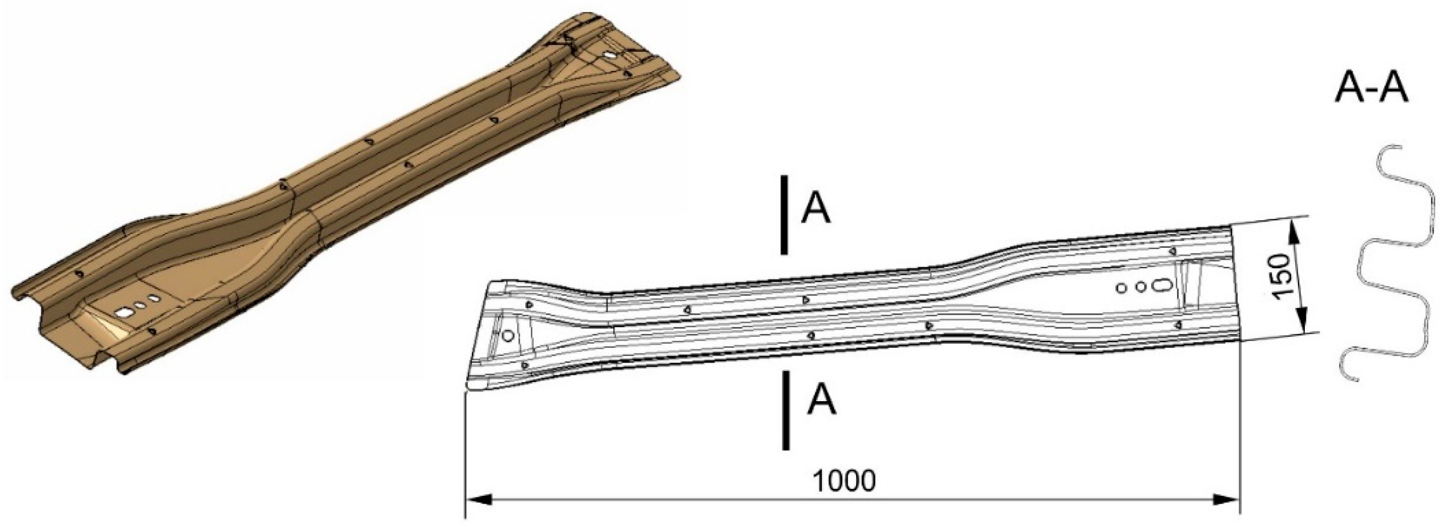
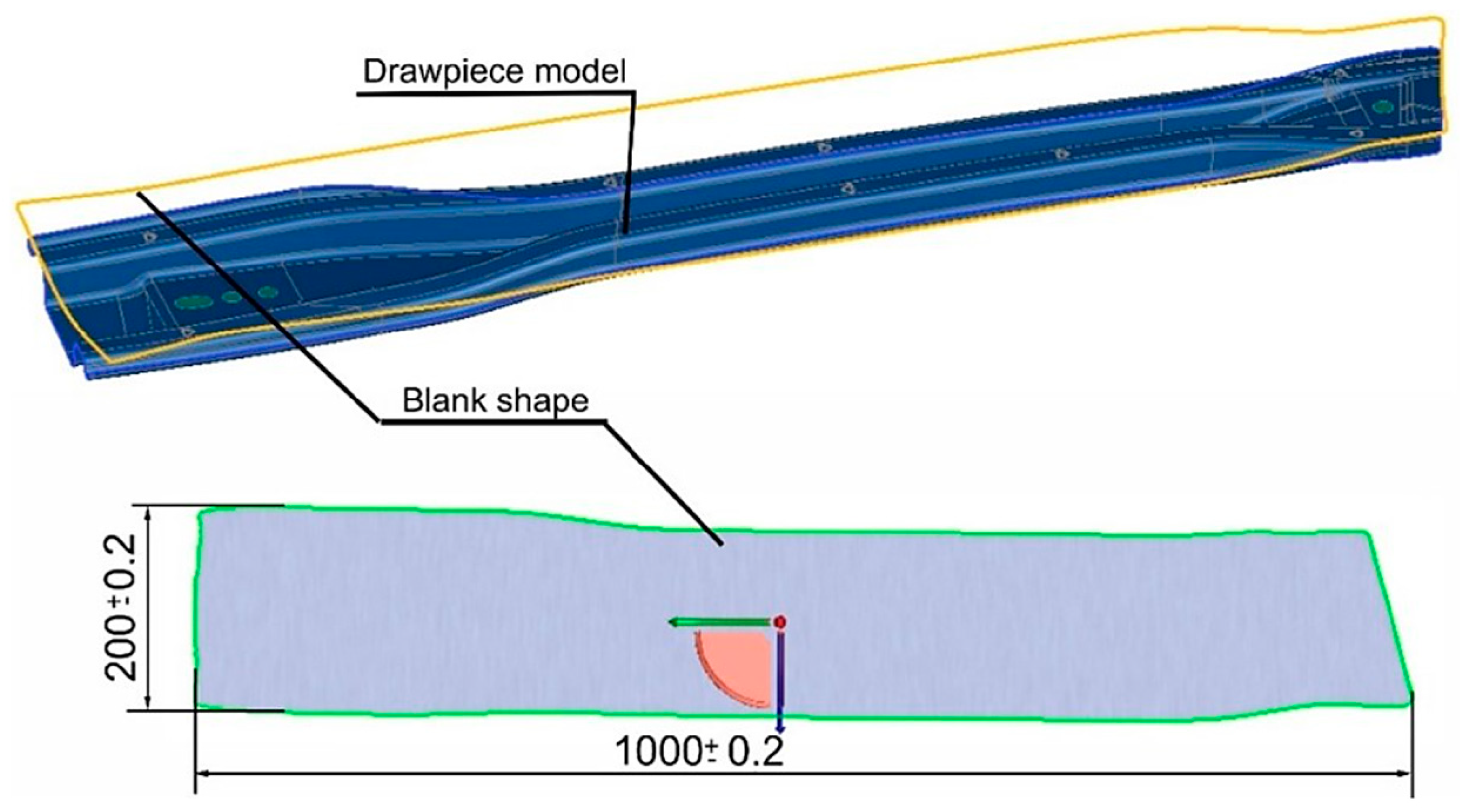
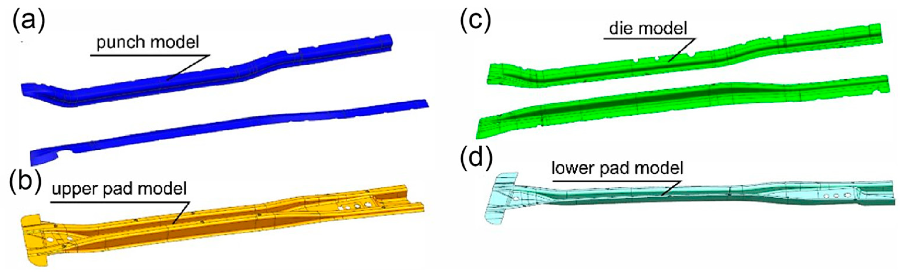
2.1. Design and Simulation

The current study addresses the hot stamping of a front door beam, whose CAD (computer-aided design) model is shown in Figure 2. A front door beam strengthens the door and protects the driver and passengers from the effects of a side impact. It is a double U-shaped beam with a length of 1000 mm and a width of 150 mm. The material used for the investigations was a 1 mm thick sheet of Usibor® 1500P [11] steel produced by ArcelorMittal, which is a type of 22MnB5 steel. The typical chemical composition of 22MnB5 steel is given in Table 1 [12]. The aim of this research was to produce a part with the geometry shown in Figure 2 and a minimum hardness of 400 HV1.
The finite element method (FEM) analysis of the hot stamping process was performed using the Autoform v.10 software system. The first step of the analysis concerned the shape definition of the flat blank with a specific tolerance of the outline (Figure 3). For this purpose, a dedicated Autoform software module was used for the so-called reverse analysis.
For the FEM analysis, CAD models of the surfaces shaping the tools, including the die, punches and clamps, were designed as shown in Figure 4. A commercial CAD software SolidWorks 2016 was used for this purpose.
The blank was meshed with three-node EPS-11 [13] finite elements with an initial size of 10 mm. These are elastic plastic shell elements with 11 points of integration along the thickness. Each node of the element has five degrees of freedom: three translations towards the two tangent vectors and the normal vector, and two rotations with the tangent vectors as the axis of rotation. They are recommended by the manufacturer of the Autoform R10 software for modeling the phenomena that occur during hot stamping. During the stamping analysis, mesh quality adaptation was selected with a control parameter of 3, which allows for each triangular element to be divided into 4 parts. The principle of dividing triangular finite elements into parts according to the value of the refinement level parameter is shown in Figure 5.
The Autoform software uses several parameters to control mesh adaptation. These parameters include: the radius penetration, the max element angle, the refinement for wrinkles, the tangential refinement, the refinement of smooth surfaces and the mapping of state variables during refinement and de-refinement. The parameters are all fully described in [13].
Figure 6 shows the size and shape of the FEM mesh that was applied to the blank before the forming process and hardening (a) and the size and shape of the FEM mesh on the drawpiece after the process (b).
The CAD model of the blank and CAD models of the tools were imported to the Autoform software. The tool elements were positioned appropriately symmetrical to each other to reproduce the real tool. Figure 7 shows a discrete model made to simulate the hot stamping process using a flexible blank and its rigid tools (i.e., the punch, die and upper and lower pads). The material properties of 22MnB5 steel were assigned to the model. The interaction between the working surfaces of the tools and the form was modeled as frictional contact elements with a friction coefficient of 0.45. The position of pilots was also defined, which is responsible for the repeatable and stable position of the form in relation to the tool elements. For the model built in this way, the kinematics of the pressing process was defined as follows: (1) the upper clamp closes the form in the lower clamp, which forms the central part of the beam is formed and (2) the punch moves, closing the die, and forming the edge of the beam. The tools (top and bottom stamp) move at two different speeds. The initial speed is equal to 650 mm/s, and it concerns idle movement (movement of the tool approaching the form). The second speed (the forming speed) is equal to 80 mm/s.
The thermal parameters for the hot stamping process were defined in the following steps. We assumed that the temperature of the blank after removal from the furnace was 920 °C. The blank was transferred from the furnace to the die in 7 s. After the pressing process, the drawpiece was closed in the tool for 8 s, during which the quenching process took place. The initial temperature of the water in the cooling channels was 20 °C. The pressing force of the tools against the form during the hardening process was equal to 1.5 KN. The resultant parametrized model was analyzed in the Autoform thermosolver. A computational model of the hot stamping process is called a digital twin, and it is used to optimize the parameters of the hot stamping process with high accuracy [19,20].

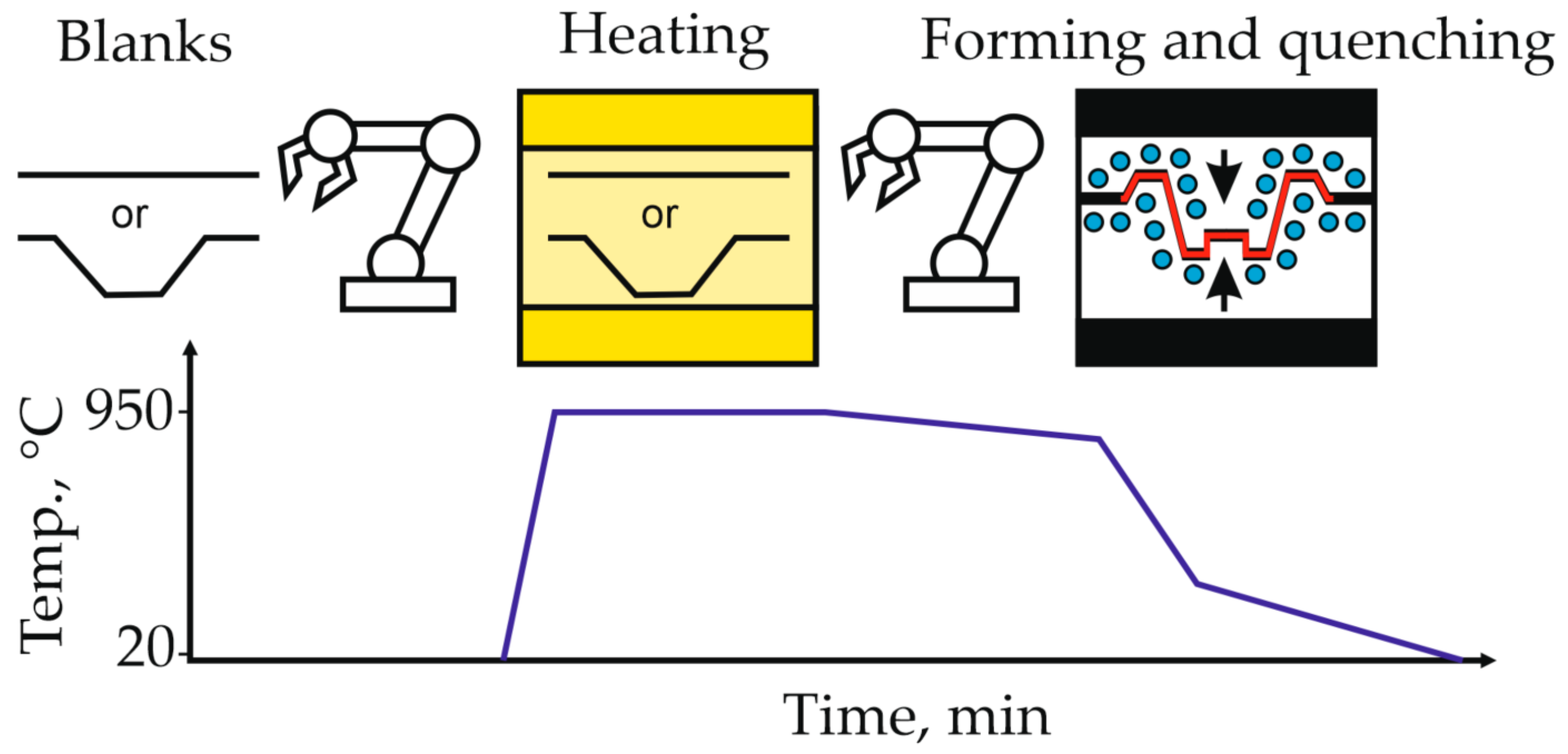
2.2. Experimental Hot Stamping

The simulation results were used in the design and production of the full-size hot-forming tool. Figure 8 compares the CAD model of the upper and lower parts of the tool to photographs of the upper and lower parts of the actual tool that is used to produce a set of door beams. The set of symmetrical door beams includes four beams: two for the front door and two for the rear door.
The previously defined parameters that were used for the simulation were also applied to the part production. A vertical, 3-chamber furnace with a dew point control system of −5 °C was used to heat the blanks. The furnace did not have a protective atmosphere.

2.3. Microstructure and Hardness

The microstructure and properties of the hot stamped element were investigated using light microscopy (using Zeiss AxioObserver, Oberkochen, Germany) and the Vickers hardness test (using a microhardness tester FUTURE-TECH CORP. FB−700, Kawasaki, Japan at a load of 10 N). The test samples were cut from representative areas of the manufactured element. The tests were performed on the sheet cross-section, perpendicular to the longer side of the element. The samples were prepared according to the following standard metallographic procedures: (1) grinding up to 2000 grids, (2) polishing using 3 and 1 µm diamond pastes and (3) etching in nital for ~3 s at room temperature.

3. Results and Discussion

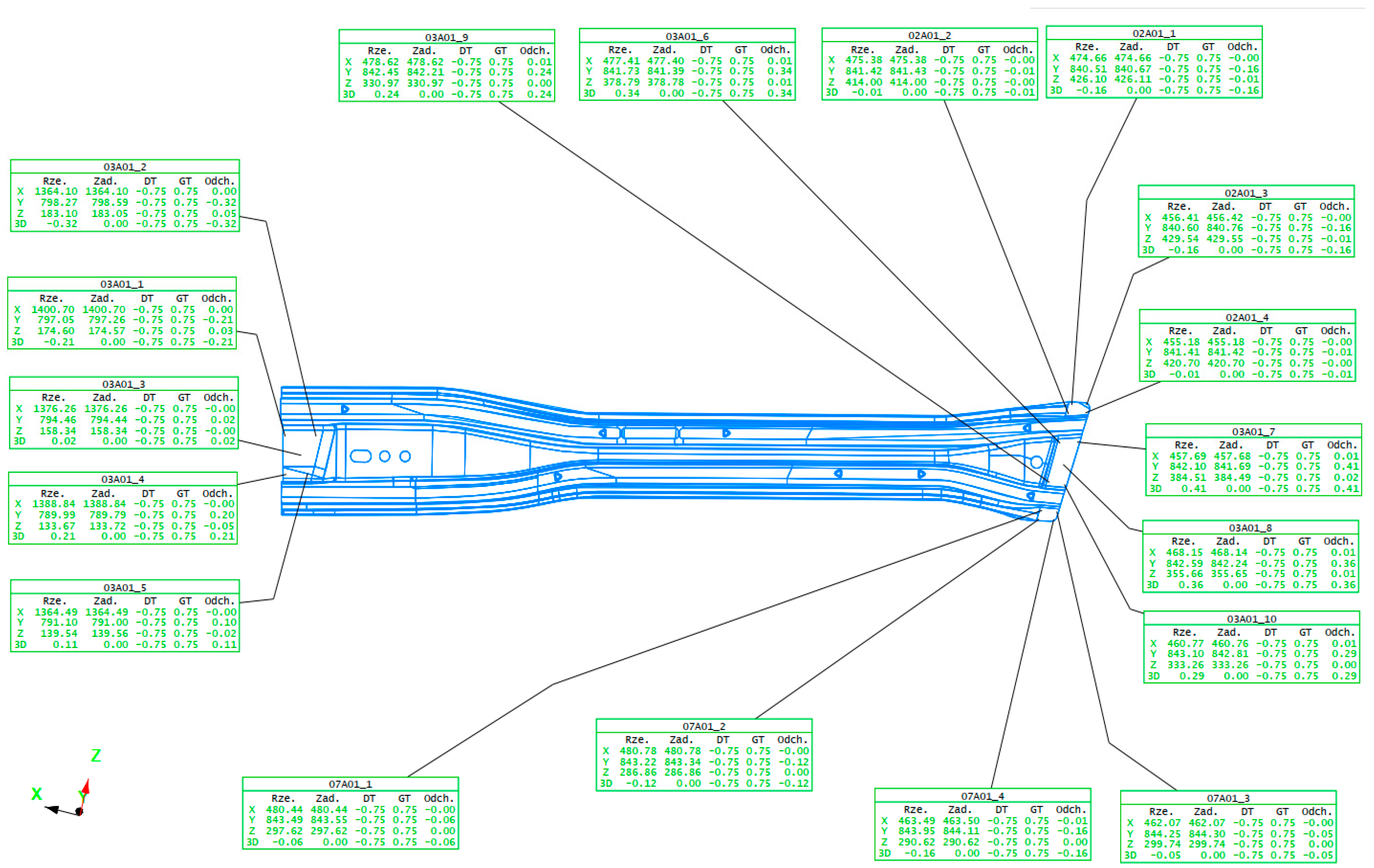
3.1. Results of the Numerical Analysis

The most important results of an FEM analysis of the hot stamping processes, which are analyzed by designers and technologists, include [2,12]:
-
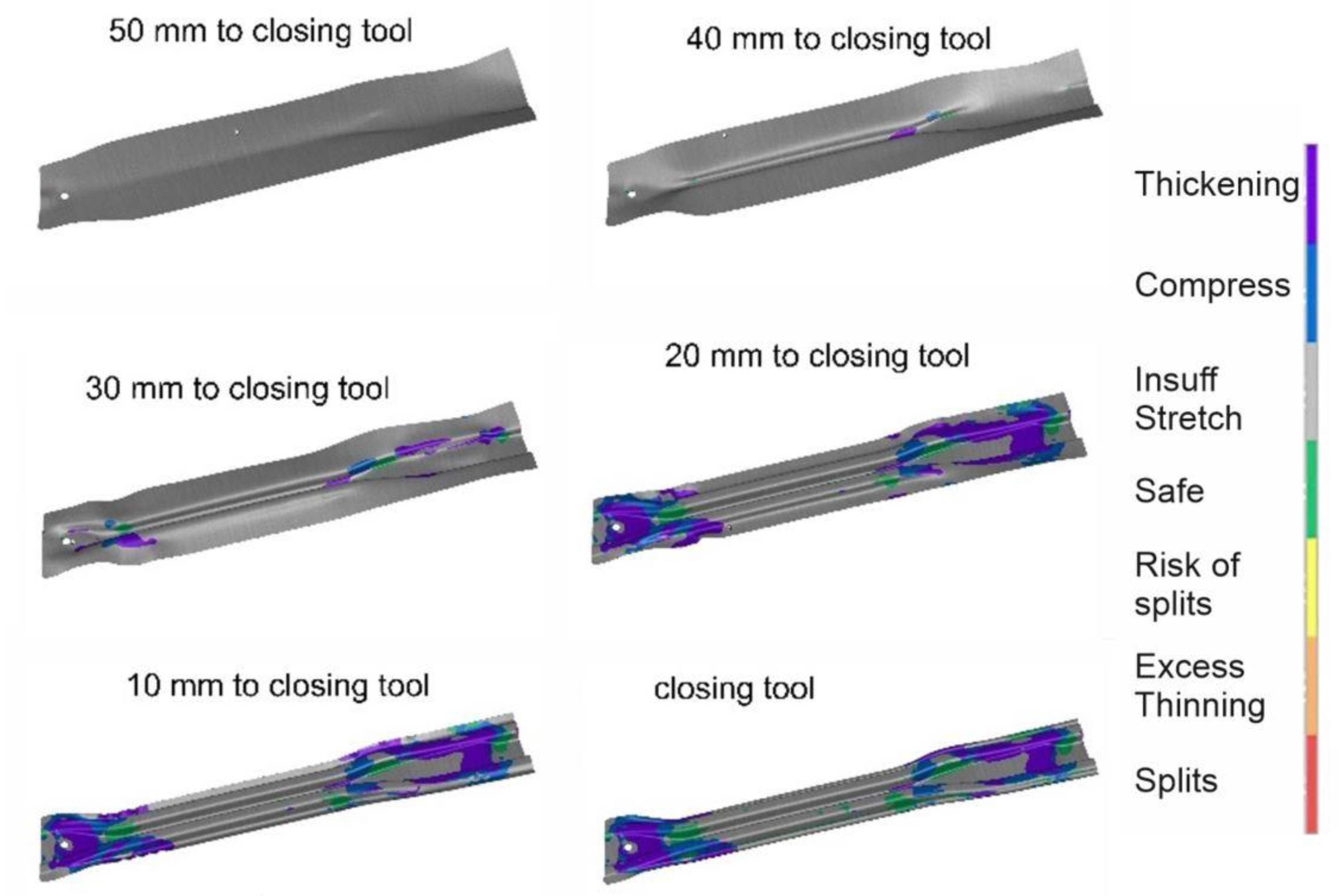
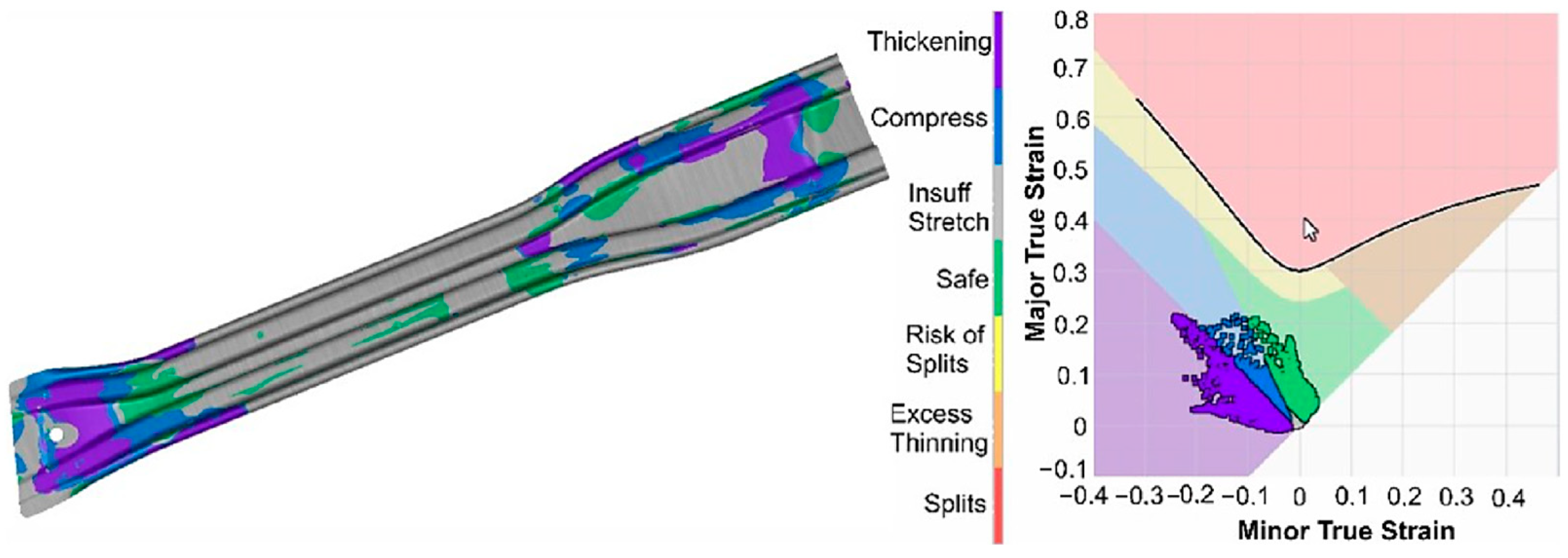
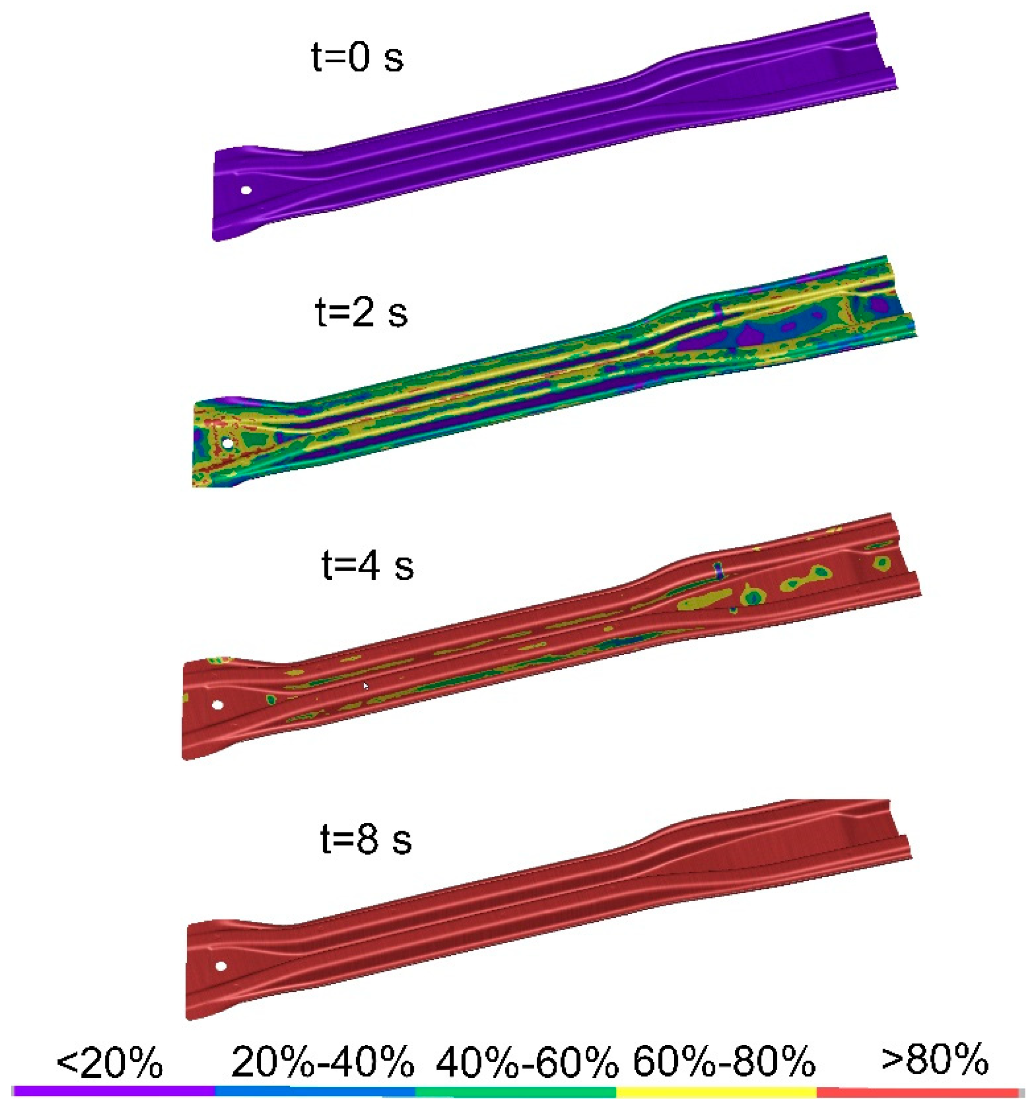
A visualization of the stages of forming as a function of the distance between the die and the punch;
-
A FLD (Forming Limit Diagram) diagram of the drawpiece [7,21];
-
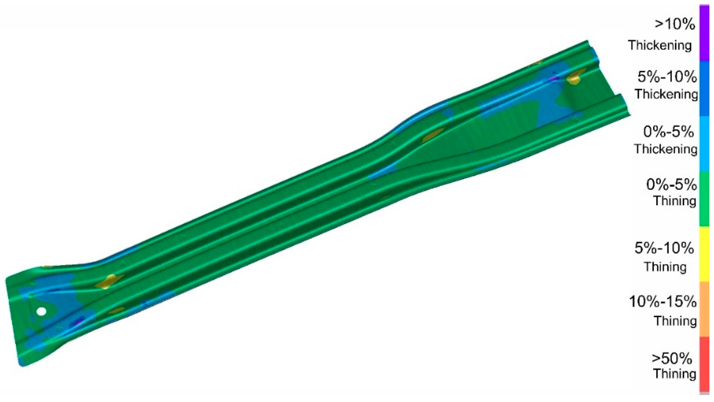
A distribution of thinning for the drawpiece;
-
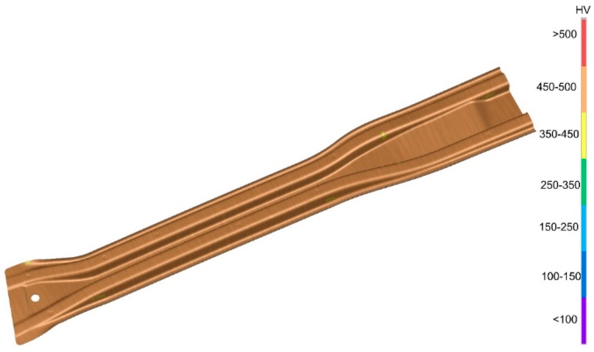
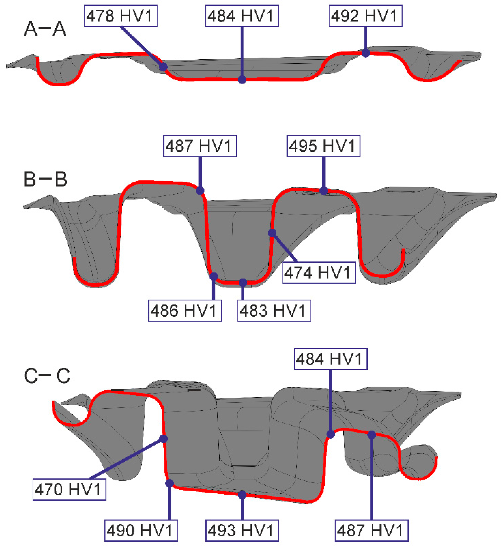
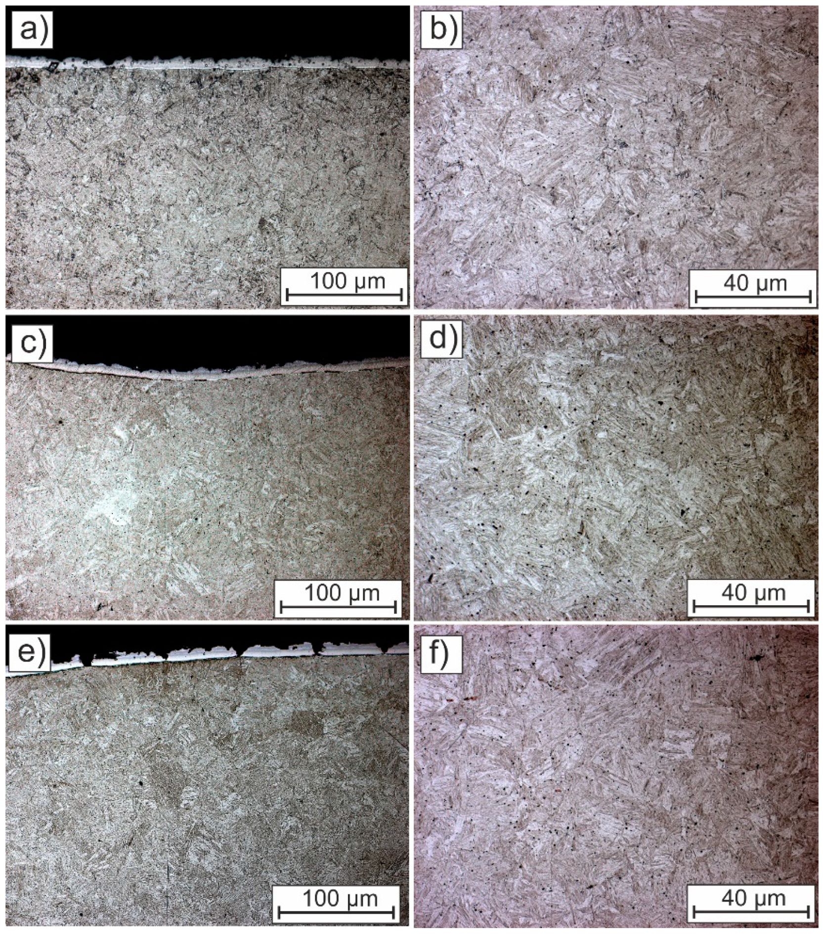
A distribution of the drawpiece hardness and microstructure.
Figure 9 shows the results of the door beam analysis in the form of the FLD diagram visualization at different beam forming stages.
The scale shows the relationship between the minor and major true strain in different areas of the part, which for the fully formed part is shown in Figure 10. The FLD distribution can be used to identify the risk of basic drawpiece defects, i.e., cracks or wrinkles [22]. No regions were observed on the surface of the extrudate that might tend to crack and form wrinkles.
There should be no areas on the drawpieces where the thinning is greater than 10%. The results of the thickness change simulations, presented in Figure 11, identified no regions where the thinning exceeded the limit value.
We also analyzed the simulated hardness of the drawpiece (Figure 12) after the forming and quenching process and its structural changes (Figure 13) during forming and quenching progress. The hardness of the drawpiece after processing should be greater than 400 HV. The simulation results showed that this condition was properly met. Figure 13 shows the results of the quenching in the form of distribution lines of the percentage of martensite in the hot-stamped element during quenching.
Over 99% of martensite was obtained in the structure of the material due to the designed die-cooling system and the hardening properties of the 22MnB5 steel [23]. Quenching occurs first on the bent surfaces of the die and then on the surfaces perpendicular to its axis. The surfaces parallel to the working axis of the die are quenched last.
Figure 14 shows the simulated temperatures of the working surfaces of the upper and lower parts of the tool after 12 cycles. The highest temperature on the working surface of the tool was 115 °C, which did not exceed the maximum value of the assumed working temperature of the tool (200 °C). These results indicated that the properly designed cooling system allows for continuous work of the die in the hot stamping process.
Figure 15 shows the forces acting on the individual elements of the tool that are necessary to form the drawpiece. The simulation results indicated that the proposed parameters of the hot stamping process, including the proposed division of the tool into a punch, a die and stamps, meet the technical and technological requirements. There was no risk of zones with wrinkles and cracks. The drawpiece also achieved the required parameters related to quenching (hardness and microstructure). After 12 operating cycles, the tool reached a constant and safe working temperature. This designed tool was used to produce the beam test series. Figure 16 shows the manufactured beam, which was the subject of the FEM analysis described in this paper. The beam was tested for shape-and-dimensional accuracy. The shape and dimension measurements were obtained using a coordinate measuring machine. Figure 17 shows an example of a measurement card. The assumed accuracy was not exceeded in any of the tested points, and it is in line with the simulation.

3.2. Properties and Microstructure Validation

The microstructure and hardness of the drawpiece were examined to validate the simulation results. The measurements and observations that were taken from representative areas (showing different geometry, cooling rate and thickness) are presented in Figure 18.
Figure 19 shows how the hardness of the part changes depending on the cross-section and its specific area. The average hardness of the part was 486 ± 8 HV1, which significantly exceeds the assumed minimum value. The average hardness for the curved and flat surfaces, which are perpendicular to the operation direction of the tool, showed a similar average hardness of 489 HV. However, the hardness value was slightly lower (472 HV1) for the surfaces parallel to the operation direction of the tool. The simulation results (Figure 13) show that these areas were quenched last. The cooling rate was lower in these areas, which may result in a slightly lower hardness [23].
The micrographs presented in Figure 20 show that all sample areas exhibited fine and homogeneous martensitic microstructure [24]. The only difference was visible in the surface layer (Figure 20a,c,e). The blank was covered by Al–Si anti-corrosive coating [25]. The coating was below 15 μm in thickness and was continuous for the flat (Figure 20a) and concave surfaces (Figure 18C). However, for convex surfaces (Figure 20e), the coating was discontinuous and cracked due to the strong local deformation.

4. Conclusions

This paper presents a comprehensive case study of the design, simulation and experimental evaluation of automotive door beam hot forming. All steps were characterized starting with the beam part CAD model definition and ending with the experimental validation of the hot-stamped part. The main findings confirm that the properly performed process of design and modeling of hot forming technology is crucial for obtaining the desired shape, microstructure and properties of the produced part. The currently available software allows for precise modeling of the given die and punch elements with high accuracy, which is required to obtain the desired properties of the produced autobody part. This process design and methodology reduces the implementation time to produce a new part and significantly decreases the costs that arise due to an incorrectly produced tool or its experimental validation. The critical points in the design of the performed hot stamping process were: a proper design of the tool that ensured major–minor true strain at the safety level, which prevents cracking and the formation of wrinkles; a sufficient cooling rate that produced the fully martensitic microstructure; and an effective water-cooling system that maintained the working temperature of the die at a low level (~115 °C) that was beneficial in terms of the continuous long-term tool usage.
This research shows that the assumed initial requirements, such as shape, microstructure or hardness of the hot-formed element, were fully met when using the parameters developed through the simulation and numerical analysis. A beneficial homogeneous martensite microstructure (100%) exhibiting hardness higher than the required 400 HV1 (486 ± 8 HV1) was obtained in a complex-shaped autobody part. The quenching occurred first in regions that were formed in the initial step of closing the tool, which resulted in the highest hardness. The lowest hardness was obtained on surfaces that were parallel to the direction of the tool because these areas had the lowest cooling rate. Therefore, quenching is a sensitive point in the process that affects the quality of the product produced. This investigation also showed that bending of the steel sheet leads to cracking of the surface layer in convex surfaces.

Author Contributions

Conceptualization, I.W. and A.S.; methodology, I.W. and A.G.; software, I.W.; validation, I.W. and A.G.; formal analysis, A.S.; investigation, I.W.; resources, A.G.; data curation, I.W. and A.S.; writing—original draft preparation, I.W., A.S. and A.G.; writing—review and editing, A.G.; visualization, I.W.; supervision, A.G.; project administration, I.W. and A.G.; funding acquisition, A.G. All authors have read and agreed to the published version of the manuscript.

Funding

This research was supported by statutory funds of the Faculty of Mechanical Engineering, Silesian University of Technology in 2022.

Data Availability Statement

Not applicable.

Acknowledgments

A. Skowronek acknowledges financial support through the 10/010/BKM22 project, Faculty of Mechanical Engineering, Silesian University of Technology, Gliwice, Poland.

Conflicts of Interest

The authors declare no conflict of interest.

References

  1. Billur, E. Hot Stamping of Ultra High-Strength Steels; Springer: New York, NY, USA, 2018; ISBN 978-3-319-98868-9. [Google Scholar]
  2. Karbasian, H.; Tekkaya, A.E. A Review on Hot Stamping. Mater. Process. Technol. 2010, 210, 2103–2118. [Google Scholar] [CrossRef]
  3. Neugebauer, R.; Schieck, F.; Polster, S.; Mosel, A.; Rautenstrauch, A.; Schönherr, J.; Pierschel, N. Press Hardening—An Innovative and Challenging Technology. Archiv. Civ. Mech. Eng. 2012, 12, 113–118. [Google Scholar] [CrossRef]
  4. Grajcar, A.; Skrzypczyk, P.; Wozniak, D. Thermomechanically Rolled Medium-Mn Steels Containing Retained Austenite. Arch. Metall. Mater. 2014, 59, 1691–1697. [Google Scholar] [CrossRef]
  5. Huang, F.; Chen, Q.; Ding, H.; Wang, Y.; Mou, X.; Chen, J. Automotive Steel with a High Product of Strength and Elongation Used for Cold and Hot Forming Simultaneously. Materials 2021, 14, 1121. [Google Scholar] [CrossRef]
  6. Derazkola, H.A.; García Gil, E.; Murillo-Marrodán, A.; Méresse, D. Review on Dynamic Recrystallization of Martensitic Stainless Steels during Hot Deformation: Part I—Experimental Study. Metals 2021, 11, 572. [Google Scholar] [CrossRef]
  7. Li, H.; Wu, X.; Li, G. Prediction of Forming Limit Diagrams for 22MnB5 in Hot Stamping Process. Mater. Eng. Perform. 2013, 22, 2131–2140. [Google Scholar] [CrossRef]
  8. Liu, S.; Long, M.; Zhang, S.; Zhao, Y.; Zhao, J.; Feng, Y.; Chen, D.; Ma, M. Study on the Prediction of Tensile Strength and Phase Transition for Ultra-High Strength Hot Stamping Steel. Mater. Res. Technol. 2020, 9, 14244–14253. [Google Scholar] [CrossRef]
  9. Caia, Y.; Halim, F.; Li, G.; Chen, S. Hot Stamping Simulation and Austenite Decomposition Modeling of an Automobile Cross Member. Procedia Eng. 2011, 15, 4902–4907. [Google Scholar] [CrossRef] [Green Version]
  10. Xu, L.; Chen, L.; Chen, G.; Wang, M. Hot Deformation Behavior and Microstructure Analysis of 25Cr3Mo3NiNb Steel during Hot Compression Tests. Vacuum 2018, 147, 8–17. [Google Scholar] [CrossRef]
  11. Hein, P.; Wilsius, J. Status and Innovation Trends in Hot Stamping of USIBOR 1500 P. Steel Res. Int. 2008, 79, 85–91. [Google Scholar] [CrossRef]
  12. Wróbel, I.; Skowronek, A.; Grajcar, A. A Review on Hot Stamping of Advanced High-Strength Steels: Technological-Metallurgical Aspects and Numerical Simulation. Symmetry 2022, 14, 969. [Google Scholar] [CrossRef]
  13. Autoform Help System. Available online: https://servicecenter.autoform.com (accessed on 1 November 2022).
  14. Trzepiecinski, T.; Lemu, H.G. Recent Developments and Trends in the Friction Testing for Conventional Sheet Metal Forming and Incremental Sheet Forming. Metals 2020, 10, 47. [Google Scholar] [CrossRef] [Green Version]
  15. Sajan, M.; Amirthalingam, M.; Chakkingal, U. A Novel Method for the Spring-Back Analysis of a Hot Stamping Steel. Mater. Res. Technol. 2021, 11, 227–234. [Google Scholar] [CrossRef]
  16. Aydin, H.; Essadiqi, E.; Jung, I.-H.; Yue, S. Development of 3rd Generation AHSS with Medium Mn Content Alloying Compositions. Mater. Sci. Eng. A 2013, 564, 501–508. [Google Scholar] [CrossRef]
  17. Dharavath, B.; Morchhale, A.; Singh, S.K.; Kotkunde, N.; Naik, M.T. Experimental Determination and Theoretical Prediction of Limiting Strains for ASS 316L at Hot Forming Conditions. Mater. Eng. Perform. 2020, 29, 4766–4778. [Google Scholar] [CrossRef]
  18. Li, S.; Luo, H. Medium-Mn Steels for Hot Forming Application in the Automotive Industry. Int. J. Miner. Metall. Mater 2021, 28, 741–753. [Google Scholar] [CrossRef]
  19. Zambrano, V.; Mueller-Roemer, J.; Sandberg, M.; Talasila, P.; Zanin, D.; Larsen, P.G.; Loeschner, E.; Thronicke, W.; Pietraroia, D.; Landolfi, G.; et al. Industrial Digitalization in the Industry 4.0 Era: Classification, Reuse and Authoring of Digital Models on Digital Twin Platforms. Array 2022, 14, 100176. [Google Scholar] [CrossRef]
  20. Yanagimoto, J.; Banabic, D.; Banu, M.; Madej, Ł. Simulation of Metal Forming—Visualization of Invisible Phenomena in the Digital Era. CIRP Ann. 2022, 71, 599–622. [Google Scholar] [CrossRef]
  21. Lin, J.; Mohamed, M.; Balint, D.; Dean, T. The Development of Continuum Damage Mechanics-Based Theories for Predicting Forming Limit Diagrams for Hot Stamping Applications. Int. J. Damage Mech. 2014, 23, 684–701. [Google Scholar] [CrossRef]
  22. Cui, J.; Sun, G.; Xu, J.; Huang, X.; Li, G. A Method to Evaluate the Formability of High-Strength Steel in Hot Stamping. Mater. Des. 2015, 77, 95–109. [Google Scholar] [CrossRef]
  23. Çavuşoğlu, O.; Çavuşoğlu, O.; Yılmazoğlu, A.G.; Üzel, U.; Aydın, H.; Güral, A. Microstructural Features and Mechanical Properties of 22MnB5 Hot Stamping Steel in Different Heat Treatment Conditions. Mater. Res. Technol. 2020, 9, 10901–10908. [Google Scholar] [CrossRef]
  24. Venturato, G.; Novella, M.; Bruschi, S.; Ghiotti, A.; Shivpuri, R. Effects of Phase Transformation in Hot Stamping of 22MnB5 High Strength Steel. Procedia Eng. 2017, 183, 316–321. [Google Scholar] [CrossRef]
  25. Klassen, C.M.; Smith, R.D.L.; Daun, K.J. Characterizing the AlSi Coating on 22MnB5 Steel Using Raman Spectroscopy. Mater. Charact. 2022, 189, 112002. [Google Scholar] [CrossRef]
Figure 1. Schematic of the hot stamping process with the temperature profile.
Symmetry 14 02625 g001
Figure 2. Door beam CAD model.
Symmetry 14 02625 g002
Figure 3. Final part and the shape of a flat blank.
Symmetry 14 02625 g003
Figure 4. CAD models of the tools: (a) punch, (b) upper pad, (c) die and (d) lower pad.
Symmetry 14 02625 g004
Figure 5. The principle of dividing finite elements depending on a value of the refinement level parameter.
Symmetry 14 02625 g005
Figure 6. Size and shape of the FEM mesh that was applied to the blank (a) and on the drawpiece (b).
Symmetry 14 02625 g006
Figure 7. A discrete model of the blank and assembled tool with the cooling channels.
Symmetry 14 02625 g007
Figure 8. CAD model of the top and bottom of the tool and photographs of the top and bottom of the actual beam fabrication die.
Symmetry 14 02625 g008
Figure 9. FLD distribution at different forming stages of a drawpiece.
Symmetry 14 02625 g009
Figure 10. Distribution of the risk of cracking and the formation of wrinkles (Forming Limit Diagram).
Symmetry 14 02625 g010
Figure 11. Beam thinning distribution.
Symmetry 14 02625 g011
Figure 12. HV hardness distribution for a formed and quenched beam.
Symmetry 14 02625 g012
Figure 13. Distribution of the percentage of martensite in the drawpiece during quenching.
Symmetry 14 02625 g013
Figure 14. Temperatures of the upper and lower parts of the tool (die).
Symmetry 14 02625 g014
Figure 15. Forces acting on tool components.
Symmetry 14 02625 g015
Figure 16. Manufactured door beam.
Symmetry 14 02625 g016
Figure 17. An example of a measurement card.
Symmetry 14 02625 g017
Figure 18. Element cross-sections in which microstructure and hardness tests were carried out.
Symmetry 14 02625 g018
Figure 19. Hardness in different areas of the part.
Symmetry 14 02625 g019
Figure 20. Microstructures in different areas of the sample (a,b) flat-horizontal surface, (ce) curved surface, (f) flat-vertical surface.
Symmetry 14 02625 g020
Table 1. Typical composition of 22MnB5 steel [12].
Chemical ElementCMnBCrSiAlTiN
wt. %0.19–0.221.10–1.400.0008–0.00500.10–0.35Max 0.40Max 0.08Max 0.045Max
0.01
Publisher’s Note: MDPI stays neutral with regard to jurisdictional claims in published maps and institutional affiliations.

