
Stability Assessment of Tunnels Excavated in Loess with the Presence of Groundwater—A Case Study

Abstract
:1. Introduction
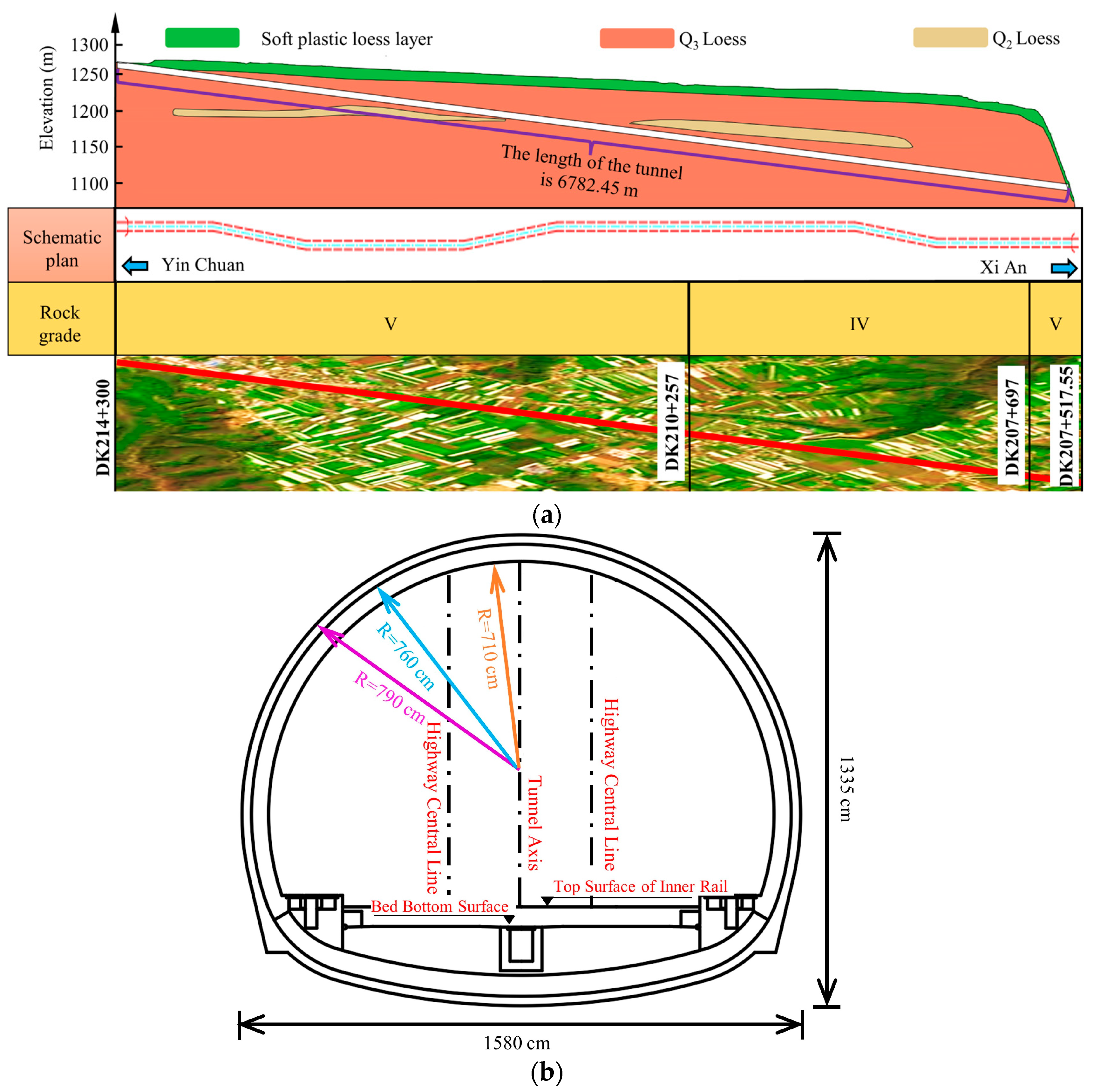
2. Project Overview
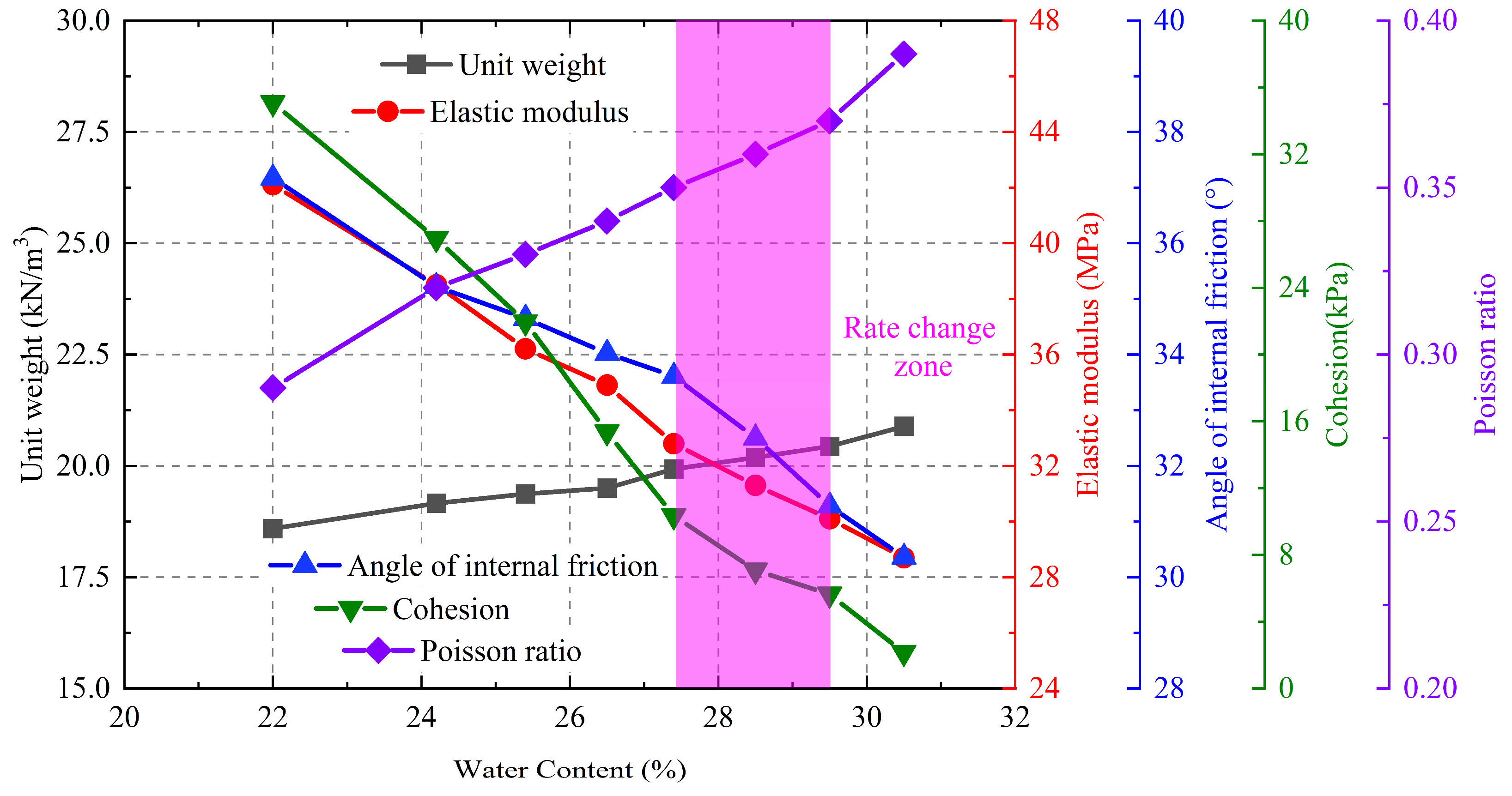
3. Physical and Mechanical Properties of Loess
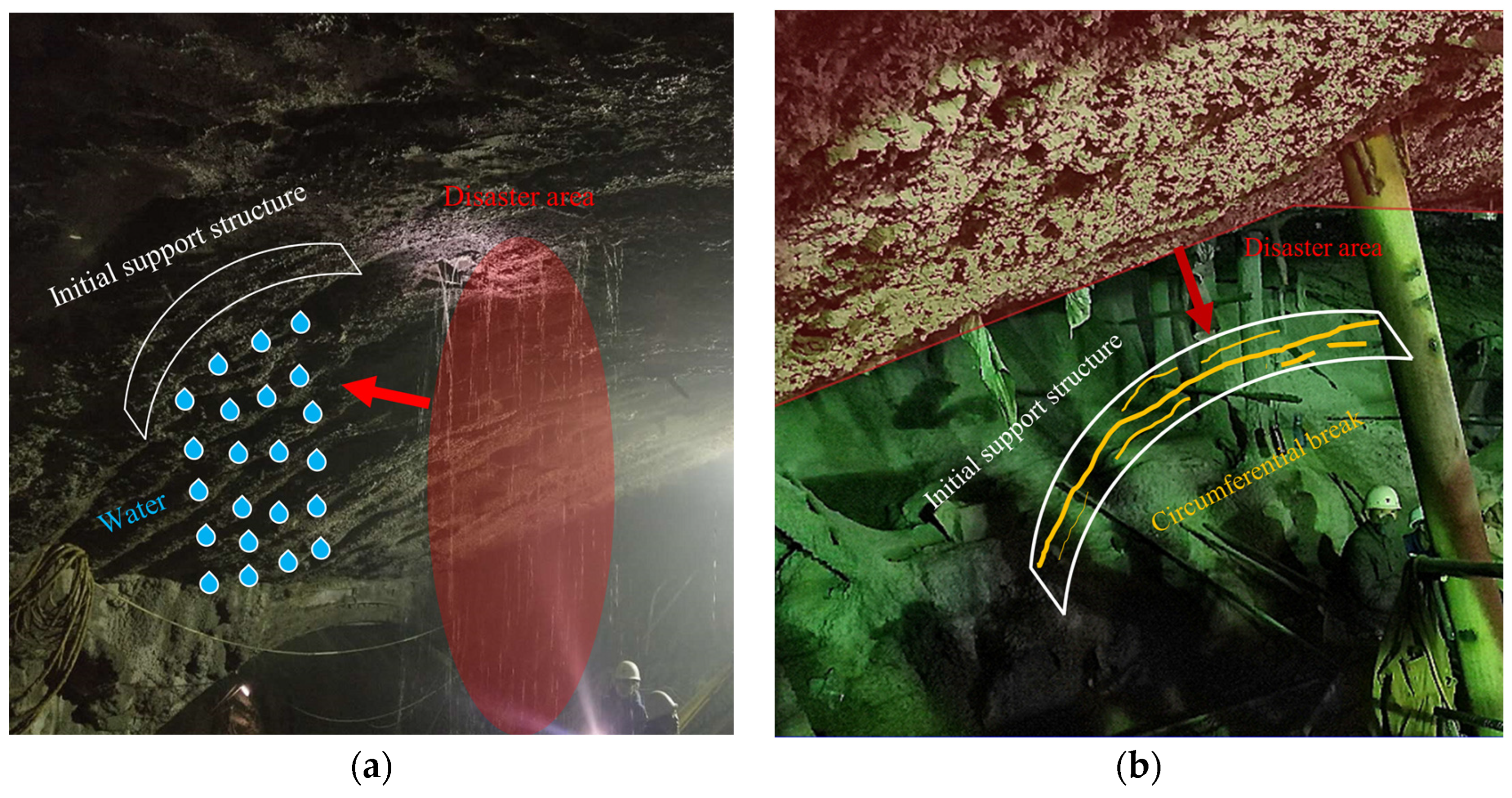
4. Analysis of Deformation Mechanism of Primary Support Structure
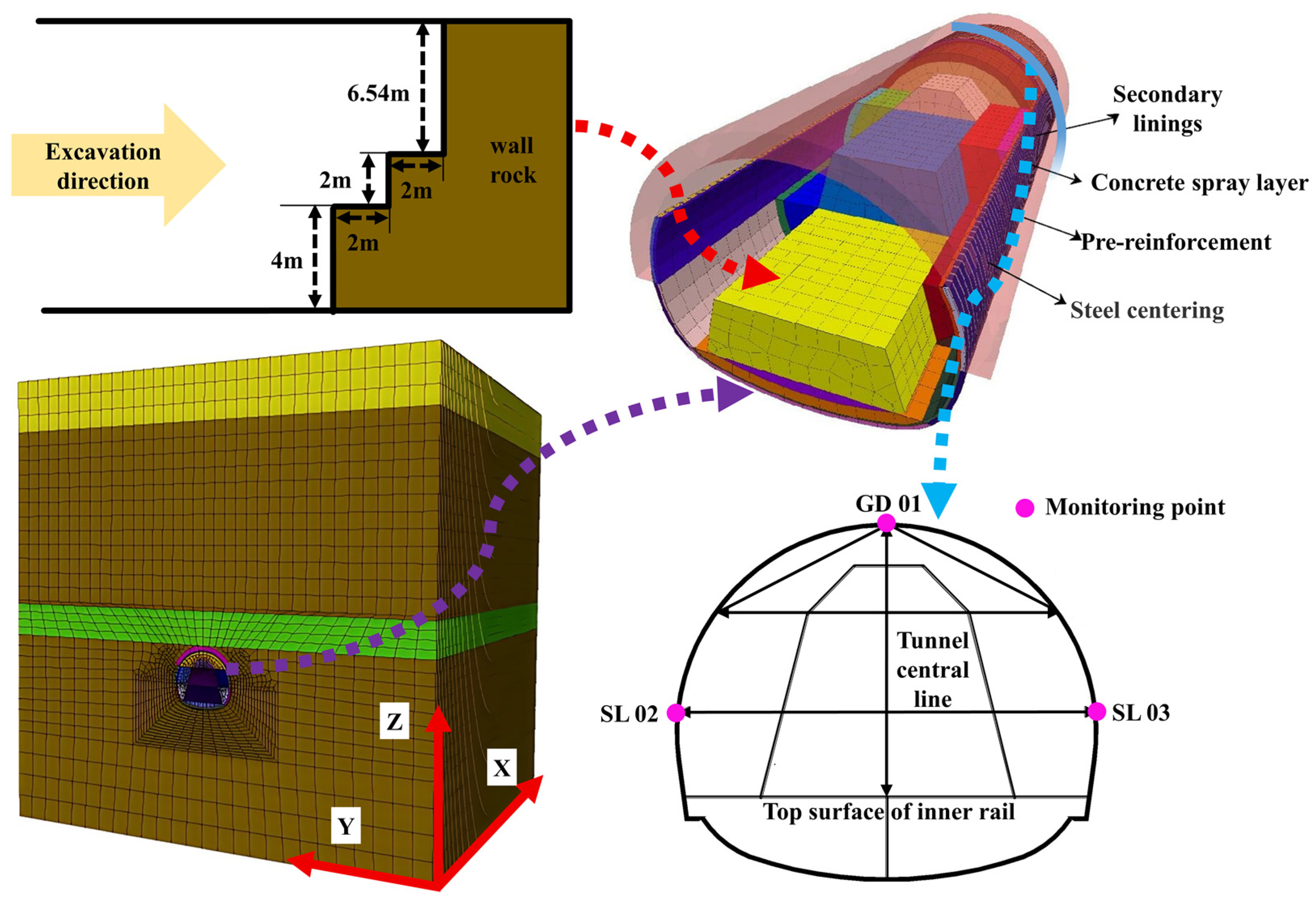
4.1. Numerical Model
4.2. Results
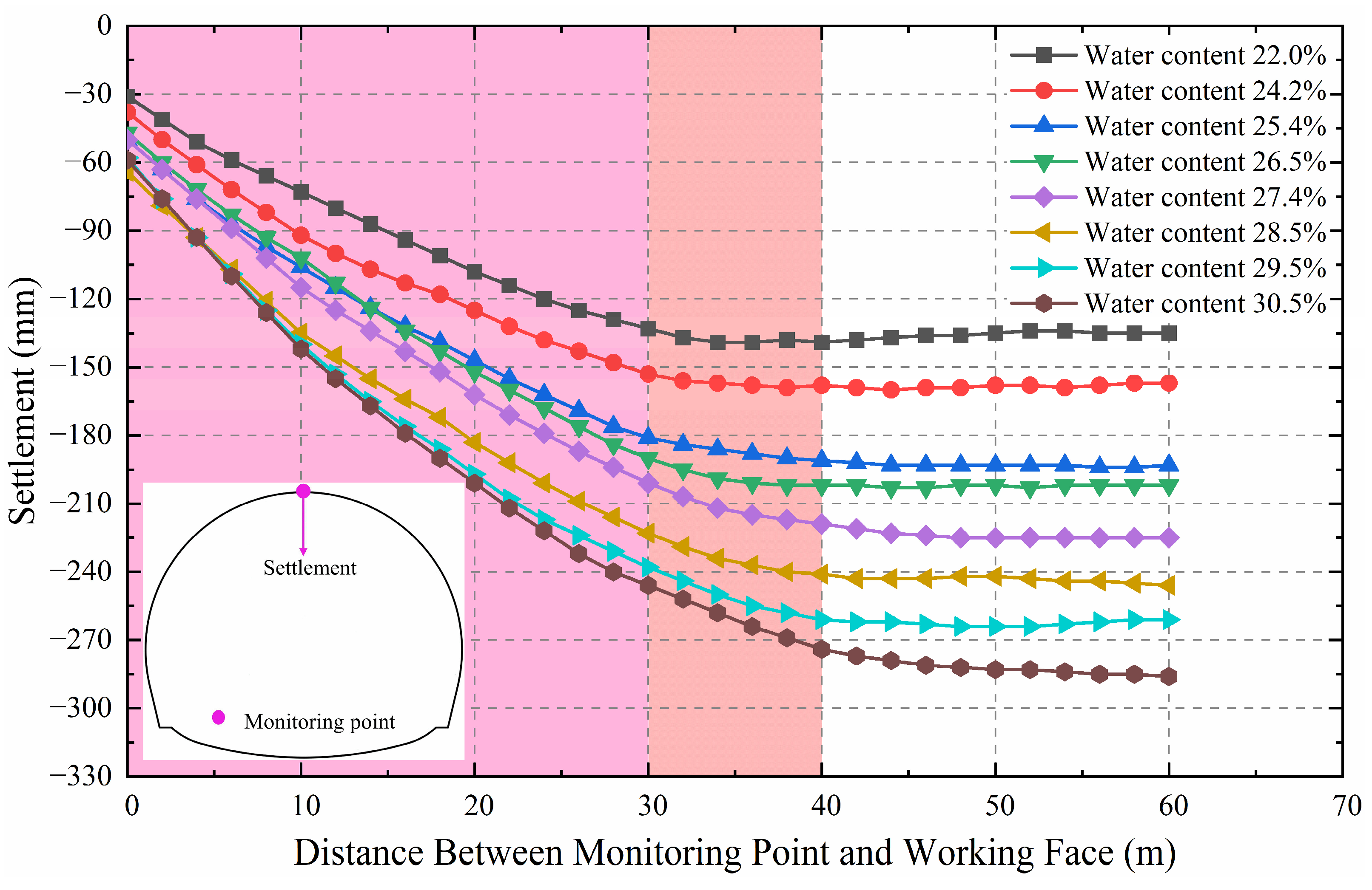
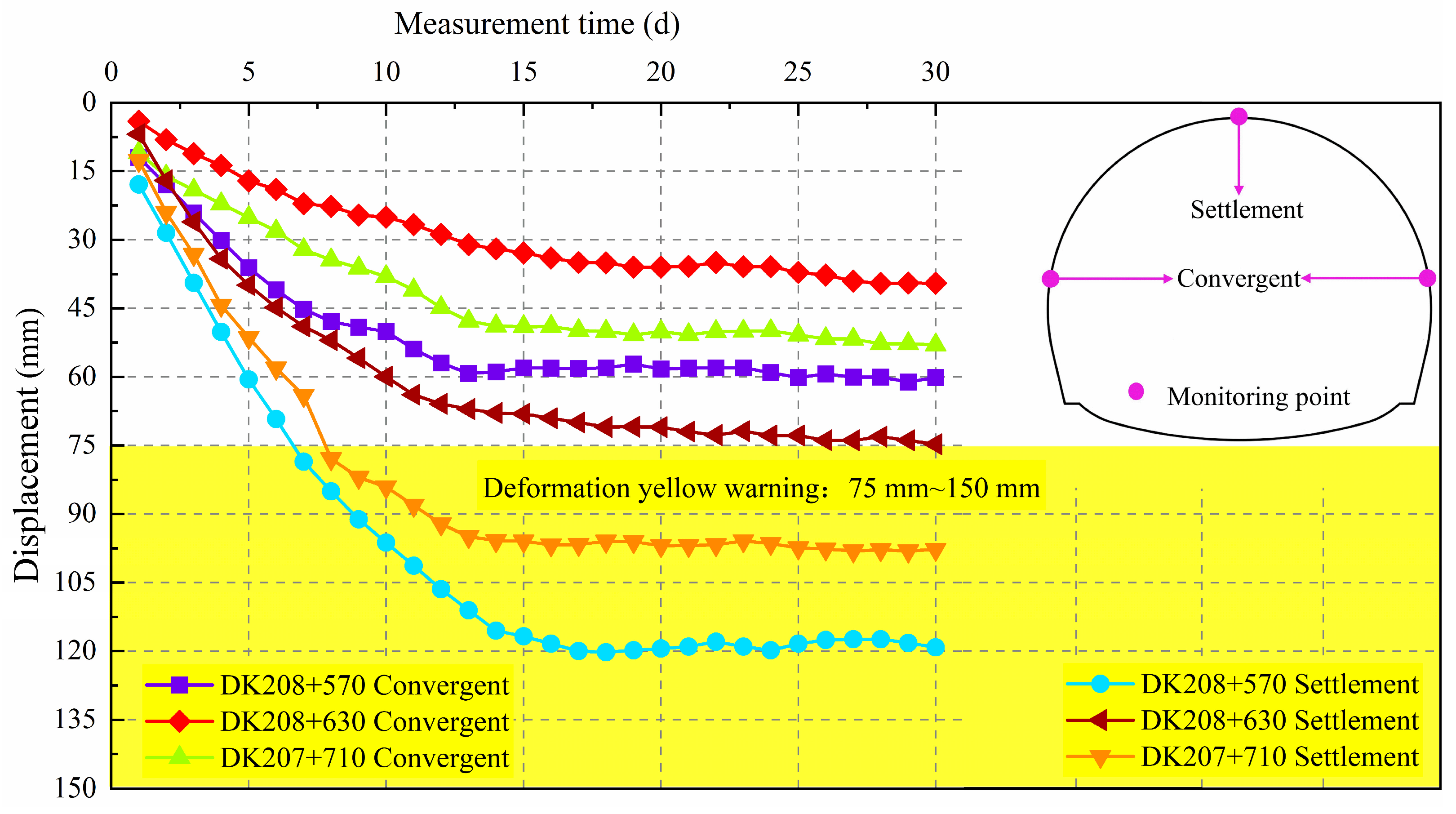
4.2.1. Settlement
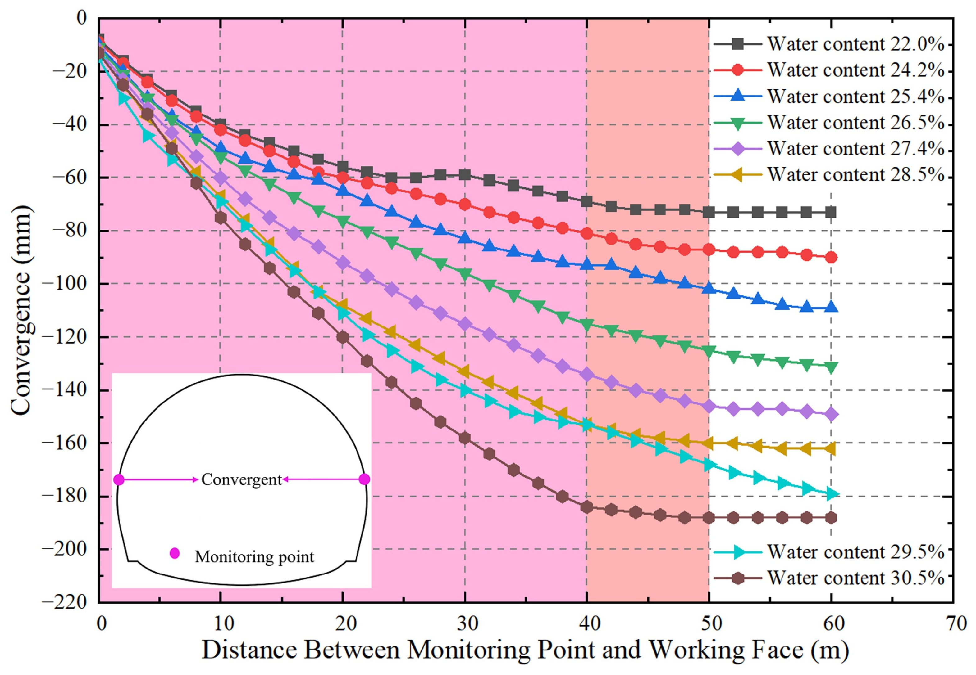
4.2.2. Convergence
4.3. Discussion
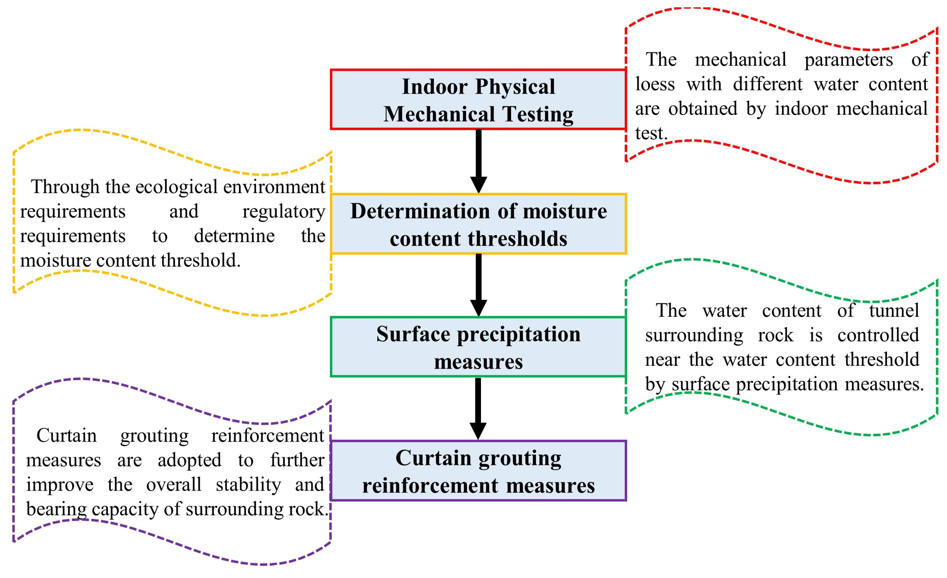
5. Treatment Measure
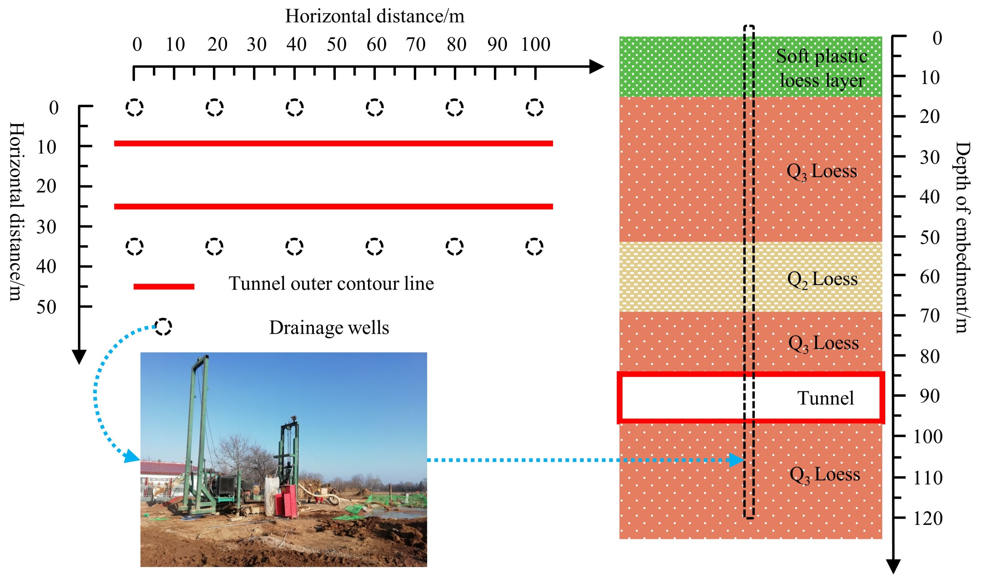
5.1. Surface Precipitation
5.1.1. Design Scheme
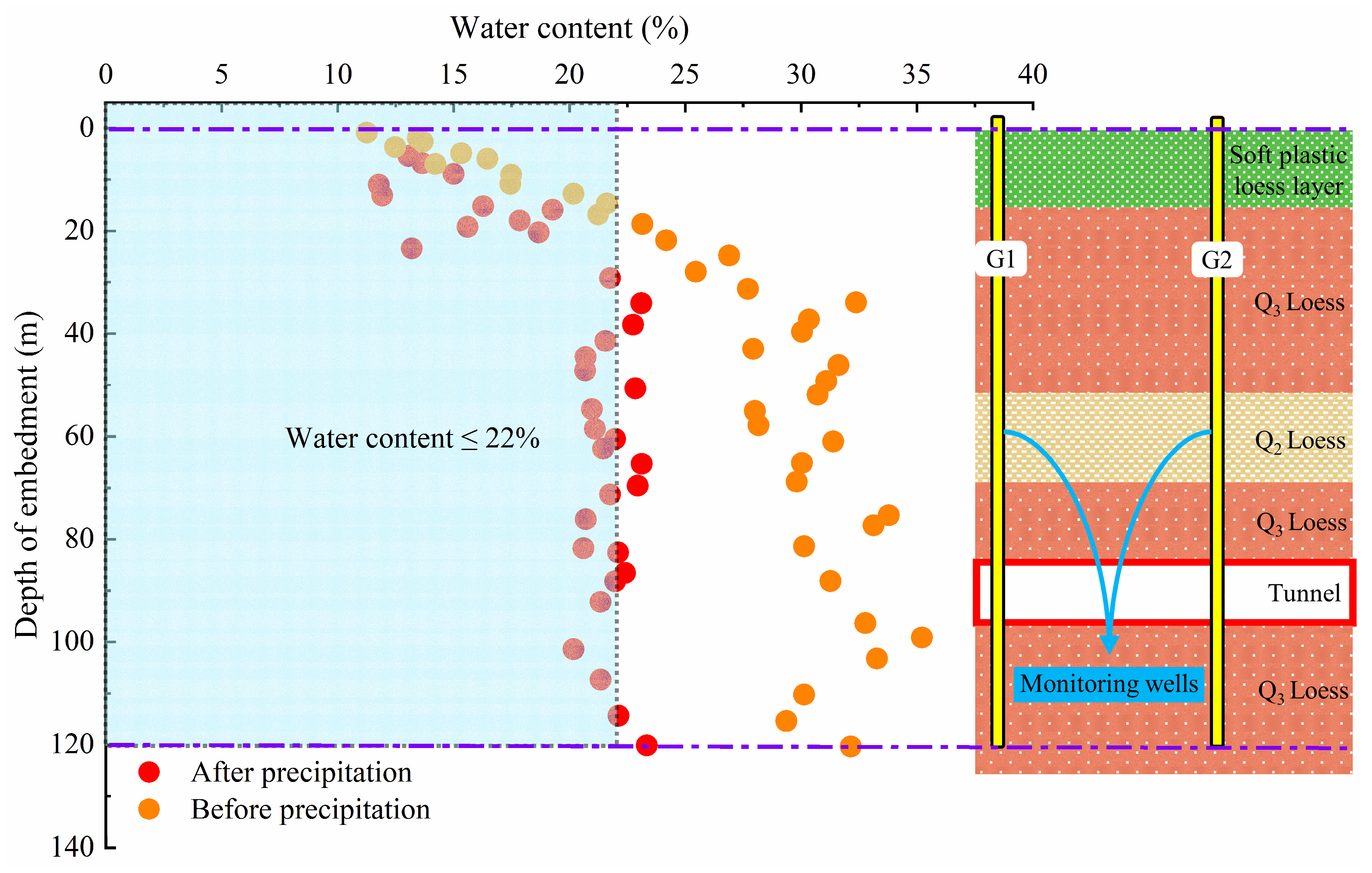
5.1.2. Results and Analyses
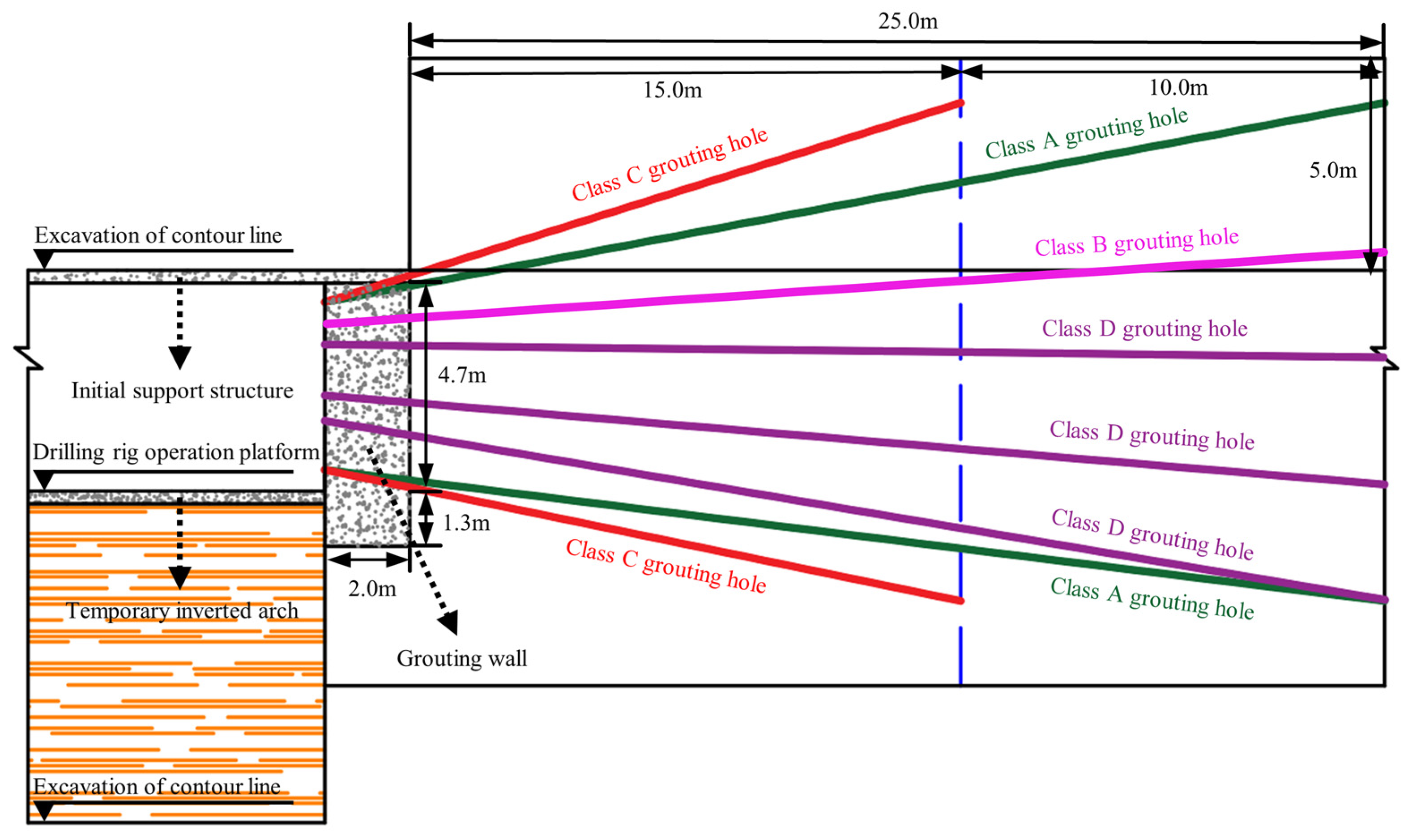
5.2. Curtain Grouting
5.2.1. Design Scheme
5.2.2. Results and Analyses
6. Discussion
7. Conclusions
- (1)
- As the water content of loess increases, water molecules will form a lubricating layer between loess particles, reducing the contact area and internal friction angle between particles. At the same time, after absorbing water, loess will expand, causing the voids in the soil to become larger and the interaction forces between particles to decrease. Therefore, during the construction process of loess tunnels, the water content of the surrounding rock increases, which reduces the cohesion, internal friction angle, and elastic modulus of the surrounding rock, leading to the deterioration of the strength of the surrounding rock, making it more sensitive to subsequent excavation disturbances, and ultimately causing damage to the initial support structure.
- (2)
- As the water content of the loess surrounding rock increases, the settlement of the vault and the convergence of the sidewalls of the surrounding rock show an increasing trend. In addition, the settlement of the vault undergoes three stages: rapid growth, slow growth, and stable stability within the range of 0~30 m, 30~40 m, and 40~60 m from the monitoring section to the palm surface, respectively. The convergence of the sidewalls occurs within the range of 0~40 m, 40~50 m, and 50~60 m from the monitoring section to the palm surface, exhibiting rapid growth, slow growth, and stable stages, respectively. It is worth noting that compared to the vault settlement of the surrounding rock, the convergence of the sidewalls has a significant lag.
- (3)
- Based on the deformation mechanism of the initial support structure of the Shangge Village Tunnel and the requirements of the ecological environment, a water content threshold of 22% is set for the surrounding rock. Based on this threshold, a rock reinforcement scheme combining surface precipitation and curtain grouting is adopted. By taking these measures, the settlement of the vault and the convergence of the sidewalls are both lower than the yellow warning deformation value. Compared with unreinforced and single-curtain grouting measures, the settlement of the vault decreased by 37.29% and 23.81% respectively, and the convergence of the sidewalls decreased by 34.26% and 25.1%, respectively. This indicates that adopting a combination of surface precipitation and curtain grouting for surrounding rock reinforcement has a significant effect on reducing the settlement of the vault and the convergence of the sidewalls.
- (4)
- The reinforcement scheme for loess tunnels based on the water content threshold is analyzed through on-site monitoring data, which prove that this reinforcement scheme can effectively reduce vault settlement and sidewall convergence, ensuring the safety of tunnel construction and operation periods. Therefore, similar studies in the future can further propose more systematic methods to determine more accurate water content thresholds from the aspects of construction convenience and the engineering economy based on this study and try different reinforcement measures to provide more scientific technical support for the construction and operation of loess tunnels.
Author Contributions
Funding
Data Availability Statement
Conflicts of Interest
References
- Xu, Z.; Cai, N.; Li, X.; Xian, M.; Dong, T. Risk Assessment of Loess Tunnel Collapse during Construction Based on an Attribute Recognition Model. Bull. Eng. Geol. Environ. 2021, 80, 6205–6220. [Google Scholar] [CrossRef]
- Fu, J.; Li, H.; Zhu, K.; Chen, Y.; Lei, Z. Study on Expansion Characteristics and Expansion Potential of Gypsum Rock. Geofluids 2022, 2022, 6921150. [Google Scholar] [CrossRef]
- Li, H.; Fu, J.; Chen, B.; Zhang, X.; Zhang, Z.; Lang, L. Mechanical Properties of GFRP Bolts and Its Application in Tunnel Face Reinforcement. Materials 2023, 16, 2193. [Google Scholar] [CrossRef]
- Sharifzadeh, M.; Daraei, R.; Broojerdi, M.S. Design of Sequential Excavation Tunneling in Weak Rocks through Findings Obtained from Displacements Based Back Analysis. Tunn. Undergr. Space Technol. 2012, 28, 10–17. [Google Scholar] [CrossRef]
- Daraei, A.; Zare, S. A New Multi-Graph Approach for Selecting the Sequential Excavation Method of Civil Tunnels. Tunn. Undergr. Space Technol. 2019, 91, 102999. [Google Scholar] [CrossRef]
- Wang, M.; Dong, Y.; Yu, L. Analytical Solution for a Loess Tunnel Based on a Bilinear Strength Criterion. Soil. Mech. Found. Eng. 2020, 57, 296–304. [Google Scholar] [CrossRef]
- Yates, K.; Fenton, C.H.; Bell, D.H. A Review of the Geotechnical Characteristics of Loess and Loess-Derived Soils from Canterbury, South Island, New Zealand. Eng. Geol. 2018, 236, 11–21. [Google Scholar] [CrossRef]
- Yusoff, I.N.; Mohamad Ismail, M.A.; Tobe, H.; Miyoshi, T.; Date, K.; Yokota, Y. Discontinuity Pattern Detection and Orientation Measurement for Tunnel Faces by Using Structure from Motion Photogrammetry. Displays 2023, 76, 102356. [Google Scholar] [CrossRef]
- Ali, A.; Achyuthan, H. Paleoenvironment Shifts during MIS 3: Loess and Loess Paleosols of Kashmir Valley, India. J. Earth Syst. Sci. 2020, 129, 177. [Google Scholar] [CrossRef]
- Goossens, D. Scale Model Simulations of the Deposition of Loess in Hilly Terrain. Earth Surf. Processes Landf. 1988, 13, 533–544. [Google Scholar] [CrossRef]
- Hong, Q.; Lai, H.; Liu, Y.; Chen, R. Distress Mechanism and Treatment Measures in Construction of Large Cross-Section Tunnel Passing through Q2 Soft-Plastic Loess Layer. Bull. Eng. Geol. Environ. 2023, 82, 165. [Google Scholar] [CrossRef]
- Wu, J.; Jiang, J.; Li, Z.; Yang, Y.; Hou, Z.; Sun, Z.; Gong, X. Stability Analysis Method for Initial Support Structure of Tunnel in Swelling Loess. Processes 2023, 11, 1090. [Google Scholar] [CrossRef]
- Wang, Z.; Cai, Y.; Xie, Y.; Zhang, M.; Lai, J.; Qiu, J.; Liu, T. Laboratory Study on Mechanical Behavior of Hollow π-Type Steel–Concrete Composite Support in Loess Tunnel. Tunn. Undergr. Space Technol. 2023, 141, 105280. [Google Scholar] [CrossRef]
- Zhang, X.; Du, D.; Man, T.; Ge, Z.; Herbert, E. Huppert Particle Clogging Mechanisms in Hyporheic Exchange with Coupled Lattice Boltzmann Discrete Element Simulations. Phys. Fluids 2024, 36, 013312. [Google Scholar] [CrossRef]
- Liang, Q.; Li, J.; Wu, X.; Zhou, A. Anisotropy of Q2 Loess in the Baijiapo Tunnel on the Lanyu Railway, China. Bull. Eng. Geol. Environ. 2016, 75, 109–124. [Google Scholar] [CrossRef]
- Shi, W.; Qiu, J.; Zhang, C.; Wang, Q.; Lai, J.; Li, B.; Mao, Z. Immersion Mode and Spatiotemporal Distribution Characteristic of Water Migration in Loess Tunnel. Arab. J. Geosci. 2022, 15, 654. [Google Scholar] [CrossRef]
- Li, Z.-W.; Huang, C.-Y.; Wang, H.-X.; Xing, S.-C.; Long, M.-C.; Liu, Y. Determination of Heat Transfer Representative Element Volume and Three-Dimensional Thermal Conductivity Tensor of Fractured Rock Masses. Int. J. Rock Mech. Min. Sci. 2023, 170, 105528. [Google Scholar] [CrossRef]
- Song, W.; Lai, H.; Liu, Y.; Yang, W.; Zhu, Z. Field and Laboratory Study of Cracking and Safety of Secondary Lining for an Existing Highway Tunnel in Loess Ground. Tunn. Undergr. Space Technol. 2019, 88, 35–46. [Google Scholar] [CrossRef]
- Liu, Y.; Lai, H.; Xie, Y.; Song, W. Cracks Analysis of Highway Tunnel Lining in Flooded Loess. Proc. Inst. Civ. Eng. Geotech. Eng. 2017, 170, 62–72. [Google Scholar] [CrossRef]
- Wang, D.; Zhao, X.; Qiu, C.; Guo, X.; Du, Y.; Li, X.; Gao, Y.; Xuan, J. Experimental and Numerical Investigation on the Damage Mechanism of a Loess–Mudstone Tunnel in Cold Regions. Atmosphere 2023, 14, 1391. [Google Scholar] [CrossRef]
- Li, R.; Bai, W.; Li, R.; Jiang, J. Study on Stress and Displacement of Axisymmetric Circular Loess Tunnel Surrounding Rock Based on Joint Strength. Appl. Sci. 2023, 13, 6836. [Google Scholar] [CrossRef]
- Li, X.; Wang, L.; Hong, B.; Li, L.; Liu, J.; Lei, H. Erosion Characteristics of Loess Tunnels on the Loess Plateau: A Field Investigation and Experimental Study. Earth Surf. Process. Landforms 2020, 45, 1945–1958. [Google Scholar] [CrossRef]
- Qiu, J.; Liu, D.; Zhao, K.; Lai, J.; Wang, X.; Wang, Z.; Liu, T. Influence Spatial Behavior of Surface Cracks and Prospects for Prevention Methods in Shallow Loess Tunnels in China. Tunn. Undergr. Space Technol. 2024, 143, 105453. [Google Scholar] [CrossRef]
- Hong, Q.; Lai, H.; Liu, Y.; Ma, X.; Xie, J. Deformation Control Method of a Large Cross-Section Tunnel Overlaid by a Soft-Plastic Loess Layer: A Case Study. Bull. Eng. Geol. Environ. 2021, 80, 4717–4730. [Google Scholar] [CrossRef]
- Liang, Q.-G.; Wang, L.; Li, D.-W. Study on the Classification of Loess Ground in Tunnel Engineering. In IACGE 2013: Challenges and Recent Advances in Geotechnical and Seismic Research and Practices; American Society of Civil Engineers: Chengdu, China, 2013; pp. 79–87. [Google Scholar]
- Cheng, X.; Feng, H.; Qi, S.; Zhang, X.; Liu, B. Dynamic Response of Curved Wall LTSLS Under the Interaction of Rainwater Seepage and Earthquake. Geotech. Geol. Eng. 2017, 35, 903–914. [Google Scholar] [CrossRef]
- Xue, X.; Xie, Y.; Zhou, X. Study on the Life-Cycle Health Monitoring Technology of Water-Rich Loess Tunnel. Adv. Mater. Sci. Eng. 2019, 2019, 9461890. [Google Scholar] [CrossRef]
- Weng, X.; Sun, Y.; Zhang, Y.; Niu, H.; Liu, X.; Dong, Y. Physical Modeling of Wetting-Induced Collapse of Shield Tunneling in Loess Strata. Tunn. Undergr. Space Technol. 2019, 90, 208–219. [Google Scholar] [CrossRef]
- Baker, E.A.; Manenti, S.; Reali, A.; Sangalli, G.; Tamellini, L.; Todeschini, S. Combining Noisy Well Data and Expert Knowledge in a Bayesian Calibration of a Flow Model under Uncertainties: An Application to Solute Transport in the Ticino Basin. Int. J. Geomath. 2023, 14, 8. [Google Scholar] [CrossRef]
- Seifi, A.; Ehteram, M.; Singh, V.P.; Mosavi, A. Modeling and Uncertainty Analysis of Groundwater Level Using Six Evolutionary Optimization Algorithms Hybridized with ANFIS, SVM, and ANN. Sustainability 2020, 12, 4023. [Google Scholar] [CrossRef]
- Li, Q.; Liu, M.; Yu, Y. Mechanical Behavior of Loess Tunnels Caused by Surface Water Joints Infiltration. Adv. Civ. Eng. 2022, 2022, 3056668. [Google Scholar] [CrossRef]
- Yan, Q.; Li, Y.; Yuan, Y. Research on the Evolution Mechanism of Large Deformation of Expansive Loess Tunnel under Rainfall. Math. Probl. Eng. 2022, 2022, 9930738. [Google Scholar] [CrossRef]
- Hong, Q.; Lai, H.; Liu, Y. Failure Analysis and Treatments of Collapse Accidents in Loess Tunnels. Eng. Fail. Anal. 2023, 145, 107037. [Google Scholar] [CrossRef]
- Liu, Y.; Lai, H. Experimental Study on Lining Cracking of Shallow Buried Loess Tunnel under the Simulation of Effect of Slide Surface Immersion. Appl. Sci. 2020, 10, 6080. [Google Scholar] [CrossRef]
- Xue, Y.; Ma, X.; Yang, W.; Ma, L.; Qiu, D.; Li, Z.; Li, X.; Zhou, B. Total Deformation Prediction of the Typical Loess Tunnels. Bull. Eng. Geol. Environ. 2020, 79, 3621–3634. [Google Scholar] [CrossRef]
- Qiu, J.; Lu, Y.; Lai, J.; Zhang, Y.; Yang, T.; Wang, K. Experimental Study on the Effect of Water Gushing on Loess Metro Tunnel. Environ. Earth Sci. 2020, 79, 261. [Google Scholar] [CrossRef]
- Li, J.; Shao, S.; Shao, S. Collapsible Characteristics of Loess Tunnel Site and Their Effects on Tunnel Structure. Tunn. Undergr. Space Technol. 2019, 83, 509–519. [Google Scholar] [CrossRef]
- Cui, G.; Ma, J.; Wang, D. A Large 3D Laboratory Test on the Deformation Characteristic of Shallow Loess Tunnel under Different Plastic States. Bull. Eng. Geol. Environ. 2021, 80, 7577–7590. [Google Scholar] [CrossRef]
- Shao, S.; Shao, S.; Li, J.; Zhu, D. Collapsible Deformation Evaluation of Loess under Tunnels Tested by in Situ Sand Well Immersion Experiments. Eng. Geol. 2021, 292, 106257. [Google Scholar] [CrossRef]
- Wei, Z.; Zhu, Y. Seepage in Water-Rich Loess Tunnel Excavating Process and Grouting Control Effect. Geofluids 2021, 2021, 5597845. [Google Scholar] [CrossRef]
- TB 10003-2016; Code for Design of Railway Tunnel. China Railway Publishing House: Beijing, China, 2016.
- Q/CR 9511-2014; Technical Specification for Railway Loess Tunnel. China Railway Publishing House: Beijing, China, 2016.
- Q/CR 9218-2015; Technical Specification for Monitoring Measurement of Railway Tunnel. China Railway Publishing House: Beijing, China, 2015.
- Lan, H.; Zhang, T.; Peng, J.; Zhang, F.; Li, L.; Wu, Y.; Tian, N.; Clague, J.J. Large Scale Land Reclamation and the Effects on Hydro-Mechanical Behavior in Loess and Loess-Derived Fill. Eng. Geol. 2023, 323, 107241. [Google Scholar] [CrossRef]
- Zhao, Z.; Wang, T.; Zhang, L.; Ruan, J.; Zhu, X. Measurement and Modeling of the Evaporation Rate of Loess under High Temperature. Int. J. Heat Mass Transf. 2023, 215, 124486. [Google Scholar] [CrossRef]


| Supporting Structure | Unit Weight (kN/m3) | Elastic Modulus (MPa) | Poisson Ratio | Thickness (cm) |
|---|---|---|---|---|
| Initial support structure | 22 | 25,000 | 0.25 | 30 |
| Secondary lining | 25 | 32,000 | 0.25 | 50 |
| Type | Parameter Value |
|---|---|
| Grouting diffusion radius | 2 m |
| Injection pressure | 3–5 MPa |
| Grouting aperture | 90 mm |
| Injection into orbit rate | 10–100 L/min |
| Number of grouting holes | 54 |
Disclaimer/Publisher’s Note: The statements, opinions and data contained in all publications are solely those of the individual author(s) and contributor(s) and not of MDPI and/or the editor(s). MDPI and/or the editor(s) disclaim responsibility for any injury to people or property resulting from any ideas, methods, instructions or products referred to in the content. |
© 2024 by the authors. Licensee MDPI, Basel, Switzerland. This article is an open access article distributed under the terms and conditions of the Creative Commons Attribution (CC BY) license (https://creativecommons.org/licenses/by/4.0/).
Share and Cite
Deng, Q.; Zhang, J.; Lu, F.; Fan, Z.; Wang, Y.; Lin, Z. Stability Assessment of Tunnels Excavated in Loess with the Presence of Groundwater—A Case Study. Water 2024, 16, 581. https://doi.org/10.3390/w16040581
Deng Q, Zhang J, Lu F, Fan Z, Wang Y, Lin Z. Stability Assessment of Tunnels Excavated in Loess with the Presence of Groundwater—A Case Study. Water. 2024; 16(4):581. https://doi.org/10.3390/w16040581
Chicago/Turabian StyleDeng, Qihua, Junru Zhang, Feng Lu, Ziyan Fan, Yi Wang, and Zhi Lin. 2024. "Stability Assessment of Tunnels Excavated in Loess with the Presence of Groundwater—A Case Study" Water 16, no. 4: 581. https://doi.org/10.3390/w16040581