Article

Numerical Model of Filtration Efficiency Based on Fractal Characteristics of Particulate Matter and Particle Filter

1
City College, Kunming University of Science and Technology, Kunming 650051, China
2
School of Mechanics and Transportation, Southwest Forestry University, Kunming 650224, China
3
Key Laboratory of Vehicle Environmental Protection and Safety in Plateau Mountain Area of Yunnan University, Kunming 650224, China
*
Author to whom correspondence should be addressed.
Atmosphere 2023, 14(11), 1689; https://doi.org/10.3390/atmos14111689
Submission received: 14 September 2023 / Revised: 25 October 2023 / Accepted: 7 November 2023 / Published: 15 November 2023
(This article belongs to the Special Issue Recent Advances in Mobile Source Emissions)

Abstract

:
Fractal theory was used to characterize particles and particle trapping parameters to accurately predict the particle filtration process inside a gasoline engine particle filter (GPF). The particles were fractal aggregates, and the fractal dimension (Df) was introduced to redefine the particle size. The porous medium inside the particle filter was a solid phase fractal. The pore tortuosity fractal dimension (Dt) and the pore area fractal dimension (Da) were introduced to define the fiber length of the trap. The Brownian diffusion coefficient and permeability were modified. A new fractal numerical model of GPF filtration efficiency was proposed based on the classical filtration theory. The results show that the fractal expansion model of filtration efficiency has good applicability. The influence of GPF structural parameters on filtration efficiency and pressure drop was analyzed. In this study, two performance metrics, trapping efficiency and pressure drop, were considered by fractal expansion filtration modeling. It is possible to increase or decrease filtration efficiency by adjusting the porosity and pore diameter.

1. Introduction

As people realize the harm of particulate matter, regulatory agencies worldwide have restricted particulate matter emissions from diesel locomotives. The application of particle traps can effectively reduce engine particulate matter emissions. A diesel particulate filter (DPF) is now an essential part of the diesel engine system, designed to meet emission standards [1]. At the same time, gasoline particulate traps are becoming increasingly popular in gasoline direct injection (GDI) engines [2,3]. In addition, port fuel injection (PFI) engines may need to install GPFs in the future because real driving emission (RDE) studies have shown that the number of particle emissions of PFI gasoline engines in cold environments is comparable to GDI [4,5].
Although the filtering principle of GPF is the same as that of DPF, their regeneration strategies are very different. Due to the high particulate matter emission and low exhaust temperature of DPF, a thick soot layer will be formed on the wall of the filter hole for secondary filtration (filter cake layer filtration). The exhaust temperature of a gasoline engine is usually higher than that of a diesel engine, so it is possible to use high porosity temperature to regenerate GPF passively [6]. The exhaust temperature of the gasoline engine makes it easy to reach the regeneration temperature, which is enough for spontaneous oxidation under actual conditions. Therefore, the goal of the gasoline engine exhaust after-treatment system design model should be to obtain fresh filtration efficiency as accurately as possible because there may be a GPF without particle deposition in almost any driving scenario. In addition to the importance of filtration in the non-particle deposition state, the higher space velocity generated by the higher temperature of the exhaust gas of the gasoline engine is also different. Therefore, GPF mainly relies on active regeneration, and the filtration model is more considered in a cleaner state.
To improve the efficiency of GPF filtering, researchers at home and abroad have begun to pay attention to the development of accurate GPF filtering numerical models. Although the lattice Boltzmann method (LBM) is widely used to simulate three-dimensional porous media, the one-dimensional filtration model has attracted more attention due to its simplicity, rapidity, and low cost. Jian Gong (2015) studied the filtration characteristics of soot particles in fuels based on the heterogeneous multi-scale filtering model (HMF). The HMF model introduces the pore size distribution and porosity distribution based on the probability density function (PDF) to characterize the non-uniform multi-scale pore structure, which is used to calculate the filtration efficiency of the particle filter in the clean state. Under different working conditions, the model agrees well with the experimental data [7,8]. Later, Gong (2017) proposed a non-uniform multi-scale filtration model based on PDF [9,10], which proved that the HMF model is an effective tool to study the microstructure effect of GPF on the filtration behavior of GDI small particles. Although HMF has been improved based on the classical filtration model, it is still an analytical model for solving the probability density function of GPF wall aperture by a statistical method. Jose Ramon Serrano et al. (2016) established a wall–flow particle filter filtration model based on the spherical particle-packed bed theory. The interaction between filtration efficiency and pressure drop was analyzed based on reliable flow field calculations and porous media characteristics. The model is mainly based on the experimental known low ash penetration thickness. The analysis of the loading process of soot particles in different particle filters shows that the proposed method can predict filtration efficiency as a function of particle size distribution. However, the pressure drop and overall filtration efficiency are determined by the morphological diameter of the original particulate emissions [11]. Viswanathan et al. (2017) studied particle filtration characteristics based on the deep bed filtration theory. The results showed that the particle size distribution and shape of the inlet particles significantly affected the total filtration efficiency, and the diffusion mechanism was dominant for the GPF filter in the fresh state. PM is believed to be a fractal polymer, and many filtration models assume that the particles are spherical, leading to the wrong estimation of filtration efficiency [12]. Yang Pengzhe et al. (2018) proposed a pore filtration model (PFM) to simulate particles’ deep bed filtration process in GPF, which includes changes in the characteristics of porous materials that affect filtration efficiency and pressure drop. The PFM model is based on the contraction tube unit trap rather than the traditional spherical unit trap. The model was verified by the data of the spark ignition direct injection engine (SIDI) [13]. Raimund Walter (2020) proposed a particle-trapping mechanism caused by inertial deposition. He introduced it into the heterogeneous multi-scale model framework of GPF to establish a new extended model, which can reliably predict the particle filtration efficiency of GPF under actual driving conditions. It was verified on the engine test bench, and the effects of pore size distribution and filter wall thickness under steady-state and transient cold start conditions were studied [14]. Raimund Walter (2022) used a high-resolution three-dimensional scanning X-ray microscope and quantitative analysis to establish a macroscopic model to simulate the performance of coated gasoline particle filters under actual driving conditions. This study used the previously developed 1D + 1D flow filtration model to model the characteristics of the filter channel scale. The pressure drop and filtration characteristics are verified through real-time measurement on the engine test bench [15]. Li Zhijun et al. introduced PDF-based pore size distribution and non-uniform pore distribution to describe the microstructure of the porous wall of the gasoline particle filter. They considered the dynamic GPF deep bed filtration process with heterogeneous wall structures with different particle size distributions [16].
Gasoline engine particulate matter is a kind of fractal polymer, and there is a mutual agglomeration between the components, resulting in extremely fragmented and complex morphological characteristics of particulate matter. It is difficult to explore its apparent characteristics and the internal relationship between its components. The feature extraction based on fractal dimension can show the distribution of particle surface complexity and take into account the changes in particle images at different scales. The porous medium inside the particle trap is a solid phase fractal.
The classical filtration model is modified to suit the characteristics of GPF porous media and GDI particles. In order to accurately predict the particle filtration process inside the particle catcher (GPF) of a gasoline engine, the fractal theory is used to characterize the particles and the particle trapping parameters. The particles are fractal aggregates, and the fractal dimension (Df) is introduced to redefine the particle size. The fractal dimension of pore tortuosity (Dt) and the dimension of pore surface integral (Da) were introduced to define the fiber length of the trap, and the Brownian diffusion coefficient and permeability were modified. It shows that the fractal expansion model of filtration efficiency has good applicability and good representation among one-dimensional numerical models.

2. Materials and Methods

2.1. Testing Method

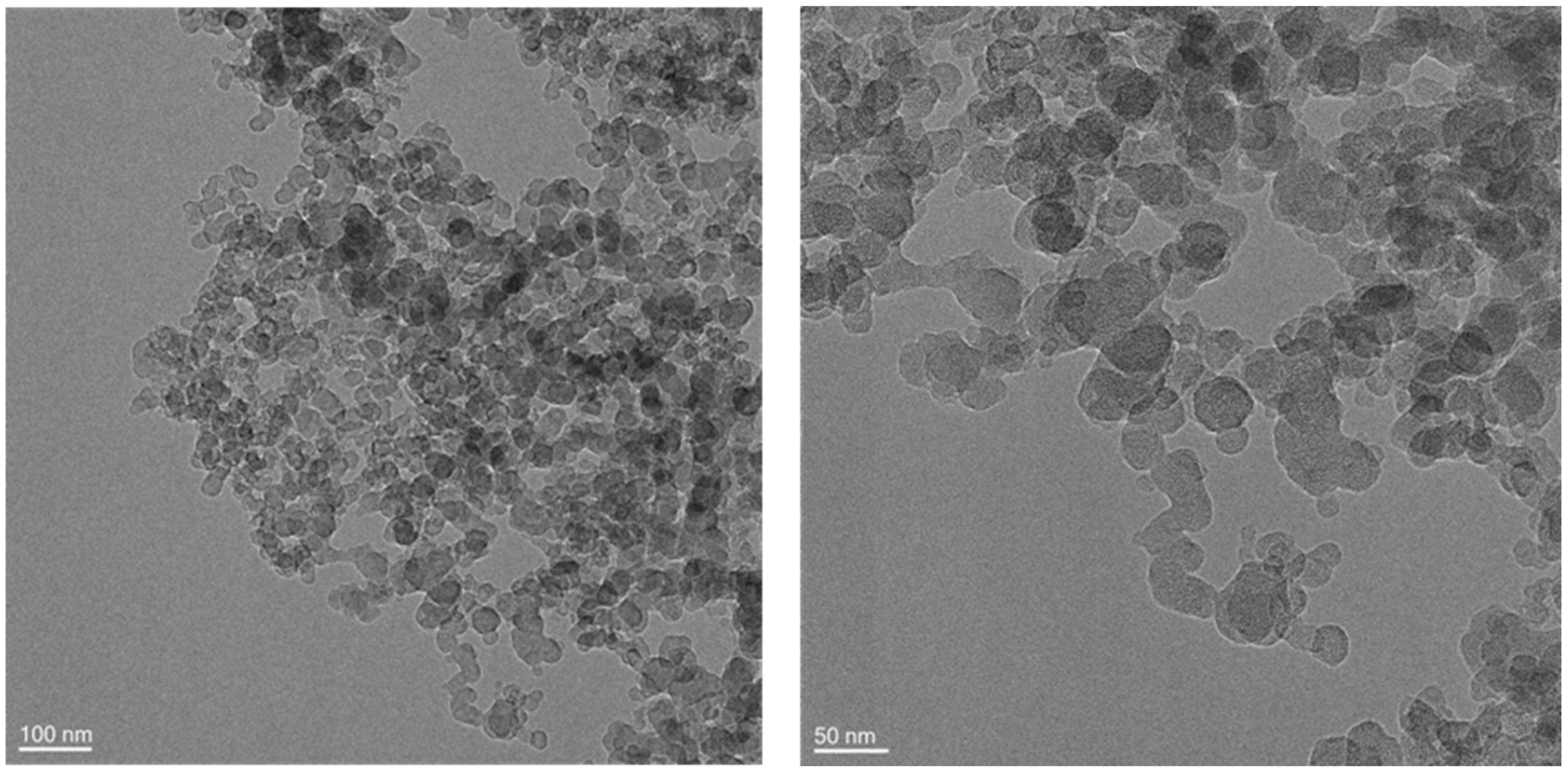
2.1.1. High-Resolution Transmission Electron Microscope

The microstructure of the particles was obtained by a Japanese JEOL JEM 2100F (The JEM-2100F is a multi-purpose 200 kV field emission analytical electron microscope manufactured by JEOL in Japan) transmission electron microscope (TEM) with a minimum resolution of 0.1 nm and an acceleration voltage of 200 kV. By using this equipment, images under a 5~500-nanometer scale can be obtained, and the agglomeration of particles and the morphology of primary particles can be obtained. Particulate samples for electron microscope analysis were prepared by ultrasonic method, and the samples were dispersed with anhydrous ethanol. The samples were ultrasonically shaken for 5~10 min, and a small amount of sample solution was dropped onto the TEM copper mesh. After drying, it was used for transmission electron microscope analysis.

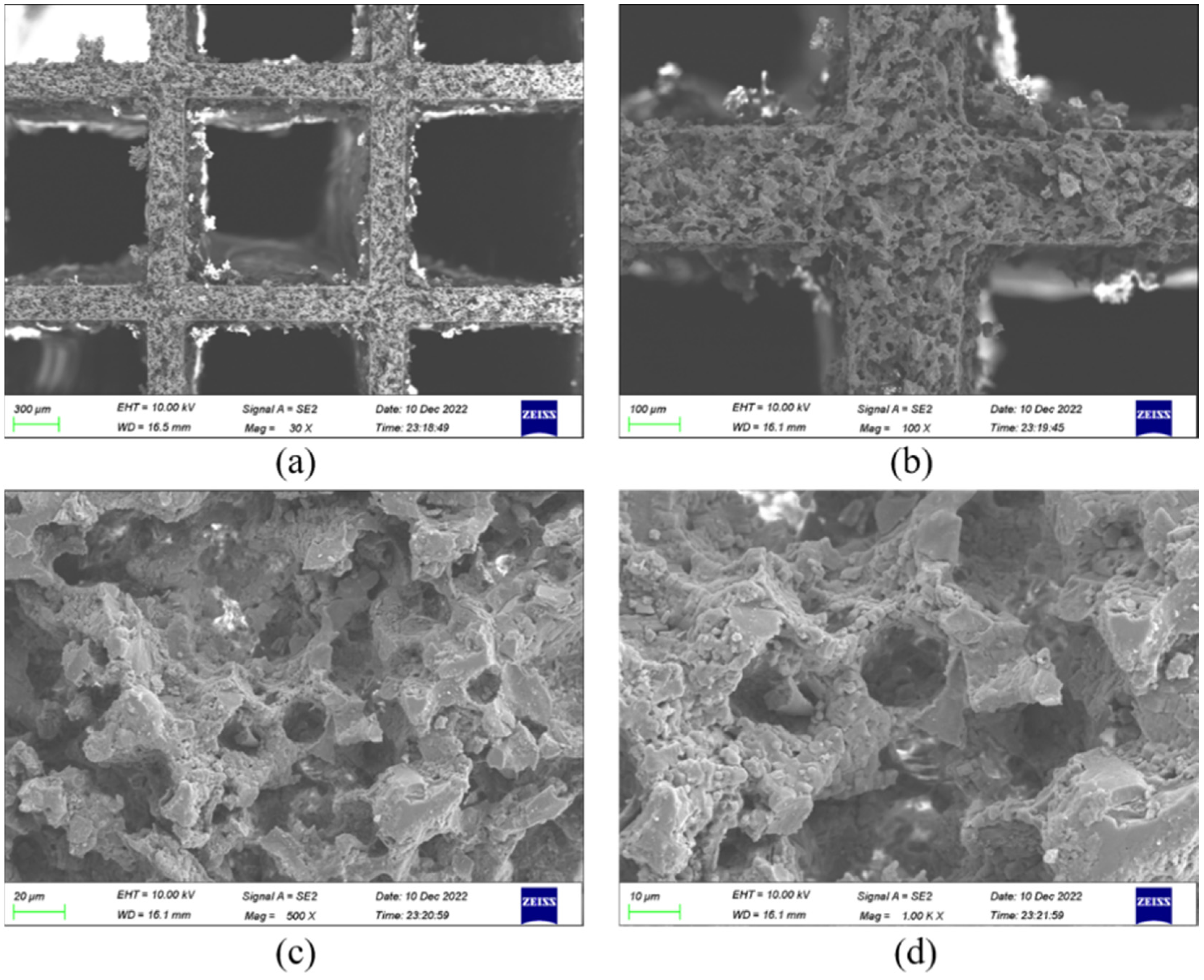
2.1.2. Scanning Electron Microscope

The two-dimensional macroporous structure of ZEISS Sigma 300 (The ZEISS Sigma 300 is manufactured by ZEISS in Germany) was observed by scanning electron microscopy. A small portion was cut from the filter and installed in epoxy. To make the surface of the sample completely smooth, SiC foil was used for grinding and polished with diamond foil and colloidal silica, and a thin gold layer of several nanometers was sputtered on the surface to prevent local charging, followed by scanning electron microscopy.

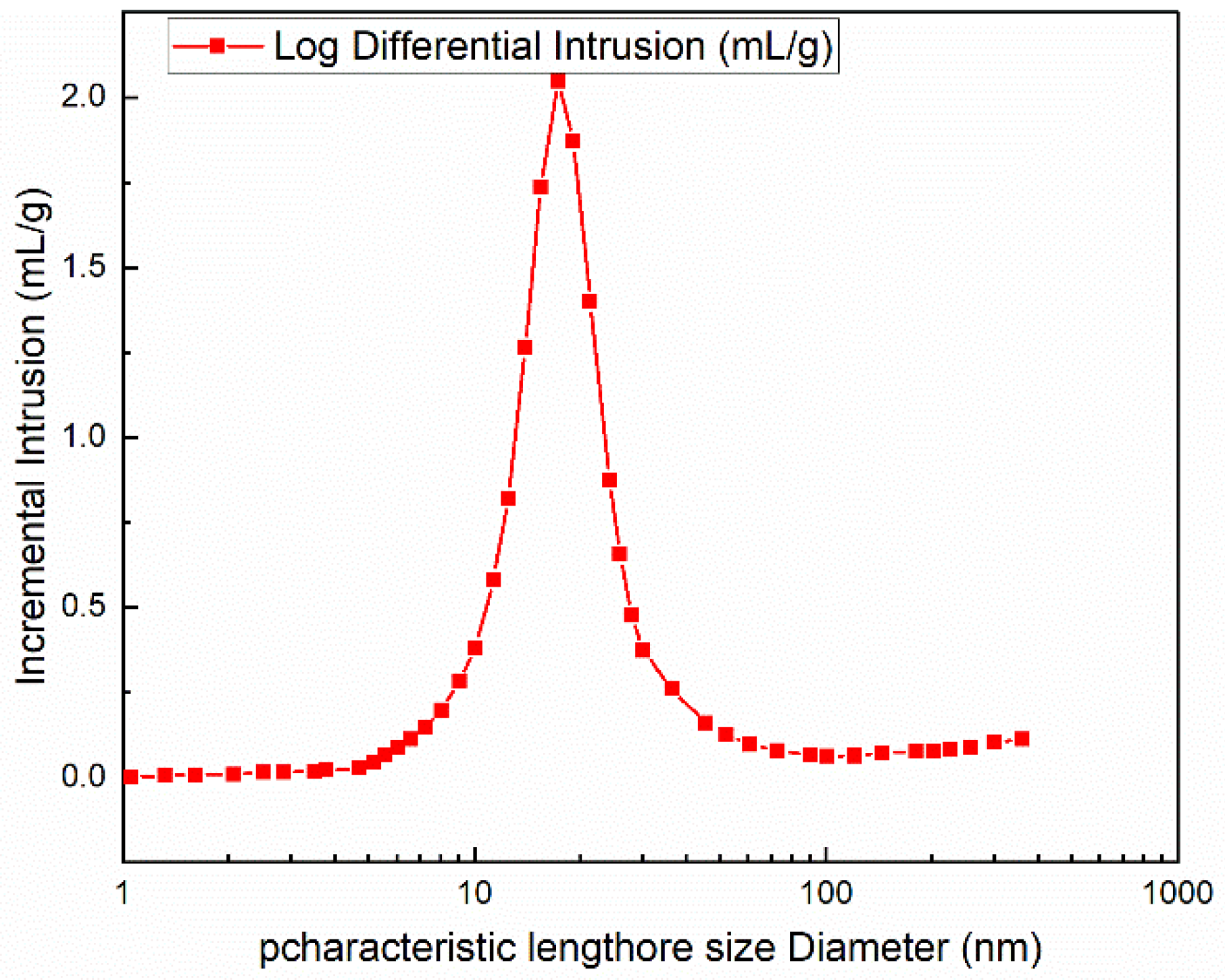
2.1.3. Mercury Intrusion Porosimetry

The mercury intrusion method provides a relatively fast and simple characterization of porous materials, and the size of the analysis sample is much smaller than the actual sample [17]. The test instrument used was a MicroMeritics AutoporeV 9620 from the United States, and samples were collected from different positions of the GPF to verify the uniformity of the substrate. The sample (size of 2 × 2 × 2 cm) was placed in a measuring chamber, degassed, and filled with mercury in the chamber. Subsequently, the pressure gradually increased (3–60,000 psi), mercury invaded the pores in the sample, and the pore size could be directly calculated by the Washburn equation.

2.2. Fractal Analysis

2.2.1. Particle Fractal

The aggregates of particles are irregular structures formed by a large number of primary particles. The fractal dimension Df of aggregates indicates the compactness of particles. The fractal dimension is related to the structure of aggregates. The larger the dimension, the denser the structure of aggregates, and the higher the overlap between primary particles [18,19].
To quantify the morphology of these aggregates, ImageJ software was used to measure the average diameter Dp of the primary particles that are easy to identify. According to the study of Farias [20], the calculation formula containing the fractal dimension Df is shown in Equation (1):
N p = k f D g D p D f
In the formula, kf is the fractal factor, Dg is the rotational diameter of particle aggregates, the average diameter of primary particles of Dp particles, and Np is the total number of primary particles:
N p = A a A p a
In the formula, Aa is the projection area of the particle, Ap is the primary particle projection area, and a is the empirical index of the projection area, which is 1.09 according to the literature [21]. The relationship between the particle rotation diameter and the maximum projection length L is shown in Equation (3):
L D g = 1.50 ± 0.05
Df and kg are determined by the slope and intercept of the fitted line, and the fitted line is obtained by plotting the logarithmic coordinate diagram of NpDg/Dp.

2.2.2. Fractal of Porous Media

In fractal objects, there is a basic relationship between the measurement N and the measured scale r. The scale relationship is shown in Equation (4):
M ( d ) d D
Porous media have fractal characteristics, such as pore surface and pore size distribution, reflecting their complex internal structure [22]. GPF is a solid fractal object coexisting with pores distributed inside it. Based on fractal theory, the ratio of cumulative pore number N to pore diameter is shown in Equation (5) [23]:
N d p o r e = d p o r e max d p o r e D a
Fractal dimension of pore area Da [24]:
D a = D E ln α ln d p o r e min / d p o r e max
Among them, DE is the Euclidean geometric dimension. In this paper, the Brownian diffusion of particles in the two-dimensional plane, DE = 2. The total pore area on the cross-section of porous media AD:
A D = π D a d p o r e max 2 4 α 2 D a 1 d p o r e min d p o r e max 2 D a
Fractal dimension Dt of tortuosity of pore channels in porous media:
L 0 = A
D t = 1 + ln τ ln ( L 0 / d p o r e )
The tortuosity is a parameter reflecting the bending degree of the flow path inside the porous medium. The tortuosity of the channel is defined as,
τ = L 0 d p o r e D t 1

2.3. Model Proposal

Model Assumptions

The commonly used unit-packed bed capture theory of the wall–flow honeycomb particle trap is based on the assumption that the theory is based on the Kuwabara flow field under low flow conditions. The capture unit is mainly regarded as an ideal ball to fill the porous medium, where the distance between the units is regarded as a pore. As shown in Figure 1, the porous medium is set as a spherical trap unit distributed in the wall of the GPF filter medium. The filtration efficiency of the entire GPF is determined by the capture efficiency of all ideal capture units.
Figure 2 shows the GPF test sample, Figure 3a shows the structure diagram of GPF, Figure 3b shows the CT scan image of GPF, and Figure 3c shows the SEM image of the GPF hole wall. When the particulate matter passes through the GPF internal channel with the airflow, it will be intercepted, and it can be seen that the GPF internal channel is irregular in shape. This uneven pore will affect the filtration efficiency to some extent. Generally, in the process of studying GPF porous media, the porosity (α), pore size (pore), and collector unit diameter (dc) are regarded as average by using the spherical packed bed theory:
The effect of GPF porous media on PM filtration efficiency depends on its microscopic geometric characteristics, such as porosity and average pore size [25]. In the packed bed theory of spherical particles, as shown in Figure 1, the wall is equivalent to multiple sets of spherical cell units, and the following assumptions are given: (i) the actual porosity is consistent with the porosity of the spherical cell unit; (ii) the specific surface area of the porous matrix is consistent with the specific surface area of the spherical cell unit [26]. Thus Equations (11)–(13) are obtained:
α = α w
k p o r e α d p o r e = 6 1 α w d f 2 d f 3
d c = 6 1 α w d p o r e k p o r e α w
Among them, the spherical unit is pore = 4, dc is the trap unit diameter, and pore is related to the internal pore model of GPF. In some studies, the pore model is cylindrical. When the GPF porous wall is loaded, PM accumulates around the collector unit until the pore unit is blocked [27]. The diameter pore of the aperture unit is expressed as follows:
d p o r e = d c 1 α 1 / 3
In a packed bed of spherical particles, the diameter dc of the collector unit can be obtained as a function of the pore, and the expression is shown in (15):
d c = 1.5 1 α α d p o r e

2.4. Filtering Scheme

At present, the size of inhalable particles produced by gasoline engines is usually much smaller than the size of the matrix hole. GPF does not filter particles directly but through deep bed filtration. The main filtration mechanism is interception, diffusion, and collision. The filtration mechanisms inside the GPF are shown in Figure 4, mainly including (a) Brownian diffusion, (b) direct interception, (c) inertial collision, and (d) gravity deposition [11]. The first three are the most important ones, which are mainly considered in this study.

2.4.1. Brownian Diffusion

Brownian diffusion filtration is the main filtration mechanism of particles, and the particle diameter is almost zero at a low flow rate. The Brownian motion experienced by particles is gradually affected as their size decreases. According to Lee and Gieseke [28], they analyzed and solved the convection and diffusion of particles in the packed pebble bed.
The filtration efficiency ED of a single trap unit with a Brownian diffusion mechanism depends on the Péclet number (Pe), which is related to the diffusion and advection processes. The calculation formula of Brownian diffusion capture efficiency ED is shown in Equation (16):
E D = 2 3 π 4 2 3 α Ku 1 3 P e 2 3
Péclet number: Pe is defined as the ratio of the diffusion rate of particles to the surface of the sphere to the rate of particles approaching the surface of the sphere in its cross-sectional area.
P e = d c U D D
U is the filtration rate (v/(1 − a), the ratio of inter-pore flow rate to porosity), and df is the diameter of the porous medium unit. DD is the particle diffusion coefficient [27]. The calculation formula is as follows:
D D = k B T C c 3 π μ g d p
where kB is the Boltzmann constant, dp is the particle diameter, T is the exhaust gas temperature flowing through the wall, and ug is the dynamic viscosity of the exhaust gas. The Stokes–Cunningham factor (Cc) explains the slip fluid dynamics. In this case, Cc is calculated from the Knudsen number Kn (λ refers to the average free path of gas) and the average pore size of GPF porous media [25]. Cc is denoted by,
C c = 1 + 1.257 K n p + 0.4 K n p exp ( 0.55 K n p )
Kn: Knudsen number:
K n = 2 λ d p o r e
The Kuwabara (Ku: Kuwabara’s number) dynamic factor number of the spherical trapping unit is [29],
K u = ln α 2 3 4 + α α 2 4

2.4.2. Direct Interception

The direct interception filtration mechanism is mainly that a single trap unit captures particles whose trajectory does not deviate from the streamline. If the particle is within the radius of the trap unit, the particle capture is called interception. The interception filtration efficiency ER (direct interception) of a single capture is calculated as Equation (22) [28].
E R = 3 1 α 2 K u N R 2 1 + N R n r
n r = 1 + 2 α 3 1 α
NR is the interception coefficient: the ratio of particle diameter to fiber diameter.
N R = d p d c

2.4.3. Inertial Impaction

The inertial filtering mechanism is related to the fact that the particle cannot change its trajectory when the particle streamlines approach the trap unit. This filtration mechanism is most important in large-diameter particles, but it is also controlled by velocity. Therefore, the inertial filtration efficiency EI of a single trap unit is a function of the Stokes number [27]:
E I = S t k a b + S t k a
The correlation experiment of the collection efficiency obtained by the inertial EI determines that the coefficients a and b are in the same form, where a = 2.4363 and b = 0.7817. ρp describes the density of ideal spherical particles with a particle size as the flow diameter. The calculation formula of the Stokes number Stk is shown in Equation (26):
S t k = C c ρ p U d p 2 9 μ g α d c
ρp: The density of ideal spherical particles with a particle size as flow diameter is described.

2.5. Modified Model

2.5.1. Particle Parameter Correction

Gasoline engine particulate matter has fractal morphological characteristics, and the value of fractal dimension Df can represent the agglomeration length of primary particles. Previous studies have shown that the most important components of inhalable particles are soot and SOF, and each particle can be considered as an aggregate of primary particles. As shown in Figure 5, the particles can be equivalent to a spherical structure; the core is soot, and the shell is the soluble organic fraction (SOF).
Particle aggregates have fractal characteristics. Studies have shown that the ratio of particle aggregate diameter to rotary diameter satisfies the following functional relationship [30]:
d g , m o b d g , g y r = f K n , D f , d p
In the formula, dg,mob is the migration diameter of fractal aggregates, dg,gyr is the rotational diameter of particles, Df is the fractal dimension of particle aggregates, and dp is the primary particle diameter of aggregates.
The relationship between particle rotation diameter and average diameter [31]:
d p , g y r = d p 2 + 1 N i = 1 N r i r G 1 2
r G = 1 N i = 1 N r i
where dp is the primary particle, ri and rG define the position of the center and the center of gravity of the principal particle of a cluster composed of N identical particles, respectively.
According to the research results of Schmindt-Ott [32], the mechanical mobility of particles and the diameter of rotation satisfy a certain functional relationship. Combined with the research of Wang and Sorensen [33], the following relationship is obtained:
(1) Fractal aggregate migration equivalent diameter:
d g , m o b d g , g y r = 0.43 D f , K n 1 d g , m o b d g , g y r = 1.29 d p 2 ( K n 1 ) + 0.43 D f λ d p 2 K n λ d p / 2 , 1 < K n 2 λ d p
The equivalent diameter of fractal aggregate migration is substituted into the correction of the particle diffusion coefficient:
D D = k B T C c 3 π μ g d g , m o b
(2) Spherical shell diameter of fractal aggregates [34]:
d g , o u t = D f + 2 D f d g , g y r
The interception coefficient is substituted into the fractal aggregate spherical shell diameter after correction:
N R = d g , o u t d c
(3) Mass equivalent diameter of fractal aggregates [35]:
d g , m a s = N 1 3 d p
N: Primary particle number.
In the inertial collision mechanism, the Stokes number needs to be substituted into the mass equivalent diameter and shell equivalent diameter correction of fractal aggregates:
S t k = 1 9 C c ρ p U d g , m a s 2 μ g d c

2.5.2. Non-Uniform Porous Media

The most common structure of the particle filter is the wall–flow structure, which is composed of a set of alternately blocked porous wall channels. The inlet is blocked behind, and the outlet is blocked in front. The exhaust gas from the engine enters the trap through the inlet channel and is discharged through the outlet channel. The porous medium wall between the inlet and outlet channels can capture the particles in the exhaust gas. The deposition of particles in the porous space of the wall leads to an increase in filtration efficiency but also increases the pressure drop of the filter. As this process continues, further in-wall particle deposition is prevented because the deposited particles lead to pore closure.
Figure 6 is an SEM image of the GPF sample. It can be seen that the internal porous medium is non-uniform. In Figure 6, a to d respectively represent images at different scales of 300 μm, 100 μm, 20 μm, and 10 μm. From the (6d) image, it can be seen that the holes on the GPF filter wall are irregular and unevenly distributed. It is these holes that trap particles. Therefore, we need to consider the non-uniformity of the pore size of the porous medium. The shape of these pores, the connection between the pores, and other factors will affect the filtration of GPF. The porosity and pore size of GPF is relatively easy to obtain by technical measurement. In addition, permeability is also closely related to pore size and porosity. Therefore, we consider introducing the pore area and the fractal characteristics of the pores into the model to re-characterize the porosity, pore size, trapping unit, and permeability to describe the inhomogeneity of the actual GPF filter medium structure.
Based on this, Gong and Rutland et al. proposed a dynamic inhomogeneous model for GPF [7]. The pore size distribution is converted into a probability density function using the lognormal fitting, and the corresponding trap unit PDF function is obtained:
p d f d c = 2 α 3 1 α p d f d p o r e
ldc: Root of average area:
l d c = p d f d c d c 2 d d c 1 2
The dominant mechanism can be judged by the Knudsen number Kn in different pore structures. Kn is defined as the ratio of the spatial characteristic length to the free path of the gas molecule, that is,
K n = 2 λ d p o r e
The effective diffusion coefficient of porous media is shown in Equation (38):
D D = C c 1 12 p m 2 D a + D t 8 R T π M 10 k B T 2 π P d p 2 2 D a + D t d p o r e min 2 D a + D t + 1 128 μ g 3 D a + D t d p o r e max 3 D a + D t 0.1 k B T 2 π P d p 2 3 D a + D t
pm is the diffusion pressure of particles; M is the mass of particles, kg/mol; r is gas constant, R = 8.314 J/(mol·K); T is ambient temperature; and P is atmospheric pressure.

2.6. Modified Model

2.6.1. Filtering Effectiveness

Considering that any deposition mechanism is independent of other mechanisms, the filtration efficiency of a single trap is calculated by single fiber mechanism filtration. The main mechanisms of classical filtration theory include Brownian diffusion (ED), direct interception (ER), and inertial deposition (EI). Assuming that all mechanisms are independent of each other and the efficiency is the combined effect of multiple filtration mechanisms, the filtration efficiency of a single capture unit is [11],
E = 1 1 E D 1 E R 1 E I
Wall–flow filter filtration data was published and verified using engine test benches or particle generators. The description of porous media as a sphere-trapping unit with the same hydrodynamic diameter as the pore network is the basis of all these models. This assumption can predict the particle collection efficiency FE of a single sphere (unit collector) with a diameter of DC and then integrate it on the filter wall [36]. Equation (40) indicates that the filtration efficiency due to the contribution of each trap unit on the filter wall with a medium thickness Lh and porosity is,
FE = 1 exp 3 1 α 2 α E L h d c
The method of describing the microstructure of the filter only by the average pore size and porosity is not enough for the operation accuracy of the GPF. The deep filtration of GPF is very sensitive to the microstructure of the filter. Based on the heterogeneous model, including pore size distribution developed by Gong and Rutland, the fractal model of the GPF filter is obtained by rewriting the particle equation equivalent diameter (DP) with the fractal dimension (Df) of particle aggregates and filter fiber diameter (dc) with the fractal dimension (Dt) of filter solid phase pore size:
FE = 1 exp 3 1 α 2 α E ( D f ) L h D a d c ( D t )

2.6.2. Pressure Drop

Pressure drops at both ends of the particle filter according to Darcy’s law; the formula for describing the pressure drop of porous media is as follows:
Δ P = 1 K F E U L
The Kozeny–Carman equation is a semi-empirical model with a constant k. Although the equation is only applicable to the permeability calculation of the ideal model, the constant k is not constant. It is the basic value to describe the correlation between pore structure parameters and permeability. In recent years, many scholars have improved the classical KC equation and proposed a series of permeability calculation models suitable for different types of porous media. Among them, the proposed double fractal permeability model is the most popular [37]. The specific expression of the model is shown in (43):
K = π D a 1 D t / 2 128 4 2 D a 1 D t / 2 3 D a + D t α 1 α 1 D t / 2 d p o r e max 2
The optimization of porous media parameters needs to consider both filtration efficiency and pressure drop.

3. Results and Discussion

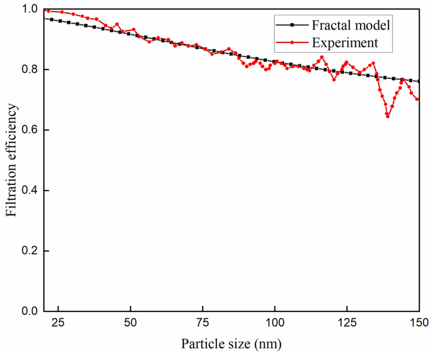
3.1. Model Verification

According to the classical filtration theory, the filtration mechanism of particles in the filtration process is related to the corresponding coefficient of each filtration mechanism. As shown in Figure 7, when using the unit-packed bed capture theory, it is assumed that the particles are spherical, and each capture mechanism is calculated by particle diameter. However, in the actual filtration process, the GDI gasoline engine particles are irregular in shape, various forms of aggregates are formed, and the aggregates are fractal. The classical filtration theory based on spherical particles has some limitations. Therefore, to describe the behavior of particles under different mechanisms, we introduce three parameters, i.e., particle migration equivalent diameter, mass equivalent diameter, and shell equivalent diameter, which is calculated based on the fractal dimension of particles. They characterize the motion characteristics, mass characteristics, and size characteristics of particles in the airflow. For different particle migration mechanisms, we substitute the corresponding fractal equivalent diameter into the calculation formula. The correction process of the classical filtration theory is as follows:
The common method for measuring the pore size distribution of the medium is the mercury intrusion method. This method injects mercury into the porous medium at a certain pressure. By measuring the mercury intrusion volume, the mercury intrusion volume curve in the medium is obtained, and then it is converted into a pore-size distribution curve, as shown in Figure 8. According to the data measured by the porosity measurement method, the pore size distribution generally follows a lognormal distribution. In the pore size distribution curve obtained by the experiment, the pore size corresponding to the peak value is the pore size corresponding to the mercury intrusion volume of 50%. The aperture used in the classical filtration theory model is the aperture corresponding to the peak. Table 1 shows the parameters of GPF obtained by the mercury intrusion method.
The model verification experiment verifies the fractal filtration model based on the experimental data of GPF samples under steady-state working conditions and the fractal dimension usage diagram of the particle size segment. The filtration efficiency of the shape filter model is compared with the experimental data. As shown in Figure 9, the fractal expansion model can well capture the trend and magnitude of experimental filtration efficiency. The difference between experimental and simulated data is small. Due to the low number of particles in the initial phase, the simulation prediction at the end of the operating conditions is very similar to the beginning of the simulation, and the particle size filtration efficiency predicted by the model is closer to the experimental data throughout the filtration process. The trend and size of the experimental data are highly correlated with the model. In summary, the overall filtration efficiency and experimental data of the fractal expansion model in different particle size distributions are basically consistent.

3.2. Effect of Microstructure Parameters on Filtration Efficiency
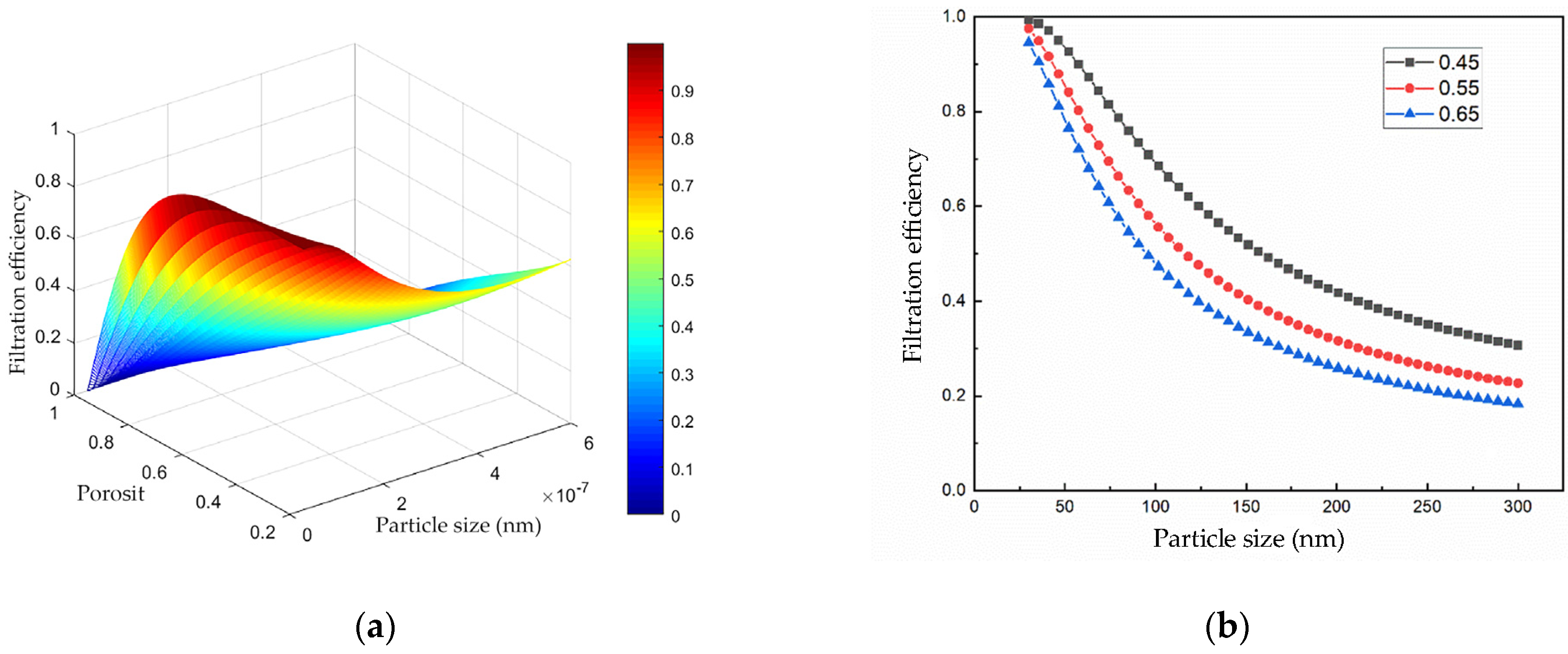
The filtration efficiency of GPF is mainly related to its structural parameters, including porosity (α), pore size (pore), and medium thickness (Lh). The filtration performance of the trap model is closely related to the unit trap, and the diameter of the trap unit is calculated by porosity and pore size.

3.2.1. Porosity

When the pore diameter is 10um, the thickness of the filter medium is 1.65 mm, the filtration flow rate is 3 cm/s, and the exhaust temperature is 400 °C. Figure 10a,b shows the influence of the porosity of the trap on the filtration efficiency of particles with different sizes. When the porosity gradually decreases, the filtration efficiency of particles with different sizes increases. Three porosities of 0.45, 0.55, and 0.65 were selected, respectively. According to the given GPF structure parameters, it was found that when the porosity was 0.65 and 0.45, the corresponding filtration efficiency was lower than that when the porosity was 0.45. In the case of the same average pore size, the smaller the porosity, the more pores in the medium, and the easier the particles are captured. The number of particles passing through each pore will also decrease. At the same time, when the porosity is small, the number of particles allowed to pass through will be less, thus having higher filtration efficiency.

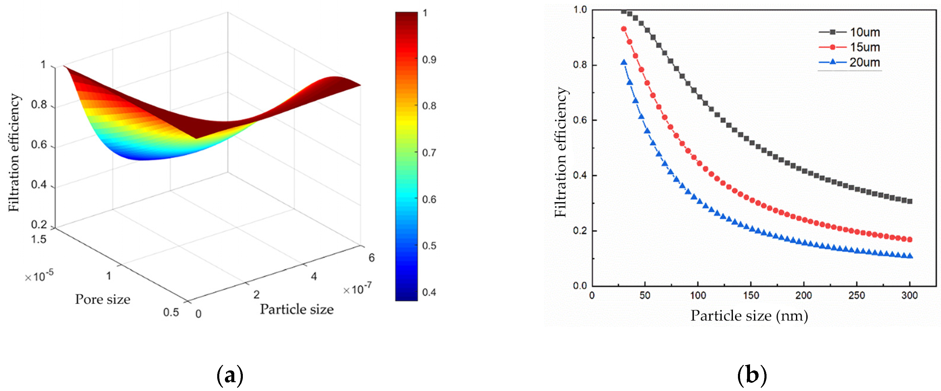
3.2.2. Pore Diameter

When the porosity is 0.45, the thickness of the filter medium is 1.65 mm, the filtration flow rate is 3 cm/s, and the exhaust temperature is 400 °C. It can be seen from Figure 11a,b that when the pore size is small, the filtration efficiency of all particle sizes increases with the decrease of the average pore size. As the average pore size increases, the trend of filtration efficiency also decreases. Three GPF aperture parameters of 10, 15, and 20 μm were selected. When the aperture was small, the filtration efficiency decreased slowly. This is because when the porosity remains unchanged, the smaller the average pore size means that for the same filter medium wall thickness, the filter medium has more pores, resulting in more pores that can capture more particles at the same time.

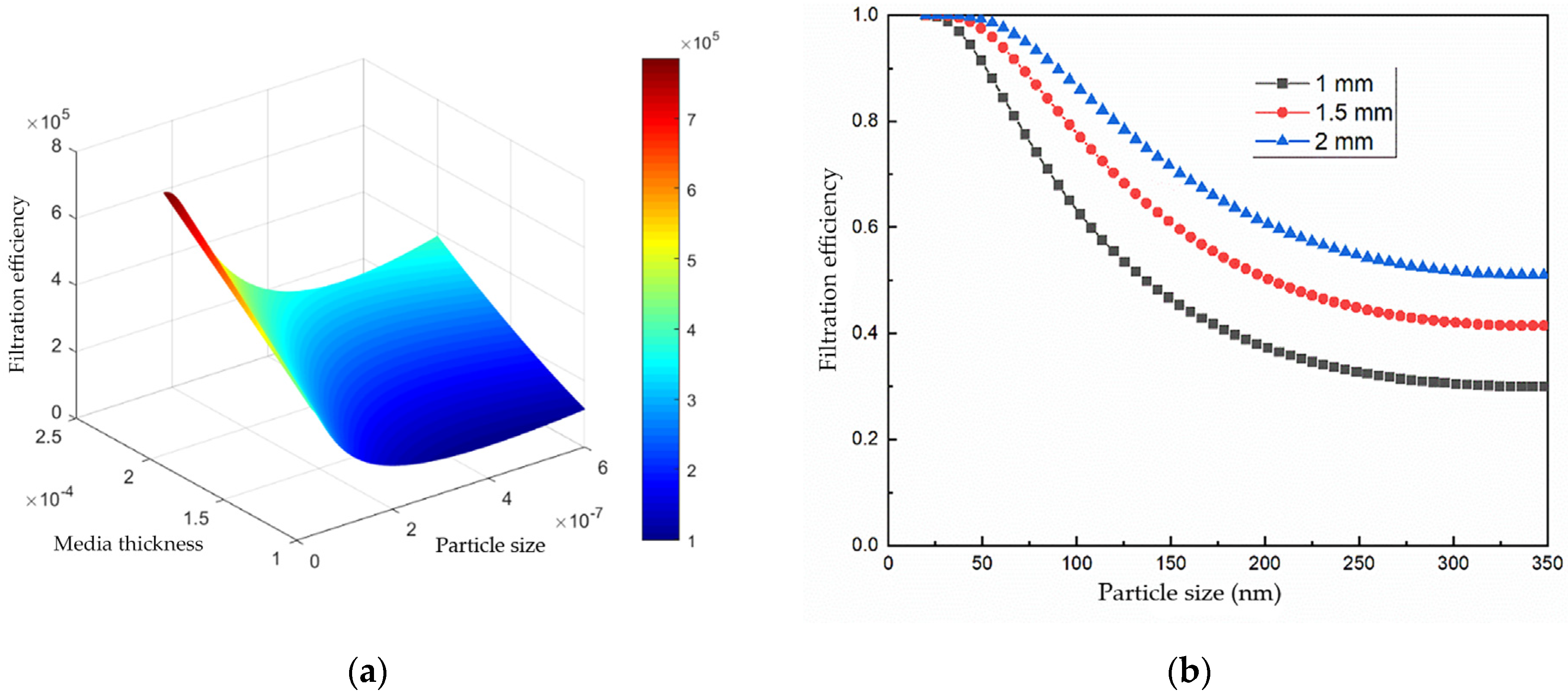
3.2.3. Media Thickness

When the porosity is 0.45, the pore size is 10 um, the filtration flow rate is 3 cm/s, and the exhaust temperature is 400 °C. It can be seen from Figure 12a,b that when the thickness of the medium gradually increases, the filtration efficiency of particles of all particle sizes also increases. Three filter media thicknesses of 1 mm, 1.5 mm, and 2 mm were selected. It was found that too large a thickness would lead to increased resistance. When the thickness of porous media is too large, the degree of increase in filtration efficiency will gradually decrease. For particles of different sizes, the thickness of porous media may have different effects on filtration efficiency. For large particles, the thicker porous media can effectively filter them out, while for small particles, the increase in the thickness of the filter medium has little effect on the filtration efficiency.

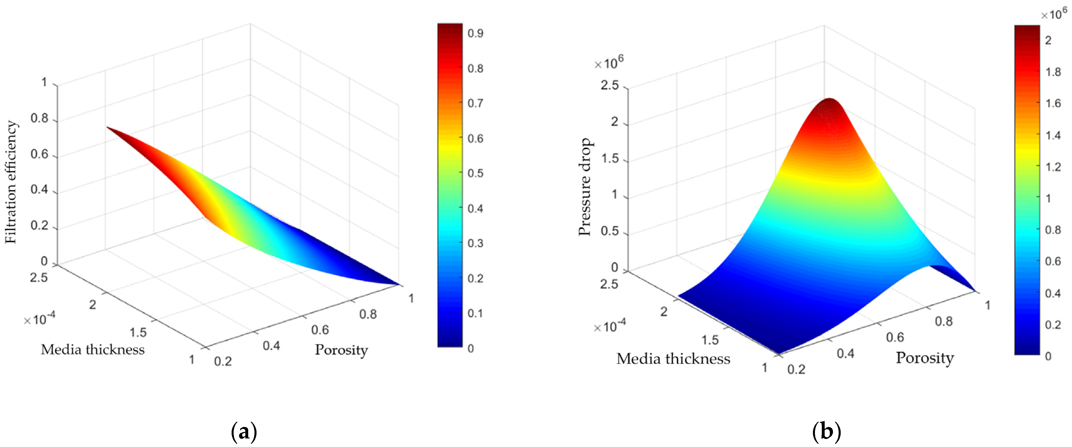
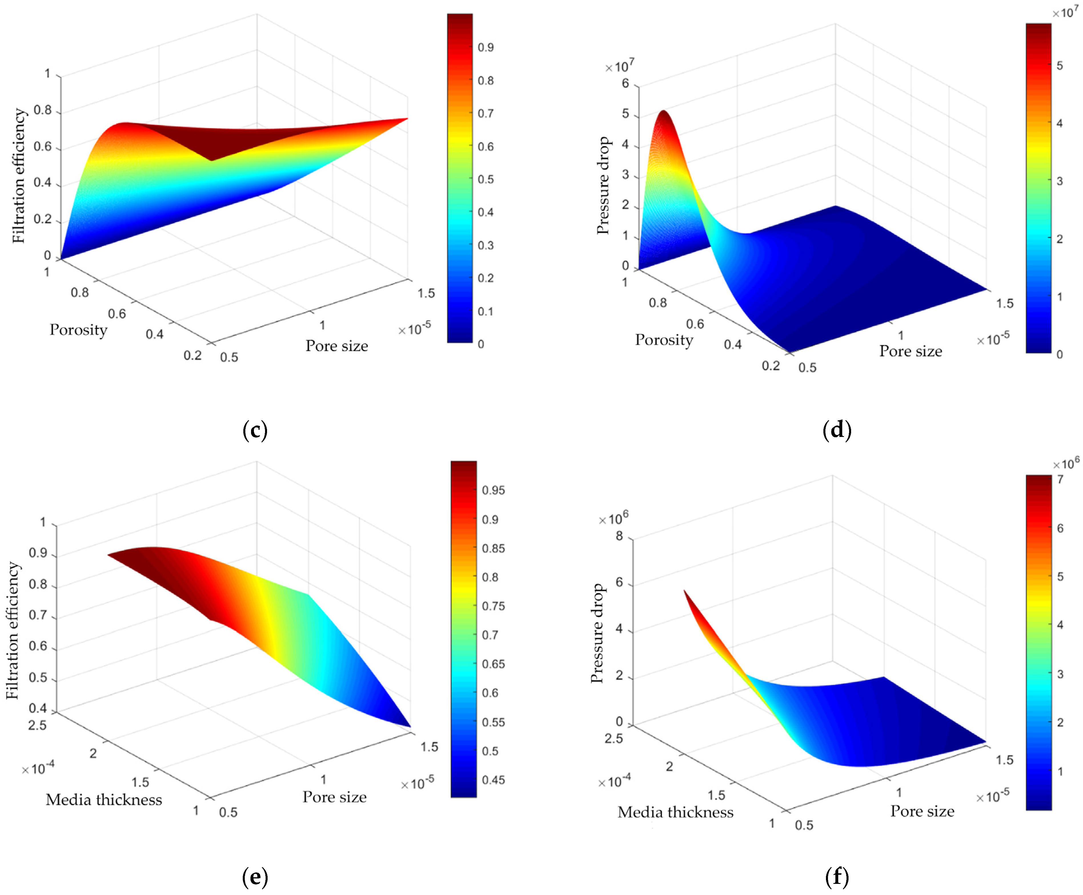
3.3. Simulation of Filtration Efficiency and Pressure Drop

Filtration efficiency and pressure drop are contradictory. Ideally, low-pressure drop and high filtration efficiency are obtained. Assuming that the particle diameter is 200 nm, the particle density is 1.2 g/cm3, the temperature is 400 degrees Celsius, and the pressure drop is calculated according to Darcy’s law. Considering the influence of porosity, pore diameter, and medium thickness of GPF porous media on filtration efficiency, we find that these three parameters have a great influence on the two performance indexes of capture efficiency and pressure drop. It can be seen from Figure 13a,b that the larger the medium thickness and the smaller the porosity, the higher the capture efficiency and the lower the pressure drop. At the same pore size, as the thickness of the medium increases, the porosity is small, and the filtration efficiency will increase. Because the smaller the porosity, the more particles exist in the pores, and the particles find it more difficult to pass through the porous medium, resulting in increased filtration efficiency. But at the same time, low porosity also leads to less pressure drop because the fluid will encounter less resistance when passing through porous media.
It can be seen from Figure 13c,d that as the porosity and pore size decrease, the filtration efficiency of GPF increases, and the pressure drop decreases. In the case of the same porous medium, smaller porosity and pore size will form more ‘obstacles’ and increase the number of collisions between particles and the medium, thereby increasing the residence time of particles in the medium and increasing the filtration efficiency. With the decrease of porosity and pore size, the pressure drop of GPF decreases because small pores can form more pores and channels, thereby increasing the permeability and flux inside the medium and reducing resistance and pressure drop. In addition, small pores can form more ‘obstacles’ and increase the number of collisions between particles and media, making it easier for particles to deposit on the surface of the medium, reducing the resistance inside the medium, thereby reducing the pressure drop.
It can be observed from Figure 13e,f that when the porosity is constant, the filtration efficiency of GPF increases with the increase of medium thickness and the decrease of pore size, but the pressure drop also increases. This is because when the medium thickness increases and the pore size decreases, the residence time and deposition probability of particles in the medium will also increase so that the filtration efficiency will increase accordingly. However, increasing the thickness of the medium or reducing the pore size will also increase the resistance inside the medium and hinder the flux of particles, thereby increasing the pressure drop. On the other hand, at the same porosity, as the pore diameter decreases, the filtration efficiency will increase because the small pore size can capture smaller particles, and more particles will be trapped by inertial deposition. But at the same time, the small aperture also leads to an increase in pressure drop because the fluid will encounter more resistance when passing through the small aperture.

4. Conclusions

In this paper, the improved fractal extended numerical model is used to simulate the porosity, pore diameter, and medium thickness of porous media to explore their influence on filtration efficiency. The porosity, pore size, and medium thickness of GPF porous media have a great influence on its filtration efficiency and pressure drop. When designing GPF, it is necessary to select appropriate porous media parameters according to the requirements of emission regulations and the performance characteristics of the engine. The following is a discussion of the effects of these three parameters on GPF performance: Porosity is an important parameter affecting GPF filtration efficiency and pressure drop. In general, the greater the porosity, the greater the chance of particles passing through the medium, the lower the filtration efficiency, but the smaller the pressure drop. The pore size affects the important parameters of GPF filtration efficiency and pressure drop. The smaller the pore size, the fewer the particles passing through the GPF, but the pressure drop will also increase. The greater the thickness of the medium, the more particles can be captured, but the pressure drop will also increase. Therefore, it is necessary to select the appropriate medium thickness to obtain the best filtration efficiency and pressure drop under the premise of meeting the emission regulations.
In summary, the thickness of porous media has an important influence on filtration efficiency. In the design of GPF filtration, a variety of factors need to be considered, including the thickness of porous media, media materials, porosity, and other parameters, to achieve the best filtration effect.

Author Contributions

Conceptualization, Y.L. and H.W.; methodology, H.W.; software, H.W.; validation, Y.L., H.W. and H.Y.; formal analysis, Y.L.; investigation, Y.L.; resources, Y.L. and H.W.; data curation, Y.L. and H.W.; writing—original draft preparation, H.W.; writing—review and editing, Y.L. and H.W.; visualization, H.Y.; supervision, H.Y.; project administration, H.Y.; funding acquisition, Y.L. All authors have read and agreed to the published version of the manuscript.

Funding

This research was funded by the Yunnan Provincial High-Level Talent Support Project, grant number YNQR-CYRC-2019-001.

Institutional Review Board Statement

Not applicable.

Informed Consent Statement

Not applicable.

Data Availability Statement

Not applicable.

Conflicts of Interest

The authors declare no conflict of interest.

References

  1. Millo, F.; Andreata, M.; Rafigh, M.; Mercuri, D.; Pozzi, C. Impact on vehicle fuel economy of the soot loading on diesel particulate filters made of different substrate materials. Energy 2015, 86, 19–30. [Google Scholar] [CrossRef]
  2. Jang, J.; Lee, J.; Choi, Y.; Park, S. Reduction of particle emissions from gasoline vehicles with direct fuel injection systems using a gasoline particulate filter. Sci. Total Environ. 2018, 644, 1418–1428. [Google Scholar] [CrossRef]
  3. Kontses, A.; Triantafyllopoulos, G.; Ntziachristos, L.; Samaras, Z. Particle number (PN) emissions from gasoline, diesel, LPG, CNG and hybrid-electric light-duty vehicles under real-world driving conditions. Atmos. Environ. 2020, 222, 117126. [Google Scholar] [CrossRef]
  4. Yusuf, A.A.; Inambao, F.L. Effect of cold start emissions from gasoline-fueled engines of light-duty vehicles at low and high ambient temperatures: Recent trends. Case Stud. Therm. Eng. 2019, 14, 100417. [Google Scholar] [CrossRef]
  5. He, L.; Hu, J.; Zhang, S.; Wu, Y.; Zhu, R.; Zu, L.; Bao, X.; Lai, Y.; Su, S. The impact from the direct injection and multi-port fuel injection technologies for gasoline vehicles on solid particle number and black carbon emissions. Appl. Energy 2018, 226, 819–826. [Google Scholar] [CrossRef]
  6. Chan, T.W.; Saffaripour, M.; Liu, F.; Hendren, J.; Thomson, K.A.; Kubsh, J.; Brezny, R.; Rideout, G. Characterization of Real-Time Particle Emissions from a Gasoline Direct Injection Vehicle Equipped with a Catalyzed Gasoline Particulate Filter During Filter Regeneration. Emiss. Control Sci. Technol. 2016, 2, 75–88. [Google Scholar] [CrossRef]
  7. Gong, J.; Rutland, C.J. Filtration Characteristics of Fuel Neutral Particulates Using a Heterogeneous Multiscale Filtration Model. J. Eng. Gas. Turbines Power 2015, 137, 111507. [Google Scholar] [CrossRef]
  8. Gong, J.; Rutland, C.J. PDF-Based Heterogeneous Multiscale Filtration Model. Environ. Sci. Technol. 2015, 49, 4963–4970. [Google Scholar] [CrossRef]
  9. Gong, J.; Viswanathan, S.; Rothamer, D.A.; Foster, D.E.; Rutland, C.J. Dynamic Heterogeneous Multiscale Filtration Model: Probing Micro- and Macroscopic Filtration Characteristics of Gasoline Particulate Filters. Environ. Sci. Technol. 2017, 51, 11196–11204. [Google Scholar] [CrossRef] [PubMed]
  10. Gong, J.; Stewart, M.L.; Zelenyuk, A.; Strzelec, A.; Viswanathan, S.; Rothamer, D.A.; Foster, D.E.; Rutland, C.J. Importance of filter’s microstructure in dynamic filtration modeling of gasoline particulate filters (GPFs): Inhomogeneous porosity and pore size distribution. Chem. Eng. J. 2018, 338, 15–26. [Google Scholar] [CrossRef]
  11. Serrano, J.R.; Climent, H.; Piqueras, P.; Angiolini, E. Filtration modelling in wall-flow particulate filters of low soot penetration thickness. Energy 2016, 112, 883–898. [Google Scholar] [CrossRef]
  12. Viswanathan, S.; Rothamer, D.; Zelenyuk, A.; Stewart, M.; Bell, D. Experimental investigation of the effect of inlet particle properties on the capture efficiency in an exhaust particulate filter. J. Aerosol Sci. 2017, 113, 250–264. [Google Scholar] [CrossRef]
  13. Yang, Y.; Rutland, C.; Rothamer, D. Study of the Deep-Bed Filtration Using Pore Filtration Model (PFM). SAE Int. J. Fuels Lubr. 2018, 11, 287–299. [Google Scholar] [CrossRef]
  14. Walter, R.; Neumann, J.; Hinrichsen, O. Extended Model for Filtration in Gasoline Particulate Filters under Practical Driving Conditions. Environ. Sci. Technol. 2020, 54, 9285–9294. [Google Scholar] [CrossRef] [PubMed]
  15. Walter, R.; Neumann, J.; Velroyen, A.; Hinrichsen, O. Applying 3D X-ray Microscopy to Model Coated Gasoline Particulate Filters under Practical Driving Conditions. Environ. Sci. Technol. 2022, 56, 12014–12023. [Google Scholar] [CrossRef] [PubMed]
  16. Li, Z.; Shen, B.; Zhang, Y.; Kong, X.; Li, S. Simulation of deep-bed filtration of a gasoline particulate filter with inhomogeneous wall structure under different particle size distributions. Int. J. Engine Res. 2021, 22, 2107–2118. [Google Scholar] [CrossRef]
  17. Václavík, M.; Plachá, M.; Kočí, P.; Svoboda, M.; Hotchkiss, T.; Novák, V.; Thompsett, D. Structure characterisation of catalytic particulate filters for automotive exhaust gas aftertreatment. Mater. Charact. 2017, 134, 311–318. [Google Scholar] [CrossRef]
  18. Köylü, Ü.Ö.; Faeth, G.M.; Farias, T.L.; Carvalho, M.G. Fractal and projected structure properties of soot aggregates. Combust. Flame 1995, 100, 621–633. [Google Scholar] [CrossRef]
  19. Swapna, M.S.; Devi, H.V.S.; Raj, V.; Sankararaman, S. Fractal and spectroscopic analysis of soot from internal combustion engines. Eur. Phys. J. Plus 2018, 133, 106. [Google Scholar] [CrossRef]
  20. Farias, T.L.; Köylü, Ü.Ö.; Carvalho, M.G. Effects of polydispersity of aggregates and primary particles on radiative properties of simulated soot. J. Quant. Spectrosc. Radiat. Transf. 1996, 55, 357–371. [Google Scholar] [CrossRef]
  21. MEGARIDIS, C.M.; DOBBINS, R.A. Morphological Description of Flame-Generated Materials. Combust. Sci. Technol. 1990, 71, 95–109. [Google Scholar] [CrossRef]
  22. Yu, B.; Cheng, P. A fractal permeability model for bi-dispersed porous media. J. Heat. Mass. Transf. 2002, 45, 2983–2993. [Google Scholar] [CrossRef]
  23. Tan, X.H.; Liu, C.Y.; Li, X.P.; Wang, H.Q.; Deng, H. A stress sensitivity model for the permeability of porous media based on bi-dispersed fractal theory. Int. J. Mod. Phys. C 2018, 29, 1850019. [Google Scholar] [CrossRef]
  24. Yu, B.; Li, J. Some Fractal Characters of Porous Media. Fractals 2011, 9, 365–372. [Google Scholar] [CrossRef]
  25. Bollerhoff, T.; Markomanolakis, I.; Koltsakis, G. Filtration and regeneration modeling for particulate filters with inho-mogeneous wall structure. Catal. Today 2012, 188, 24–31. [Google Scholar] [CrossRef]
  26. Lee, J.M.; Sung, N.W.; Cho, G.B.; Oh, K.O. Performance of radial-type metal foam diesel particulate filters. Int. J. Automot. Technol. 2010, 11, 307–316. [Google Scholar] [CrossRef]
  27. Serrano, J.R.; Arnau, F.J.; Piqueras, P.; García-Afonso, Ó. Packed bed of spherical particles approach for pressure drop prediction in wall-flow DPFs (diesel particulate filters) under soot loading conditions. Energy 2013, 58, 644–654. [Google Scholar] [CrossRef]
  28. Lee, K.W.; Gieseke, J.A. Collection of aerosol particles by packed beds. Environ. Sci. Technol. 1979, 13, 466–470. [Google Scholar] [CrossRef]
  29. Kuwabara, S. The Forces experienced by Randomly Distributed Parallel Circular Cylinders or Spheres in a Viscous Flow at Small Reynolds Numbers. J. Phys. Soc. Jpn. 1959, 14, 527–532. [Google Scholar] [CrossRef]
  30. Bałazy, A.; Podgórski, A. Deposition efficiency of fractal-like aggregates in fibrous filters calculated using Brownian dy-namics method. J. Colloid. Interface Sci. 2007, 311, 323–337. [Google Scholar] [CrossRef]
  31. Penconek, A.; Jackiewicz, A.; Moskal, A. Penetration of Diesel Exhaust Particles (DEPs) through Fibrous Filters Produced Using Melt-Blown Technology. KONA Powder Part. J. 2015, 32, 184–195. [Google Scholar] [CrossRef]
  32. Kütz, S.; Schmidt-Ott, A. Use of a low-pressure impactor for fractal analysis of submicron particles. J. Aerosol Sci. 1990, 21, S47–S50. [Google Scholar] [CrossRef]
  33. Wang, G.M.; Sorensen, C.M. Diffusive mobility of fractal aggregates over the entire knudsen number range. Phys. Rev. E 1999, 60, 3036–3044. [Google Scholar] [CrossRef]
  34. Lattuada, M.; Wu, H.; Morbidelli, M. A simple model for the structure of fractal aggregates. J. Colloid. Interface Sci. 2003, 268, 106–120. [Google Scholar] [CrossRef] [PubMed]
  35. Gmachowski, L. Mechanism of shear aggregation. Water Res. 1995, 29, 1815–1820. [Google Scholar] [CrossRef]
  36. Konstandopoulos, A.G.; Johnson, J.H. Wall-Flow Diesel Particulate Filters—Their Pressure Drop and Collection Efficiency. J. Eng. 1989, 98, 625–647. [Google Scholar] [CrossRef]
  37. Xu, P.; Yu, B. Developing a new form of permeability and Kozeny–Carman constant for homogeneous porous media by means of fractal geometry. Adv. Water Resour. 2008, 31, 74–81. [Google Scholar] [CrossRef]
Figure 1. Spherical trapping unit hypothesis.
Atmosphere 14 01689 g001
Figure 2. GPF test sample.
Atmosphere 14 01689 g002
Figure 3. Microstructure of GPF (a) GPF structure simulation diagram, (b) GPF CT scan image, (c) GPF SEM scan image.
Atmosphere 14 01689 g003
Figure 4. Filtering mechanism (a) Brown diffusion, (b) Direct interception, (c) Inertial impaction.
Atmosphere 14 01689 g004
Figure 5. Schematic drawing of particle aggregates.
Atmosphere 14 01689 g005
Figure 6. GPF structure SEM images (Bar: (a) 300 μm (b) 100 μm (c) 20 μm (d) 10 μm).
Atmosphere 14 01689 g006
Figure 7. Particle aggregate schematic images.
Atmosphere 14 01689 g007
Figure 8. Pore size distribution.
Atmosphere 14 01689 g008
Figure 9. Verifying the filtering efficiency.
Atmosphere 14 01689 g009
Figure 10. Effect of porosity on filtration efficiency (a) Impact of porosity and particle size, (b) Different porosity levels.
Atmosphere 14 01689 g010
Figure 11. Effect of pore size on filtration efficiency (a) Effect of filtration efficiency at different pore and particle sizes, (b) Variation of filtration efficiency at different particle sizes.
Atmosphere 14 01689 g011
Figure 12. Effect of wall thickness on filtration efficiency. (a) Filtration efficiency at different media thicknesses and particle sizes, (b) Variation of filtration efficiency at different particle sizes.
Atmosphere 14 01689 g012
Figure 13. Analysis of filtration efficiency and pressure drop (a) Filtration efficiency at different media thicknesses and particle sizes, (b) Pressure drop at different media thicknesses and particle sizes, (c) Effect of filtration efficiency at different pore and particle sizes, (d) Effect of pressure drop at different pore and particle sizes, (e) Filtration efficiency at different media thicknesses and pore sizes, (f) Pressure drop at different media thicknesses and pore sizes.
Atmosphere 14 01689 g013aAtmosphere 14 01689 g013b
Table 1. Data measured by mercury intrusion method.
ParameterAlphabetNumerical Value
Average pore size [um]dpore16.64
Maximum pore size [nm]Sportmax361,016
Minimum pore size [nm]dporemin5.48
Tortuosityt9.7028
Porosityα64.5914%
Permeability [md]K923.1625
Characteristic length [nm]L017,786.93
Disclaimer/Publisher’s Note: The statements, opinions and data contained in all publications are solely those of the individual author(s) and contributor(s) and not of MDPI and/or the editor(s). MDPI and/or the editor(s) disclaim responsibility for any injury to people or property resulting from any ideas, methods, instructions or products referred to in the content.

