Article

Numerical Simulation of a CAM-Measured Spectra Influenced by Coarse Aerosol

Institute for Radiological Protection and Nuclear Safety (IRSN), PSN-RES/SCA/LPMA, 91192 Gif-sur-Yvette, France
*
Author to whom correspondence should be addressed.
Atmosphere 2022, 13(12), 2113; https://doi.org/10.3390/atmos13122113
Submission received: 15 November 2022 / Revised: 9 December 2022 / Accepted: 10 December 2022 / Published: 16 December 2022
(This article belongs to the Special Issue Advances in Understanding Aerosols Filtration)

Abstract

:
In nuclear facilities, the mandatory atmosphere surveillance is operated by Continuous Air Monitors. This standalone instrument is designed to measure the airborne aerosol activity concentration and to trig an alarm signal when a predetermined activity concentration is exceeded. However, a rapid resuspension event of coarse aerosol leads to a measurement error: the airborne aerosol activity concentration is over-evaluated. Prior results have shown that the coarse aerosol deposit disturbs the background evaluation for the radioactivity measurement. The interactions between radioactive aerosols (with radon daughters) and coarse non-radioactive aerosols have to be investigated by running together aerosol models and nuclear simulations. Therefore, this paper investigates different ways to represent an aerosol deposit in numerical simulations. We developed two numerical aerosol deposit models that we integrated into Geant4, a tool for the simulation of the passage of radiations through matter, and then compared these to experimental results. The simplest model was discarded, and by using the second model, we managed to correctly frame our simulation results as an experimental measurement: an aerosol has been correctly considered in a nuclear simulation. By combining theory, simulations, and experimentations on both aerosol science and nuclear physics, this research will be able to improve the comprehension of monitors’ behaviour in delicate situations and, more broadly, the filtration of aerosols using radioactivity.

1. Introduction

In nuclear facilities, the mandatory airborne contamination surveillance is operated by Continuous Air Monitors—CAMs. These are designed to measure the activity concentration of the aerosols in the air or the released total activity of aerosols and to trig an alarm signal when either a predetermined activity concentration or a predetermined total released activity of aerosols is exceeded. This device continuously collects all airborne aerosols on a filter, generally a high-efficiency membrane filter, during a predefined duration, generally for one day maximum, and automatically changes the filter, commonly a continuous filter. On a high-efficiency membrane filter, the aerosols are sampled on the surface, which considerably limits the self-absorption of radiation by the filter itself [1].
The monitor will then continuously measure the radiations coming from this aerosol deposit with a radiation detector. These data coming from the detector are integrated over time, typically in steps of 3 s, and thus in pseudo real-time.
Figure 1 illustrates the standard design of a CAM. It represents the air and aerosol flows, the sampling of the latter by a high-efficiency filter, and the measurement of the emitted radiation using an adapted detector.
A dedicated signal treatment converts the nuclear spectrometry to appropriate activity concentrations. Radiations are encountered from both natural radioemitters, primarily 220Rn and 222Rn daughters, and anthropogenic emitters, such as 239Pu or 137Cs. Figure 2 illustrates a CAM radiation measurement. It shows the two relevant regions of interest, dedicated to the artificial alpha (as for the previously cited 239Pu) and the natural alpha (as for the previously cited 222Rn daughters, 218Po and 214Po). This spectrum is measured with a silicon semiconductor diode which is very well-adapted for alpha measurement.
The main difficulty for a CAM is to measure a wide range of activity, especially for artificial alpha emitters in very small quantities in the presence of a much larger natural background (radon daughters). The discrimination against natural activity is a challenging issue in monitoring low-level activity. To measure the low-energy α emitters of interest [2], the CAM has to determine the background affecting the measurement. The main background contributors are naturally occurring radon daughters and high-energy alpha emitters such as 214Po [2]. As illustrated in Figure 2, the events registered here in the alpha artificial region are due to alphas mainly coming from 218Po. These events constitute a background noise that has to be removed for alpha artificial measurement.
Finally, Figure 3 illustrates the CAM whole measurement processes from aerosol sampling to activity concentration.
A specific signal treatment system is used in the measurement instrument to compensate for the influence of natural radioactive aerosol [3,4,5,6]. It generally considers the natural alphas in the artificial alpha region to be proportional to the natural alphas in the natural alpha region [5,7]. The background is correctly evaluated according to the radon daughters’ activity changes. However, if the shape of the peaks (as illustrated in Figure 2) changes, the background (Figure 3) becomes under-evaluated: the presence of coarse non-radioactive particles and the swiftness of particle concentration variation lead to measurement error [7,8,9].
Prior results have shown the necessity of understanding the impact of the coarse aerosol deposit, the formation of the aerosol layer on the radioactive aerosol deposit, and its measurement by the CAM. However, the kinetics of the deposit remain inaccessible experimentally; thus, it is mandatory to set up a numerical simulation to access a relevant and real-time radioactive and non-radioactive aerosol interaction.
The representation of an aerosol for nuclear simulation, and thus a heterogeneous mixture, is a complex problem and an issue mainly in terms of computational time. Indeed, an aerosol is composed of millions or billions of particles. Each of them is individually represented in the simulation, and each of them may interact with the radiations.
A brute-force approach would consist of representing all these particles. However, this approach allows us to design an aerosol deposit that considers all the interactions between the particles during the collection. It may include Brownian movement, interception, and sedimentation [10]. Moreover, we could study the interactions between the various aerosol dimensions we consider here:
(1)
Coarse aerosol, non-radioactive: 5–100 µm [11];
(2)
Radioactive aerosol: 0.1–0.5 µm [12,13];
(3)
Radioactive cluster: 0.5–5 nm [14,15,16].
This approach will be investigated in the present paper.
An alternative method link to the latter, named “benchmark” [17], consists of randomly generating an elemental volume with particles, simulating the radiation transport through this elemental volume, and repeating the process as necessary.
A standard approach based on an ensemble average is commonly used to represent a complex aerosol deposit structure. This “atomic mix approximation” [17,18] is the fastest of all representations, but may lead to large errors if the mix material is composed of localized heavy absorbers [19]. This is unfortunately the problem with an aerosol (1 to 10 g/cm3) in air (1 mg/cm3). However, this method has been successfully used for radioactive aerosol simulation inside a filter [20], where the filter has been represented by various layers. However, we cannot design as precisely as presented before the placement of radioactivity inside the deposit, except through macroparameters characterizing the aerosol deposit distribution. Nevertheless, this approach will be investigated in the present paper.
Another approach is the so-called “chord-length sampling” [19,21], which consists of generating on the fly the particles encountered by the radiation. This generation is based on various parameters qualifying the distributions (size, shape, position, etc.). Furthermore, because the position material is not constant [19], this method simulates transport through this ensemble, rather than radiation coming from it, as in the case of radioactive particles sampled on a filter. This approach will not be investigated in the present paper.
This approach inspires the fastAerosol model [22] developed for Geant4 [23,24], a hybrid method between the chord-less sampling and the benchmark method, which will not be investigated in the present paper due to the random aspect of the aerosol generation.
STUK (Radiation and Nuclear Safety Authority in Finland) provided a program for simulating energy spectra in alpha spectrometry: AASI (advanced alpha-spectrometric simulation) [25,26]. It is a Monte Carlo code that simulates the geometrical detection efficiency and energy loss of the alpha particles in the source itself and in the material between the source and detector. This software is validated against experimental data; however, it cannot be used in this paper because the detector we use cannot be modelled in the software.
Geant4 [23,24] is an open-source toolkit endorsed by CERN and based on the Monte Carlo method to simulate the passage of particles through matter accurately. It provides a diverse, wide-ranging, yet cohesive set of software components that can be employed in a variety of settings. It is a powerful code that can handle complex geometries, visualization tools, and physical models for various radiation interactions and transport.

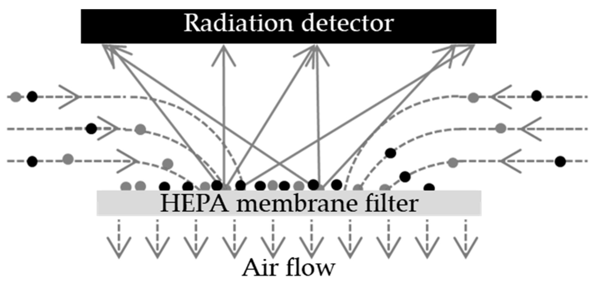
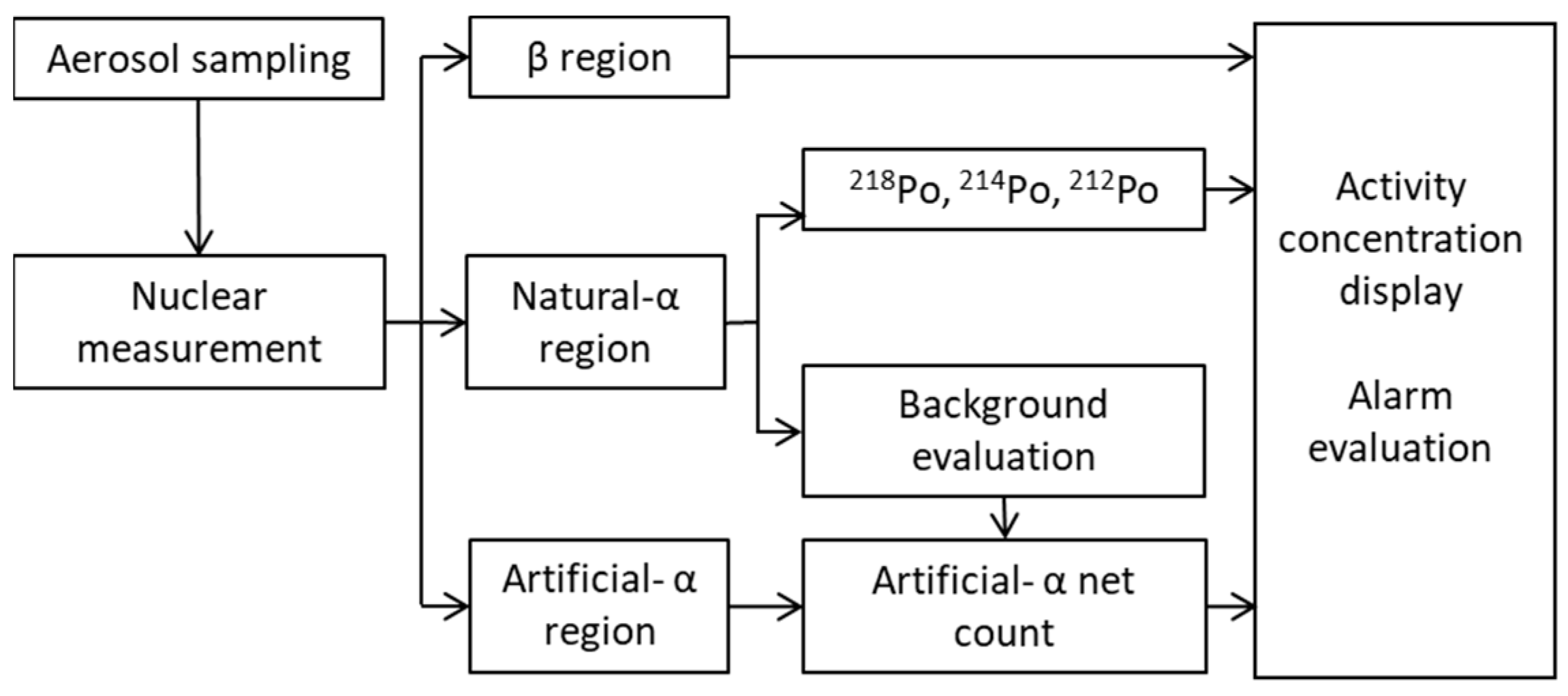
2. Materials and Methods

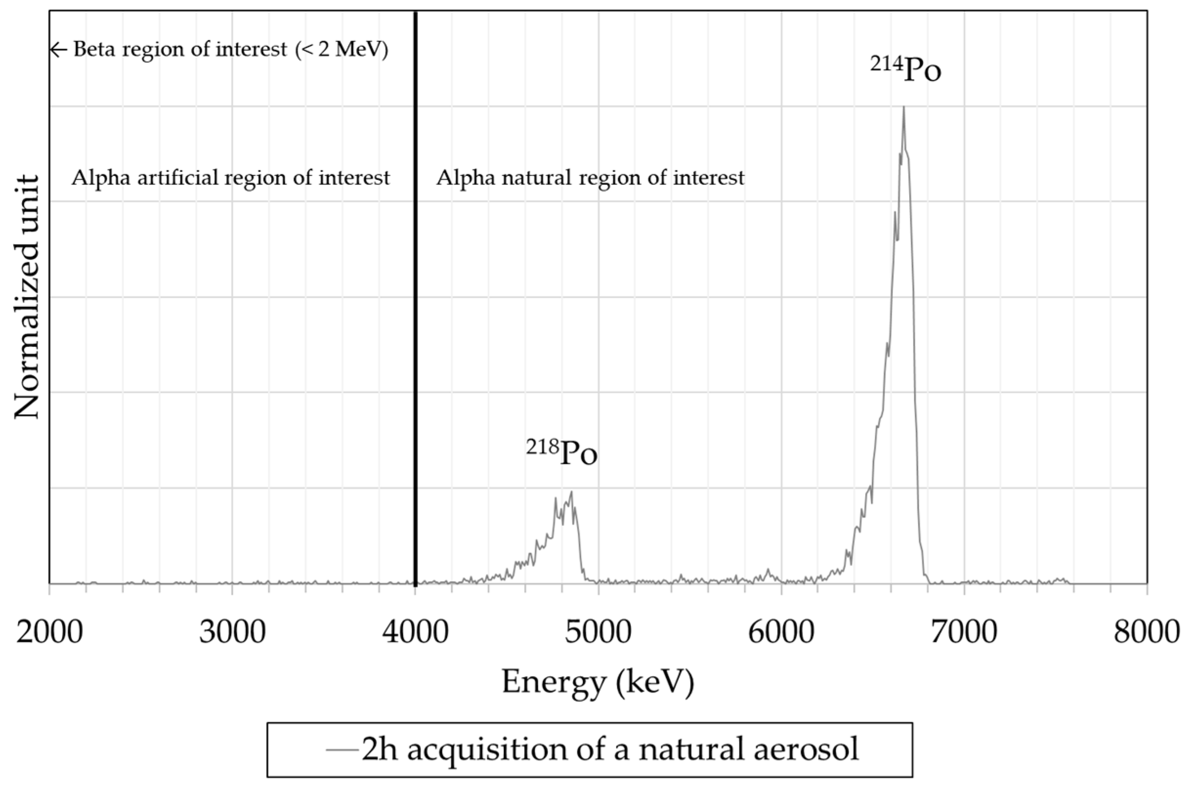
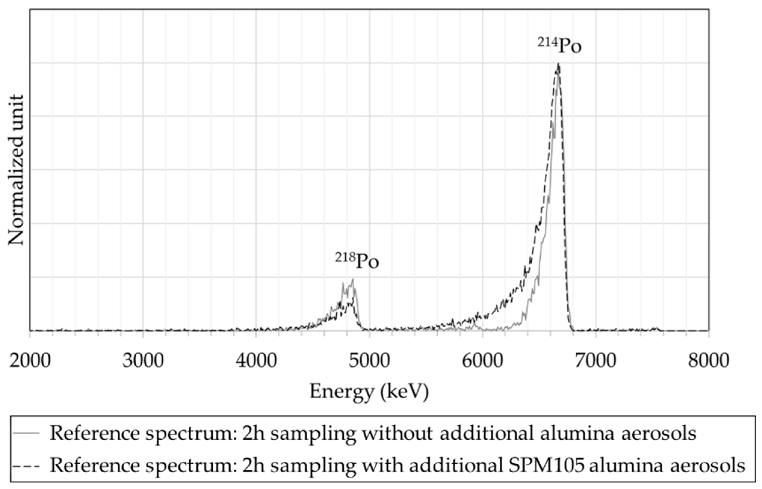
2.1. Reference Experiments

In this paper, we will focus on two experiment results previously obtained on a CAM [8] on the ICARE testing bench [27,28].
A test consists of observing the behaviour of a CAM in a stable atmosphere of 222Rn and daughters that experiences sudden variations in coarse aerosol granulometry. The process is the following:
  • The CAM samples a stable atmosphere of 222Rn and daughters for 2 h;
  • A burst of non-radioactive aerosol is generated;
  • The CAM continues to sample the stable atmosphere of 222Rn and daughters for 2 h.
The CAM’s performance is evaluated in this complex situation where a coarse aerosol deposit suddenly disturbs the nuclear measurement. Notably the spectrum is registered for the 2 h after the coarse aerosol burst (point n° 3).
The reference spectrum, as shown in Figure 4, is subjected to any coarse aerosol deposit. It consists of 2 h of natural aerosol sampling. This natural aerosol, as produced in the ICARE test bench, is composed of a 0.2 µm median diameter aerosol that contains one of the radon daughters. The other of the radon daughters is not attached to the aerosol and is “free” in the air. On the sampling filter, as we focus on the alpha part of the spectrum, we measure only the polonium 218 and 214.
The second reference spectrum has undergone a coarse aerosol. The CAM samples an aerosol of SPM105 alumina powder up to 7.5 mg/m3 in less than 2 min. The sampled aerosol has a diameter of 5.7 µm (non-radioactive) aerosol and is up to 1.4 mg on the filter. The natural (radioactive) aerosol atmosphere is still sampled for 2 h. The spectrum is thus the result of the interaction between the alpha radiations coming from the natural aerosol and the deposited alumina particles. One can notice the variation in the left tail, which is highly noticeable on the 214Po peak.

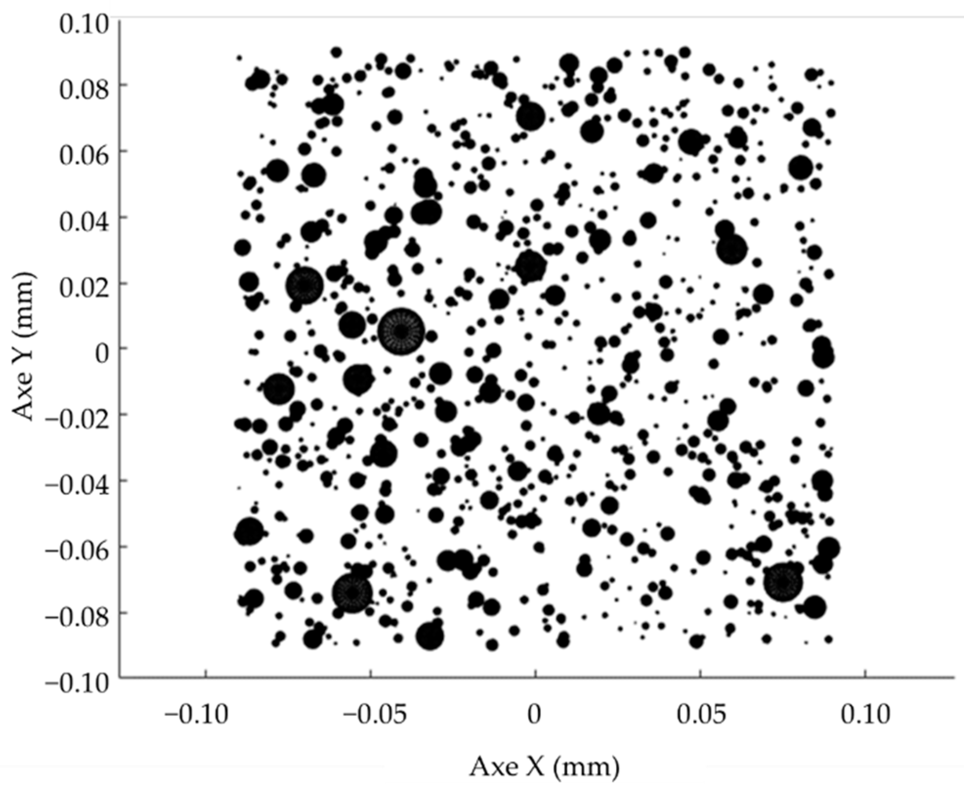
2.2. Particle Deposits

To represent particles depositing on the monitor filter surface, we compare two approaches: atomic mix approximation and brute force.
The heterogeneous material is represented as a mix of all its individual materials with an equivalent density. For the alumina particles used during the experiments, the density of a deposit is linked to the packing porosity that has been defined by Yu [29]:
ϵ ( d ev ) = 0.567 + ( 1 0.567 ) e 0.446 d ev 0.749
with
  • ε, the packing porosity;
  • dev, the median diameter in equivalent volume of the particles.
  • Then, the equivalent density can be calculated as follows:
ρ eq = ρ ( Al 2 O 3 ) ( 1 ϵ ) + ρ ( Air ) ϵ
with
  • ρeq, the equivalent density;
  • ρ(Al2O3), the alumina density, 3.97 g/cm3;
  • ρ(Air), the air density, 1.21 mg/cm3.
We consider the aerosol deposit layer as a cylinder with a diameter equal to that of the filter. The height of this cylinder is then driven by the deposited mass and the defined equivalent density.
To be closer to a real deposit, we developed a spheres stacks approach. The aerosol deposit is represented by an ensemble of spheres, log-normalized distributed in diameter and uniformly distributed on a disc (the filter) along the X and Y axes. The height (Z axis) of each particle is then adjusted so that it does not overlap any other particle. This algorithm determines all the positions for all the particles and serializes these data in a file. However, this algorithm is in O(n2), which is much more time consuming than the layer approach. The calculation presented in Figure 5 (3.5 × 10⁶ particles) was executed in 8 h on an i5-7200U, a duration that remains acceptable. The file that saves all sphere positions and diameters for the transfer to Geant4 is 0.2 Go. Figure 5 enhances a log-normal spherical particle distribution centred on a 100 × 100 µm square on the simulated filter.
This approach has two advantages:
  • The distribution is computed according to a dedicated aerosol model and then integrated in the nuclear simulation tool;
  • Each particle position and diameter are known and can be used as a starting point for a radiation.
Thus, the interaction between the different sizes of aerosol can be challenged, according to a correction particle distribution representation and the nuclear simulation results.

2.3. Simulation of Radiation Transport and Interactions in Matter

The geometry, i.e., the physical representation of the object in Geant4, chosen for the simulations is first based on an ABPM203M [30] by Mirion Technologies, a mobile α-β particulate monitor that uses a silicon semiconductor detector (PIPS [31]). This CAM has been used in previous experiments [8]. This monitor is equipped with a membranous filter of type FSLW (polytetrafluoroethylene membrane from Merck Millipore); thus, the aerosols are sampled on its surface. Figure 6 presents the monitor sampling and detection zones as defined in Geant4, and notably the radial fins specific to the ABPM.
Based on this representation, we simulated 200 000 alpha radiations. They are uniformly distributed on the filter and their energy momenta are isotropic, with half at 6.0 MeV (214Po) and half at 7.7 MeV (218Po). We then adjusted the height of the resulting peaks to match the height of the reference spectrum (Figure 4), an activity calibration. Figure 7 represents both spectra which validate the code: the R2 for the comparison is up to 99.5%, which validates the geometry implementation of the CAM in Geant4.

2.4. Radioactivity Distribution

Radioactivity (i.e., alpha starting points) may be distributed in a variety of ways in the geometry. In the layer approach, it is assumed to be homogeneously distributed within the layer.
In the spheres stacks approach, it is assumed that all the particles have the same probability of being marked by radioactivity. Indeed, in natural radioactivity, 222Rn daughters, as used for the experiments, are carried by fine and ultra-fine particles in size ranges of 100–300 nm (attached fraction) and 0.5–5 nm (free fraction), respectively. In the Kanaoka representation [32], these radioactive aerosols tend to be distributed homogeneously on the surface of the coarse aerosol because the mechanism seems mainly diffusive, as the Stokes and Peclet numbers highlight for both size ranges (Table 1). Thus, as a worst-case scenario, we consider the radioactive nano-aerosol localized uniformly around the coarse aerosol.

3. Results and Discussion

For the reference spectrum for which the measurement is impacted by the alumina particles (Figure 4), the calculated packing porosity is 74% and the equivalent density is 1.03 g/cm3.
Figure 8 presents the comparison figure. One can notice a significant shift to the low-energy part of the simulated spectrum; this approach cannot represent an aerosol deposit. Equation 1 may not be valid here because there are not enough particles to constitute a cake on the filter. Indeed, the presented experiment result involves 3.5 × 10⁶ particles that cover roughly 4% (projected surface) of the filter surface (491 mm2).
Finally, Figure 9 presents the comparison between the measured spectrum and two simulated spectra. The latter consider two radiation sources: the filter and the coarse aerosol. By normalizing the peaks to the maximum, the measured spectrum (the solid grey line) is framed by the two simulations: those with α on the filter and those with α on the whole spheres. It thus becomes possible to correctly represent the experimental spectrum influenced by aerosol deposits.
The simulation results correctly frame the experimental measurement. However, these results were obtained under a few hypotheses:
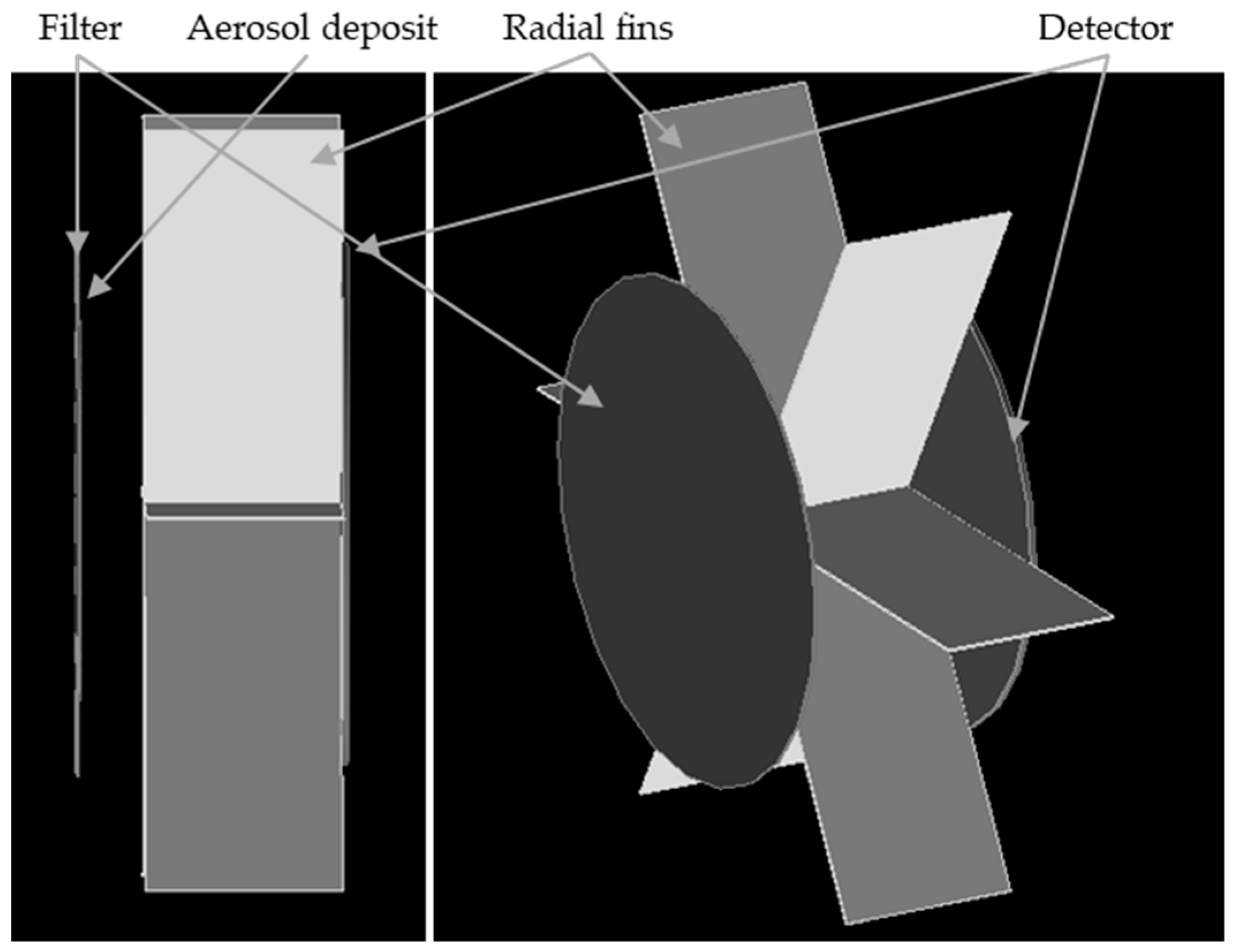
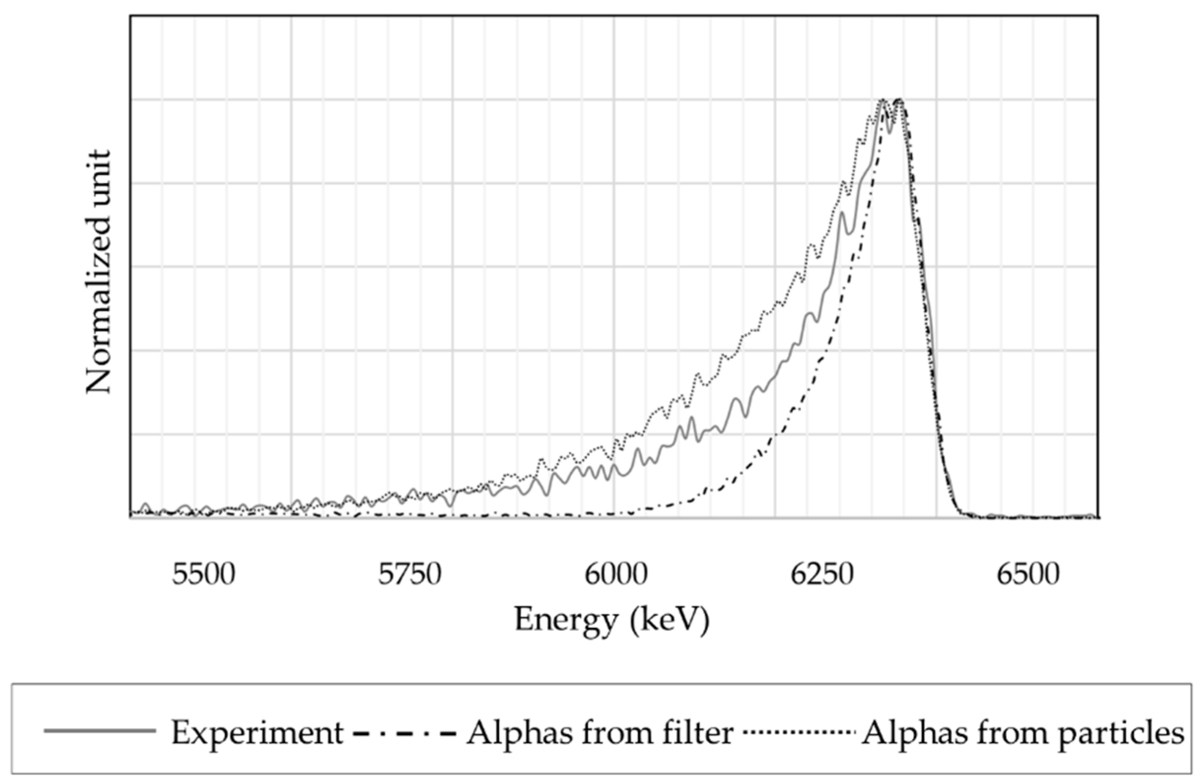
  • The measure is the sum of two effects:
    • Some alphas come from the filter through the deposit;
    • Some alphas come from the aerosol deposit.
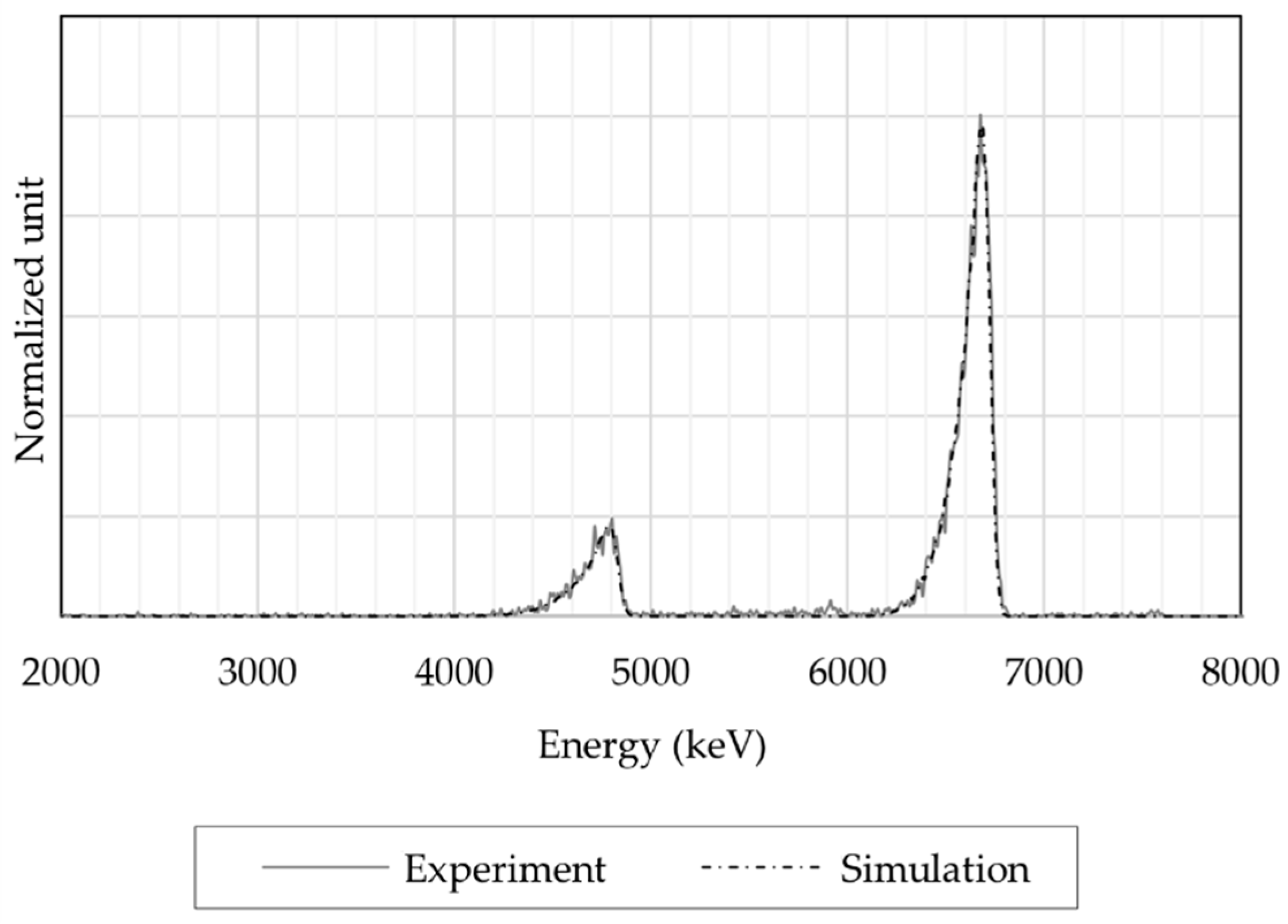
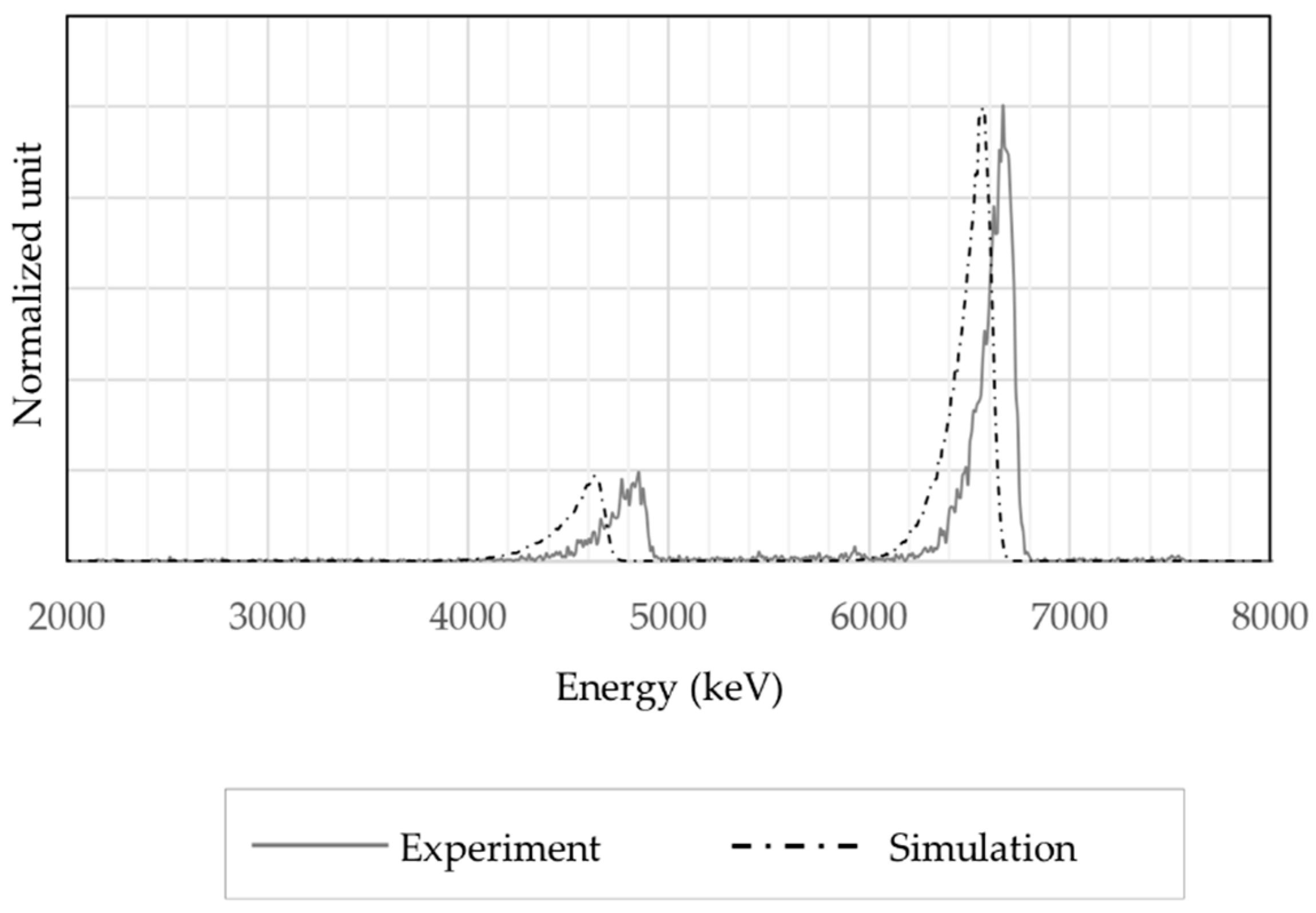
  • The radioactivity is homogeneously distributed on the aerosol surface;
  • The coarse aerosol deposit is made of spherical particles.
These hypotheses seem acceptable. Though, the best fit of the experimental reference as a sum of the two simulations is 50% of the “alphas from filter” plus 50% of “alphas from particles”, with an R2 of 98.9%. This suggests that 50% of the radioactivity comes from the aerosol deposit, despite it representing 13% of the accessible surface compared to the 491 mm2 of the filter. This highlights the necessity to look further in aerosol modelling with various sizes interacting with each other. The method described in this paper, which uses aerosol deposit models and nuclear simulations running together, grants convergence toward a fine understanding of the interactions of multiple aerosol size ranges and the impact of these interactions on the nuclear measurement. This is necessary to study the behaviour of CAM that faces aerosol size and concentration variation. As a corollary, nuclear measurement will be useful to understand an aerosol deposit.

4. Conclusions

An aerosol deposit has been represented in a Monte Carlo simulation using Geant4. Two approaches have been followed. The “atomic mix approximation” to represent a complex material is not appropriate for an aerosol deposit. It cannot handle a mix material composed of localized heavy absorbers.
The brute-force method to represent the aerosol deposit with a stack of spheres has been developed and successfully used here. This approach demonstrates the possibility to generate an aerosol deposit model and then add it to a nuclear simulation, thanks to the sphere representations that are known in both software. The computation time for the brute force method is acceptable for the deposit we considered, and the file transfer from aerosol model to Geant4 is light enough.
The presented result also highlights the necessity to look further in the aerosol modulization. The correct distribution of ultra-fine aerosols, and thus radioactivity, in the deposit has been considered uniform and homogeneous. The current aerosol deposit model cannot handle physical processes, so other models have to be investigated, such as DALEC, an IRSN code that aims to create a physically credible digital deposit of spherical particles that are polydisperse according to a log-normal, and entrained by the air at a constant velocity [36]. It notably considers the Brownian movement and the drag force.
These kinds of methods, which run together the latest advances in aerosol deposit model and nuclear simulations, open the road to progress in the understanding of interactions between multiple aerosol size ranges in high velocities, as well as their impact on measurement. As a corollary, nuclear measurement will be useful to understand aerosol deposits.
This research will make it possible to progress on the remaining questions concerning the behaviour of monitors in delicate situations and more generally on the filtration of aerosols by combining multiple theories, simulations, and experimentations in both aerosol science and nuclear physics.

Author Contributions

The presented models and results have been developed during the internships of W.S., K.A. and D.M. at IRSN under the supervision of G.D. All authors have read and agreed to the published version of the manuscript.

Funding

This research received no external funding.

Data Availability Statement

Data available in a publicly accessible repository that does not issue DOIs. This data can be found here: https://www.theses.fr/2020UPASP055 (accessed on 10 November 2022).

Conflicts of Interest

The authors declare no conflict of interest.

References

  1. Geryes, T. Etude Expérimentale et Numérique de La Dégradation de La Mesure Nucléaire d’aérosols Radioactifs Prélevés Avec Des Filtres de Surveillance. Ph.D. Thesis, Université Paris Est, Paris, France, 2009. [Google Scholar]
  2. Bé, M.-M.; Chisté, V.; Dulieu, C.; Chechev, V.; Kuzmenko, N.; Galán, M.; Pearce, A.; Huang, X. Table of Radionuclides (Vol. 4–A = 133 to 252); BIPM: Sèvres, France, 2008; Volume 4, ISBN 9282222047. [Google Scholar]
  3. Hayes, R.B. False CAM Alarms from Radon Fluctuations. Radiat. Saf. J. 2003, 85, S81–S84. [Google Scholar] [CrossRef] [PubMed]
  4. Li, H.; Jia, M.; Wang, K. Critical Level Setting of Continuous Air Monitor. Radiat. Prot. Dosim. 2013, 154, 391–395. [Google Scholar] [CrossRef] [PubMed]
  5. Justus, A. Technical Details of the Sigma Factor Alarm Method within Alpha CAMs. Health Phys. 2021, 120, 442–453. [Google Scholar] [CrossRef] [PubMed]
  6. Klett, A.; Reuter, W.; De Mey, L. Dynamic Calibration of an Aerosol Monitor with Natural and Artificial Alpha-Emitters. IEEE Trans. Nucl. Sci. 1997, 44, 804–805. [Google Scholar] [CrossRef]
  7. Hoarau, G.; Dougniaux, G.; Gensdarmes, F.; Ranchoux, G.; Cassette, P. Impact of the Coarse Indoor Non-Radioactive Aerosols on the Background Radon Progenies Compensation of Continuous Air Monitor. Health Phys. 2022, 122, 563–574. [Google Scholar] [CrossRef] [PubMed]
  8. Hoarau, G. Étude de La Limite de Détection et Des Fausses Alarmes Émises Par Les Moniteurs de Mesure de La Contamination Radioactive Atmosphérique Dans Les Chantiers de Démantèlement. Ph.D. Thesis, Université Paris-Saclay, Paris, France, 2020. [Google Scholar]
  9. Hoarau, G.; Dougniaux, G.; Gensdarmes, F. Procédé et Système de Surveillance En Continu de La Contamination Radioactive Atmosphérique. Patent FR 2005284. Available online: https://patents.google.com/patent/EP0090680A1/fr (accessed on 10 November 2022).
  10. Kulkarni, P.; Baron, P.A.; Willeke, K. Aerosol Measurement: Principles, Techniques and Applications, 3rd ed.; Wiley: Hoboken, NJ, USA, 2011; ISBN 978-0-470-38741. [Google Scholar]
  11. Dougniaux, G.; Monsanglant-Louvet, C.; Teppe, A.-L.; Marcillaud, B.; Dieux Lestaevel, B.; Gensdarmes, F.; Michielsen, N.; Bondiguel, S.; Boussetta, B.; Quentel, G. Results from a Measurement Campaign in Dismantling Nuclear Sites: A Study of the False Alarms Emitted by CAM. In Proceedings of the European Aerosol Conference 2016, Tours, France, 4–9 September 2016. [Google Scholar]
  12. Charuau, J.; Pescayre, G.; Prigent, R. Moniteur Individuel de La Contamination Atmosphérique Alpha (Type Monica α). Radioprotection 1984, 19, 1–13. [Google Scholar] [CrossRef] [Green Version]
  13. Abou-Khalil, R. Caractéristique de La Charge Électrique d’un Aérosol Radioactif Naturel. Ph.D. Theses, Université Louis Pasteur, Strasbourg, France, 2008. [Google Scholar]
  14. Raabe, O.G. Concerning the Interactions that Occur between Radon Decay Products and Aerosols. Health Phys. 1969, 17, 177–185. [Google Scholar] [CrossRef] [PubMed]
  15. Bricard, J.; Cabane, M.; Madelaine, G. Formation of Atmospheric Ultrafine Particles and Ions from Trace Gases. J. Colloid Interface Sci. 1977, 58, 113–124. [Google Scholar] [CrossRef]
  16. Porstendörfer, J.; Pagelkopf, P.; Gründel, M. Fraction of the Positive 218Po and 214Pb Clusters in Indoor Air. Radiat. Prot. Dosim. 2005, 113, 342–351. [Google Scholar] [CrossRef] [PubMed]
  17. Adams, M.L.; Larsen, E.W.; Pomraning, G.C. Benchmark Results for Particle Transport in a Binary Markov Statistical Medium. J. Quant. Spectrosc. Radiat. Transf. 1989, 42, 253–266. [Google Scholar] [CrossRef]
  18. Pomraning, G.C. Linear Kinetic Theory and Particle Transport in Stochastic Mixtures; World Scientific Publishing Company: Singapore, 1991; Volume 7. [Google Scholar] [CrossRef]
  19. Reinert, D.R.; Schneider, E.A.; Biegalski, S.R.F. Investigation of Stochastic Radiation Transport Methods in Binary Random Heterogeneous Mixtures. Nucl. Sci. Eng. 2010, 166, 167–174. [Google Scholar] [CrossRef]
  20. Geryes, T.; Monsanglant-Louvet, C. Determination of Correction Factors for Alpha Activity Measurements in the Environment (Conditions of High Dust Loadings). Radiat. Prot. Dosim. 2011, 144, 659–662. [Google Scholar] [CrossRef]
  21. Larmier, C.; Lam, A.; Brantley, P.; Malvagi, F.; Palmer, T.; Zoia, A. Monte Carlo Chord Length Sampling for D-Dimensional Markov Binary Mixtures. J. Quant. Spectrosc. Radiat. Transf. 2018, 204, 256–271. [Google Scholar] [CrossRef] [Green Version]
  22. MacFadden, N.J.L.; Knaian, A.N. Efficient Modeling of Particle Transport through Aerosols in Geant4. Comput. Phys. Commun. 2022, 278, 108383. [Google Scholar] [CrossRef]
  23. Agostinelli, S.; Allison, J.; Amako, K.; Apostolakis, J.; Araujo, H.; Arce, P.; Asai, M.; Axen, D.; Banerjee, S.; Barrand, G.; et al. GEANT4—A Simulation Toolkit. Nucl. Instrum. Methods Phys. Res. Sect. A Accel. Spectrom. Detect. Assoc. Equip. 2003, 506, 250–303. [Google Scholar] [CrossRef] [Green Version]
  24. Allison, J.; Amako, K.; Apostolakis, J.; Arce, P.; Asai, M.; Aso, T.; Bagli, E.; Bagulya, A.; Banerjee, S.; Barrand, G.; et al. Recent Developments in GEANT4. Nucl. Instrum. Methods Phys. Res. Sect. A Accel. Spectrom. Detect. Assoc. Equip. 2016, 835, 186–225. [Google Scholar] [CrossRef]
  25. Siiskonen, T.; Pöllänen, R. Advanced Simulation Code for Alpha Spectrometry. Nucl. Instrum. Methods Phys. Res. Sect. A Accel. Spectrom. Detect. Assoc. Equip. 2005, 550, 425–434. [Google Scholar] [CrossRef] [Green Version]
  26. Siiskonen, T.; Pöllänen, R.; Karhunen, T. A Versatile Simulation Code for Alpha Spectrometry: Development of the Graphical User Interface and Applications. ESARDA Bull. 2008, 40, 26–30. [Google Scholar]
  27. Ammerich, M. Réalisation d’une Installation d’étalonnade de Moniteurs de Contamination Atmosphérique à l’aide d’aérosols Radioactifs Calibrés (ICARE); CEA Report n°CEA-R-5484; CEA Fontenay-aux-Roses: Fontenay-aux-Roses, France, 1989. [Google Scholar]
  28. Zettwoog, P. ICARE Radon Calibration Device. J. Res. Natl. Inst. Stand. Technol. 1990, 95, 147–153. [Google Scholar] [CrossRef] [PubMed]
  29. Yu, A.B.; Zou, Z.P. Porosity Calculation of Particle Mixtures: An Overview. In Proceedings of the TMS Annual Meeting, Orlando, FL, USA, 9–13 February 1997. [Google Scholar]
  30. Mirion Technology ABPM 203M Mobile Alpha Beta Particulate Monitor. Available online: https://www.mirion.com/products/abpm-203m-mobile-alpha-beta-particulate-monitor (accessed on 15 November 2022).
  31. PIPS Detectors. Information Brochure C39313—04/12; Mirion Technologies: Atlanta, GA, USA, 2017. [Google Scholar]
  32. Kanaoka, C. Fine Particle Filtration Technology Using Fiber as Dust Collection Medium. KONA Powder Part. J. 2019, 36, 88–113. [Google Scholar] [CrossRef]
  33. Baron, P.A.; Willeke, K. Aerosol Measurement, Principles Techniques and Applications, 2nd ed.; Wiley: New York, NY, USA, 2001. [Google Scholar]
  34. Willeke, K.; Baron, P.A. Aerosol Measurement; Van Nostrand Reihold: Washington, DC, USA, 1993. [Google Scholar]
  35. Hinds, W.C. Aerosol Technology; John Wiley & Sons: Hoboken, NJ, USA, 1999; ISBN 978-0-582-41483-9. [Google Scholar]
  36. Lecoanet, A.; Bourrous, S. Morphological Parameters Investigation of Deposits Formed on Pleated Filters Using DLA. Separation and Purification Technology, To be Published.
Figure 1. Illustration of the aerosol sampling and measurement of a CAM. The grey circles represent a radioactive aerosol, the black circles a non-radioactive aerosol. Both are sampled and interacts with each other. Dashed arrows represent the air flow and plain arrows the radiations.
Atmosphere 13 02113 g001
Figure 2. Illustration of a CAM radiation measurement. It shows the two regions of interest, one for artificial alpha and one for natural alpha. A third one dedicated to the beta, below 2 MeV, is not highlighted here because it is not relevant.
Atmosphere 13 02113 g002
Figure 3. Illustration of the CAM measurement processes from aerosol sampling to activity concentration display.
Atmosphere 13 02113 g003
Figure 4. The two reference spectra used in the present paper. Grey-dotted line—a 2 h sampling without additional alumina aerosols in the stable atmosphere of radon; black-dashed line—a 2 h sampling with additional SPM105 alumina aerosols (1.4 mg on the filter) in the same atmosphere.
Atmosphere 13 02113 g004
Figure 5. Enhancement of spherical particle distribution on a 100 × 100 µm square in the simulated filter.
Atmosphere 13 02113 g005
Figure 6. Representation of the sampling and detection zones, as defined in Geant4 and based on a Mirion ABPM203M.
Atmosphere 13 02113 g006
Figure 7. Comparison between an experimental spectrum and a simulated one for the two alpha emissions of 218Po and 214Po. Both plots are quite undistinguishable.
Atmosphere 13 02113 g007
Figure 8. Comparison between an experimental spectrum and a simulated one for the two alpha emissions of 218Po and 214Po in the equivalent layer approach.
Atmosphere 13 02113 g008
Figure 9. Comparison between an experimental spectrum and two simulated spectra, centred on the 214Po alpha peak. The alpha-radiation source in the two simulations differs: one comes from the filter, while the other from the coarse particles.
Atmosphere 13 02113 g009
Table 1. Data for Stokes and Peclet numbers calculations (Equations (9-5), (9-8), (9-11) and (9-13) [33]), (Equations (10-5), (10-8), (10-11) and (10-13) [34]), (Equations (9-13)–(9-33) [35]).
ParameterAttached FractionFree Fraction
Temperature293 K
Pressure1013 hPa
Median diameter0.2 µm0.5–5 nm
Particle densityCsCl—4 g/cm3Po/Bi/Pb—10 g/cm3
Sampling velocity1.2 m/s
Diffusion coefficient2 × 10−10 m2/s2 × 10−7 m2/s
Peclet number30 × 10330
Stokes number2 × 10−17 × 10−3
Publisher’s Note: MDPI stays neutral with regard to jurisdictional claims in published maps and institutional affiliations.

