
A Novel Window into Angiogenesis—Intravital Microscopy in the AV-Loop-Model
 , , , , and
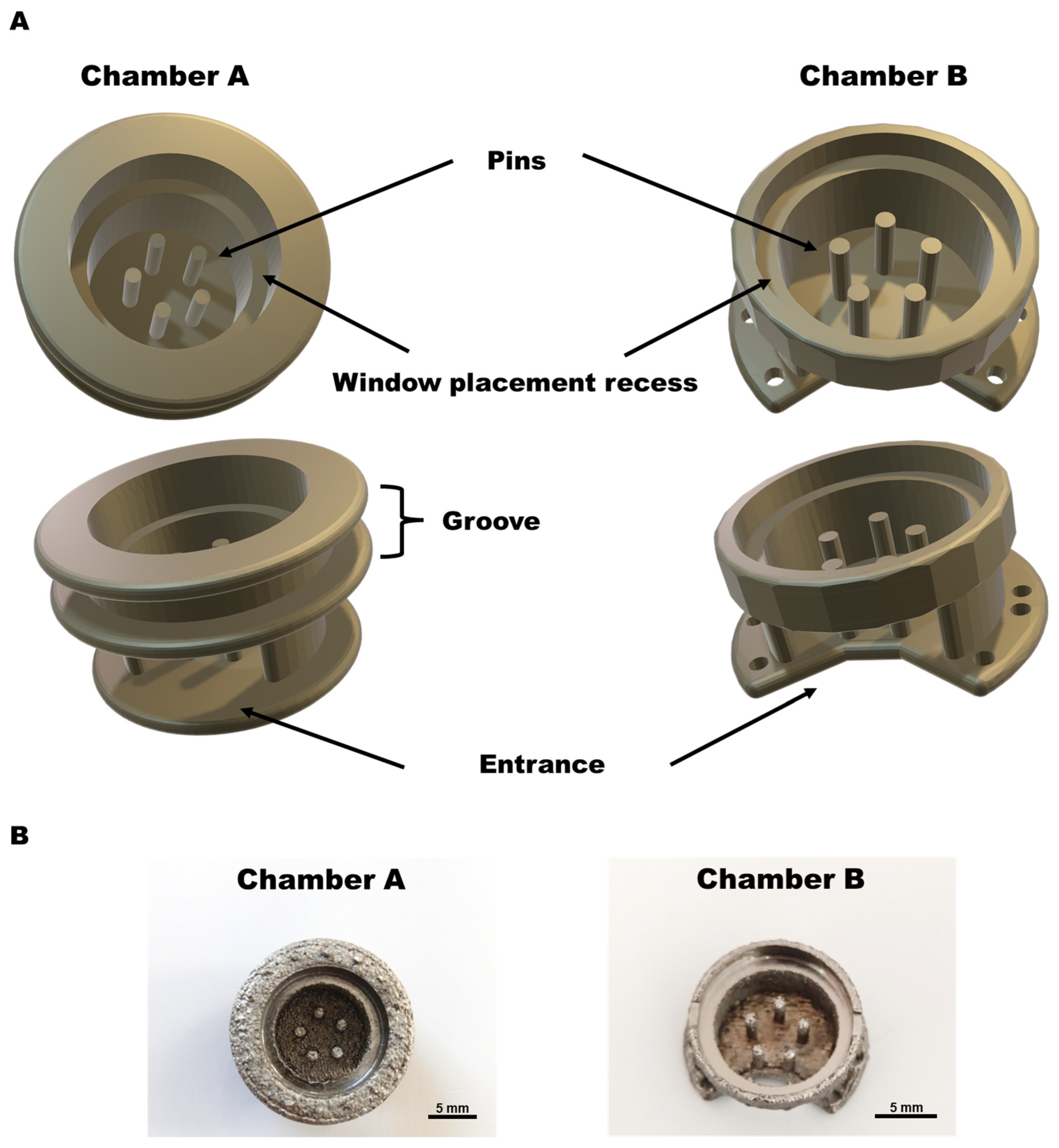
Abstract
:1. Introduction
2. Materials and Methods
2.1. Animals
2.2. Chamber Design
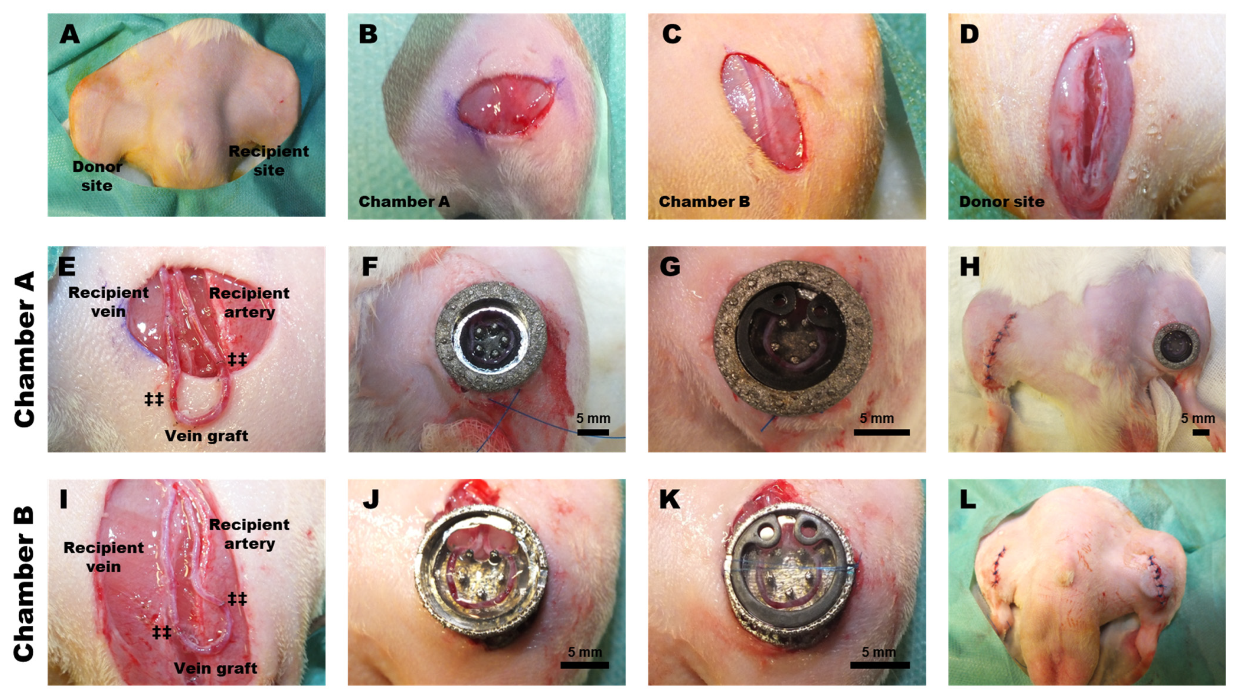
2.3. Surgical Procedure
2.4. Post-Operative Treatment
2.5. Intravital Microscopy
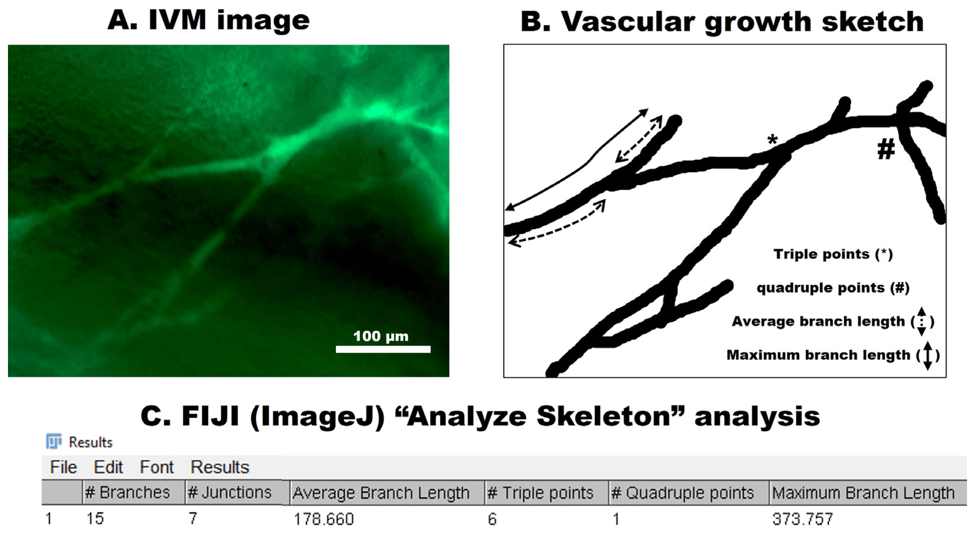
2.6. Microcirculatory Analysis
2.7. Statistical Analysis
3. Results
3.1. Chamber Stability
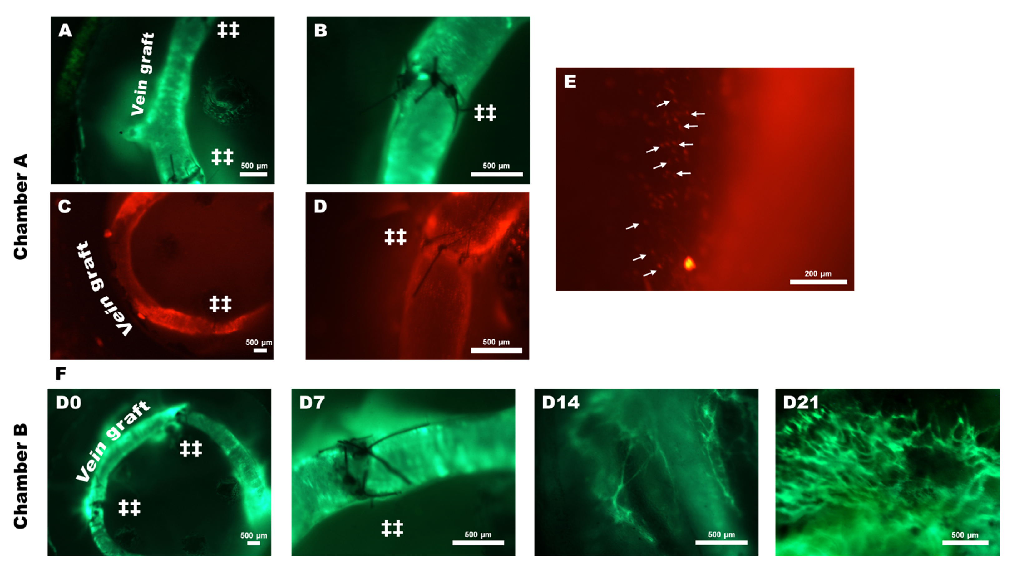
3.2. Intravital Imaging
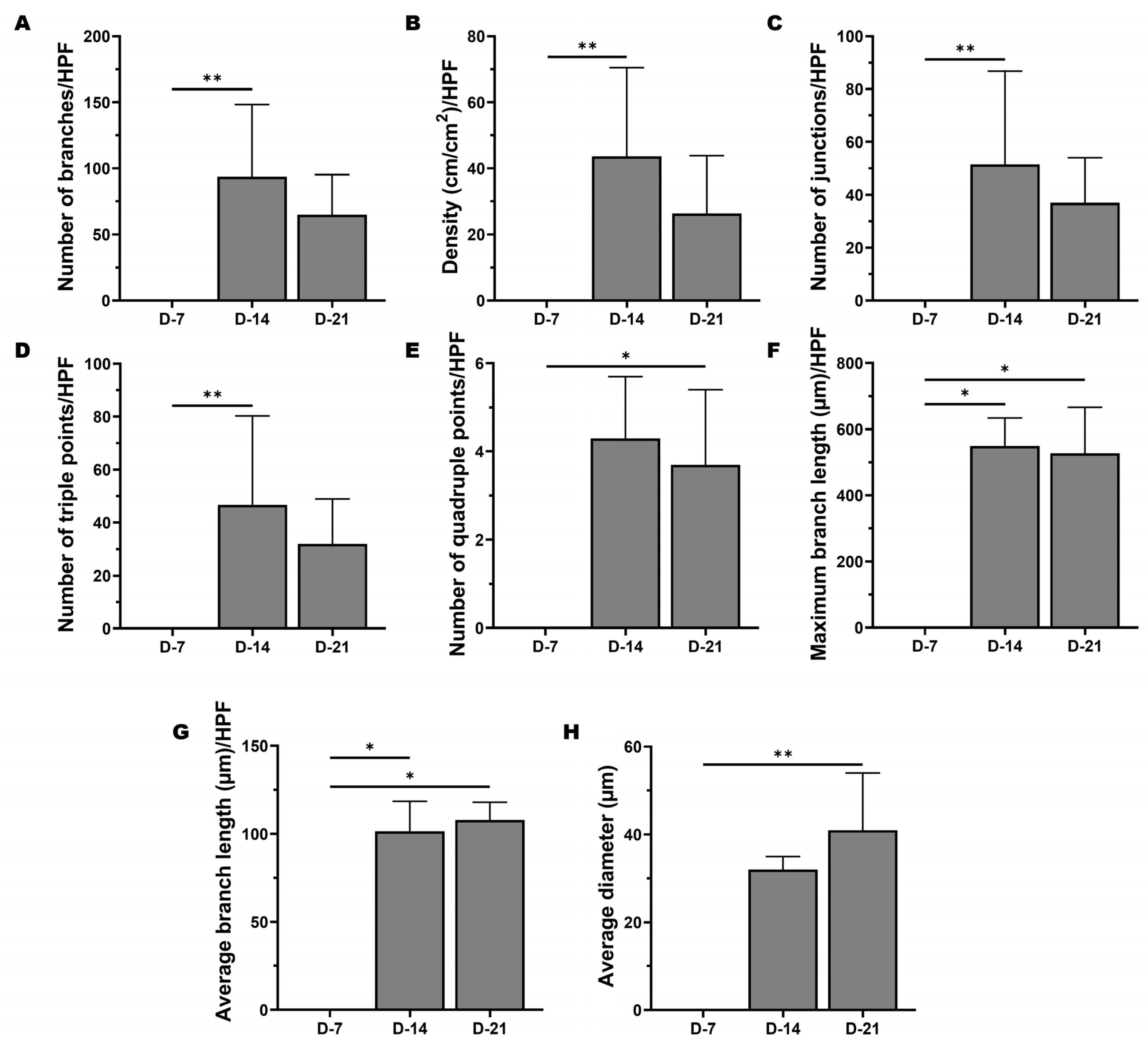
3.3. Intravital Analysis
4. Discussion
5. Conclusions
Supplementary Materials
Author Contributions
Funding
Institutional Review Board Statement
Informed Consent Statement
Data Availability Statement
Conflicts of Interest
References
- Cai, A.; Zheng, Z.-M.; Himmler, M.; Schubert, D.W.; Fuchsluger, T.A.; Weisbach, V.; Horch, R.E.; Arkudas, A. Schwann Cells Promote Myogenic Differentiation of Myoblasts and Adipogenic Mesenchymal Stromal Cells on Poly-ε-Caprolactone-Collagen I-Nanofibers. Cells 2022, 11, 1436. [Google Scholar] [CrossRef] [PubMed]
- Samandari, M.; Quint, J.; Rodríguez-delaRosa, A.; Sinha, I.; Pourquié, O.; Tamayol, A. Bioinks and Bioprinting Strategies for Skeletal Muscle Tissue Engineering. Adv. Mater. 2022, 34, 2105883. [Google Scholar] [CrossRef] [PubMed]
- Cai, A.; Zheng, Z.; Müller-Seubert, W.; Biggemann, J.; Fey, T.; Beier, J.P.; Horch, R.E.; Frieß, B.; Arkudas, A. Microsurgical Transplantation of Pedicled Muscles in an Isolation Chamber—A Novel Approach to Engineering Muscle Constructs via Perfusion-Decellularization. J. Pers. Med. 2022, 12, 442. [Google Scholar] [CrossRef]
- Chang, W.G.; Niklason, L.E. A Short Discourse on Vascular Tissue Engineering. NPJ Regen. Med. 2017, 2, 7. [Google Scholar] [CrossRef] [PubMed]
- Weinzierl, A.; Harder, Y.; Schmauss, D.; Menger, M.D.; Laschke, M.W. Boosting Tissue Vascularization: Nanofat as a Potential Source of Functional Microvessel Segments. Front. Bioeng. Biotechnol. 2022, 10, 820835. [Google Scholar] [CrossRef] [PubMed]
- Müller-Seubert, W.; Ostermaier, P.; Horch, R.E.; Distel, L.; Frey, B.; Cai, A.; Arkudas, A. Intra- and Early Postoperative Evaluation of Malperfused Areas in an Irradiated Random Pattern Skin Flap Model Using Indocyanine Green Angiography and Near-Infrared Reflectance-Based Imaging and Infrared Thermography. J. Pers. Med. 2022, 12, 237. [Google Scholar] [CrossRef]
- Geierlehner, A.; Horch, R.E.; Ludolph, I.; Arkudas, A. Intraoperative Blood Flow Analysis of DIEP vs. Ms-TRAM Flap Breast Reconstruction Combining Transit-Time Flowmetry and Microvascular Indocyanine Green Angiography. J. Pers. Med. 2022, 12, 482. [Google Scholar] [CrossRef]
- Khalil, A.S.; Jaenisch, R.; Mooney, D.J. Engineered Tissues and Strategies to Overcome Challenges in Drug Development. Adv. Drug Deliv. Rev. 2020, 158, 116–139. [Google Scholar] [CrossRef]
- Xu, Y.; Shrestha, N.; Préat, V.; Beloqui, A. An Overview of in Vitro, Ex Vivo and in Vivo Models for Studying the Transport of Drugs across Intestinal Barriers. Adv. Drug Deliv. Rev. 2021, 175, 113795. [Google Scholar] [CrossRef]
- Vaghela, R.; Arkudas, A.; Horch, R.E.; Hessenauer, M. Actually Seeing What Is Going on—Intravital Microscopy in Tissue Engineering. Front. Bioeng. Biotechnol. 2021, 9, 627462. [Google Scholar] [CrossRef]
- Weigand, A.; Beier, J.P.; Arkudas, A.; Al-Abboodi, M.; Polykandriotis, E.; Horch, R.E.; Boos, A.M. The Arteriovenous (AV) Loop in a Small Animal Model to Study Angiogenesis and Vascularized Tissue Engineering. J. Vis. Exp. 2016, 117, 54676. [Google Scholar] [CrossRef] [PubMed]
- Heltmann-Meyer, S.; Steiner, D.; Müller, C.; Schneidereit, D.; Friedrich, O.; Salehi, S.; Engel, F.B.; Arkudas, A.; Horch, R.E. Gelatin Methacryloyl Is a Slow Degrading Material Allowing Vascularization and Long-Term Usein Vivo. Biomed. Mater. 2021, 16, 065004. [Google Scholar] [CrossRef]
- Dawson, C.A.; Mueller, S.N.; Lindeman, G.J.; Rios, A.C.; Visvader, J.E. Intravital Microscopy of Dynamic Single-Cell Behavior in Mouse Mammary Tissue. Nat. Protoc. 2021, 16, 1907–1935. [Google Scholar] [CrossRef]
- Kengelbach-Weigand, A.; Thielen, C.; Bäuerle, T.; Götzl, R.; Gerber, T.; Körner, C.; Beier, J.P.; Horch, R.E.; Boos, A.M. Personalized Medicine for Reconstruction of Critical-Size Bone Defects—A Translational Approach with Customizable Vascularized Bone Tissue. NPJ Regen. Med. 2021, 6, 49. [Google Scholar] [CrossRef] [PubMed]
- Weigand, A.; Horch, R.E.; Boos, A.M.; Beier, J.P.; Arkudas, A. The Arteriovenous Loop: Engineering of Axially Vascularized Tissue. Eur. Surg. Res. 2018, 59, 286–299. [Google Scholar] [CrossRef] [Green Version]
- Marchesini, A.; Senesi, L.; De Francesco, F.; Pangrazi, P.P.; Campodonico, A.; Politano, R.; Riccio, M. Efficacy of the Arteriovenous Loop for Free Flap Reconstruction in Patients with Complex Limb Trauma: Case Series and Literature Review. Medicina 2020, 56, 632. [Google Scholar] [CrossRef]
- Knackstedt, R.; Aliotta, R.; Gatherwright, J.; Djohan, R.; Gastman, B.; Schwarz, G.; Hendrickson, M.; Gurunluoglu, R. Single-Stage versus Two-Stage Arteriovenous Loop Microsurgical Reconstruction: A Meta-Analysis of the Literature. Microsurgery 2018, 38, 706–717. [Google Scholar] [CrossRef] [PubMed]
- Hessenauer, M.; Vaghela, R.; Körner, C.; von Hörsten, S.; Pobel, C.; Gage, D.; Müller, C.; Salehi, S.; Horch, R.E.; Arkudas, A. Watching the Vessels Grow: Establishment of Intravital Microscopy in the Arteriovenous Loop Rat Model. Tissue Eng. Part C Methods 2021, 27, 357–365. [Google Scholar] [CrossRef]
- Vaghela, R.; Arkudas, A.; Gage, D.; Körner, C.; von Hörsten, S.; Salehi, S.; Horch, R.E.; Hessenauer, M. Microvascular Development in the Rat Arteriovenous Loop Model in Vivo-A Step by Step Intravital Microscopy Analysis. J. Biomed. Mater. Res. A 2022, 110, 1551–1563. [Google Scholar] [CrossRef]
- Narushima, M.; Koshima, I.; Mihara, M.; Uchida, G.; Gonda, K. Intravascular Stenting (IVaS) for Safe and Precise Supermicrosurgery. Ann. Plast. Surg. 2008, 60, 41–44. [Google Scholar] [CrossRef]
- Wong, R.; Donno, R.; Leon-Valdivieso, C.Y.; Roostalu, U.; Derby, B.; Tirelli, N.; Wong, J.K. Angiogenesis and Tissue Formation Driven by an Arteriovenous Loop in the Mouse. Sci. Rep. 2019, 9, 10478. [Google Scholar] [CrossRef] [PubMed] [Green Version]
- An, R.; Strissel, P.L.; Al-Abboodi, M.; Robering, J.W.; Supachai, R.; Eckstein, M.; Peddi, A.; Hauck, T.; Bäuerle, T.; Boccaccini, A.R.; et al. An Innovative Arteriovenous (AV) Loop Breast Cancer Model Tailored for Cancer Research. Bioengineering 2022, 9, 280. [Google Scholar] [CrossRef]
- Aslan-Horch, E.C.; Horch, R.E.; Arkudas, A.; Müller-Seubert, W.; Ludolph, I. Effects of Different Pressure Levels in Topical Negative Pressure Application—Analysis of Perfusion Parameters in a Clinical Skin Model Using Multimodal Imaging Techniques. J. Clin. Med. 2022, 11, 5133. [Google Scholar] [CrossRef] [PubMed]
- Koch, S.E.; de Kort, B.J.; Holshuijsen, N.; Brouwer, H.F.M.; van der Valk, D.C.; Dankers, P.Y.W.; van Luijk, J.A.K.R.; Hooijmans, C.R.; de Vries, R.B.M.; Bouten, C.V.C.; et al. Animal Studies for the Evaluation of in Situ Tissue-Engineered Vascular Grafts—A Systematic Review, Evidence Map, and Meta-Analysis. NPJ Regen. Med. 2022, 7, 17. [Google Scholar] [CrossRef] [PubMed]
- Germain, R.N.; Miller, M.J.; Dustin, M.L.; Nussenzweig, M.C. Dynamic Imaging of the Immune System: Progress, Pitfalls and Promise. Nat. Rev. Immunol. 2006, 6, 497–507. [Google Scholar] [CrossRef]
- Entenberg, D.; Oktay, M.H.; Condeelis, J.S. Intravital Imaging to Study Cancer Progression and Metastasis. Nat. Rev. Cancer 2023, 23, 25–42. [Google Scholar] [CrossRef]
- Horton, N.G.; Wang, K.; Kobat, D.; Clark, C.G.; Wise, F.W.; Schaffer, C.B.; Xu, C. In Vivo Three-Photon Microscopy of Subcortical Structures within an Intact Mouse Brain. Nat. Photonics 2013, 7, 205–209. [Google Scholar] [CrossRef]
- Wang, F.; Ren, F.; Ma, Z.; Qu, L.; Gourgues, R.; Xu, C.; Baghdasaryan, A.; Li, J.; Zadeh, I.E.; Los, J.W.N.; et al. In Vivo Non-Invasive Confocal Fluorescence Imaging beyond 1,700 Nm Using Superconducting Nanowire Single-Photon Detectors. Nat. Nanotechnol. 2022, 17, 653–660. [Google Scholar] [CrossRef]
- Perrin, L.; Bayarmagnai, B.; Gligorijevic, B. Frontiers in Intravital Multiphoton Microscopy of Cancer. Cancer Rep. 2019, 3, e1192. [Google Scholar] [CrossRef]
- Hessenauer, M.E.T.; Lauber, K.; Zuchtriegel, G.; Uhl, B.; Hussain, T.; Canis, M.; Strieth, S.; Berghaus, A.; Reichel, C.A. Vitronectin Promotes the Vascularization of Porous Polyethylene Biomaterials. Acta Biomater. 2018, 82, 24–33. [Google Scholar] [CrossRef]
- Gniesmer, S.; Brehm, R.; Hoffmann, A.; de Cassan, D.; Menzel, H.; Hoheisel, A.L.; Glasmacher, B.; Willbold, E.; Reifenrath, J.; Ludwig, N.; et al. Vascularization and Biocompatibility of Poly(ε-Caprolactone) Fiber Mats for Rotator Cuff Tear Repair. PLoS ONE 2020, 15, e0227563. [Google Scholar] [CrossRef] [PubMed] [Green Version]
- Chamma, E.; Daradich, A.; Côté, D.; Yun, S.-H. Intravital Microscopy. In Pathobiology of Human Disease; McManus, L.M., Mitchell, R.N., Eds.; Academic Press: San Diego, CA, USA, 2014; pp. 3959–3972. ISBN 978-0-12-386457-4. [Google Scholar]
- Shirshin, E.A.; Yakimov, B.P.; Darvin, M.E.; Omelyanenko, N.P.; Rodionov, S.A.; Gurfinkel, Y.I.; Lademann, J.; Fadeev, V.V.; Priezzhev, A.V. Label-Free Multiphoton Microscopy: The Origin of Fluorophores and Capabilities for Analyzing Biochemical Processes. Biochem. Mosc. 2019, 84, 69–88. [Google Scholar] [CrossRef] [PubMed]
- Tanaka, Y.; Sung, K.-C.; Tsutsumi, A.; Ohba, S.; Ueda, K.; Morrison, W.A. Tissue Engineering Skin Flaps: Which Vascular Carrier, Arteriovenous Shunt Loop or Arteriovenous Bundle, Has More Potential for Angiogenesis and Tissue Generation? Plast. Reconstr. Surg. 2003, 112, 1636–1644. [Google Scholar] [CrossRef] [PubMed]
- Dong, Q.; Shang, H.; Wu, W.; Chen, F.; Zhang, J.; Guo, J.; Mao, T. Prefabrication of Axial Vascularized Tissue Engineering Coral Bone by an Arteriovenous Loop: A Better Model. Mater. Sci. Eng. C Mater. Biol. Appl. 2012, 32, 1536–1541. [Google Scholar] [CrossRef]
- Wu, X.; Wang, Q.; Kang, N.; Wu, J.; Gu, C.; Bi, J.; Lv, T.; Xie, F.; Hu, J.; Liu, X.; et al. The Effects of Different Vascular Carrier Patterns on the Angiogenesis and Osteogenesis of BMSC-TCP-Based Tissue-Engineered Bone in Beagle Dogs. J. Tissue Eng. Regen. Med. 2017, 11, 542–552. [Google Scholar] [CrossRef]
- Polykandriotis, E.; Arkudas, A.; Euler, S.; Beier, J.P.; Horch, R.E.; Kneser, U. Prävaskularisationsstrategien im Tissue Engineering. Handchir. Mikrochir. Plast. Chir. 2006, 38, 217–223. [Google Scholar] [CrossRef]
- Steiner, D.; Lang, G.; Fischer, L.; Winkler, S.; Fey, T.; Greil, P.; Scheibel, T.; Horch, R.E.; Arkudas, A. Intrinsic Vascularization of Recombinant EADF4(C16) Spider Silk Matrices in the Arteriovenous Loop Model. Tissue Eng. Part A 2019, 25, 1504–1513. [Google Scholar] [CrossRef]
- Buehrer, G.; Balzer, A.; Arnold, I.; Beier, J.P.; Koerner, C.; Bleiziffer, O.; Brandl, A.; Weis, C.; Horch, R.E.; Kneser, U.; et al. Combination of BMP2 and MSCs Significantly Increases Bone Formation in the Rat Arterio-Venous Loop Model. Tissue Eng. Part A 2015, 21, 96–105. [Google Scholar] [CrossRef] [Green Version]
- Lokmic, Z.; Stillaert, F.; Morrison, W.A.; Thompson, E.W.; Mitchell, G.M. An Arteriovenous Loop in a Protected Space Generates a Permanent, Highly Vascular, Tissue-Engineered Construct. FASEB J. 2007, 21, 511–522. [Google Scholar] [CrossRef] [Green Version]
- Weigand, A.; Beier, J.P.; Hess, A.; Gerber, T.; Arkudas, A.; Horch, R.E.; Boos, A.M. Acceleration of Vascularized Bone Tissue-Engineered Constructs in a Large Animal Model Combining Intrinsic and Extrinsic Vascularization. Tissue Eng. Part A 2015, 21, 1680–1694. [Google Scholar] [CrossRef]
- Arkudas, A.; Pryymachuk, G.; Beier, J.P.; Weigel, L.; Körner, C.; Singer, R.F.; Bleiziffer, O.; Polykandriotis, E.; Horch, R.E.; Kneser, U. Combination of Extrinsic and Intrinsic Pathways Significantly Accelerates Axial Vascularization of Bioartificial Tissues. Plast. Reconstr. Surg. 2012, 129, 55e–65e. [Google Scholar] [CrossRef] [PubMed]
- Robering, J.W.; Al-Abboodi, M.; Titzmann, A.; Horn, I.; Beier, J.P.; Horch, R.E.; Kengelbach-Weigand, A.; Boos, A.M. Tissue Engineering of Lymphatic Vasculature in the Arteriovenous Loop Model of the Rat. Tissue Eng. Part A 2021, 27, 129–141. [Google Scholar] [CrossRef] [PubMed]
- Arkudas, A.; Beier, J.P.; Heidner, K.; Tjiawi, J.; Polykandriotis, E.; Srour, S.; Sturzl, M.; Horch, R.E.; Kneser, U. Axial Prevascularization of Porous Matrices Using an Arteriovenous Loop Promotes Survival and Differentiation of Transplanted Autologous Osteoblasts. Tissue Eng. 2007, 13, 1549–1560. [Google Scholar] [CrossRef] [PubMed]
- Pepelanova, I.; Kruppa, K.; Scheper, T.; Lavrentieva, A. Gelatin-Methacryloyl (GelMA) Hydrogels with Defined Degree of Functionalization as a Versatile Toolkit for 3D Cell Culture and Extrusion Bioprinting. Bioengineering 2018, 5, 55. [Google Scholar] [CrossRef] [Green Version]
- Sun, X.; Lang, Q.; Zhang, H.; Cheng, L.; Zhang, Y.; Pan, G.; Zhao, X.; Yang, H.; Zhang, Y.; Santos, H.A.; et al. Electrospun Photocrosslinkable Hydrogel Fibrous Scaffolds for Rapid In Vivo Vascularized Skin Flap Regeneration. Adv. Funct. Mater. 2017, 27, 1604617. [Google Scholar] [CrossRef]


Disclaimer/Publisher’s Note: The statements, opinions and data contained in all publications are solely those of the individual author(s) and contributor(s) and not of MDPI and/or the editor(s). MDPI and/or the editor(s) disclaim responsibility for any injury to people or property resulting from any ideas, methods, instructions or products referred to in the content. |
© 2023 by the authors. Licensee MDPI, Basel, Switzerland. This article is an open access article distributed under the terms and conditions of the Creative Commons Attribution (CC BY) license (https://creativecommons.org/licenses/by/4.0/).
Share and Cite
Vaghela, R.; Arkudas, A.; Gage, D.; Körner, C.; von Hörsten, S.; Salehi, S.; Horch, R.E.; Hessenauer, M. A Novel Window into Angiogenesis—Intravital Microscopy in the AV-Loop-Model. Cells 2023, 12, 261. https://doi.org/10.3390/cells12020261
Vaghela R, Arkudas A, Gage D, Körner C, von Hörsten S, Salehi S, Horch RE, Hessenauer M. A Novel Window into Angiogenesis—Intravital Microscopy in the AV-Loop-Model. Cells. 2023; 12(2):261. https://doi.org/10.3390/cells12020261
Chicago/Turabian StyleVaghela, Ravikumar, Andreas Arkudas, Daniel Gage, Carolin Körner, Stephan von Hörsten, Sahar Salehi, Raymund E. Horch, and Maximilian Hessenauer. 2023. "A Novel Window into Angiogenesis—Intravital Microscopy in the AV-Loop-Model" Cells 12, no. 2: 261. https://doi.org/10.3390/cells12020261