Article

Improved Route to Linear Triblock Copolymers by Coupling with Glycidyl Ether-Activated Poly(ethylene oxide) Chains

1
Helmholtz Institute Münster, IEK-12, Forschungszentrum Jülich GmbH, Corrensstr. 46, 48149 Münster, Germany
2
MEET Battery Research Center, University of Münster, Corrensstr. 46, 48149 Münster, Germany
3
Karlsruhe Institute of Technology (KIT), Institute for Chemical Technology and Polymer Chemistry (ITCP), Engesserstraße 18, 76131 Karlsruhe, Germany
4
Jülich Centre for Neutron Science (JCNS-1/IBI-8), Forschungszentrum Jülich, Wilhelm-Johnen-Straße, 52425 Jülich, Germany
5
Ernst Ruska-Centre for Microscopy and Spectroscopy with Electrons, Physics of Nanoscale Systems (ER-C-1), Forschungszentrum Jülich, Wilhelm-Johnen-Straße, 52425 Jülich, Germany
6
Soft Matter Synthesis Laboratory, Institute for Biological Interfaces 3 (IBG-3), Karlsruhe Institute of Technology (KIT), Herrmann-von-Helmholtz-Platz 1, 76344 Eggenstein-Leopoldshafen, Germany
7
Ernst Ruska-Centre for Microscopy and Spectroscopy with Electrons, Materials Science and Technology (ER-C-2), Forschungszentrum Jülich GmbH, Wilhelm-Johnen-Straße, Jülich 52425, Germany
8
Jülich-Aachen Research Alliance, JARA, Fundamentals of Future Information Technology, Wilhelm-Johnen-Straße, 52425 Jülich, Germany
9
Institute of Physical Chemistry, RWTH Aachen University, Landoltweg 2, 52074 Aachen, Germany
*
Authors to whom correspondence should be addressed.
Polymers 2023, 15(9), 2128; https://doi.org/10.3390/polym15092128
Submission received: 21 March 2023 / Revised: 19 April 2023 / Accepted: 27 April 2023 / Published: 29 April 2023
(This article belongs to the Special Issue Block Copolymers: Synthesis, Self-Assembly and Application)

Abstract

:
Poly(ethylene oxide) block copolymers (PEOz BCP) have been demonstrated to exhibit remarkably high lithium ion (Li+) conductivity for Li+ batteries applications. For linear poly(isoprene)-b-poly(styrene)-b-poly(ethylene oxide) triblock copolymers (PIxPSyPEOz), a pronounced maximum ion conductivity was reported for short PEOz molecular weights around 2 kg mol−1. To later enable a systematic exploration of the influence of the PIx and PSy block lengths and related morphologies on the ion conductivity, a synthetic method is needed where the short PEOz block length can be kept constant, while the PIx and PSy block lengths could be systematically and independently varied. Here, we introduce a glycidyl ether route that allows covalent attachment of pre-synthesized glycidyl-end functionalized PEOz chains to terminate PIxPSy BCPs. The attachment proceeds to full conversion in a simplified and reproducible one-pot polymerization such that PIxPSyPEOz with narrow chain length distribution and a fixed PEOz block length of z = 1.9 kg mol−1 and a Đ = 1.03 are obtained. The successful quantitative end group modification of the PEOz block was verified by nuclear magnetic resonance (NMR) spectroscopy, gel permeation chromatography (GPC) and differential scanning calorimetry (DSC). We demonstrate further that with a controlled casting process, ordered microphases with macroscopic long-range directional order can be fabricated, as demonstrated by small-angle X-ray scattering (SAXS), scanning electron microscopy (SEM) and transmission electron microscopy (TEM). It has already been shown in a patent, published by us, that BCPs from the synthesis method presented here exhibit comparable or even higher ionic conductivities than those previously published. Therefore, this PEOz BCP system is ideally suitable to relate BCP morphology, order and orientation to macroscopic Li+ conductivity in Li+ batteries.

Graphical Abstract

1. Introduction

As a polymer class, block copolymers (BCPs) are gaining continuous attention due to their remarkable properties such as an amphiphilic character or self-assembling ability [1,2,3]. For instance, an amphiphilic behavior enables in solution the formation of micelles, which are widely utilized in pharmaceutical applications, e.g., for drug delivery systems [1,2]. Moreover, their ability to self-assemble also in bulk paves the way to well-ordered morphologies, which find a wide range of applications [3,4,5], e.g., in lithography [6], semiconductor-based photocatalysis [4,7] and energy storage and conversion as fuel cell membranes [8], electrodes [9] or polymer electrolytes [10,11,12].
These aforementioned properties rely on the tailorable and unique structure of the respective BCP. The covalent binding of polar and nonpolar polymer blocks with defined block length could result in macromolecules with amphiphilic character and therefore tend to organize themselves into periodic, highly ordered, nano-sized domains, the so-called microphases [3,4,5,6,8,13,14,15,16]. The Flory–Huggins interaction parameter (χ) quantifies the incompatibility between the different blocks based on their interaction energy [13,14,15,16].
Our decision to choose the linear triblock copolymer poly(isoprene)-b-poly(styrene)-b-poly(ethylene oxide), denoted as PIxPSyPEOz, whereby each index (x, y and z) indicates the molar mass (Mn) of the corresponding block in kg mol−1, was inspired by the work of Dörr et al. [4,7,8,9,10,11]. They applied a synthetic route developed in the group of Bates [17,18,19] and demonstrated its advantageous use as a template for detailed control of mesoscopic porous 3D architectures with embedded inorganic materials [4,7,8,9,10,11]. In our case, the synthesized PIxPSyPEOz are supposed to be used as a structure-giving BCP matrix for conducting lithium ions (Li+). Additionally, Dörr and Pelz et al. showed that lowering the PEOz chain length down to values around 45 repeating units (Mn ~2 kg mol−1) and with a low content (<4 vol.%) in relation to total BCP size resulted in a high Li+ conductivity [10,11].
Therefore, the PEOz block has a significant influence on the Li+ transport properties and is directly linked to it, as the Li+ presumably only accumulate in this block, resulting in the formation of Li+ conducting pathways [10,11,20]. Consequently, those Li+ conducting pathways and, finally, the total Li+ transport are substantially determined by the properties of the PEOz block and its resulting domain structure such as its size, long-range order, morphology and macroscopic orientation. This means for an optimal Li+ transfer, the structure-giving BCP matrix has to arrange itself into a long-range and highly ordered morphology, e.g., lamellar (LAM) or hexagonally close-packed cylindrical (HEX), continuously between two electrodes and an orientation connecting these electrodes. In order to obtain these properties in the PIxPSyPEOz, the combination of always having precisely defined length and a nearly monodisperse distribution in each block, as well as a controlled self-assembly during the membrane preparation process, is important [21,22].
Hence, in this work, the influence of the structure-giving BCP matrix on the short PEOz chain order will be investigated. Corresponding PIxPSyPEOz BCP will be synthesized by keeping the PEOz chain length constant in order to vary its composition systematically and independently from each other (cf. Scheme 1) [18,19,23,24]. For this purpose, PIxPSyPEOz BCPs are varied in two different ways:
(1) By differing the ratio of the Mn of the PIx to the PSy block (Mn,PIx/Mn,PSy), while retaining the same PEOz block proportion because the total Mn of the BCP (Mn,total) is hold constant (cf. Scheme 1a).
(2) By altering the Mn,total and therefore the PEOz block proportion, while keeping Mn,PIx/Mn,PSy = constant (cf. Scheme 1b).
This will be achieved by a new developed synthesis route, which ensures the use of consistent identical and very short as well as commercially available prefabricated PEOz chains for the attachment to BCPs.
Usually, such BCPs are prepared in a stepwise manner by synthesizing each polymer block sequentially [17,18,19,25]. Thus, each polymer block is formed from the respective monomers in a series of polymerization steps according to the principle of living sequential anionic polymerization (cf. Scheme 2I), as it offers the highest control over the polymerization process, hence the dispersity (Đ), and also proceeds without side reactions [5,17,18,19,26,27,28,29]. However, due to the explosive and highly toxic properties of ethylene oxide (EO) gas, its use implies special safety requirements [30]. Therefore, the use of a short prefabricated PEOz block in our synthesis route leads to the fact that the handling of EO gas monomers during PIxPSyPEOz polymerization can be avoided. In this way, the necessary use of EO gas for the synthesis of PEOz chains can be carried out in a separate and upstream synthesis step.
Thus, in this study, an exact defined methoxy PEO (mPEOz) chain with a modified end group was chosen, enabling it accessible for direct and covalent attachment to the stable PIxPSy carbanion of the living polymer chain. Considering the large variety of suitable end groups, tethering an epoxide end group to the mPEOz chain (EmPEOz) enables a selective single one-step addition to the PIxPSy anion by utilization of the strong Li-O interaction (cf. Scheme 2II) [5,17,31,32,33,34]. This is similar to the general strategy of using epoxides as terminating agents as reported in literature [35,36,37,38,39,40,41]. The strong interaction between the hard oxygen anion and the hard Li+ can be well explained based on the concept of “hard” and “soft” acids and bases (HSAB) [32,42]. In addition to the PEOz chain, at the junction point only an extra alcohol group is introduced in the polymer as (poly(isoprene)-b-poly(styrene)-b-alcohol methoxy poly(ethylene oxide) = PIxPSyAmPEOz).
Our convergent synthetic method based on the modular principle aims to create access to PIxPSyPEOz with constantlythe same very short and well-defined PEOz block, allowing the PIx and PSy blocks to be varied systematically and independently. Moreover, as this synthesis route only utilizes commercially available chemicals, it offers a high reproducibility and up-scaling probability, making tailored and precisely defined PIxPSyAmPEOz BCPs accessible for large-scale production. We have already published a prior patent application for this synthesis method [43].

2. Materials and Methods

2.1. Materials

Sodium tert-butoxide (NaOtBu, 99.9%, Sigma-Aldrich, Darmstadt, Germany) was purified by sublimation [44] (105 °C at ≤3 × 10⁻³ mbar), 3 Å molecular sieves (VWR, Darmstadt, Germany) was activated by drying at 300 °C under vacuum < 1 × 10⁻⁶ mbar and methoxy poly(ethylene oxide) (mPEO1.9 equals to Mn = 1.9 kg mol−1, VWR) was dried at 30 °C under vacuum < 1 × 10⁻⁶ mbar and all were subsequently stored inside a glovebox (MBraun Unilab, Garching, Germany, ≤0.1 ppm of Water (H2O) and oxygen (O2)) under argon atmosphere. Epichlorohydrin (≥99.0%, Sigma-Aldrich), chloroform-d1 (CDCl3, 99.8% D, VWR) and toluene (≥99.85%, VWR) were dried using activated 3 Å molecular sieves until ≤1 ppm H2O, tetrahydrofuran (THF, ≥99.8%, unstab., Alfa Aesar, Kandel, Germany) was dried using activated 3 Å molecular sieves until ≤5 ppm H2O; all were subsequently stored inside a glovebox under argon atmosphere and passed through syringe filter (polytetrafluoroethylene (PTFE) membrane, pore size = 0.2 µm, VWR) prior to use. Seven days before use, isoprene (≥99%, VWR) and styrene (≥99%, Sigma-Aldrich) were dried (still stored in glovebox fridge) using activated 3 Å molecular sieves until ≤1 ppm H2O and were distilled under vacuum directly before use. A total of 1.4 M sec-butyllithium solution in cyclohexane (sec-BuLi, Sigma-Aldrich) was used as received. The concentration of sec-BuLi was directly determined by double titration, using a glass-coated magnetic stir bar and the ready-to-use reagent: 2-propanol solution in toluene with 0.2% 1,10 phenanthroline indicator titration solution for quantitative analysis of butyllithium (Sigma-Aldrich), prior to use. Diethyl ether (Et2O, ≥99.9%, inhibitor-free, Sigma-Aldrich), dichloromethane (DCM, ≥99.5%, VWR), methanol (MeOH, ≥99.9%, VWR) and 0.5 M hydrogen chloride solution in MeOH (Sigma-Aldrich) were used as received. For quantitative water content determination, a Karl Fischer coulometric titrator C30S (Mettler-Toledo, Gießen, Germany) with a platinum generator electrode without a diaphragm was used.

2.2. End Group Modification (EmPEO1.9)

The complete end group modification reaction of mPEO1.9 to EmPEO1.9 was carried out at room temperature under argon atmosphere in a glovebox. NaOtBu (1.5 equiv, 9.32 mmol, 0.896 g) was dissolved in THF (60 mL) and subsequently added to a solution of mPEO1.9 (1.0 equiv, 6.29 mmol, 12.0 g) in THF (60 mL). After 72 h, epichlorohydrin (8.0 equiv, 50.3 mmol, 4.65 g, 3.94 mL) was added dropwise to the reaction within 15 min and stirred for six days. Subsequently, the volatile components were removed at 55 °C under vacuum and the solid residue was dissolved in THF. Undissolved components, mainly formed sodium chloride (NaCl), were removed by centrifugation (Sigma 3-18KS, Osterode am Harz, Germany, 10000 rpm for 10 min), followed by filtration with syringe filter (PTFE membrane, pore size = 0.2 µm, VWR) and drying at room temperature under vacuum. Afterwards, the product was dissolved in a little amount of toluene at 40 °C, precipitated into cold Et2O and collected by centrifugation as before. This process was repeated three times. The resulting EmPEO1.9 was dried at 30 °C under vacuum < 1 × 10⁻⁶ mbar (yield: 89–93%). The product was characterized by 1H-nuclear magnetic resonance (NMR) spectroscopy, 13C-NMR spectroscopy, gel permeation chromatography (GPC), differential scanning calorimetry (DSC) and thermogravimetric analysis (TGA).

2.3. Synthesis of Poly(isoprene)-b-poly(styrene)-b-alcohol Methoxy Poly(ethylene oxide) (PIxPSyAmPEO1.9)

The complete polymer synthesis reaction of PIxPSyAmPEO1.9 was carried out at room temperature under argon atmosphere in a glovebox using a glass-coated magnetic stir bar for mixing. The PIx and PSy block was synthesized by living sequential anionic polymerization as reported in the literature (Scheme 2I) [17,18,19]. All PIxPSyAmPEO1.9 materials were synthesized, as exemplarily described for the PI14.6PS34.8AmPEO1.9 in the following, where only the sec-BuLi, monomers (isoprene and styrene) and EmPEO1.9 amounts were adjusted according to the desired composition (cf. Table 1).
For preparation of the PI14.6 block, isoprene (214 equiv, 53.1 mmol, 3.62 g) was dissolved in toluene (120 mL) followed by the addition of 1.4 M sec-BuLi solution in cyclohexane (1.0 equiv, 0.249 mmol, 178 µL). After stirring for 24 h, to ensure a quantitative conversion of isoprene monomers [45], styrene (334 equiv, 83.1 mmol, 8.66 g) was added to the yellowish reaction solution of the living PI14.6 anion to build the PS34.8 block. After stirring for 24 h, to ensure a quantitative conversion of styrene monomers [45], EmPEO1.9 (1.1 equiv, 0.274 mmol, 0.521 g) was added to the reddish reaction solution of the living PI14.6PS34.8 anion to attach the PEO1.9 block. After stirring for 48 h, 0.5 M hydrogen chloride solution in MeOH (1.5 equiv, 0.37 mmol, 497 µL) was added to the colorless reaction solution. Subsequently, the volatile components were removed at 40 °C under vacuum. Then, the product was dissolved in DCM, precipitated into MeOH and this process was repeated three times. The resulting polymer was dried at 50 °C under vacuum < 1 × 10⁻⁶ mbar (yield: 92–95%). The product was obtained as a white solid and characterized by 1H-NMR spectroscopy, GPC, DSC and TGA.

2.4. Sample Preparation of PIxPSyAmPEO1.9 Membranes for Morphological Characterization

The complete PIxPSyAmPEO1.9 membrane casting process, for preparing the samples for the morphological characterization, was performed under argon atmosphere. In a glovebox, an 8 wt.% solution of the dried PIxPSyAmPEO1.9 in THF was prepared and followed by transferring the mixture into a PTFE crucible. The filled PTFE crucible was placed in a Schlenk vessel and connected to the argon of a Schlenk line. A very low and constant argon flow over 6 days at room temperature in a THF-saturated atmosphere was used to allow a controlled evaporation to achieve distinct microphase separation.
Subsequently, for small-angle X-ray scattering (SAXS) measurement, the resulting membrane (cf. Figure S17) was carefully broken into smaller pieces in order to fit the sample into the glass capillary (borosilicate glass, outer diameter = 2.1 mm, wall thickness = 0.05 mm, Hilgenberg, Malsfeld, Germany). The filled glass capillary was sealed tightly.
For scanning electron microscopy (SEM) and transmission electron microscopy (TEM) investigations, a small piece of the resulting membrane (cf. Figure S17) was cut into ultrathin sections of about 50–100 nm using a cryo-ultramicrotome (cf. Scheme S2).

2.5. Nuclear Magnetic Resonance (NMR) Spectroscopy

The NMR spectra of PI14.6PS34.8AmPEO1.9, PI35.1PS14.8AmPEO1.9 and EmPEO1.9 were recorded using an AVANCE NEO 500 MHz (Bruker, Billerica, MA, USA), that of mPEO1.9, PI24.8PS25.0AmPEO1.9 and PI26.1PS67.3AmPEO1.9 using an AVANCE NEO 400 MHz (Bruker) and for PI6.8PS17.3AmPEO1.9 using an AVANCE III 400 MHz (Bruker). NMR measurements with number of scans = 64 were recorded, and the recycle delay D1 between transients was set to 30 s to ensure full relaxation to equilibrium magnetization and thus the acquisition of quantitative spectra, except for mPEO1.9. All NMR spectra were recorded at 300 K using CDCl3 as deuterated solvent, where all signals were referenced to CDCl3 (δ = 7.3 ppm for 1H and δ = 77.2 ppm for 13C relative to tetramethylsilane) [46]. The spectra were analyzed with the software MestReNova (version: 12.0.4-22023, Mestrelab Research, Santiago de Compostela, Spain).

2.6. Gel Permeation Chromatography (GPC)

GPC was carried out in THF using an HLC-8320GPC EcoSEC (Tosoh Bioscience, Griesheim, Germany) system equipped with three PSS SDV columns (100, 1000, 100,000 Å) (8 × 300 mm) of 5 μm, a UV and a differential refractive index (RI) detector. The operation temperature was set to 35 °C with a flow rate of 1 mL min−1. Calibration of the system was carried out with poly(styrene) standards ranging from 800 to 2.2 × 10⁶ g mol−1. Typically, 50 μL of a 2.0 mg mL−1 sample solution was injected onto the columns.

2.7. Differential Scanning Calorimetry (DSC)

DSC was conducted using a heat flux calorimeter DSC-Q2000 (TA Instruments, New Castle, DE, USA) with LNCS (Liquid Nitrogen Cooling System) and the Tzero®-technology for the precise recording of the baseline. Under argon atmosphere (inside glovebox), ~10 mg of sample was enclosed in hermetically sealed Tzero® aluminum pans. Two heating ramps in the temperature range from −140 °C to 190 °C with a heating rate of 10 K min−1 under helium as sample purge (25 mL min−1) were measured for all samples. The DSC signals were analyzed with the Universal Analysis 2000 software (version: 4.5A, Build 4.5.0.5, TA Instruments).

2.8. Thermogravimetric Analysis (TGA)

For TGA, an aluminum pan was filled with ~10 mg of sample and hermitically sealed under argon atmosphere in a glovebox, subsequently loaded to the device without contact to ambient air and pierced in the furnace under helium atmosphere. The measurement was carried out on a TGA-5500 with IR furnace (TA Instruments) under helium flow (25 mL min−1) with a constant heating rate of 2 K min−1 from 30 °C to 600 °C. The TGA signals were analyzed with the TA Instruments TRIOS software (version: 5.1.1.46572, TA Instruments).

2.9. Small-Angle X-ray Scattering (SAXS)

The instruments “Ganesha-Air” from SAXSLAB/XENOCS (Grenoble, France) and Gallium Anode Low-Angle X-ray Instrument (GALAXI) were used. The X-ray source of the laboratory-based “Ganesha-Air” system is a D2-MetalJet (Excillum, Kista, Sweden) with a liquid metal anode operating at 70 kV and 3.57 mA with Ga–Kα radiation (wavelength λ = 0.134 nm). The beam is further focused with a focal length of 55 cm, using especially made X-ray optics (Xenocs) to provide a very narrow and intense beam at the sample position. Two pairs of scatterless slits are used to adjust the beam size depending on the detector distance. The data were acquired with a position-sensitive detector (PILATUS 300 K, Dectris, Baden-Daettwil, Switzerland). After calibration with silver behenate, the distance from the sample to the detector was set to 950 and 350 mm resulting in a Q-range 0.13–6.00 nm−1. All samples were sealed in glass capillaries of 2 mm inner diameter. Data reduction and background subtraction were performed using the Python-based project Jscatter [47]. Fitting of radially averaged SAXS curves was done using Scatter [48].

2.10. Cryo-Ultramicrotomy

To prepare ultra-thin sections for electron microscopy, a Leica EM UC7 ultramicrotome (Wetzlar, Germany) equipped with an EM FC7 cryo-chamber was used. Temperature of sample, knives and chamber was set to −80 °C. The samples were trimmed with a diamond trimming knife from Diatome (trim 45, Nidau, Switzerland), and ultra-thin sections were made with a cryo-immuno diamond knife also from Diatome (cf. Scheme S2). Ultra-thin sections were collected dry on carbon-coated copper grids and section thickness was set to 50 nm.

2.11. Scanning Electron Microscope (SEM)

SEM measurements were performed using a Thermo-Fisher Volumescope (Waltham, MA, USA). Images were taken on unstained samples in high vacuum at an accelerating voltage of 30 kV and a working distance of 10 mm using an annular ring STEM detector in bright field mode at room temperature.

2.12. Transmission Electron Microscope (TEM)

For TEM measurements, a JEOL JEM-F200 (Freising, Germany) with field emission gun (FEG) operating at an accelerating voltage of 200 kV was used. Images were taken of the unstained sample with a STEM bright field detector at room temperature.

3. Results and Discussion
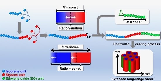
3.1. Strategy

In line with the introductory part, the main focus of this work is to develop a convergent synthesis route which enables the independent and systematic PIx and PSy block variation in BCPs with constantly the same PEOz block size, whereby the complete control over morphology and orientation of the BCP, especially of the very short PEOz block, should be obtained, as this is crucial for its possible application. For this purpose, PEOz blocks with an identical chain length were chosen and introduced into PIxPSyPEOz, in which the PIx and PSy blocks are synthesized by anionic polymerization of the monomers and therefore easily and precisely modified.
To do so, the commercially available and prefabricated mPEOz (Mn = 1.9 kg mol−1) was activated for the attachment by functionalization with an epoxide end group (yielding EmPEOz). In our synthesis route, the EmPEOz can be attached and thus covalently linked to the previously anionically synthesized PIxPSy carbanion by a simple one-step addition (cf. Scheme 2). Herein, it is important that an appropriate end group is selected, because it will have a great influence on the properties of the whole PEOz block of the BCP, especially in our focus of very short PEOz chains [49]. Thus, the use of an epoxide as an end group ensures that the formed junction point in PIxPSyAmPEOz hardly differs from the PIxPSyPEOz obtained by using EO gas, i.e., only by an additional OH-group. This smallest possible difference enables the selective consideration solely of the variation of the two nonpolar blocks between the different synthesized PIxPSyAmPEOz. There are approaches that have been reported in literature thus far in which, for instance, benzophenone or diphenylethylene were attached to the PEOz chain as terminal groups [49]. However, regarding the reported end group modifications, multi-step synthesis has to be employed, making the overall synthesis of a PIxPSyPEOz more complex, and these groups are more chemically different compared to the ether and OH-group with unintended influence on the polarity [50]. Especially in the case of short PEOz chains, this could have a great impact on its domain structure formation.
Considering the end group modification shown in Scheme 3, the PEOz block was end-capped with an epoxide group in a simple literature-known and modified one-pot reaction [51,52]. In the first modification step, the terminal OH-group of mPEOz is selectively deprotonated by a strong base, i.e., NaOtBu. Afterwards, the formed mPEOz alcoholate attacks the epoxide group of the added epichlorohydrin via a nucleophilic (SN2) attack to form the desired product EmPEOz (Scheme 3). This method can also be extended for longer (Mn = 6 kg mol−1) PEOz chains as reported by van Butsele et al. [52]. Here it should be mentioned, that the PEOz block has to be selectively functionalized at only one terminal OH-group. End-capping both terminal OH-groups would lead to the undesired formation of a symmetric five BCP (PIxPSyPEOzPSyPIx). As mPEOz only possess one terminal OH-group allowing for a distinct functionalization, the linkage to the PIxPSy anion happens in a selective manner, as indicated in (Scheme 3).
Another important aspect of the above-described usage of the prefabricated mPEOz block is the accurate characterization prior to its linkage, because a PEOz block that is already attached to the PIxPSy block is relatively small compared to the total BCP and therefore difficult to characterize and control accurately, especially in terms of its Đ.
The straightforward addition of EmPEOz to the reaction solution furthermore simplifies the polymerization by terminating the living PIxPSy anion because it allows a one-step attachment in the presence of the Li+ counterion in nonpolar solvent (Scheme 2II). After the addition of the EmPEOz to the reaction solution, the PIxPSy anion attacks the epoxy group of the EmPEOz via a ring-opening reaction forming an alcoholate group and a covalent bond between the PIxPSy block and the AmPEOz. Hence, the charge of the carbanion is transferred to the O-atom of the alcoholate group. The negative charge on the O-atom of the alcoholate group is directly blocked by the Li+ counterion, which strongly reduces the nucleophilicity. Therefore, a new ring-opening reaction with another epoxide group of a second EmPEOz molecule is inhibited due to the strong O-Li-ion pair (Scheme S1), thus blocking a further polymerization, or any other undesired crosslinking or side reaction and highlighting the advantage of this one-pot synthesis route (Scheme 2) [17,31,37,38,39,40]. Especially, a reaction of the living anions with O2 is suppressed, so that immediately after the AmPEOz block attachment, the product is stable in air, providing an advantage in terms of reproducibility and up-scalability [53,54,55].
Moreover, the epoxide functionalization allows the EmPEOz to be added to the reaction solution in minimal excess (cf. Table 1), so that the PIxPSy anions react stoichiometrically to form the PIxPSyAmPEOz and the excess and unbound EmPEO1.9 is easily washed out after the polymerization reaction.

3.2. Synthesis

Triblock copolymers were synthesized in one-pot polymerization in three subsequential steps by living anionic polymerization. As indicated by Scheme 2Ia, the PIx block was prepared from isoprene monomers using sec-BuLi serving as initiator for formation of the living carbanion. Subsequently, the living PIx anion was used for chain extension by addition of styrene (Scheme 2Ib). In the third step of this synthesis route, the PEOz block was covalently attached to the living PIxPSy anion via a one-step reaction of the epoxide group-functionalized EmPEOz and thus terminated the polymerization to the BCP (Scheme 2II). The coupling of EmPEOz to a PIxPSy anion enabled the selective and highly controllable preparation of PIxPSyAmPEOz in which the PEO1.9 block features an identical chain length and a Đ very close one in all cases. The respective Mn,PIx/Mn,PSy and thus the Mn,total of the BCP can be specifically tailored by systematically varying the used amount of initiator and the PIx and PSy monomers. However, as the living anionic polymerization is highly sensitive to impurities, because they directly lead to the termination of the corresponding living anion, special requirements for the synthesis conditions must always be ensured (cf. experimental section).
Here, it is worth noticing that the reaction of mPEOz to EmPEOz has to be quantitative, as no separation of both can be conducted due to the strong chemical similarity of mPEOz and EmPEOz. Even more, since acidic protons of residual mPEOz would protonate the PIxPSy anions upon addition and therefore inhibit the reaction of EmPEOz and the PIxPSy anions, the importance of a quantitative functionalization reaction is emphasized. In order to obtain a quantitative end group modification of mPEOz, the base used for deprotonation of the OH-group has to be a weak nucleophile, as otherwise it would compete with the formed mPEOz alcoholate regarding the SN2 reaction with epichlorohydrin, thus minimizing the yield of the desired EmPEOz. Additionally, the following conditions have been optimized for the quantitative formation of EmPEOz: (1) The use of NaOtBu and epichlorohydrin in excess (relative to the mPEOz). (2) The reaction has to be carried out under argon atmosphere using anhydrous reactants to ensure that the precipitation of the formed NaCl in THF is quantitatively [56]. Furthermore, the absence of H2O prohibits the formation of nucleophilic OH-ions, which would also compete with the formed mPEOz alcoholate regarding the reaction with epichlorohydrin.
By the use of EmPEO1.9, different BCPs with constant PEO1.9 block size were synthesized, using this universally applicable and simplified synthesis method, by systematically varying the Mn of their PIx and PSy blocks (cf. Scheme 1), namely PI6.8PS17.3AmPEO1.9, PI14.6PS34.8AmPEO1.9, PI24.8PS25.0AmPEO1.9, PI35.1PS14.8AmPEO1.9 and PI26.1PS67.3AmPEO1.9 (cf. Scheme 4). While the Mn,total of the BCP and thus the PEO1,9 block fraction remained constant, the Mn,PIx/Mn,PSy was varied (cf. Scheme 1a). According to this, for PI24.8PS25.0AmPEO1.9 the Mn,PIx is equal to the Mn,PSy, in the case of PI35.1PS14.8AmPEO1.9 the Mn,PIx is doubled compared to the Mn,PSy, whereas for PI14.6PS34.8AmPEO1.9 the Mn,PSy is two times larger than the Mn,PIx, which is exactly the opposite compared to PI35.1PS14.8AmPEO1.9.
In addition, by keeping a Mn,PIx/Mn,PSy constant, in which the Mn,PSy is doubled compared to the Mn,PIx, the PEO1.9 block proportion was varied by changing the Mn,total of the BCP (cf. Scheme 1b). Therefore, by halving the Mn,total of PI14.6PS34.8AmPEO1.9, the PEO1.9 block fraction was doubled in PI6.8PS17.3AmPEO1.9. In contrast, for PI26.1PS67.3AmPEO1.9 the Mn,total was varied exactly in the opposite way, i.e., the Mn,total of PI14.6PS34.8AmPEO1.9 was doubled, resulting in a reduced PEO1.9 block proportion.

3.3. NMR Characterization

3.3.1. EmPEO1.9

First, the EmPEO1.9 obtained from the functionalization reaction of mPEO1.9 (Scheme 3) was analyzed for its quality via 1H- and 13C-NMR to verify that the end group modification was quantitative as required. The 1H-NMR spectrum of EmPEO1.9 (Figure 1) shows the proton and satellite peaks (highlighted by the grey box) from the polyether chain in the chemical shift region of δ = 3.4–3.7 ppm (c in orange circle) [51,52]. The sharp singlet at δ = 3.3 ppm (d in grey circle) can be assigned to the three protons of the terminal methoxy group [51,52]. The three protons of the epoxide group attached by functionalization reaction split into three characteristic signals located at δ = 2.5 ppm (a in blue circle), δ = 2.7 ppm (a’ in blue circle) and δ = 3.1 ppm (b in yellow circle) [51,52]. The integrals of these three signals are equal and have a value of one with respect to the three protons of the terminal methoxy group, indicating that the attachment of the epoxide group took place quantitatively.
The comparison of the 13C-NMR spectra of mPEO1.9 and EmPEO1.9 (Figure 2) highlights the characteristic carbon signal changes due to the modification reaction (cf. for entire spectrum of mPEO1.9 Figure S4 and EmPEO1.9 Figure S2). For mPEO1.9 (Figure 2a), the carbon atom signal at δ = 61.7 ppm (a in dark blue circle) corresponds to the carbon atom directly linked to the OH-group and the signal at δ = 72.5 ppm to its directly adjacent carbon atom (b in yellow circle). Both carbon atom signals are not detected in the 13C-NMR spectrum of the EmPEO1.9 (Figure 2b), confirming that the functionalization of all OH-groups with epoxide groups to form EmPEO1.9 is quantitatively [51]. The carbon atoms of the polyether chain at δ = 70.5 ppm (c in orange circle) and the terminal methoxy group at δ = 59.0 ppm (e in light green circle) are not affected during the modification reaction, thus the respective signals can be found in both 13C-NMR spectra [51]. In contrast to the 13C-NMR spectrum of mPEO1.9 (Figure 2a), two carbon atom signals appear at δ = 44.1 ppm (f in light blue circle) and δ = 50.7 ppm (g in brown circle) in 13C-NMR spectrum of EmPEO1.9 (Figure 2b) which are characteristic for the attached epoxide group [51].
The successful and quantitative attachment of the epoxide group to the mPEO1.9 molecule was verified by the integrals in 1H-NMR as well as the altered signals in 13C-NMR. Furthermore, the absence of additional signals in the 1H- and 13C-NMR spectra of EmPEO1.9 (Figure 1 and Figure 2b) indicated that during the modification reaction, no side reaction occurred, and no impurities were introduced (cf. Figures S1 and S2 for entire spectrum).

3.3.2. PIxPSyAmPEO1.9

The quantitatively epoxy-functionalized EmPEO1.9 was used for the synthesis of different PIxPSyAmPEO1.9, which were subsequently characterized by 1H-NMR measurements. In the following, PI14.6PS34.8AmPEO1.9 is discussed exemplarily based on its 1H-NMR result, whereas in Figure S10 and Table S1, the results of all synthesized PIxPSyAmPEO1.9 are summarized, while the individual spectra are depicted in Figures S5–S9.
The 1H-NMR spectrum of PI14.6PS34.8AmPEO1.9 is displayed in Figure 3. The signals in the range of δ = 7.4–6.2 ppm can be assigned to the five aromatic protons of the phenyl group of PS34.8 block (red circles). The signal of the olefinic proton from the 1,4-PI14.6 block (blue circle) is located at δ = 5.2 ppm and the two terminal protons of the 3,4-PI14.6 block (blue circle) are located at δ = 4.8 and 4.7 ppm, respectively [57]. The integral ratio of the 1,4-PI14.6 block to the 3,4-PI14.6 block is 1.00: 0.15, being the same for all prepared PIxPSyAmPEO1.9 [57]. The protons of the polyether chain of the AmPEO1.9 (dark green circle) are localized at δ = 3.7 ppm. The signal at δ = 3.4 ppm can be attributed to the terminal methoxy group of AmPEO1.9 (light green circle), and the alkyl backbone protons of the entire PI14.6PS34.8AmPEO1.9 (light grey circles) are located in the range of δ = 2.3–1.3 ppm. The fact that the proton signals from AmPEO1.9 are still present after the purification procedure of PI14.6PS34.8AmPEO1.9 indicates that AmPEO1.9 was covalently linked to the PI14.6PS34.8 anion by a nucleophilic attack on the epoxide group of EmPEO1.9, as described previously (cf. Scheme 2II). The nonbonded EmPEO1.9 was removed during the purification procedure because it dissolves in MeOH, which is used in the purification process [58].
The theoretical molar mass (Mn,calc.) of the individual blocks shown in Table 2, which was calculated from the ratio of the used masses of monomers (isoprene and styrene) to sec-BuLi (initiator) (cf. Table 1), fit to the respective 1H-NMR integrals of the characteristic protons from the PIx, PSy and AmPEO1.9 blocks for all synthesized PIxPSyAmPEO1.9 (Table 3, Figure S10, Table S1).
Considering the fact that the molar masses (Mn,NMR) of the individual blocks shown in Table 3 determined from the respective proton number of 1H-NMR integrals (cf. Table S1) agree with the corresponding Mn,calc. indicates a nearly stoichiometric conversion of the utilized masses listed in Table 1 to the desired PIxPSyAmPEO1.9 without any side reactions. This close to quantitative polymerization process is due to the high reaction control by living anionic polymerization, the controlled synthesis conditions and the use of a slight excess of the EmPEO1.9 during the polymer synthesis. The slight excess (10%) of EmPEO1.9 ensures that all PIxPSy anions are stoichiometrically saturated with the corresponding AmPEO1.9 blocks, whereby the chosen epoxide end group modification ensures that not more than one EmPEO1.9 molecule can be covalently attached per PIxPSy anion (cf. Scheme 2 and Scheme S1). Therefore, the excess of unattached EmPEO1.9 was removed during the purification process. In addition, the strong O-Li-ion pair acts as a kind of protecting group, avoiding unwanted crosslinking, side and termination reactions.

3.4. GPC Measurements

The GPC measurements were conducted to determine the molar mass (Mn,GPC), to confirm the Mn,NMR results, the efficiency of the polymer synthesis and to determine the Đ of the EmPEO1.9 as well as the synthesized PIxPSyAmPEO1.9. The corresponding GPC traces are shown in Figure 4, and Table 4 lists the results (cf. Figures S11–S15 for the complete traces). From the GPC traces, it can be seen that all synthesized PIxPSyAmPEO1.9 polymers and EmPEO1.9 have a narrow, unimodal shape and as a result, a Đ smaller than 1.10. These are: PI6.8PS17.3AmPEO1.9 (Đ = 1.02), PI14.6PS34.8AmPEO1.9 (Đ = 1.02), PI24.8PS25.0AmPEO1.9 (Đ = 1.03), PI35.1PS14.8AmPEO1.9 (Đ = 1.03), PI26.1PS67.3AmPEO1.9 (Đ = 1.08) with an additional minor signal, and in comparison, EmPEO1.9 (Đ = 1.03). Moreover, it can be clearly observed by the overlapping of the traces that the Mn,GPC of PI14.6PS34.8AmPEO1.9, PI24.8PS25.0AmPEO1.9 and PI35.1PS14.8AmPEO1.9 are almost identical and in the range of Mn,GPC = 62.4–65.3 kg mol−1, whereas the Mn,GPC of PI6.8PS17.3AmPEO1.9 is shifted to a lower value at Mn,GPC = 31.2 kg mol−1 and for PI26.1PS67.3AmPEO1.9 to a higher value at Mn,GPC = 107.6 kg mol−1, which corresponds to their respective Mn,calc. and Mn,NMR (cf. Figure 4, Table 4). The deviation towards higher molar mass in the Mn,GPC compared to the Mn,NMR values is attributed to the fact that the GPCs used polystyrene calibration standards. Furthermore, the GPC trace of EmPEO1.9 with Mn,GPC = 2.8 kg mol−1 shows a very narrow chain length distribution of Đ = 1.03. Thus, it was successfully characterized prior to linkage, showing a major advantage over the short PEOz block control.
By linking the PEOz block via EmPEOz, it prevents unwanted chain termination caused by the introduction of impurities, which has a considerable influence on Đ.
The result that the Đ values are close to one (Đ ≤ 1.08) indicates that the synthesized PIxPSyAmPEOz polymer chains have nearly the same length, which means that there are almost no chain terminations during the polymerization process. This is consistent with the 1H-NMR results that the polymerization process is nearly quantitative and thus Mn,calc. = Mn,NMR. Therefore, this simplified polymerization procedure allows a fast and efficient polymer synthesis of tailored PIxPSyAmPEOz BCPs in a controlled and reproducible way.

3.5. Thermal Analysis

The synthesized PIxPSyAmPEO1.9 polymers were analyzed by DSC (cf. Figure 5a). Besides the thermal induced phase transitions, these measurements were carried out in order to obtain relevant information regarding the microphase separation.
The occurrence of the three characteristic thermal phase transitions, i.e., the glass transition temperature (ϑg) for the PIx phase ϑg,PIx in the range of −68 to −60 °C, the ϑg,PSy for the PSy phase in the range of 75 to 96 °C, as well as the melting point ϑmp,PEO1.9 of the PEO1.9 (from AmPEO1.9) at ~50 °C (cf. Figure S16 for DSC measurement of pure EmPEO1.9), evidence a microphase separation of the synthesized PIxPSyAmPEO1.9 BCPs (Table 5) [59]. The existence of ϑmp,PEO1.9 indicates the phase separation of the PEO1.9 block from both nonpolar blocks. An exception is PI26.1PS67.3AmPEO1.9, where the ϑmp,PEO1.9 is not detected. The reason for the absence of the ordered crystalline structure of the PEO1.9 chains in PI26.1PS67.3AmPEO1.9 can be attributed either to their low content of 1.7 wt.% or to the minimal contamination, which was detected in GPC measurement, so that the entire PEO1.9 block is amorphous. Moreover, the two ϑg and the ϑmp,PEO1.9 are equal to those of the pure polymer blocks, and the absence of additional ϑg and ϑmp suggests the exclusion of any mixing of the individual blocks even at the phase boundaries. In consequence of the high tendency of phase separation (affected by the nearly monodisperse polymer chain lengths (Đ ≤ 1.08)), a correlation between the chain length of the individual polymer blocks and the respective ϑg is observed. An increase of the block length, which corresponds to a higher Mn of the corresponding polymer block, leads to a shift of the ϑg to higher temperature; for instance, an increase in Mn,PSy by ~10 kg mol−1 leads to a ϑg,PSy temperature increase of ~5 °C (cf. Table 5). Furthermore, the fact that there is no mixing between different polymer blocks indicates that a linear dependence of change of heat capacity ΔCp with the weight fraction of the respective polymer block at ϑg is detected. For example, an increase in Mn,PIx of ~20 wt.% leads to a rise in the ΔCp,PIx by ~0.12 J (g K)−1 for the ϑg,PIx (Table 5).
In Figure 5b, the decomposition temperature at a weight loss of 5% (ϑd5) of EmPEO1.9 and the synthesized PIxPSyAmPEO1.9 polymers as determined by TGA measurements are shown. The ϑd5 values are similar and independent of the polymer composition, with a slight trend of decreasing ϑd5 with higher PIx content and range from 322 to 334 °C. Therefore, they have a high thermal stability for the application as polymer electrolyte templates.

3.6. Morphological Characterization

Based on the previous results, it is evident that this polymerization route provides precise control over the chain length distribution respectively structure on a molecular level. In the following, it is investigated how this in combination with the controlled solvent casting process affects the morphology of the membrane. In particular, the self-assembly induced highly ordered microphase separation, which was already observed from DSC measurement, is crucial for the properties of the PIxPSyAmPEO1.9 polymers and therefore plays a key role in their application. The morphology of all synthesized PIxPSyAmPEO1.9 is determined using SAXS, SEM and TEM measurements. The results of above-mentioned morphological characterizations performed on the PIxPSyAmPEO1.9 membranes are shown in Figure 6, Figure 7, Figure 8 and Figure 9 and Table 6, which were controlled-cast from THF without annealing them later.
SAXS measurements were performed at room temperature on the as-cast membranes for all synthesized PIxPSyAmPEO1.9. Figure 6 and Table 6 show the results. All of the synthesized PIxPSyAmPEO1.9 specimens exhibited strong scattering, as seen in the 2D SAXS patterns in Figure 7, Figure 8 and Figure S18, and a clear first scattering peak (q*), which was marked by a yellow filled circle in the SAXS curves in Figure 6, confirming the microphase separation [60,61].
Table 6. Summary of SAXS results determined at room temperature of the as-cast membranes of the different PIxPSyAmPEO1.9.
PolymerfPIx 1
/%
fPSy 1
/%
fPEO1.9 1
/%
q* 2
/nm−1
Phase 3d 4
/nm
rcylinder 5
/nm
φcylinder 6
/%
Domain Size 9
/nm
PI6.8PS17.3AmPEO1.9296560.32HEX22.46.129 (PI6.8)90
PI14.6PS34.8AmPEO1.9326530.20HEX35.710.434 (PI14.6)122
PI24.8PS25.0AmPEO1.9524530.20LAM31.7t 7 = 16.452 (PI24.8)LAM 886
PI35.1PS14.8AmPEO1.9712630.19HEX39.210.931 (PS14.8AmPEO1.9)63
PI26.1PS67.3AmPEO1.9336620.11HEX63.616.928 (PI26.1)147
1 fi = monomer volume fraction on basis of published homopolymer densities (ρPIx = 0.830, ρPSy = 0.969, ρPEOz = 1.064 in g cm−3) [61] and calculated using Mn,NMR (cf. Table 3). Note that these densities were determined for 140 °C, which may cause deviations. 2 q* is the position of the first scattering peak, determined by SAXS. 3 HEX = hexagonally close-packed cylindrical and LAM = lamella structure, determined by SAXS measurement. 4 d = average domain spacing. 5 rcylinder = radius of cylinder determined by SAXS. 6 φcylinder = volume fraction of cylinder based on ratio of rcylinder to d. 7 t = layer thickness determined by SAXS. 8 Volume fraction of lamella based on ratio of t to d. 9 Domain size = determined by SAXS.
In the SAXS curve of PI6.8PS17.3AmPEO1.9, in addition to the q* = 0.32 nm−1, additional peaks were measured at a relative peak position at q/q* of 1 , 3 , 4 and 7 , indicating a HEX structure (cf. Figure 6) [18]. The same characteristic scattering peaks of a microphase-separated HEX morphology are detected for the membranes consisting of PI14.6PS34.8AmPEO1.9, PI35.1PS14.8AmPEO1.9 and PI26.1PS67.3AmPEO1.9, as shown in Figure 6 [18]. However, all q values of these polymers are shifted in comparison to PI6.8PS17.3AmPEO1.9 to lower q values, whereby PI26.1PS67.3AmPEO1.9 has the lowest q* value with 0.11 nm-1. In the case of PI24.8PS25.0AmPEO1.9, the q* value = 0.20 nm−1 is the same as for PI14.6PS34.8AmPEO1.9 (0.20 nm−1) and PI35.1PS14.8AmPEO1.9 (0.19 nm−1). In addition to the q* peak, further peaks at a relative position of q/q* 2 and 3 are clearly observed for PI24.8PS25.0AmPEO1.9, indicating a LAM morphology (cf. Figure 6) [18,60].
The q* values were used to calculate the respective average domain spacing (d) for all PIxPSyAmPEO1.9; this means for a HEX structure, the distance is from cylinder to adjacent cylinder, and for a LAM structure, from center to the next center, which is listed in Table 6. In addition, from SAXS measurement of PI24.8PS25.0AmPEO1.9 the layer thickness (t) and for samples with the HEX morphology, the cylinder radius (rcylinder) were determined and summarized in Table 6. Details concerning the fits to the radially averaged SAXS data in Figure 6 and the values in Table 6 are given in the supporting information.
The extra hump in the SAXS curve from PI6.8PS17.3AmPEO1.9 at low q value = 0.16 nm−1, which therefore precedes the q* value = 0.32 nm−1 and was not fitted, comes most probably from heterogeneities in the structure on length scales larger than the unit cell. The reason that only the one peak is seen and the others are suppressed lies in the ratio of rcylinder and d because in this combination, the peaks fall on the minima and are suppressed.
For all investigated polymers, the PEO1.9 block is with a volume fraction (φ) of 2–6% too small to be detected by SAXS measurements. Thus, it was not necessary to include the PEO1.9 block in the fit, as from DSC measurements it is known to be phase-separated from the nonpolar blocks, so a simplified diblock model was used.
For all samples, the fit used to determine the morphology matches very well to the measured SAXS curve shapes (cf. plotted black line in the SAXS curves in Figure 6). Therefore, the calculated relative peak positions at q/q* (cf. black squares for HEX and black stars for LAM structure in Figure 6) fit almost perfectly to the maxima and minima in the respective obtained SAXS curves. The model used for the fitting is either using homogenous cylinder form factor for the HEX or platelets form factor for the LAM phases. Even with this rather simple model, a precise fit of the radially averaged scattering data was achieved. The φ for different blocks were calculated from the ratio of rcylinder or t to the fitted d and are listed in Table 6.
The d values calculated from measured q* correlate with the total Mn,NMR of the PIxPSyAmPEO1.9. This means that PI6.8PS17.3AmPEO1.9 possesses not only the smallest structure size with d = 22.4 nm, but also the fact that it is about half of the size compared to PI14.6PS34.8AmPEO1.9 with d = 35.7 nm, PI24.8PS25.0AmPEO1.9 with d = 31.7 nm and PI35.1PS14.8AmPEO1.9 with d = 39.2 nm. The same behavior, but this time reversed, is seen for PI26.1PS67.3AmPEO1.9, which not only has the largest structure size with d = 63.6 nm, but also its size is in comparison to PI14.6PS34.8AmPEO1.9, PI24.8PS25.0AmPEO1.9 and PI35.1PS14.8AmPEO1.9 about two times larger. Therefore, the structure size ratios of the different PIxPSyAmPEO1.9 to each other are in accurate accordance with their respective Mn,NMR (cf. Scheme 4, Table 4). Also, the measured rcylinder have the same relationship to each other as the previously described d (cf. Table 6).
Using the Mn,NMR of the individual polymer blocks (cf. Table 3) and on basis of published homopolymer densities (ρPIx = 0.830, ρPSy = 0.969, ρPEOz = 1.064 in g cm−3, note that these densities were determined for 140 °C, which may cause slight deviations) [61], the monomer volume fractions (fi) of the PIx block (fPIx), the PSy block (fPSy) and the PEO1.9 block (fPEO1.9) were calculated and listed in Table 6. For PI6.8PS17.3AmPEO1.9, PI14.6PS34.8AmPEO1.9 and PI26.1PS67.3AmPEO1.9, the volume ratio of the PIx block to the PSyAmPEO1.9 block always remains the same and was in the range of ~29–33% for fPIx and ~68–71% for fPSyAmPEO1.9. The volume fraction of the cylinder (φcylinder) was equal for all with ~28–34%, which matches very well with the fPIx. Accordingly, it was obvious that they have the same HEX structure. Consequently, the cylinder from the HEX structure corresponds to the PIx block, because the rcylinder ratio of the different polymers, i.e., PI6.8PS17.3AmPEO1.9, PI14.6PS34.8AmPEO1.9 and PI26.1PS67.3AmPEO1.9, agrees exactly with the respective Mn,NMR,PIx ratio. As a result, the HEX structures differ from each other only in terms of size.
The volume ratio for PI35.1PS14.8AmPEO1.9 with fPI35.1 = 71% and fPS14.8AmPEO1.9 = 29% is exactly the opposite compared to the previously discussed PIxPSyAmPEO1.9. The determined φcylinder with 31% matches quite closely with the fPS14.8AmPEO1.9. Consequently, the detected HEX structure fits accurately; however, due to the inverted volume fractions, a reverse phase with PS14.8AmPEO1.9 cylinders exists. Hence, rcylinder with a value of 10.9 nm corresponds to the Mn,NMR of PS14.8 and AmPEO1.9 block and is the same size as rcylinder of PI14.6PS34.8AmPEO1.9 as well as its Mn,NMR of the PI14.6 block. This fact confirms that PI35.1PS14.8AmPEO1.9 has the reverse phase of the HEX structure of the PI14.6PS34.8AmPEO1.9.
The measured LAM morphology for PI24.8PS25.0AmPEO1.9 with the volume ratio of fPI24.8 = 52% and fPS25.0AmPEO1.9 = 48% fits exactly with the determined almost equal volume fraction of lamella (φLAM) of the PI24.8 block with φLAM = 52% and 48% for the PS25.0AmPEO1.9 block.
Indeed, as expected from the PIxPSy phase diagram, the nearly symmetric PI24.8PS25.0AmPEO1.9 forms a LAM, while all other, more asymmetric PIxPSyAmPEO1.9 show a HEX morphology [18,24].
In order to visualize the previously described structures more clearly, corresponding 3D drawings were plotted based on the parameters obtained from the SAXS measurements with the assumption that the PEO1.9 block is fully phase-separated (cf. 3D drawings on the right site in Figure 6).
The obtained SAXS results match almost perfectly for all PIxPSyAmPEO1.9 with their respective polymer composition determined from NMR, thermal analysis and GPC measurements, and in particular, when they are compared with each other.
For all PIxPSyAmPEO1.9, the SAXS measurement results indicate a high degree of long-range order in the structure due to the strong scattering in the respective 2D SAXS pattern, but also due to the fact that the curve shape shows a number of clear peaks that agree very well with the fit as well as with the calculated peak positions. For instance, in PI24.8PS25.0AmPEO1.9 the presence of 2q* and 3q* suggests that the LAM morphology is present with a highly long-range arrangement [60,62].
In order to determine a more detailed, local long-range order as well as the orientation of the structure, SEM measurements were carried out. In particular, these two structural parameters of the membrane are crucial for the application of BCP as a structure-giving polymer matrix in electrolyte. In addition, the structure determined from the SAXS results is also checked. For this purpose, exemplary SEM measurements were performed on unstained ultra-thin sections of about 50 to 100 nm thickness from PI14.6PS34.8AmPEO1.9 for the HEX structure and from PI24.8PS25.0AmPEO1.9 for the LAM structure. In Scheme S2, the procedure of sample preparation by cryo-ultramicrotomy as well as sample placement onto the grid is schematically shown.
Results of PI14.6PS34.8AmPEO1.9 are shown in Figure 7; the ones for PI24.8PS25.0AmPEO1.9 are displayed in Figure 8. In (a), an overview image of several µm2 in size is shown. The marked area in a) was enlarged as inset in b) to make the structure visible in more detail (i.e., periodic lamellae or hexagonal cylinder arrangement). In (c), the fast Fourier transformation (FFT) of the area in (a) in case of the LAM and of the inlet (b) in case of the HEX structure is added to indicate the average orientation of the structure. The good contrast of the sample is achieved through the relatively low accelerating voltage of 30 kV used for STEM-imaging in the SEM. Hence, samples can be measured without staining. Additionally, in both figures under (d), the corresponding SAXS pattern is shown to compare it with the FFT spectrum.
For PI14.6PS34.8AmPEO1.9, a long-range and highly ordered HEX structure of cylinders is clearly visible in the overview image of Figure 7a, respectively, in the enlarged inset in (b) and corresponds with the SAXS result. In particular, it is remarkable that the hexagonal cylinder pattern of the HEX structure is clearly visible and almost identical in the FFT spectrum in (c) as well as in the SAXS pattern in (d). This means that the cylinders have the same arrangement and distance to each other in the macroscopic sample volume (2 mm sample diameter in the SAXS capillaries) and in the microscopic sample area in the SEM image and are aligned straight through the entire volume. Furthermore, from the SEM image, it is evident that for the cast film HEX structure, the cylinder axes are located in plane.
In case of PI24.8PS25.0AmPEO1.9 in the large overview image in Figure 8a, respectively, in the inset in b), a long-range and highly ordered LAM structure is clearly evident, which is also consistent with the SAXS result and corroborated by the 2D FFT result. The obtained 2D FFT spectrum reveals two “beam-like shapes” according to the LAM structure going vertical through the sample (cf. Figure 8c). Also, the SAXS pattern in Figure 8d shows the two “beam-like shapes” which differ from those in the FFT nearly only by the fact that they are slightly tilted. Most likely this is due to the placement of the sample into the SAXS capillary. Considering that the FFT spectrum and the SAXS pattern look almost the same, the lamellae are microscopically as well as macroscopically equally oriented and have the same distance to each other.
Moreover, a TEM image of PI24.8PS25.0AmPEO1.9 of the unstained membrane was obtained in STEM mode. Usually, stained samples are measured [18,24,63,64]. The TEM result shown in Figure 9 displays the same LAM structure as already seen in SEM.
As a result, PI14.6PS34.8AmPEO1.9 and PI24.8PS25.0AmPEO1.9 possess a nearly perfectly ordered HEX respectively LAM structure, at least over the total SEM and TEM measurement µm size area as well as the 2 mm thick sample volume for the SAXS measurement. Therefore, they show an extraordinary long-range orientation. The strongly distinct microphase separation, most likely caused by the very narrow polymer chain length distribution, in combination with the controlled solution casting process ensuring enough time for self-assembly, leads to these exceptional morphological properties. These properties are crucial for an excellent polymer electrolyte matrix, because the conductive pathways and finally the Li+ transport should be aligned almost optimally to each other over an extremely long range inside the BCP membrane.
Furthermore, particularly in case of PI24.8PS25.0AmPEO1.9, horizontal cutting artifacts can be recognized in the sample overview image as brighter and darker waves. This is a common cutting artifact of cryo-ultramicrotomy, which results from compression of the section during sectioning and extends perpendicular to the cutting direction [65]. As the cutting direction was perpendicular to the membrane and a ribbon of sections could be imaged on the grid by SEM, it is possible to determine the orientation of the lamellae within the membrane over a larger sample surface area and at several sample positions (cf. Scheme S2). The lamellae are arranged from top to bottom, i.e., vertically across the sample. Compression artefacts are perpendicular to the lamellae, indicating that the cutting direction across the membrane is the same as the orientation of the lamellae in the BCP. In other words, the lamellae are continuous aligned orthogonally to the polymer surface and therefore also at the potential use in electrolytes as a structure-giving BCP matrix to the electrode interface, i.e., connecting both electrodes to each other. It has already been shown in our patent that these BCPs can be used as a structure-giving BCP matrix in electrolytes to obtain very high ionic conductivities [43]. Such electrolytes provide comparable, and in some cases even better, ionic conductivities than those reported by Dörr and Pelz et al. [10,11,37].

4. Conclusions

Herein, we introduced a convergent synthesis method based on the modular principle, which ensures the access to well-defined PIxPSyPEOz linear triblock copolymers with consistently the same very short and precise PEOz block. For this purpose, a prefabricated and commercially available mPEOz block is used, which is selectively functionalized with an epoxy end group to EmPEOz. The EmPEOz block is covalently attached to the PIxPSy anion synthesized by living anionic polymerization and thus terminated to the corresponding BCP. Thereby, by utilizing the O-Li ion pair formation between the epoxide group of the EmPEOz and the living anion, it is ensured that only a single ring-opening reaction occurs. Therefore, the handling of EO gas monomers during the BCP polymerization can be avoided.
The systematic variation of the block length reveals two major and independent influences of the polymer structure. By varying the Mn,PIx/Mn,PSy at a constant Mn,total, the morphology could be precisely controlled. Alternatively, by changing the Mn,total at the same Mn,PIx/Mn,PSy, only the PEOz block fraction could be altered and adjusted, while keeping the morphology constant.
This simplified and reproducible one-pot polymerization, with 100% reaction efficiency, obtains highly ordered PIxPSyAmPEOz BCPs whose morphology can be largely controlled within the polymer membrane on microscopic and macroscopic levels. Largely controlled means at the microscopic or molecular level that the polymer chain lengths can be precisely selected, are nearly monodisperse and the respective BCP possesses a very high degree of phase separation. Moreover, the highly uniform polymer blocks combined with the controlled solution casting process lead to PIxPSyAmPEOz membranes with a very high and exceptionally long-range ordered structure up to the mm scale.
Overall, due to the always constant PEOz block size, the high control over the order and orientation of the morphology as well as the PEOz block fraction, these BCPs are suitable for subsequent targeted investigation of their influence as a structure-giving matrix in corresponding solid polymer electrolytes with respect to Li+ transport up to the macroscale level.

Supplementary Materials

The following supporting information can be downloaded at: https://www.mdpi.com/article/10.3390/polym15092128/s1, Scheme S1: Illustration of the utilization of the blocking effect for single EmPEOz chain attachment to the PIxPSy anion with Li+ as counterion due to the strong O-Li affinity. Figure S1: 1H-NMR spectrum of EmPEO1.9. Figure S2: 13C-NMR spectrum of EmPEO1.9. Figure S3: 1H-NMR spectrum of mPEO1.9. Figure S4: 13C-NMR spectrum of mPEO1.9. Figure S5: 1H-NMR spectrum of PI6.8PS17.3AmPEO1.9. Figure S6: 1H-NMR spectrum of PI14.6PS34.8AmPEO1.9. Figure S7: 1H-NMR spectrum of PI24.8PS25.0AmPEO1.9. Figure S8: 1H-NMR spectrum of PI35.1PS14.8AmPEO1.9. Figure S9: 1H-NMR spectrum of PI26.1PS67.3AmPEO1.9. Figure S10: Comparison of the characteristic signals in the 1H-NMR spectra of the synthesized PIxPSyAmPEO1.9. Table S1: Comparison of the number of protons determined from 1H-NMR integrals of the individual polymer blocks of the synthesized PIxPSyAmPEO1.9. Figure S11: Full GPC trace of PI6.8PS17.3AmPEO1.9. Figure S12: Full GPC trace of PI14.6PS34.8AmPEO1.9. Figure S13: Full GPC trace of PI24.8PS25.0AmPEO1.9. Figure S14: Full GPC trace of PI35.1PS14.8AmPEO1.9. Figure S15: Full GPC trace of PI26.1PS67.3AmPEO1.9. Figure S16: DSC measurement of EmPEO1.9. Figure S17: Exemplary photo of a colorless and transparent PIxPSyAmPEO1.9 membrane cast from THF. Figure S18: Two-dimensional SAXS patterns obtained at room temperature from the membrane in as-cast condition with a sample diameter of 2 mm of the synthesized PI6.8PS17.3AmPEO1.9, PI35.1PS14.8AmPEO1.9 and PI26.1PS67.3AmPEO1.9. Details concerning fits to radially averaged SAXS data. Scheme S2: Procedure of sample preparation by cryo-ultramicrotomy as well as sample placement onto the grid.

Author Contributions

Conceptualization, H.-D.W., M.G. and D.T.K.; validation, D.T.K.; investigation, D.T.K., S.K., V.S., A.J.B., M.D. and B.F.; resources, H.-D.W., S.F., M.W., J.M. and P.T.; writing—original draft preparation, D.T.K.; writing—review and editing, D.T.K., M.G., H.-D.W., S.F., S.K., M.D., B.F., V.S., A.J.B. and P.T.; visualization, D.T.K., M.G., S.K., B.F. and M.D.; supervision, H.-D.W., M.W. and M.G.; funding acquisition, H.-D.W., M.W. and P.T. All authors have read and agreed to the published version of the manuscript.

Funding

This research was funded by the German Federal Ministry of Education and Research (BMBF) within ‘FestBatt’ (13XP0175C), ‘FestBatt 2′ (03XP0429C) and ‘MEET-HiEnD III’ (03XP0258A).

Data Availability Statement

The data presented in this study are available from the corresponding authors on request.

Conflicts of Interest

The authors declare no conflict of interest.

References

  1. Allen, C.; Maysinger, D.; Eisenberg, A. Nano-engineering block copolymer aggregates for drug delivery. Colloids Surf. B Biointerfaces 1999, 16, 3–27. [Google Scholar] [CrossRef]
  2. Adams, M.L.; Lavasanifar, A.; Kwon, G.S. Amphiphilic block copolymers for drug delivery. J. Pharm. Sci. 2003, 92, 1343–1355. [Google Scholar] [CrossRef] [PubMed]
  3. Mai, Y.; Eisenberg, A. Self-assembly of block copolymers. Chem. Soc. Rev. 2012, 41, 5969–5985. [Google Scholar] [CrossRef] [PubMed]
  4. Nedelcu, M.; Lee, J.; Crossland, E.J.W.; Warren, S.C.; Orilall, M.C.; Guldin, S.; Hüttner, S.; Ducati, C.; Eder, D.; Wiesner, U.; et al. Block copolymer directed synthesis of mesoporous TiO2 for dye-sensitized solar cells. Soft Matter 2009, 5, 134–139. [Google Scholar]
  5. Perrin, L.; Phan, T.; Querelle, S.; Deratani, A.; Bertin, D. Polystyrene-block-poly(ethylene oxide)-block-polystyrene: A New Synthesis Method Using Nitroxide-Mediated Polymerization from Poly(ethylene oxide) Macroinitiators and Characterization of the Architecture Formed. Macromolecules 2008, 41, 6942–6951. [Google Scholar] [CrossRef]
  6. Bai, W.; Ross, C.A. Functional nanostructured materials based on self-assembly of block copolymers. MRS Bull. 2016, 41, 100–107. [Google Scholar] [CrossRef]
  7. Li, L.; Krissanasaeranee, M.; Pattinson, S.W.; Stefik, M.; Wiesner, U.; Steiner, U.; Eder, D. Enhanced photocatalytic properties in well-ordered mesoporous WO3. Chem. Commun. 2010, 46, 7620–7622. [Google Scholar] [CrossRef] [PubMed]
  8. Hu, H.; Gopinadhan, M.; Osuji, C.O. Directed self-assembly of block copolymers: A tutorial review of strategies for enabling nanotechnology with soft matter. Soft Matter 2014, 10, 3867–3889. [Google Scholar] [CrossRef]
  9. Dörr, T.S.; Fleischmann, S.; Zeiger, M.; Grobelsek, I.; de Oliveira, P.W.; Presser, V. Ordered Mesoporous Titania/Carbon Hybrid Monoliths for Lithium-ion Battery Anodes with High Areal and Volumetric Capacity. Chem. Eur. J. 2018, 24, 6358–6363. [Google Scholar] [CrossRef] [PubMed]
  10. Dörr, T.S.; Pelz, A.; Zhang, P.; Kraus, T.; Winter, M.; Wiemhöfer, H.-D. An Ambient Temperature Electrolyte with Superior Lithium Ion Conductivity based on a Self-Assembled Block Copolymer. Chem. Eur. J. 2018, 24, 8061–8065. [Google Scholar] [CrossRef] [PubMed]
  11. Pelz, A.; Dörr, T.S.; Zhang, P.; de Oliveira, P.W.; Winter, M.; Wiemhöfer, H.-D.; Kraus, T. Self-Assembled Block Copolymer Electrolytes: Enabling Superior Ambient Cationic Conductivity and Electrochemical Stability. Chem. Mater. 2019, 31, 277–285. [Google Scholar] [CrossRef]
  12. Butzelaar, A.J.; Röring, P.; Mach, T.P.; Hoffmann, M.; Jeschull, F.; Wilhelm, M.; Winter, M.; Brunklaus, G.; Théato, P. Styrene-Based Poly(ethylene oxide) Side-Chain Block Copolymers as Solid Polymer Electrolytes for High-Voltage Lithium-Metal Batteries. ACS Appl. Mater. Interfaces 2021, 13, 39257–39270. [Google Scholar] [CrossRef]
  13. Flory, P.J. Principles of Polymer Chemistry, 16th ed.; Cornell University Press: Ithaca, NY, USA, 1995; pp. 541–593. [Google Scholar]
  14. Bates, F.S. Polymer-Polymer Phase Behavior. Science 1991, 251, 898–905. [Google Scholar] [CrossRef]
  15. Leibler, L. Theory of microphase separation in block copolymers. Macromolecules 1980, 13, 1602–1617. [Google Scholar] [CrossRef]
  16. Lynd, N.A.; Meuler, A.J.; Hillmyer, M.A. Polydispersity and block copolymer self-assembly. Prog. Polym. Sci. 2008, 33, 875–893. [Google Scholar] [CrossRef]
  17. Hillmyer, M.A.; Bates, F.S. Synthesis and Characterization of Model Polyalkane−Poly(ethylene oxide) Block Copolymers. Macromolecules 1996, 29, 6994–7002. [Google Scholar] [CrossRef]
  18. Chatterjee, J.; Jain, S.; Bates, F.S. Comprehensive Phase Behavior of Poly(isoprene-b-styrene-b-ethylene oxide) Triblock Copolymers. Macromolecules 2007, 40, 2882–2896. [Google Scholar] [CrossRef]
  19. Bailey, T.S.; Pham, H.D.; Bates, F.S. Morphological Behavior Bridging the Symmetric AB and ABC States in the Poly(styrene-b-isoprene-b-ethylene oxide) Triblock Copolymer System. Macromolecules 2001, 34, 6994–7008. [Google Scholar] [CrossRef]
  20. Kimms, L.; Diddens, D.; Heuer, A. Understanding the Lithium Ion Transport in Concentrated Block–Copolymer Electrolytes on a Microscopic Level. arXiv 2020, arXiv:2010.11673. [Google Scholar]
  21. Kim, S.H.; Misner, M.J.; Xu, T.; Kimura, M.; Russell, T.P. Highly Oriented and Ordered Arrays from Block Copolymers via Solvent Evaporation. Adv. Mater. 2004, 16, 226–231. [Google Scholar] [CrossRef]
  22. Sun, Y.; Tan, R.; Ma, Z.; Zhou, D.; Li, J.; Kong, D.; Dong, X.-H. Quantify the contribution of chain length heterogeneity on block copolymer self-assembly. Giant 2020, 4, 100037. [Google Scholar] [CrossRef]
  23. Albert, J.N.; Epps, T.H. Self-assembly of block copolymer thin films. Mater. Today 2010, 13, 24–33. [Google Scholar] [CrossRef]
  24. Epps, T.H.; Cochran, E.W.; Bailey, T.S.; Waletzko, R.S.; Hardy, C.M.; Bates, F.S. Ordered Network Phases in Linear Poly(isoprene-b-styrene-b-ethylene oxide) Triblock Copolymers. Macromolecules 2004, 37, 8325–8341. [Google Scholar] [CrossRef]
  25. Coats, J.P.; Cochereau, R.; Dinu, I.A.; Messmer, D.; Sciortino, F.; Palivan, C.G. Trends in the Synthesis of Polymer Nano- and Microscale Materials for Bio-Related Applications. Macromol. Biosci. 2023, 2200474. [Google Scholar] [CrossRef]
  26. Xiang, L.; Li, Q.; Li, C.; Yang, Q.; Xu, F.; Mai, Y. Block Copolymer Self-Assembly Directed Synthesis of Porous Materials with Ordered Bicontinuous Structures and Their Potential Applications. Adv. Mater. 2023, 35, 2207684. [Google Scholar] [CrossRef]
  27. Qi, H.; Xie, R.; Yang, G.-W.; Zhang, Y.-Y.; Xu, C.-K.; Wang, Y.; Wu, G.-P. Rational Optimization of Bifunctional Organoboron Catalysts for Versatile Polyethers via Ring-Opening Polymerization of Epoxides. Macromolecules 2022, 55, 9081–9090. [Google Scholar] [CrossRef]
  28. Quirk, R.P.; Zhuo, Q.; Jang, S.H.; Lee, Y.; Lizarraga, G. Applications of Anionic Polymerization Research; Principles of Anionic Polymerization: An Introduction; American Chemical Society: Washington, DC, USA, 1998; pp. 2–27. [Google Scholar]
  29. Jagur-Grodzinski, J. Functional polymers by living anionic polymerization. J. Polym. Sci. Part A Polym. Chem. 2002, 40, 2116–2133. [Google Scholar] [CrossRef]
  30. Merck Ethylene Oxide. Available online: https://www.sigmaaldrich.com/DE/en/product/sial/03906 (accessed on 28 March 2022).
  31. Förster, S.; Krämer, E. Synthesis of PB−PEO and PI−PEO Block Copolymers with Alkyllithium Initiators and the Phosphazene Base t-BuP4. Macromolecules 1999, 32, 2783–2785. [Google Scholar] [CrossRef]
  32. Herzberger, J.; Niederer, K.; Pohlit, H.; Seiwert, J.; Worm, M.; Wurm, F.R.; Frey, H. Polymerization of Ethylene Oxide, Propylene Oxide, and Other Alkylene Oxides: Synthesis, Novel Polymer Architectures, and Bioconjugation. Chem. Rev. 2016, 116, 2170–2243. [Google Scholar] [CrossRef] [PubMed]
  33. Esswein, B.; Möller, M. Polymerization of Ethylene Oxide with Alkyllithium Compounds and the Phosphazene Base “tBu-P4”. Angew. Chem. Int. Ed. Engl. 1996, 35, 623–625. [Google Scholar] [CrossRef]
  34. Brocas, A.-L.; Mantzaridis, C.; Tunc, D.; Carlotti, S. Polyether synthesis: From activated or metal-free anionic ring-opening polymerization of epoxides to functionalization. Prog. Polym. Sci. 2013, 38, 845–873. [Google Scholar] [CrossRef]
  35. Dreier, P.; Ahn, J.; Chang, T.; Frey, H. End Group Functionality of 95–99%: Epoxide Functionalization of Polystyryl-Lithium Evaluated via Solvent Gradient Interaction Chromatography. Macromol. Rapid Commun. 2022, 43, 2200560. [Google Scholar] [CrossRef] [PubMed]
  36. Gao, T.; Xia, X.; Tajima, K.; Yamamoto, T.; Isono, T.; Satoh, T. Polyether/Polythioether Synthesis via Ring-Opening Polymerization of Epoxides and Episulfides Catalyzed by Alkali Metal Carboxylates. Macromolecules 2022, 55, 9373–9383. [Google Scholar] [CrossRef]
  37. Quirk, R.P.; Pickel, D.L.; Hasegawa, H. Anionic Polymerization Chemistry of Epoxides: Electron-Transfer Processes. Macromol. Symp. 2005, 226, 69–78. [Google Scholar] [CrossRef]
  38. Tonhauser, C.; Frey, H. A Road Less Traveled to Functional Polymers: Epoxide Termination in Living Carbanionic Polymer Synthesis. Macromol. Rapid Commun. 2010, 31, 1938–1947. [Google Scholar] [CrossRef]
  39. Tonhauser, C.; Golriz, A.A.; Moers, C.; Klein, R.; Butt, H.-J.; Frey, H. Stimuli-Responsive Y-Shaped Polymer Brushes Based on Junction-Point-Reactive Block Copolymers. Adv. Mater. 2012, 24, 5559–5563. [Google Scholar] [CrossRef] [PubMed]
  40. Natalello, A.; Alkan, A.; Friedel, A.; Lieberwirth, I.; Frey, H.; Wurm, F.R. Enlarging the Toolbox: Epoxide Termination of Polyferrocenylsilane (PFS) as a Key Step for the Synthesis of Amphiphilic PFS–Polyether Block Copolymers. ACS Macro Lett. 2013, 2, 313–316. [Google Scholar] [CrossRef] [PubMed]
  41. Zhang, J.; Pointer, W.; Patias, G.; Al-Shok, L.; Hand, R.A.; Smith, T.; Haddleton, D.M. End functionalization of polyisoprene and polymyrcene obtained by anionic polymerization via one-pot ring-opening mono-addition of epoxides. Eur. Polym. J. 2023, 183, 111755. [Google Scholar] [CrossRef]
  42. Pearson, R.G. Hard and soft acids and bases. J. Am. Chem. Soc. 1963, 85, 3533–3539. [Google Scholar]
  43. Krause, D.; Grünebaum, M.; Wiemhöfer, H.-D.; Winter, M. Improved Synthesis for Producing Ordered Poly-Block Copolymers Having a Controllable Molecular Weight Distribution. International Patent Application No. PCT/WO 2022/008615 A1, 23 January 2023. [Google Scholar]
  44. Lochmann, L.; Pospíšil, J.; Lím, D. On the interaction of organolithium compounds with sodium and potassium alkoxides. A new method for the synthesis of organosodium and organopotassium compounds. Tetrahedron Lett. 1966, 7, 257–262. [Google Scholar] [CrossRef]
  45. Long, T.E.; Liu, H.Y.; Schell, B.A.; Teegarden, D.M.; Uerz, D.S. Determination of solution polymerization kinetics by near-infrared spectroscopy. 1. Living anionic polymerization processes. Macromolecules 1993, 26, 6237–6242. [Google Scholar] [CrossRef]
  46. Fulmer, G.R.; Miller, A.J.M.; Sherden, N.H.; Gottlieb, H.E.; Nudelman, A.; Stoltz, B.M.; Bercaw, J.E.; Goldberg, K.I. NMR Chemical Shifts of Trace Impurities: Common Laboratory Solvents, Organics, and Gases in Deuterated Solvents Relevant to the Organometallic Chemist. Organometallics 2010, 29, 2176–2179. [Google Scholar] [CrossRef]
  47. Biehl, R. Jscatter, a program for evaluation and analysis of experimental data. PLoS ONE 2019, 14, e0218789. [Google Scholar] [CrossRef] [PubMed]
  48. Förster, S.; Apostol, L.; Bras, W. Scatter: Software for the analysis of nano- and mesoscale small-angle scattering. J. Appl. Crystallogr. 2010, 43, 639–646. [Google Scholar] [CrossRef]
  49. Graf, M. Polarmodifikation von Butadienkautschuk mit Polyethylenglykol. Ph.D. Thesis, Universität Bayreuth, Bayreuth, Germany, 28 October 2002. [Google Scholar]
  50. Zhang, B.; Zhang, Y.; Zhang, N.; Liu, J.; Cong, L.; Liu, J.; Sun, L.; Mauger, A.; Julien, C.M.; Xie, H.; et al. Synthesis and interface stability of polystyrene-poly(ethylene glycol)-polystyrene triblock copolymer as solid-state electrolyte for lithium-metal batteries. J. Power Sources 2019, 428, 93–104. [Google Scholar] [CrossRef]
  51. Liu, Y.; Wang, Y.; Wang, Y.; Lu, J.; Piñón, V.; Weck, M. Shell Cross-Linked Micelle-Based Nanoreactors for the Substrate-Selective Hydrolytic Kinetic Resolution of Epoxides. J. Am. Chem. Soc. 2011, 133, 14260–14263. [Google Scholar] [CrossRef] [PubMed]
  52. van Butsele, K.; Stoffelbach, F.; Jérôme, R.; Jérôme, C. Synthesis of Novel Amphiphilic and pH-Sensitive ABC Miktoarm Star Terpolymers. Macromolecules 2006, 39, 5652–5656. [Google Scholar] [CrossRef]
  53. Bhanu, V.A.; Kishore, K. Role of oxygen in polymerization reactions. Chem. Rev. 1991, 91, 99–117. [Google Scholar] [CrossRef]
  54. Wurm, F.; Wilms, D.; Klos, J.; Löwe, H.; Frey, H. Carbanions on Tap–Living Anionic Polymerization in a Microstructured Reactor. Macromol. Chem. Phys. 2008, 209, 1106–1114. [Google Scholar] [CrossRef]
  55. Castle, T.C. Synthesis of Block Copolymers by the Conversion of Living Anionic Polymerisation Into Living ROMP. Ph.D. Thesis, Durham University, Durham, UK, 13 June 2005. [Google Scholar]
  56. Chang, N.N.; Daly, S.R.; Girolami, G.S. Salt elimination reactions do not always eliminate. Mechanistic study of the reaction of NdCl3 with sodium N,N-dimethylaminodiboranate. Polyhedron 2019, 162, 52–58. [Google Scholar] [CrossRef]
  57. Surakit, T.; Adun, N.; Jitladda, T.S. Quantitative analysis of isoprene units in natural rubber and synthetic polyisoprene using 1H-NMR spectroscopy with an internal standard. Polym. Test. 2015, 43, 21–26. [Google Scholar]
  58. Toolan, D.T.W.; Isakova, A.; Hodgkinson, R.; Reeves-McLaren, N.; Hammond, O.S.; Edler, K.J.; Briscoe, W.H.; Arnold, T.; Gough, T.; Topham, P.D.; et al. Insights into the Influence of Solvent Polarity on the Crystallization of Poly(ethylene oxide) Spin-Coated Thin Films via In Situ Grazing Incidence Wide-Angle X-ray Scattering. Macromolecules 2016, 49, 4579–4586. [Google Scholar] [CrossRef]
  59. Butzelaar, A.J.; Röring, P.; Hoffmann, M.; Atik, J.; Paillard, E.; Wilhelm, M.; Winter, M.; Brunklaus, G.; Theato, P. Advanced Block Copolymer Design for Polymer Electrolytes: Prospects of Microphase Separation. Macromolecules 2021, 54, 11101–11112. [Google Scholar] [CrossRef]
  60. Sakurai, S.; Momii, T.; Taie, K.; Shibayama, M.; Nomura, S.; Hashimoto, T. Morphology transition from cylindrical to lamellar microdomains of block copolymers. Macromolecules 1993, 26, 485–491. [Google Scholar] [CrossRef]
  61. Fetters, L.J.; Lohse, D.J.; Richter, D.; Witten, T.A.; Zirkel, A. Connection between Polymer Molecular Weight, Density, Chain Dimensions, and Melt Viscoelastic Properties. Macromolecules 1994, 27, 4639–4647. [Google Scholar] [CrossRef]
  62. Isono, T.; Kawakami, N.; Watanabe, K.; Yoshida, K.; Otsuka, I.; Mamiya, H.; Ito, H.; Yamamoto, T.; Tajima, K.; Borsali, R. Microphase separation of carbohydrate-based star-block copolymers with sub-10 nm periodicity. Polym. Chem. 2019, 10, 1119–1129. [Google Scholar] [CrossRef]
  63. Chintapalli, M.; Le, T.N.P.; Venkatesan, N.R.; Mackay, N.G.; Rojas, A.A.; Thelen, J.L.; Chen, X.C.; Devaux, D.; Balsara, N.P. Structure and Ionic Conductivity of Polystyrene-block-poly(ethylene oxide) Electrolytes in the High Salt Concentration Limit. Macromolecules 2016, 49, 1770–1780. [Google Scholar] [CrossRef]
  64. Zhu, L.; Cheng, S.Z.D.; Calhoun, B.H.; Ge, Q.; Quirk, R.P.; Thomas, E.L.; Hsiao, B.S.; Yeh, F.; Lotz, B. Phase structures and morphologies determined by self-organization, vitrification, and crystallization: Confined crystallization in an ordered lamellar phase of PEO-b-PS diblock copolymer. Polymer 2001, 42, 5829–5839. [Google Scholar] [CrossRef]
  65. Michler, G.H. Electron Microscopy of Polymers; Preparation of Thin Sections: (Cryo)ultramicrotomy and (Cryo)microtomy; Springer Laboratory: Berlin/Heidelberg, Germany, 2008; pp. 199–217. [Google Scholar]
Scheme 1. Controlled compositional variations of the synthetized PIxPSyPEOz BCP by systematically and independently altering the PIx and PSy block lengths while keeping the PEOz block constant. (a) Changing the ratio of the Mn of the PIx to the PSy block (Mn,PIx/Mn,PSy) by keeping the total Mn of the BCP (Mn,total) constant and therefore retaining identical PEOz block proportion. (b) Variation of the PEOz block proportion in the BCP by altering the Mn,total and holding Mn,PIx/Mn,PSy = constant.
Polymers 15 02128 sch001
Scheme 2. Synthesis routes towards PIxPSyPEOz triblock copolymers. (I) Illustration of the living anionic polymerization forming the PIxPSy anion with Li+ as counterion, whereas each block is obtained from the respective monomers. (II) Final linkage of the PEOz block to the PIxPSy anion using EmPEOz. The formation of the O-Li-ion pair inhibits further ring-opening polymerization and is highlighted by a dotted circle. For clarity, the sec-butyl group resulting from sec-butyllithium is drawn only once at the beginning.
Polymers 15 02128 sch002
Scheme 3. End group modification of mPEOz to selectively attach a terminal epoxide group to yield EmPEOz.
Polymers 15 02128 sch003
Scheme 4. Comparison of the block weight ratio of the prepared PIxPSyAmPEO1.9, which are systematically and independently varied with constantly always the same PEO1.9 block size. The polymer chain length of each block is shown in relation to the theoretical Mn,calc. calculated from the ratio of the used masses of monomers to initiator (cf. Table 1).
Polymers 15 02128 sch004
Figure 1. 1H-NMR spectrum of the reaction product EmPEO1.9 obtained by the functionalization reaction of mPEO1.9 with epichlorohydrin (Scheme 3). The integrated signals indicate a quantitative formation of EmPEO1.9. The protons of the bridging CH2-group (between epoxide group and the polyether chain) as well as the satellite signals of the polyether chain are highlighted by the grey box.
Polymers 15 02128 g001
Figure 2. (a) 13C-NMR spectrum of mPEO1.9 and (b) of EmPEO1.9. The absence of signals a and b in 13C-NMR spectrum of EmPEO1.9 indicates the quantitative formation. For better clarity, the most intense signal (marked by c in filled orange circle) was cut off, symbolized by inserted tilde.
Polymers 15 02128 g002
Figure 3. 1H-NMR spectrum of the PI14.6PS34.8AmPEO1.9 obtained by the synthesis route with EmPEO1.9 (Scheme 2) after precipitation and drying. The presence of the AmPEO1.9 proton signals after purification procedure indicates that the AmPEO1.9 was covalently attached to the PI14.6PS34.8 anion. The integral of the protons fit to the theoretical molar mass (Mn,calc.) of the individual blocks, which implies 100% reaction efficiency. The protons of the butyl group (shown in the structural formula, originating from the sec-BuLi) were not displayed in the spectrum for a better overview.
Polymers 15 02128 g003
Figure 4. GPC traces of EmPEO1.9 as well as of the synthesized PIxPSyAmPEO1.9 polymers after the linkage of EmPEO1.9. The same narrow signal shape of all synthesized PIxPSyAmPEO1.9 as well as of the EmPEO1.9 indicate their nearly monodisperse polymer chain lengths (Đ ≤ 1.08). For PI26.1PS67.3AmPEO1.9, a very small additional signal was detected.
Polymers 15 02128 g004
Figure 5. (a) DSC measurements of the synthesized PIxPSyAmPEO1.9 polymers, which show that they are microphase-separated as proven by the distinct ϑg (glass transition temperature) of the PIx and PSy phase as well as the ϑmp (melting point) of the PEO1.9 phase. An exception is PI26.1PS67.3AmPEO1.9, where the ϑmp,PEO1.9 is not detected. (b) TGA curves of the EmPEO1.9 and the synthesized PIxPSyAmPEO1.9 BCPs and their respective decomposition temperature at 5% weight loss (ϑd5).
Polymers 15 02128 g005
Figure 6. SAXS curves measured at room temperature of as-cast membranes from the synthesized PIxPSyAmPEO1.9, by plotting the scattering intensity as a function of the magnitude of the scattering vector (q). The first reflection peak (q*) determined from SAXS measurement is marked by a yellow filled circle. Black squares with the values below indicate the calculated relative peak positions at q/q* due to hexagonally close-packed cylindrical structure and black stars indicate the respective peaks due to the lamellar structure. The theoretical fit for the morphology (black lines) and the curve obtained from SAXS measurement, as well as the calculated peak positions, match almost perfectly. On the right side are 3D drawings of the corresponding structure, therein blue represents PIx, red PSy and green PEO1.9 volume fraction and the size ratios of the drawing are equal to the average domain spacing (d) obtained from SAXS measurement.
Polymers 15 02128 g006
Figure 7. SEM images obtained at room temperature of self-assembled hexagonally close-packed cylindrical (HEX) domains in a 50 nm thick section of unstained as-cast membrane of PI14.6PS34.8AmPEO1.9 without subsequent annealing. (a) Sample overview. (b) Zoomed area of inset marked in (a). For better visibility, the hexagonal cylinder pattern of the HEX structure is marked in black as an example. (c) Two-dimensional FFT spectrum of inset area. (d) Two-dimensional SAXS pattern obtained at room temperature from the membrane in as-cast condition with a sample diameter of 2 mm.
Polymers 15 02128 g007
Figure 8. SEM images obtained at room temperature from an ultra-thin section of self-assembled lamellar domains of unstained as-cast membrane of PI24.8PS25.0AmPEO1.9 without subsequent annealing. (a) Sample overview. (b) Zoomed image of area marked in the overview image in (a). (c) Two-dimensional FFT spectrum over the entire overview image (a). (d) Two-dimensional SAXS pattern obtained at room temperature from the membrane in as-cast condition with a sample diameter of 2 mm.
Polymers 15 02128 g008
Figure 9. STEM image obtained at room temperature from a 50 nm thick section of self-assembled lamellar domains of an unstained as-cast membrane of PI24.8PS25.0AmPEO1.9 without subsequent annealing.
Polymers 15 02128 g009
Table 1. Overview of sec-BuLi (initiator), monomers (isoprene and styrene) and EmPEO1.9 used for the synthesis of PIxPSyAmPEO1.9.
Polymern (sec-BuLi)
/mmol
n (Isoprene)
/mmol
n (Styrene)
/mmol
n (EmPEO1.9)
/mmol
PI6.8PS17.3AmPEO1.90.25625.642.50.282
PI14.6PS34.8AmPEO1.90.24953.183.10.274
PI24.8PS25.0AmPEO1.90.13248.031.50.145
PI35.1PS14.8AmPEO1.90.233119.933.20.257
PI26.1PS67.3AmPEO1.90.14856.695.30.163
Table 2. Theoretical constitutional repeating units (CRUcalc.) and molar masses (Mn,calc.) of the individual blocks from the synthesized PIxPSyAmPEO1.9, calculated from the ratio of the used masses of monomers to initiator (cf. Table 1).
PolymerMn,calc.
/kg mol−1
PIx
CRUcalc.
Mn,calc.,PIx
/kg mol−1
PSy
CRUcalc.
Mn,calc.,PSy
/kg mol−1
PEO1.9
CRUcalc.
Mn,calc.,PEO1.9
/kg mol−1
PI6.8PS17.3AmPEO1.926.01006.816617.3431.9
PI14.6PS34.8AmPEO1.951.321414.633434.8431.9
PI24.8PS25.0AmPEO1.951.736524.824025.0431.9
PI35.1PS14.8AmPEO1.951.851635.114214.8431.9
PI26.1PS67.3AmPEO1.995.338426.164667.3431.9
Table 3. Practical constitutional repeating units (CRUNMR) and molar masses (Mn,NMR) of the individual polymer blocks from the synthesized PIxPSyAmPEO1.9 determined from the respective protons number of 1H-NMR integrals.
PolymerMn,NMR
/kg mol−1
PIx
CRUNMR
Mn,NMR,PIx
/kg mol−1
PSy
CRUNMR
Mn,NMR,PSy
/kg mol−1
PEO1.9
CRUNMR
Mn,NMR,PEO1.9
/kg mol−1
PI6.8PS17.3AmPEO1.926.81016.917418.1421.9
PI14.6PS34.8AmPEO1.949.720614.032433.8441.9
PI24.8PS25.0AmPEO1.949.734623.623124.1452.0
PI35.1PS14.8AmPEO1.949.648933.313714.3452.0
PI26.1PS67.3AmPEO1.9106.246031.370273.1411.8
Table 4. Overview of the theoretical molar mass (Mn,calc.), the molar mass determined via 1H-NMR measurement (Mn,NMR) and the molar mass obtained from GPC measurement (Mn,GPC) as well as the dispersity (Đ) of EmPEO1.9 and the different synthesized PIxPSyAmPEO1.9 polymers.
PolymerMn,calc. 1
/kg mol−1
Mn,NMR 2
/kg mol−1
Mn,GPC 3
/kg mol−1
Đ 3
EmPEO1.91.92.02.81.03
PI6.8PS17.3AmPEO1.926.026.831.21.02
PI14.6PS34.8AmPEO1.951.349.765.31.02
PI24.8PS25.0AmPEO1.951.749.762.41.03
PI35.1PS14.8AmPEO1.951.849.663.01.03
PI26.1PS67.3AmPEO1.995.3106.2107.61.08
1 Calculated from the ratio of the used masses of monomers to initiator (cf. Table 2). 2 Determined from the respective proton number of 1H-NMR integrals (cf. Figure S10, Table S1). 3 Determined by GPC measurement in THF using polystyrene standards (cf. Figure 4).
Table 5. Overview of the weight fractions (wt.%), the thermal induced phase transitions ϑmp (melting point), ϑg (glass transition temperature) and the ΔCp (heat capacity changes) of the individual polymer blocks well as the ϑd5 (decomposition temperature at 5% weight loss) of the different PIxPSyAmPEO1.9.
PolymerPIx 1
/wt.%
PSy 1
/wt.%
PEO1.9 1
/wt.%
ϑg,PIx 2
/°C
ΔCp,PIx 2
/J (g K)−1
ϑg,PSy 2
/°C
ΔCp,PSy 2
/J (g K)−1
ϑmp,PEO1.9 2
/°C
ϑd5 3
/°C
PI6.8PS17.3AmPEO1.925.667.56.9−63.70.1374.60.1250.2331
PI14.6PS34.8AmPEO1.928.268.03.9−65.90.1486.80.2450.6331
PI24.8PS25.0AmPEO1.947.548.54.0−60.70.2780.90.1449.9327
PI35.1PS14.8AmPEO1.967.228.84.0−60.10.3776.10.0649.9324
PI26.1PS67.3AmPEO1.929.568.81.7−67.60.1495.80.21-334
1 Calculated using Mn,NMR (cf. Table 3). 2 Determined by DSC measurement (cf. Figure 5a). 3 Determined by TGA measurement (cf. Figure 5b).
Disclaimer/Publisher’s Note: The statements, opinions and data contained in all publications are solely those of the individual author(s) and contributor(s) and not of MDPI and/or the editor(s). MDPI and/or the editor(s) disclaim responsibility for any injury to people or property resulting from any ideas, methods, instructions or products referred to in the content.

