
Experimentation and Numerical Modeling of Peak Temperature in the Weld Joint during Rotary Friction Welding of Dissimilar Plastic Rods


Abstract
:1. Introduction
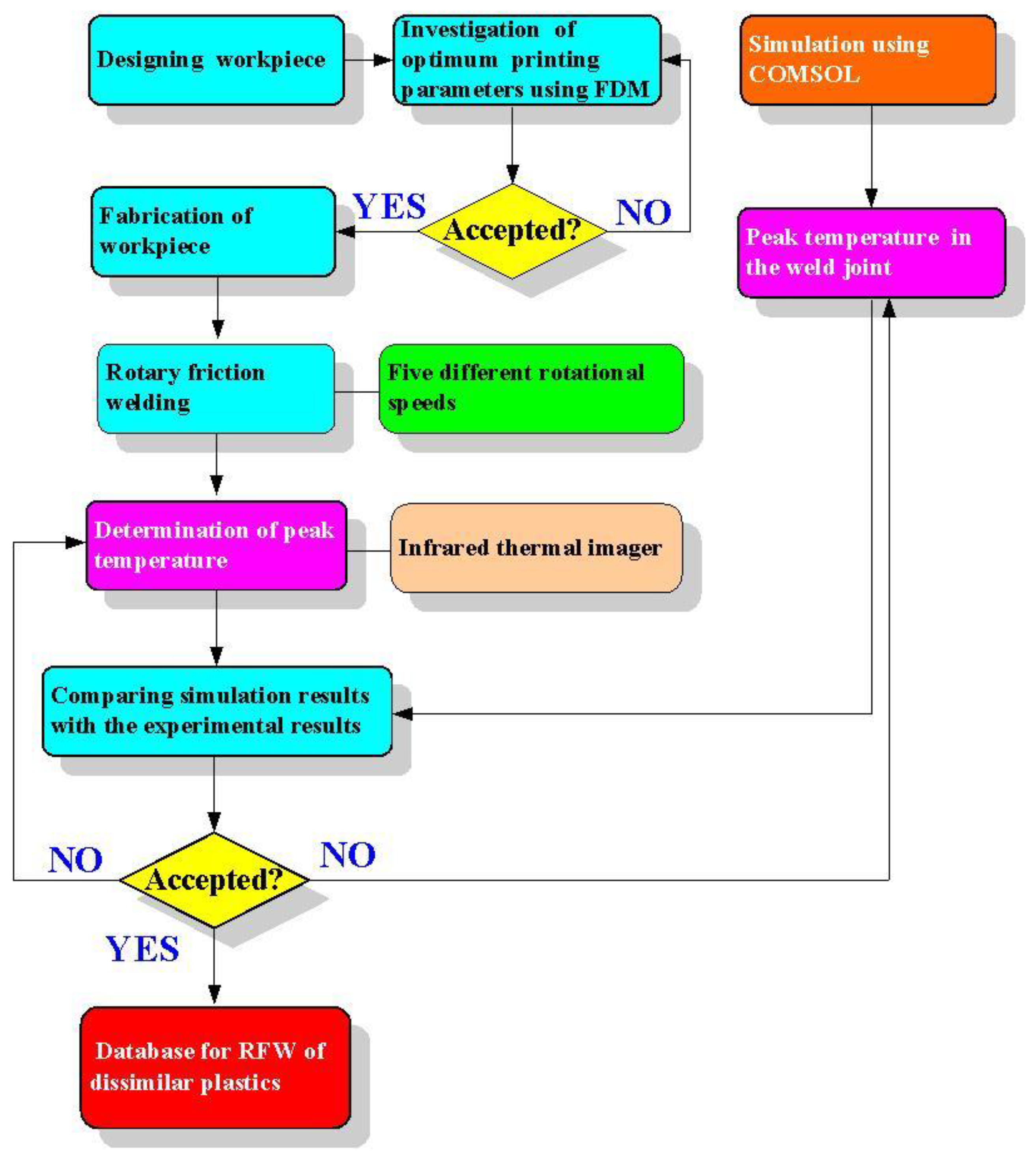
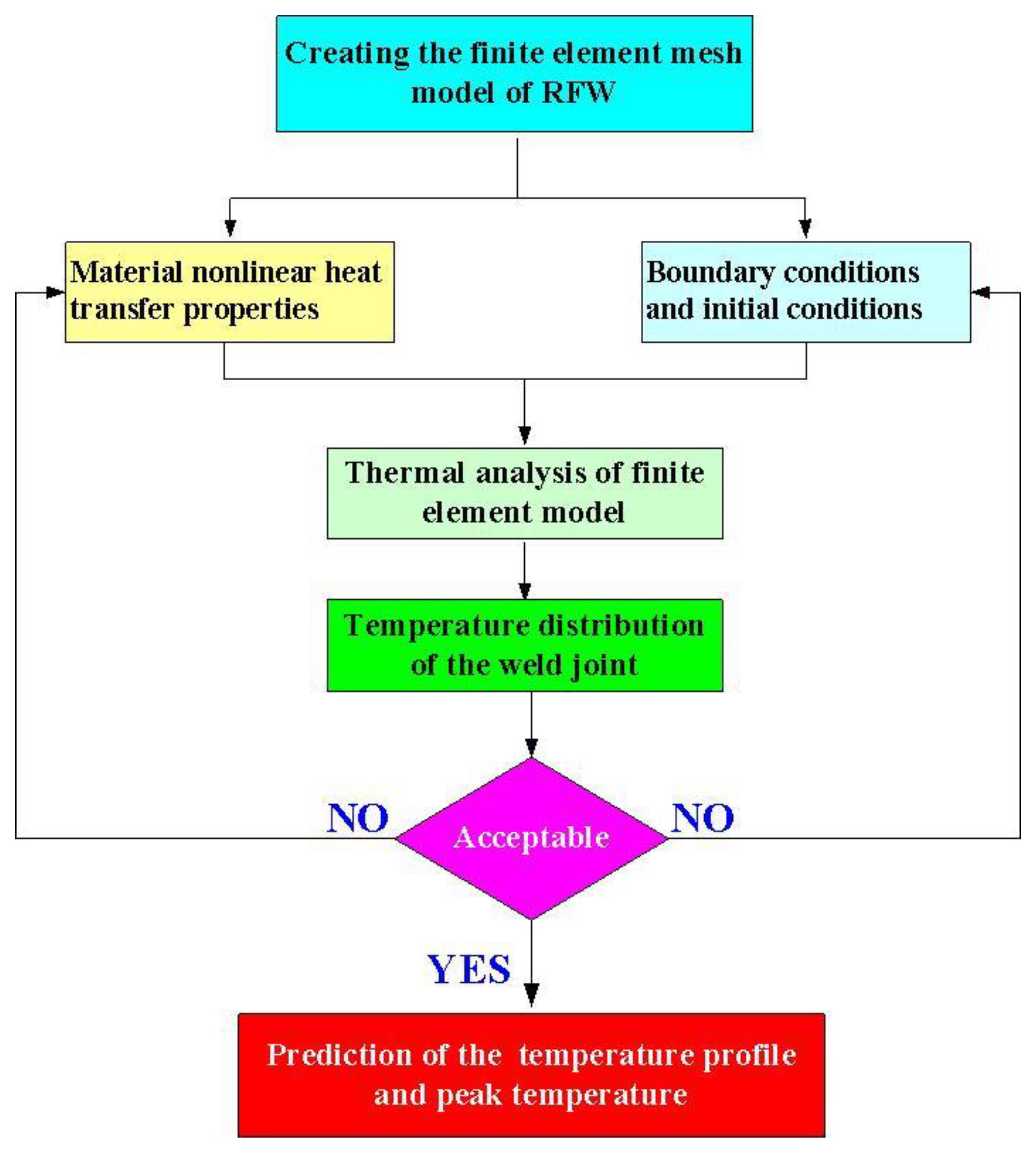
2. Experimental Details
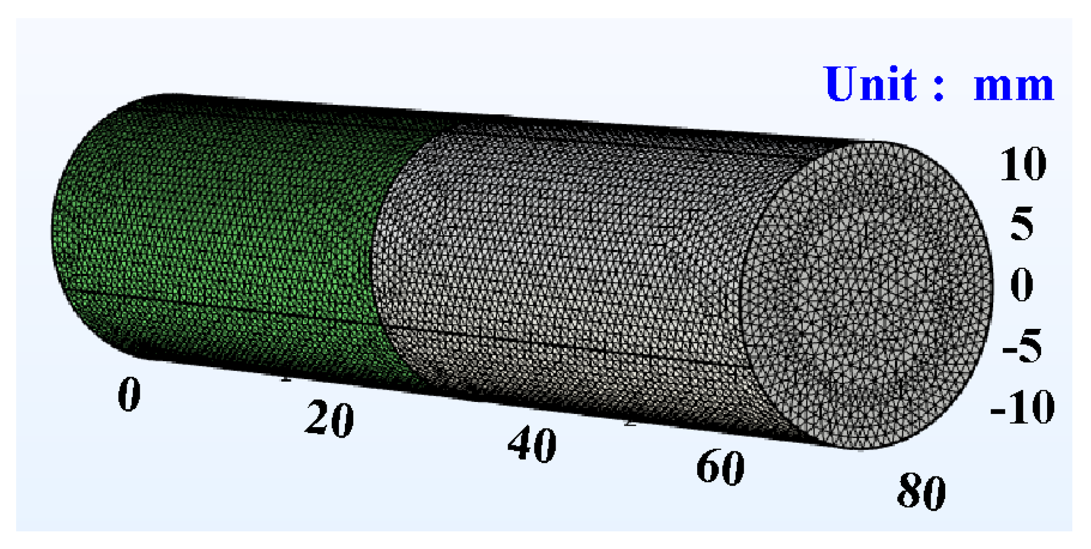
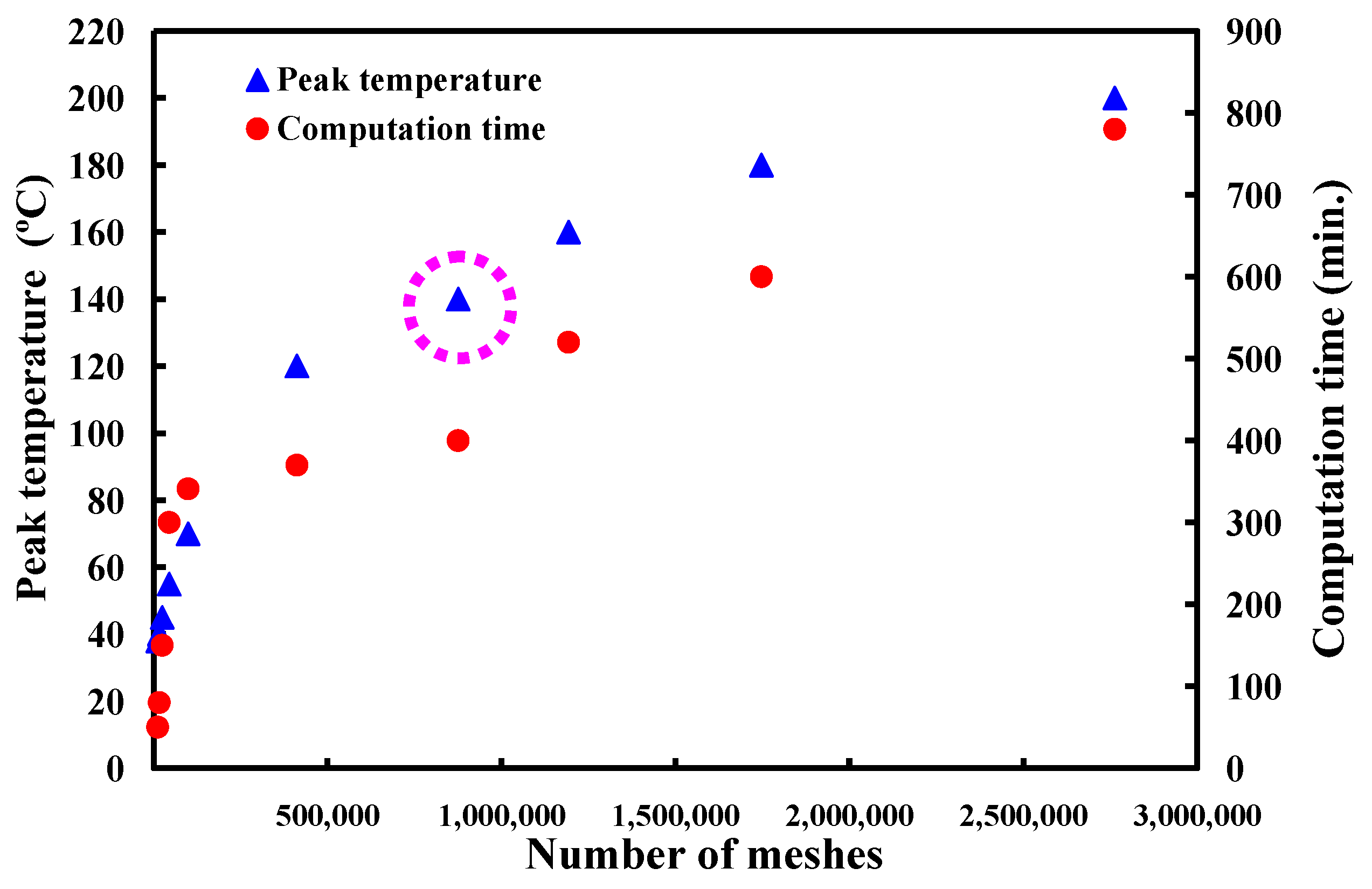
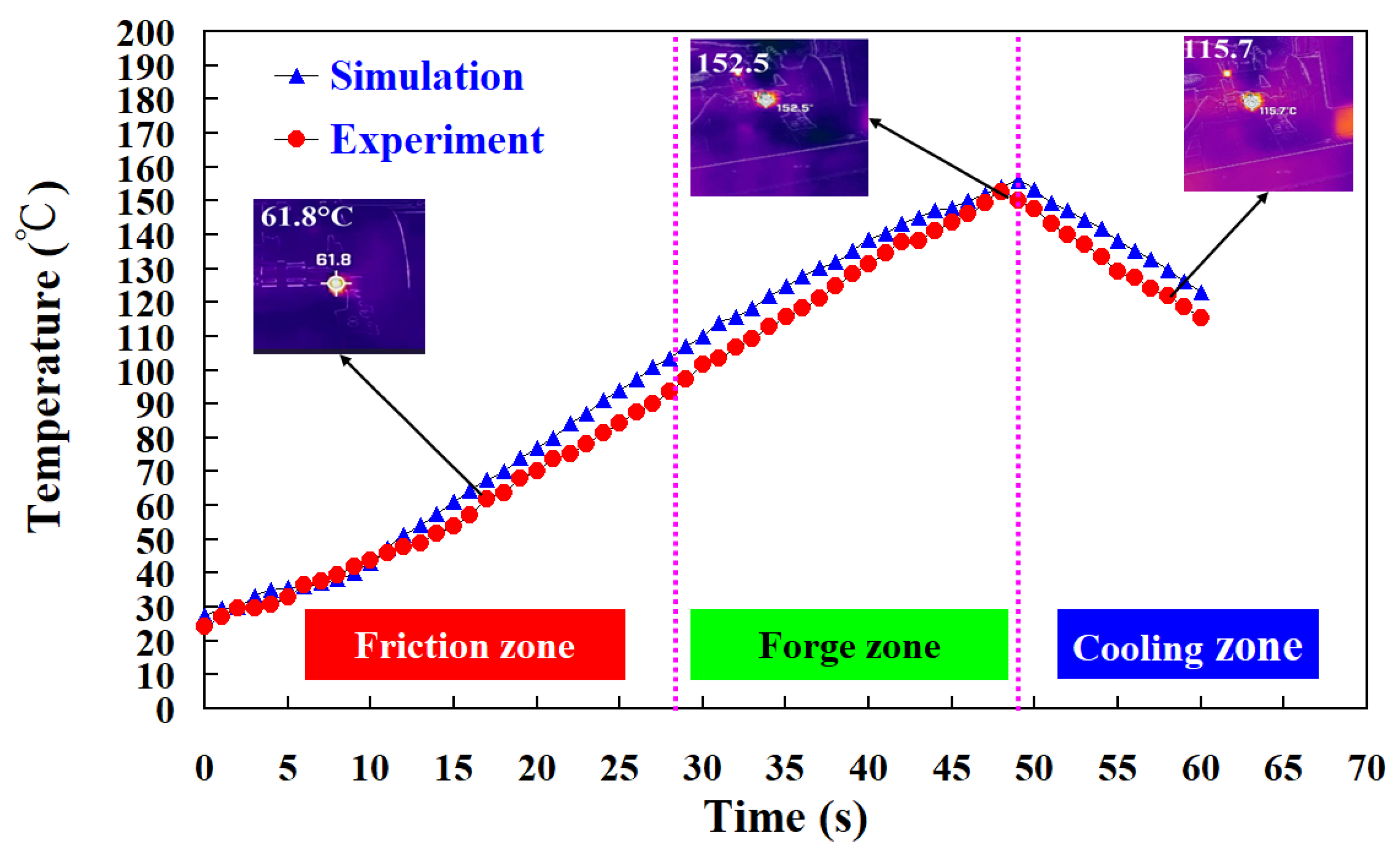
3. Results and Discussion
4. Conclusions
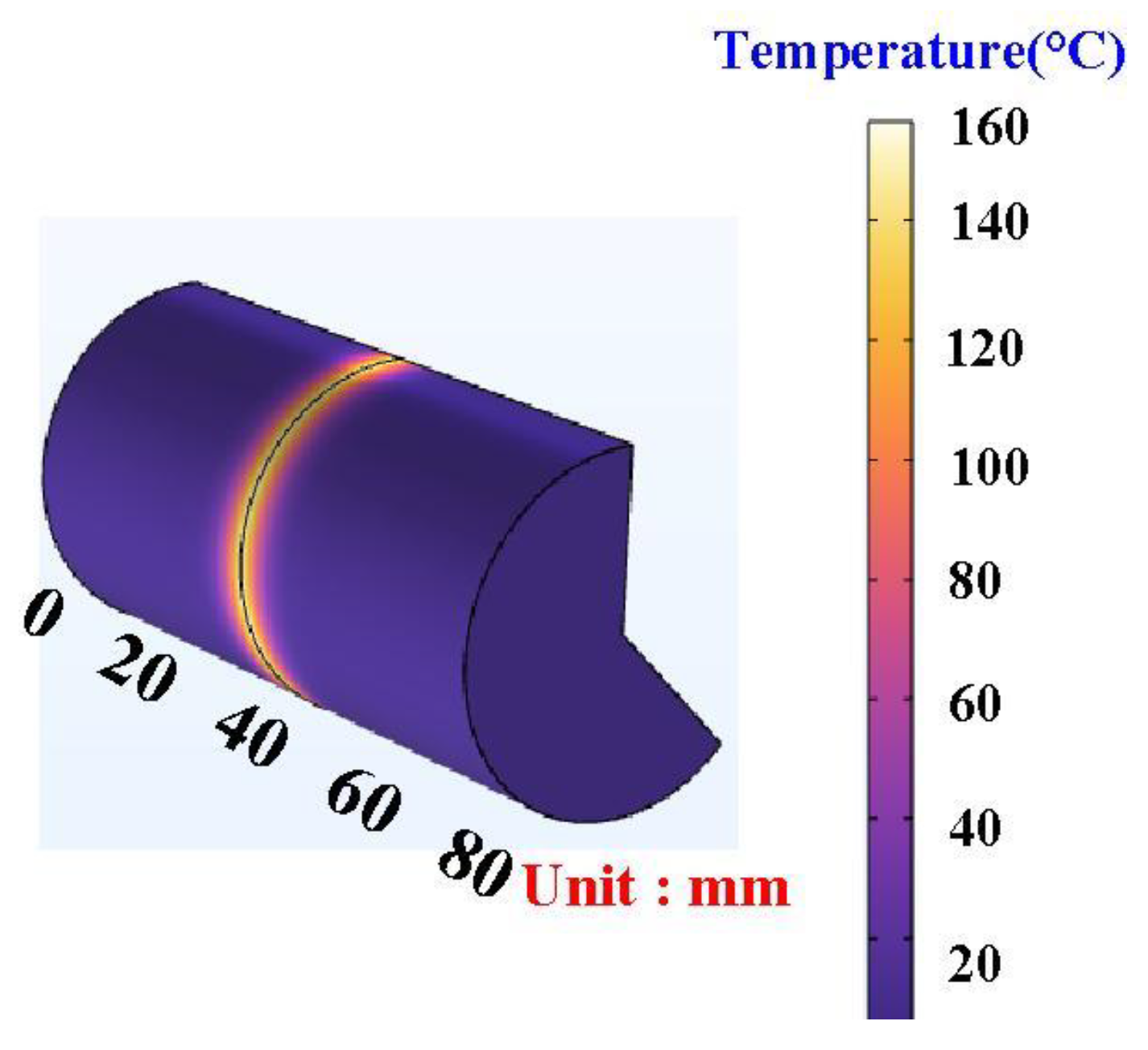
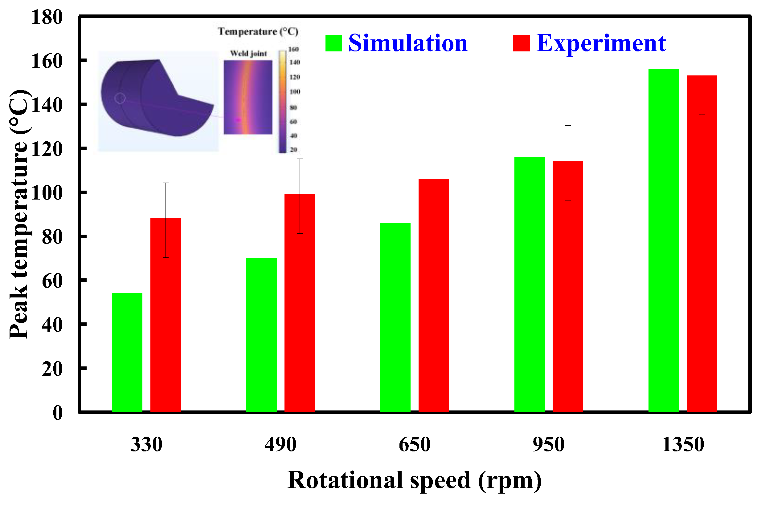
- The use of COMSOL software was feasible for calculating the peak temperature in the weld joint during dissimilar RFW of ABS and PC rods. The mesh element count of 875,688 is the optimal number of meshes for predicting peak temperature in the weld joint. The average error of predicting the peak temperature using the COMSOL software for five different rotational speeds is about 15 °C.
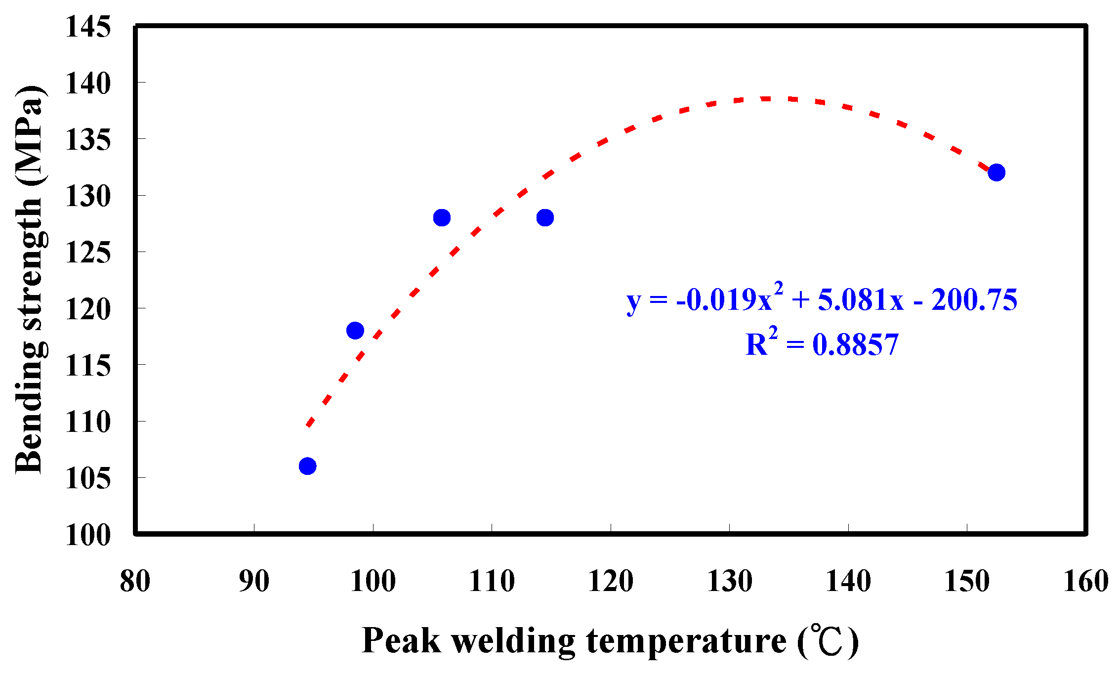
- The bending strength of the welded part (y) using peak welding temperature (x) can be predicted by the equation of y = −0.019 x2 + 5.081x − 200.75 with the correlation coefficient with a correlation coefficient of 0.8857.
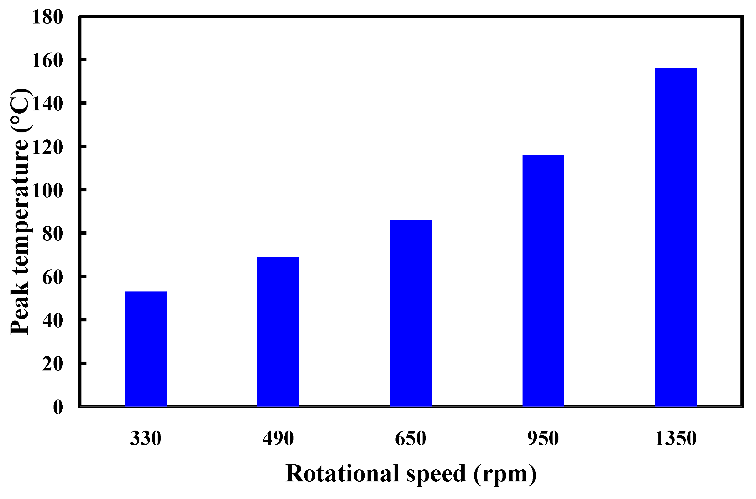
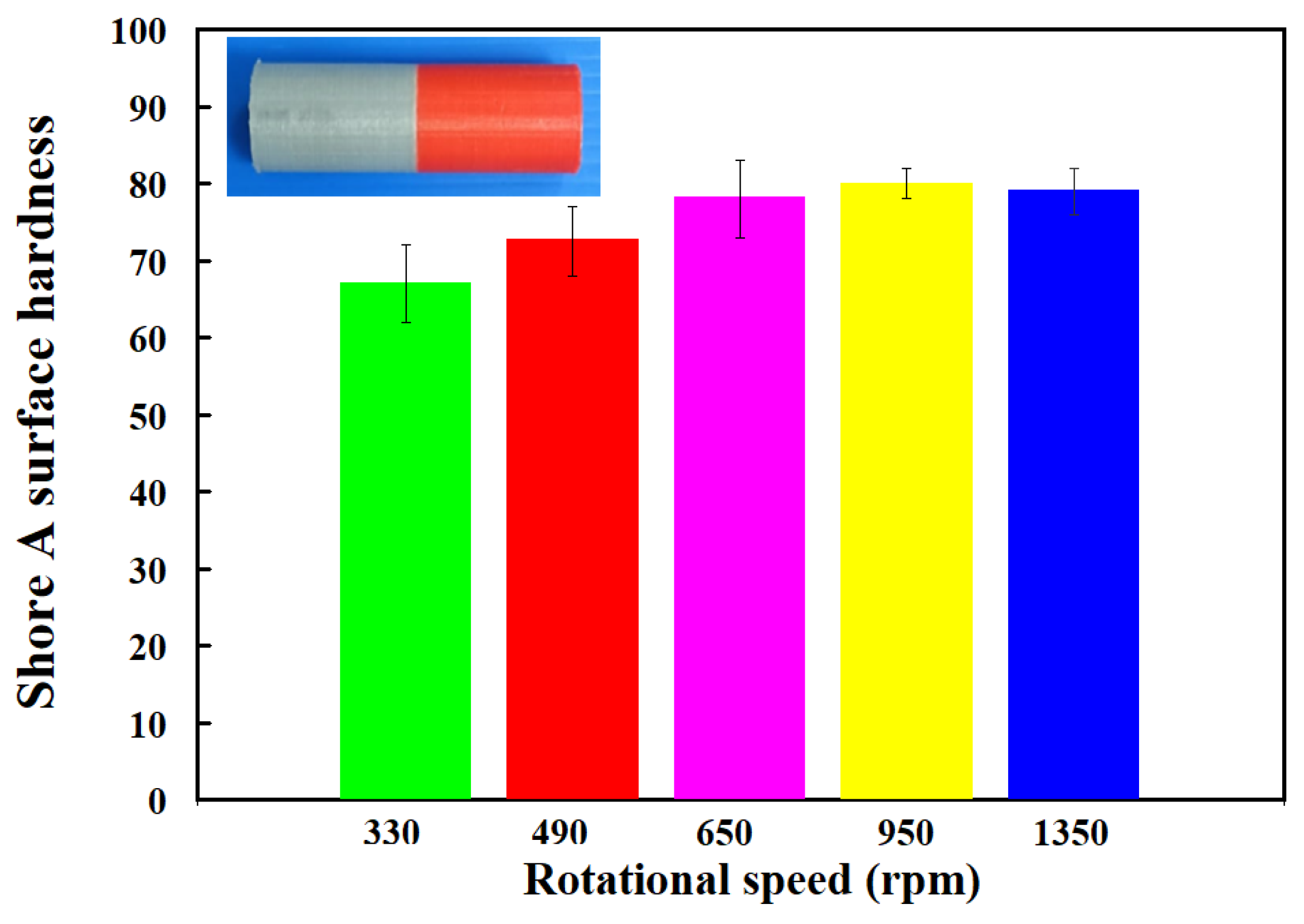
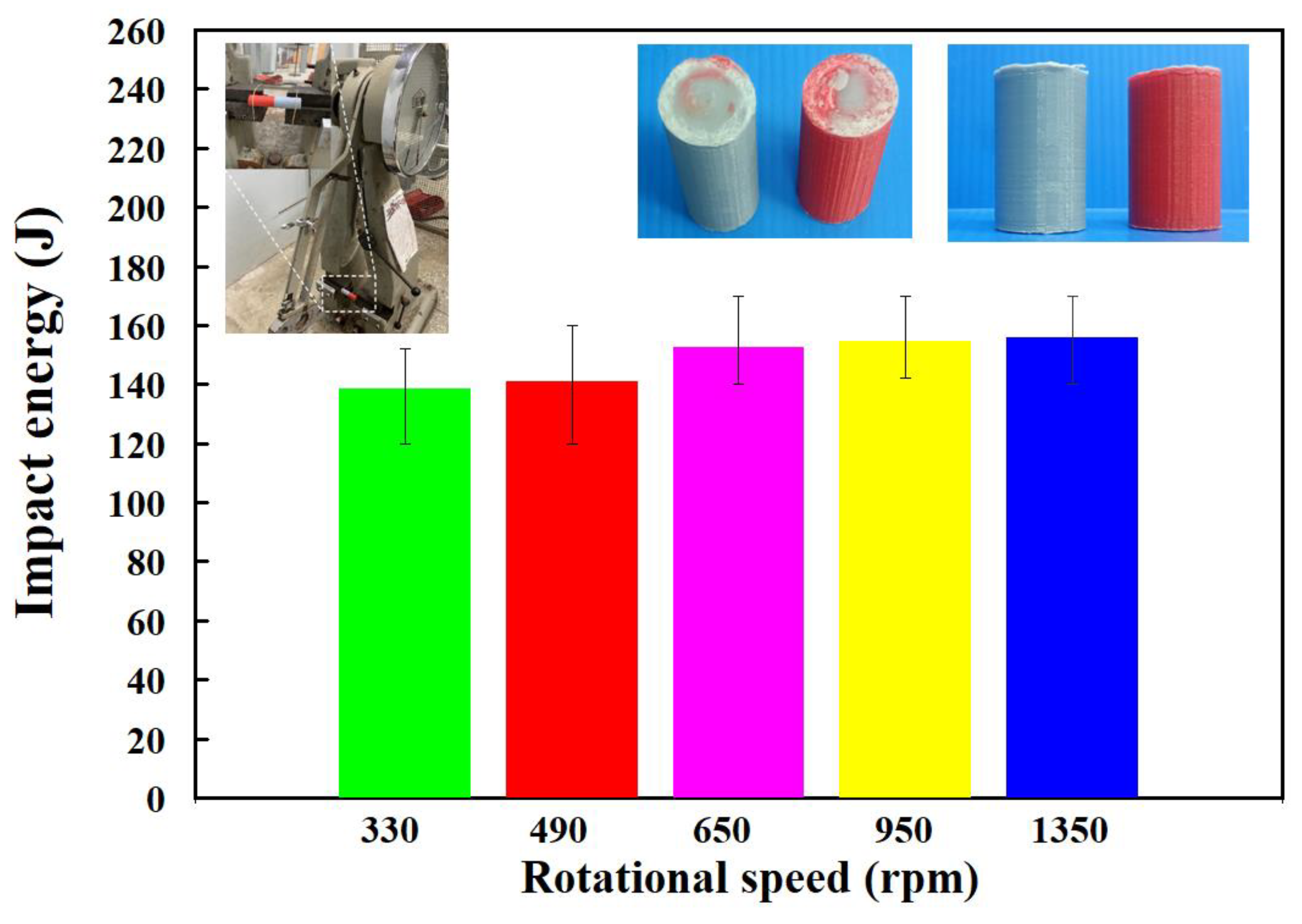
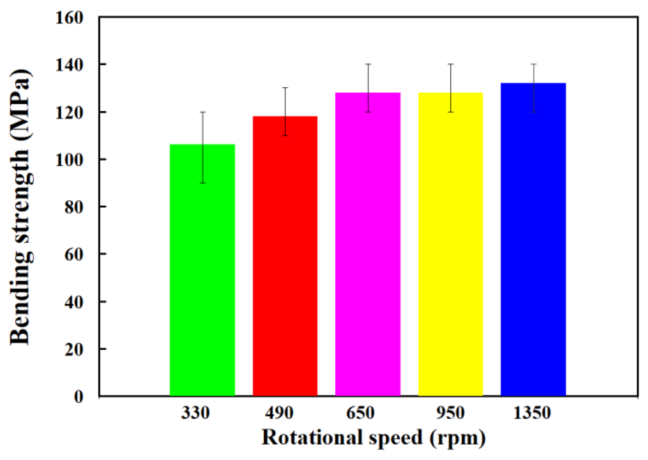
- The bending strength, average shore A surface hardness, and impact energy of the welded parts were increased with increasing the rotational speed of RFW.
Author Contributions
Funding
Institutional Review Board Statement
Data Availability Statement
Conflicts of Interest
References
- Wang, S.; Liang, W.; Duan, L.; Li, G.; Cui, J. Effects of loading rates on mechanical property and failure behavior of single-lap adhesive joints with carbon fiber reinforced plastics and aluminum alloys. Int. J. Adv. Manuf. Technol. 2020, 106, 2569–2581. [Google Scholar] [CrossRef]
- Hamedi, H.; Kamyabi-Gol, A. A novel approach to modelling the bond characteristics between CFRP fabrics and steel plate joints under quasi-static tensile loads. Int. J. Adv. Manuf. Technol. 2021, 116, 3247–3261. [Google Scholar] [CrossRef]
- Yin, P.; Xu, C.; Pan, Q.; Zhang, W.; Jiang, X. Effect of Different Ultrasonic Power on the Properties of RHA Steel Welded Joints. Materials 2022, 15, 768. [Google Scholar] [CrossRef] [PubMed]
- Li, B.; Liu, Q.; Jia, S.; Ren, Y.; Yang, P. Effect of V Content and Heat Input on HAZ Softening of Deep-Sea Pipeline Steel. Materials 2022, 15, 794. [Google Scholar] [CrossRef] [PubMed]
- Lambiase, F.; Grossi, V.; Paoletti, A. Effect of tilt angle in FSW of polycarbonate sheets in butt configuration. Int. J. Adv. Manuf. Technol. 2020, 107, 489–501. [Google Scholar] [CrossRef]
- Delijaicov, S.; Rodrigues, M.; Farias, A.; Neves, M.D.; Bortolussi, R.; Miyazaki, M.; Brandão, F. Microhardness and residual stress of dissimilar and thick aluminum plates AA7181-T7651 and AA7475-T7351 using bobbin, top, bottom, and double-sided FSW methods. Int. J. Adv. Manuf. Technol. 2020, 108, 277–287. [Google Scholar] [CrossRef]
- Hassan, A.J.; Boukharouba, T.; Miroud, D. Concept of forge application under effect of friction time for AISI 316 using friction welding process. Int. J. Adv. Manuf. Technol. 2021, 112, 2223–2231. [Google Scholar] [CrossRef]
- Le, J.; Zhang, H.; Le, M.; Hu, L. Research on identification of the corner point of 90° weld based on multi-sensor signal fusion technology. Int. J. Adv. Manuf. Technol. 2020, 107, 2277–2290. [Google Scholar] [CrossRef]
- Zhang, B.; Shi, Y.; Cui, Y.; Wang, Z.; Chen, X. A high-dynamic-range visual sensing method for feature extraction of welding pool based on adaptive image fusion. Int. J. Adv. Manuf. Technol. 2021, 117, 1675–1687. [Google Scholar] [CrossRef]
- Wu, D.; Wang, H.; Yu, J. Research on machining error transmission mechanism and compensation method for near-net-shaped jet engine blades CNC machining process. Int. J. Adv. Manuf. Technol. 2021, 117, 2755–2773. [Google Scholar] [CrossRef]
- Equbal, A.; Equbal, M.A.; Equbal, M.I.; Ravindrannair, P.; Khan, Z.A.; Badruddin, I.A.; Kamangar, S.; Tirth, V.; Javed, S.; Kittur, M.I. Evaluating CNC Milling Performance for Machining AISI 316 Stainless Steel with Carbide Cutting Tool Insert. Materials 2022, 15, 8051. [Google Scholar] [CrossRef] [PubMed]
- Zhang, D.; Qin, G.; Geng, P.; Ma, H. Study of plastic flow on intermetallic compounds formation in friction welding of aluminum alloy to stainless steel. J. Manuf. Process. 2021, 64, 20–29. [Google Scholar] [CrossRef]
- Ma, X.; Xu, S.; Wang, F.; Zhao, Y.; Meng, X.; Xie, Y.; Wan, L.; Huang, Y. Effect of Temperature and Material Flow Gradients on Mechanical Performances of Friction Stir Welded AA6082-T6 Joints. Materials 2022, 15, 6579. [Google Scholar] [CrossRef] [PubMed]
- Eliseev, A.; Osipovich, K.; Fortuna, S. Gradient Structure of the Transfer Layer in Friction Stir Welding Joints. Materials 2022, 15, 6772. [Google Scholar] [CrossRef]
- Iftikhar, S.H.; Mourad, A.-H.I.; Sheikh-Ahmad, J.; Almaskari, F.; Vincent, S. A Comprehensive Review on Optimal Welding Conditions for Friction Stir Welding of Thermoplastic Polymers and Their Composites. Polymers 2021, 13, 1208. [Google Scholar] [CrossRef] [PubMed]
- Pereira, M.A.R.; Amaro, A.M.; Reis, P.N.B.; Loureiro, A. Effect of Friction Stir Welding Techniques and Parameters on Polymers Joint Efficiency—A Critical Review. Polymers 2021, 13, 2056. [Google Scholar] [CrossRef] [PubMed]
- Wang, G.L.; Li, J.L.; Wang, W.L.; Xiong, J.T.; Zhang, F.S. Rotary friction welding on dissimilar metals of aluminum and brass by using pre-heating method. Int. J. Adv. Manuf. Technol. 2018, 99, 1293–1300. [Google Scholar] [CrossRef]
- Ishraq, M.Y.; Maqsood, S.; Naeem, K.; Abid, M.; Omair, M. Analysing significant process parameters for friction stir welding of polymer composite. Int. J. Adv. Manuf. Technol. 2019, 105, 4973–4987. [Google Scholar] [CrossRef]
- Hangai, Y.; Omika, K.; Inoue, M.; Kitamura, A.; Mitsugi, H.; Fujii, H.; Kamakoshi, Y. Effect of porosity of aluminum foam on welding between aluminum foam and polycarbonate plate during friction welding. Int. J. Adv. Manuf. Technol. 2022, 120, 1071–1078. [Google Scholar] [CrossRef]
- Faes, K.; Dhooge, A.; De Baets, P.; Afschrift, P. New friction welding process for pipeline girth welds—Welding time optimisation. Int. J. Adv. Manuf. Technol. 2009, 43, 982–992. [Google Scholar] [CrossRef]
- Chang, Q.; Gao, P.; Zhang, J.; Huo, Y.; Zhang, Z.; Xie, J. Numerical Simulation of Copper-Aluminum Composite Plate Casting and Rolling Process and Composite Mechanism. Materials 2022, 15, 8139. [Google Scholar] [CrossRef] [PubMed]
- Bochenek, B.; Tajs-Zielińska, K. Cellular Automaton Mimicking Colliding Bodies for Topology Optimization. Materials 2022, 15, 8057. [Google Scholar] [CrossRef]
- Sun, C.; Zhong, C.; Wang, L.; Qin, L. Design and Preparation of Double-Harmonic Piezoelectric Composite Lamination. Materials 2022, 15, 7959. [Google Scholar] [CrossRef] [PubMed]
- Yang, N.; Gong, Y.; He, P.; Zhou, C.; Zhou, R.; Shao, H.; Chen, G.; Lin, X.; Bie, H. Influence of Circular through Hole in Pt–Rh Bushing on Temperature Propagation at High Temperature. Materials 2022, 15, 7832. [Google Scholar] [CrossRef] [PubMed]
- Deng, X.; Li, J.; Xie, X. Effect of Preheating Temperature on Thermal–Mechanical Properties of Dry Vibrating MgO-Based Material Lining in the Tundish. Materials 2022, 15, 7699. [Google Scholar] [CrossRef] [PubMed]
- Jiang, J.; Chen, Q.; Hu, S.; Shi, Y.; He, Z.; Huang, Y.; Hui, C.; Chen, Y.; Wu, H.; Lu, G. Effect of Electro-Thermo-Mechanical Coupling Stress on Top-Cooled E-Mode AlGaN/GaN HEMT. Materials 2023, 16, 1484. [Google Scholar] [CrossRef]
- Nasir, M.H.M.; Taha, M.M.; Razali, N.; Ilyas, R.A.; Knight, V.F.; Norrrahim, M.N.F. Effect of Chemical Treatment of Sugar Palm Fibre on Rheological and Thermal Properties of the PLA Composites Filament for FDM 3D Printing. Materials 2022, 15, 8082. [Google Scholar] [CrossRef]
- Haider, S.M.; Khan, S.A.; Ali, M.A.; Farooq, M.U.; Ishfaq, K. Thermal experiments and analysis on adhesive cleaning of work-holding devices by grinding. Int. J. Adv. Manuf. Technol. 2022, 122, 3849–3865. [Google Scholar] [CrossRef]
- Kuo, C.-C.; Chen, H.-W.; Xu, J.-Y.; Lee, C.-H.; Hunag, S.-H. Effects of Rotational Speed on Joint Characteristics of Green Joining Technique of Dissimilar Polymeric Rods Fabricated by Additive Manufacturing Technology. Polymers 2022, 14, 4822. [Google Scholar] [CrossRef]
- Maier, R.; Istrate, A.M.; Despa, A.; Mandoc, A.C.; Bucaciuc, S.; Stoica, R. Investigation into Thermomechanical Response of Polymer Composite Materials Produced through Additive Manufacturing Technologies. Materials 2022, 15, 5069. [Google Scholar] [CrossRef]
- König, S.; Kreis, P.; Herbert, C.; Wego, A.; Steinmann, M.; Wang, D.; Frank, E.; Buchmeiser, M.R. Melt-Spinning of an Intrinsically Flame-Retardant Polyacrylonitrile Copolymer. Materials 2020, 13, 4826. [Google Scholar] [CrossRef]
- Rajagopalan, S.R.; Lee, B.-Y.; Kang, S.-T. Prediction of the Rheological Properties of Fresh Cementitious Suspensions Considering Microstructural Parameters. Materials 2022, 15, 7044. [Google Scholar] [CrossRef]
- Challa, B.T.; Gummadi, S.K.; Elhattab, K.; Ahlstrom, J.; Sikder, P. In-house processing of 3D printable polyetheretherketone (PEEK) filaments and the effect of fused deposition modeling parameters on 3D-printed PEEK structures. Int. J. Adv. Manuf. Technol. 2022, 121, 1675–1688. [Google Scholar] [CrossRef]
- Zhu, Q.; Yu, K.; Li, H.; Zhang, Q.; Tu, D. Rapid residual stress prediction and feedback control during fused deposition modeling of PLA. Int. J. Adv. Manuf. Technol. 2022, 118, 3229–3240. [Google Scholar] [CrossRef]
- He, X.; Li, L.; He, X.; Xie, C. Multi-Physical Field Simulation of Cracking during Crystal Growth by Bridgman Method. Materials 2023, 16, 3260. [Google Scholar] [CrossRef] [PubMed]
- Yang, F.; Zhang, J.; Guo, C.A.; Zhao, S. Investigation of electrochemical machining for gradual change special-shaped deep spiral hole based on COMSOL. Int. J. Adv. Manuf. Technol. 2020, 108, 2717–2725. [Google Scholar] [CrossRef]
- Reich, M.J.; Woern, A.L.; Tanikella, N.G.; Pearce, J.M. Mechanical Properties and Applications of Recycled Polycarbonate Particle Material Extrusion-Based Additive Manufacturing. Materials 2019, 12, 1642. [Google Scholar] [CrossRef]
- Chua, B.-L.; Baek, S.-H.; Park, K.; Ahn, D.-G. Numerical Investigation of Deposition Characteristics of PLA on an ABS Plate Using a Material Extrusion Process. Materials 2021, 14, 3404. [Google Scholar] [CrossRef] [PubMed]
- Mura, A.; Ricci, A.; Canavese, G. Investigation of Fatigue Behavior of ABS and PC-ABS Polymers at Different Temperatures. Materials 2018, 11, 1818. [Google Scholar] [CrossRef]
- Trivedi, D.N.; Rachchh, N.V. Graphene and its application in thermoplastic polymers as nano-filler—A review. Polymer 2022, 240, 124486. [Google Scholar] [CrossRef]
- Qi, M.; Cao, L.; Zhao, Y.; Jia, F.; Song, S.; He, X.; Yan, X.; Huang, L.; Yin, Z. Quantitative Analysis of Mixed Minerals with Finite Phase Using Thermal Infrared Hyperspectral Technology. Materials 2023, 16, 2743. [Google Scholar] [CrossRef] [PubMed]
- Shrivastava, A.; Krones, M.; Pfefferkorn, F.E. Comparison of energy consumption and environmental impact of friction stir welding and gas metal arc welding for aluminum. CIRP J. Manuf. Sci. Technol. 2015, 9, 159–168. [Google Scholar] [CrossRef]
- Li, K.; Zhou, T.; Liu, B.H. Internet-based intelligent and sustainable manufacturing: Developments and challenges. Int. J. Adv. Manuf. Technol. 2020, 108, 1767–1791. [Google Scholar] [CrossRef]
- Belkahla, Y.; Mazouzi, A.; Lebouachera, S.E.I.; Hassan, A.J.; Fides, M.; Hvizdoš, P.; Cheniti, B.; Miroud, D. Rotary friction welded C45 to 16NiCr6 steel rods: Statistical optimization coupled to mechanical and microstructure approaches. Int. J. Adv. Manuf. Technol. 2021, 116, 2285–2298. [Google Scholar] [CrossRef]
- Barrionuevo, G.O.; Mullo, J.L.; Ramos-Grez, J.A. Predicting the ultimate tensile strength of AISI 1045 steel and 2017-T4 aluminum alloy joints in a laser-assisted rotary friction welding process using machine learning: A comparison with response surface methodology. Int. J. Adv. Manuf. Technol. 2021, 116, 1247–1257. [Google Scholar] [CrossRef]
- Esangbedo, M.O.; Abifarin, J.K. Cost and Quality Optimization Taguchi Design with Grey Relational Analysis of Halloysite Nanotube Hybrid Composite: CNC Machine Manufacturing. Materials 2022, 15, 8154. [Google Scholar] [CrossRef]
- Bouarroudj Eo Abdi, S.; Miroud, D. Improved performance of a heterogeneous weld joint of copper-steel AISI 1045 obtained by rotary friction using a metal powder insert. Int. J. Adv. Manuf. Technol. 2023, 124, 1905–1924. [Google Scholar] [CrossRef]
- Szwajka, K.; Zielińska-Szwajka, J.; Trzepieciński, T. Microstructure and Mechanical Properties of Solid-State Rotary Friction Welded Inconel 713C and 32CrMo4 Steel Joints Used in a Turbocharger Rotor. Materials 2023, 16, 2273. [Google Scholar] [CrossRef]
- Insua, P.; Nakkiew, W.; Wisittipanich, W. Post Weld Heat Treatment Optimization of Dissimilar Friction Stir Welded AA2024-T3 and AA7075-T651 Using Machine Learning and Metaheuristics. Materials 2023, 16, 2081. [Google Scholar] [CrossRef]
- Ahmed, M.M.Z.; Essa, A.R.S.; Ataya, S.; El-Sayed Seleman, M.M.; El-Aty, A.A.; Alzahrani, B.; Touileb, K.; Bakkar, A.; Ponnore, J.J.; Mohamed, A.Y.A. Friction Stir Welding of AA5754-H24: Impact of Tool Pin Eccentricity and Welding Speed on Grain Structure, Crystallographic Texture, and Mechanical Properties. Materials 2023, 16, 2031. [Google Scholar] [CrossRef]
- Pang, Z.; Yang, J.; Cai, Y. Effects of Rotational Speed on the Microstructure and Mechanical Properties of 2198-T8 Al-Li Alloy Processed by Friction Spot Welding. Materials 2023, 16, 1807. [Google Scholar] [CrossRef] [PubMed]
- Dong, J.; Huang, Y.; Zhu, J.; Guan, W.; Yang, L.; Cui, L. Variation Mechanism of Three-Dimensional Force and Force-Based Defect Detection in Friction Stir Welding of Aluminum Alloys. Materials 2023, 16, 1312. [Google Scholar] [CrossRef] [PubMed]


Disclaimer/Publisher’s Note: The statements, opinions and data contained in all publications are solely those of the individual author(s) and contributor(s) and not of MDPI and/or the editor(s). MDPI and/or the editor(s) disclaim responsibility for any injury to people or property resulting from any ideas, methods, instructions or products referred to in the content. |
© 2023 by the authors. Licensee MDPI, Basel, Switzerland. This article is an open access article distributed under the terms and conditions of the Creative Commons Attribution (CC BY) license (https://creativecommons.org/licenses/by/4.0/).
Share and Cite
Kuo, C.-C.; Gurumurthy, N.; Chen, H.-W.; Hunag, S.-H. Experimentation and Numerical Modeling of Peak Temperature in the Weld Joint during Rotary Friction Welding of Dissimilar Plastic Rods. Polymers 2023, 15, 2124. https://doi.org/10.3390/polym15092124
Kuo C-C, Gurumurthy N, Chen H-W, Hunag S-H. Experimentation and Numerical Modeling of Peak Temperature in the Weld Joint during Rotary Friction Welding of Dissimilar Plastic Rods. Polymers. 2023; 15(9):2124. https://doi.org/10.3390/polym15092124
Chicago/Turabian StyleKuo, Chil-Chyuan, Naruboyana Gurumurthy, Hong-Wei Chen, and Song-Hua Hunag. 2023. "Experimentation and Numerical Modeling of Peak Temperature in the Weld Joint during Rotary Friction Welding of Dissimilar Plastic Rods" Polymers 15, no. 9: 2124. https://doi.org/10.3390/polym15092124