1. Introduction
Using the orientation drawing process to obtain oriented films and fibers based on commercially available and cheap polymer grades is considered an interesting scientific direction. However, understanding the mechanisms of the orientation hardening process will allow one to achieve highly oriented polymers with improved mechanical and tribological properties, as well as minimizing the effect of cavitation, which in turn will make it possible to achieve a significant increase in the operational characteristics of polymeric products. Polymers play an important role not only in industrial applications, but also in medical and aerospace applications, particularly when unique tribological properties are required. This is related to their unique properties such as their low cost, easy processing, high corrosion resistance, low friction, and damping of noise and vibrations [
1]. Ultra-high molecular weight polyethylene (UHMWPE) is one of the most important polymers and is used in a lot of applications. UHMWPE in its isotropic state has high wear resistance, a low coefficient of friction, self-lubricating properties, high chemical inertness, good strength, and biocompatible properties [
2,
3,
4,
5,
6]. However, UHMWPE has some critical limitations that do not allow it to be fully used as an engineering material. Bulk UHMWPE with an isotropic structure state has low values of both modulus of elasticity and yield strength, and it exhibits high creep under constant and high loads. In terms of its tribological properties, UHMWPE is superior to nylon and polyformaldehyde, which are widely used in applications requiring a low coefficient of friction [
7,
8,
9,
10]. UHMWPE has a friction coefficient close to that of polytetrafluoroethylene, but UHMWPE surpasses it in wear resistance [
11].
On the other hand, using the drawing and orientation hardening process to enhance the mechanical properties of the UHMWPE and increase its crystallinity can be the most effective way to improve its tribological properties [
12]. Moreover, adding some second-phase particles, which have good tribological properties, into a UHMWPE matrix to form UHMWPE composites can also be an interesting improvement method [
13].
UHMWPE has a high molecular weight of more than 10
6 g/mol, which makes its melt flow index extremely low. This is related to the presence of the entanglements in the UHMWPE amorphous phase in a large number; and they will block the UHMWPE chains’ movement during the drawing process. This obstacle will cause a premature rupture in the UHMWPE macromolecules during the orientation process and prevent obtaining a high degree of effective orientation [
14,
15]. Therefore, adding low molecular weight polyethylene, such as PE-wax, to the UHMWPE matrix will bring down the melt viscosity and facilitate the drawing process of the UHMWPE films [
16,
17]. UHMWPE with a highly oriented structure has excellent mechanical and tribological properties, making it one of the best materials for industrial and medical applications, where high strength and low friction materials are needed [
18,
19]. The oriented films based on the commercial UHMWPE brands are lightweight, with high tensile strength values up to 1.5 GPa, high Young’s modulus values up to 40 GPa, and a highly crystallized structure up to 98% [
17,
20]. Edoumy et al. reported a decrease in wear of the oriented UHMWPE in comparison with the non-oriented UHMWPE when the samples were tested in directions parallel and perpendicular to the UHMWPE chain direction. In dry friction, the UHMWPE chains are oriented on the surface of the sample, which increases the wear resistance of the material. The wear surfaces of the oriented and non-oriented UHMWPE have a wavy morphology. The wavelength is proportional to the thickness of the lamella, which, in turn, decreases with the orientation of the UHMWPE. The friction film thickness is thinner in the case of the oriented UHMWPE [
12]. In reference [
21], they reported that the UHMWPE wear value strongly depends on the type of sliding motions. They found that during unidirectional sliding motion, UHMWPE macromolecules are oriented in the direction of motion. As a result, the UHMWPE surface becomes more durable and wear-resistant. In contrast, during multi-directional sliding motion, the UHMWPE chains had not been arranged, and the orientation processes of macromolecules on the UHMWPE surface were weakly expressed, which explains the increased wear values of the UHMWPE. In reference [
22], they investigated the influence of the UHMWPE molecular orientation on the friction and wear behavior when sliding along the rough surfaces of the counter-faces. They found that, under abrasive conditions as well as in conditions of multidirectional movement, oriented UHMWPE does not have significant advantages in comparison with isotropic UHMWPE. Additionally, Chang et al. reported that the difference in wear resistance between the oriented and the non-oriented UHMWPE was insignificant [
23]. In reference [
24], a wear model was developed that allowed for the study of the changes in the UHMWPE molecular structure under the multidirectional stresses on the articular surface. The authors reported that in the process of the unidirectional motion during friction, the UHMWPE molecular structure will be reorganized under the stress fields. The molecules are stretched along the sliding direction, which leads to hardening of the surface of the polymer. In the case of multidirectional motions, the UHMWPE surface will be softened, and its wear resistance will be decreased.
However, the addition of low molecular weight material, such as PE-wax as an intermolecular lubricant, can improve the mechanical properties of the oriented UHMWPE films obtained by applying the orientation hardening process, but with its effect as a lubricant, it can lead to a reduction in the wear resistance of the films [
25]. Therefore, the addition of friction-reducing material to the oriented UHMWPE, such as carbon fillers, can decrease the friction force and improve the wear resistance of these films [
26,
27,
28,
29,
30]. Moreover, these carbon fillers can facilitate the drawing and orientation processes and increase the maximum obtained draw ratio [
26]. In reference [
27], they reported that the increase in the graphene nanoplatelet (GNP) content in the UHMWPE matrix led to an improvement in the mechanical properties of the UHMWPE/GNP composites, and this led to an improvement in the coefficient of friction and the wear resistance by four times due to the lubrication and toughening effects of the GNP and the easy shear of GNP. They reported that, by adding 1 wt. % of GNP, the tensile strength value was increased from 45 MPa up to 68 MPa in comparison with virgin UHMWPE. This improvement in mechanical properties led to a decrease in wear loss due to lubrication caused by the inter-layer shearing between the GNP layers. In reference [
28], they confirmed that the addition of graphene oxide nanosheets (GO) by 1.0 wt. % led to significantly improving the hardness and wear resistance of the UHMWPE/GO composites, whereas the coefficient of friction was lightly increased. They also reported that the tribological behavior of these composites changed from fatigue wear to abrasive wear after the GO addition. This was related to the formation of a tribolayer on the contact wear surface. In reference [
29], they prepared UHMWPE/GO nanocomposites using two methods. The first one was by the exfoliation of the graphene oxide (GO) in organic solvent and reducing it to graphene before the polymer addition, while the second one was by GO reduction after the polymer addition using the in situ reduction method. They confirmed that UHMWPE/GO films prepared by the pre-reduction method had higher crystallinity, better mechanical properties, and improved creep resistance in comparison with the in situ reduction method and virgin UHMWPE films.
For many years, the cavitation effect was only associated with discontinuity processes in low molecular weight liquids [
31,
32]. The cavitation that occurs in low-molecular weight liquids is affected by the following factors: (a) the magnitude of the resulting tensile stresses and their relationship with the tensile strength of the low-molecular weight liquid itself; (b) the physical and thermodynamic parameters of the liquid; and (c) the presence of cavitation nuclei in the form of vapor bubbles, gases, or solid impurities. In the case of amorphous–crystalline polymers, the phenomenon of the cavitation effect is observed during crystallization from the melt [
33,
34,
35] and during tensile deformation [
36,
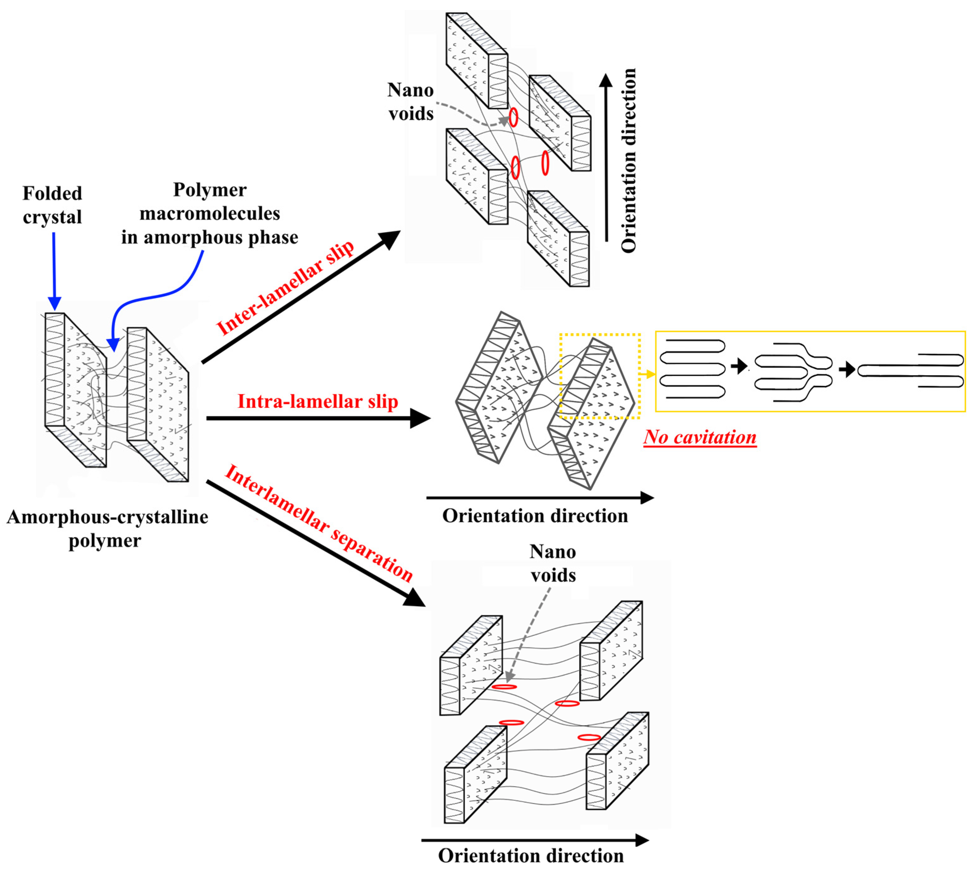
37]. The cavitation effect in amorphous and crystalline polymers is driven by the negative pressure generated in the material, as in low molecular weight liquids. Negative pressure can be generated during the crystallization in areas densely surrounded by growing spherulites, and the cavitation bubbles are mainly observed in these regions. When polymers are stretched, cavities can form in the inter-spherulite regions and inside the spherulites themselves, which makes this phenomenon more intense, and it is initiated at an early stage of deformation (after reaching the yield point). If the deformation of the amorphous–crystalline polymer is accompanied by cavitation, then it is localized in its amorphous phase. In some cases, the properties of the amorphous phase of the polymer at a temperature above its glass transition temperature can be similar to those of low-molecular-weight liquids. The essential difference is the presence of passing macromolecules between crystallites (tie molecules and cilia) and the physical links (entanglements) between macromolecules in the polymer amorphous phase, which significantly limit the mobility of macromolecules. It should be noted that the deformation of amorphous–crystalline polymers occurs in accordance with three main mechanisms: intra-lamellar slip, interlamellar slip, and separation, as well as rotation of lamella stacks [
38,
39]. The deformation caused by the mechanism of intra-lamellar slip occurs only in the crystalline phase of the polymer due to the sliding of folded macromolecules located in crystals along the planes, which leads to the orientation of macromolecules and the formation of a fibrillar structure, which consists of stretching macromolecules in the direction of stretching (
Figure 1). The main feature of this mechanism is the formation of an orientational crystal structure without the effect of cavitation, i.e., without the formation of voids in the amorphous phase of the oriented polymer. The deformation of the amorphous–crystalline polymer by the mechanisms of inter-lamellar slip and separation leads to the formation of a cavitation effect. These mechanisms lead to a change in the distances between adjacent lamellae when the direction of applied tensile stress is perpendicular to the lamella surface (
Figure 1). The intensity of the flow of polymer deformation by the mechanism of inter-lamellar slip is influenced by the material’s structure, particularly the number and distribution of tie macromolecules between crystallites, as well as the size of the crystalline phase. As a result of the lamellae separation in the volume of the elongated polymer, an intensive process of void formation will occur [
40]. It should be noted that, for materials that are characterized by a relatively high modulus of elasticity and the ability to undergo significant plastic deformation (UHMWPE and high-density polyethylene), the process of separation of lamellae is accompanied by local changes in the density of the sample, the result of which is the formation of material inhomogeneity (voids). Visually, this effect is expressed in a strong whitening of the sample upon reaching high degrees of drawing. In references [
41,
42], the authors demonstrated a strong dependence of the manifestation of the cavitation effect on the strain rate for isotactic polypropylene. As the strain rate increases, so do the stresses at which the polymer reaches its yield strength. This means that the crystalline phase is subjected to high stresses, which increase the cavitation effect. It was noted in reference [
43] that the increase in the molecular weight of a polymer promotes an increase in the density of the physical entanglements of macromolecules. Physical links (entanglements) in the amorphous phase are considered a reinforcing element that increases the strength of the amorphous phase and, therefore, reduces the effect of cavitation. In addition, the deformation of polymers with large, strong, and defect-free crystals, such as polypropylene (PP), high-density polyethylene (HDPE), and UHMWPE, is accompanied by intense cavitation processes. If the polymer has a finely crystalline and defective structure, such as low-density polyethylene (LDPE), deformation occurs with significantly less cavitation. This is because the plastic deformation of small and defective crystals begins at lower stresses, which do not exceed the strength of the amorphous phase [
44]. This means that cavitation is more intense in polymers with high crystalline strength because most of the applied stresses in the orientation process are transferred to the amorphous phase [
44]. The type of applied stress (tension, compression, or shear) on the polymer plays a key role in the appearance of cavitation [
45]. Under uniaxial tension, the deformation of the crystalline phase is predominantly carried out by the mechanism of interlamellar slip, which is accompanied by rupture and slip of macromolecules in the amorphous phase. Under compressive and shear stresses, the deformation of the crystalline phase mainly occurs according to the mechanism of intra-lamellar slip, and the orientation of macromolecules occurs without the formation of any cavities.
It should be noted that, in our previous article [
20], the used UHMWPE had a molecular weight of 10
6 g/mole and was considered a special grade compared to the available commercial grade that was used in this article (GUR 4120). This lower molecular weight makes the processing of the polymer and orientation hardening easier in comparison with other UHMWPE grades, such as the UHMWPE grade used in this article, which has an average molecular weight of 5 × 10
6 g/mol. This difficulty in the orientation process using a UHMWPE grade with a high molecular weight is related to the presence of a large number of entanglements in the UHMWPE amorphous phase, which blocks the UHMWPE chains’ movement during the orientation process, as was mentioned above. This will cause a high level of stress on the polymer macromolecules in the amorphous phase, leading to their premature rupture during the orientation process. On the other hand, the role of the carbon fillers in the highly oriented polymeric films on cavitation is weakly studied in the published articles. Currently, and based on the above-mentioned literature review, the majority of published articles investigated the influence of carbon fillers on the mechanical and tribological properties of polymers with an isotropic structure, with a few investigating this influence on polymers with an oriented structure. However, all published articles are deficient in discussing the mechanical and tribological properties of oriented polymer/carbon filler films in terms of structure and cavitation. Therefore, in this article, we tried to focus on these points.
This work is aimed at studying the influence of GNP/PANI addition on the oriented macromolecular structure, cavitation, and mechanical properties of the UHMWPE composites with PE-wax and the influence of GNP/PANI addition on the tribological properties of the UHMWPE films.
3. Results and Discussion
As it can be seen in
Table 3 and
Table 4, with the increase in GNP/PANI content, the mechanical properties of oriented UHMWPE films obtained by both thermal orientation regimes decreased. For the oriented UHMWPE/PE-wax/GNP/PANI films obtained by the first thermal orientation regime, the best tensile strength value was 1080 MPa, which was obtained at a GNP/PANI content of 0.01 wt. %; the best Young’s modulus value was 33.8 GPa, which was obtained at a GNP/PANI content of 4.0 wt. %; and the best work of fracture value was 40.24 MJ/m
3, which was obtained at a GNP/PANI content of 1.0 wt. %. Whereas, for the UHMWPE/PE-wax/GNP/PANI films obtained by the second thermal orientation regime, the best mechanical properties were obtained at a GNP/PANI content of 2.0 wt. %. The UHMWPE/1.0 wt. % PE-wax/2.0 wt. % GNP/PANI films had a tensile strength value of 1000 MPa, a Young’s modulus value of 32.1 GPa, and a work of fracture value of 49.24 MJ/m
3. This decrease in the mechanical properties of oriented UHMWPE films is associated with the intensification of the cavitation process. However, it should be noted that the tensile strength values of the UHMWPE/PE-wax/GNP/PANI films for each GNP/PANI content were very similar for both used thermal regimes, whereas the Young’s modulus values of these films obtained by the first thermal regime were significantly higher than the ones obtained by the second thermal regime. These high Young’s modulus values are related to the higher draw ratio values for the films obtained by the first thermal regime.
It was also found that the increase in the content of GNP/PANI up to 2.0 wt. % leads to an almost two-fold increase in the maximum draw ratio of UHMWPE films in comparison with oriented-virgin UHMWPE and UHMWPE/PE-wax films for both thermal orientation regimes (
Figure 5). During solid-phase mixing in the planetary ball mill, GNP/PANI are distributed over the surface of the UHMWPE particles, and each UHMWPE particle can then give a separate microfibril during the thermal orientation process. Due to the presence of GPN/PANI on the surface of UHMWPE particles between fibrils during the thermal orientation process, interfibrillar sliding with intensive fibrillation can occur, which increases the final draw ratio of the films, but is not accompanied by an increase in strength properties. Moreover, GNP/PANI agglomerates were not observed in the UHMWPE matrix (
Figure S5).
Moreover, for the films prepared based on the first thermal regime, it was found that the addition of GNP/PANI resulted in an increase in total cavitation area with increasing GNP/PANI content compared to the oriented-virgin UHMWPE and UHMWPE/PE-wax films, resulting in an increase in the maximum obtained draw ratio. An increase in the total cavitation area by 120–320% with an increase in the GNP/PANI content in comparison with oriented-virgin UHMWPE and UHMWPE/PE-wax films is shown in
Figure 6 (also
Figures S6–S8 and S10). Moreover, the addition of GNP/PANI leads to a significant increase in pore sizes by 300–400% compared to oriented-virgin UHMWPE films, and this increase in pore sizes has occurred by increasing the GNP/PANI content and by increasing the draw ratio.
As it can be seen in
Table 3 and
Table 4, the virgin-oriented UHNWPE and UHMWPE/PE-wax films had almost the same draw ratio values for both applied thermal regimes. Therefore, in order to better understand the role of the draw ratio on the structure and cavitation process of the UHMWPE/PE-wax/GNP/PANI, the films obtained by the second thermal regime (with a lower draw ratio in comparison with the films obtained by the first regime) with GNP/PANI contents of 0.01 and 2.0 wt. % were investigated and compared with the films that have the same GNP/PANI contents. As it can be seen in
Figure 7 (also
Figures S9 and S11), the cavitation area and pore size were smaller for the UHMWPE/PE-wax/GNP/PANI films obtained by the second thermal regime in comparison with the films obtained by the first thermal regime. These results are related to the lower draw ratio of the films that were prepared based on the second thermal regime, which means a lower fibrillation process in comparison with the films obtained by the first thermal regime.
The intensification of cavitation processes upon the addition of the GNP/PANI to the UHMWPE matrix is associated with a deterioration in the diffusion of macromolecules between UHMWPE particles during the preparation of the UHMWPE xerogels. In the oriented UHMWPE films filled with GNP/PANI, the bond between microfibrils will be worse compared to that in oriented virgin UHMWPE films. When the tensile stresses are applied in the orientation process, the microfibrils in the transverse direction are more easily separated from each other, which leads to the intensification of cavitation processes.
The appearance of an elastic modulus plateau at temperatures above the polymer’s melting point is associated with a high density of physical links (entanglements or crosslinks) between polymer macromolecules, which can retain elastic properties in the material after melting the crystalline phase [
53]. Sliding of UHMWPE macromolecules inside the material at the GNP/PANI interfaces is confirmed by DMA studies, in which the appearance of the plateau of the elastic modulus of UHMWPE xerogels in the melting temperature region, is related to the presence of the entanglements (
Figure 8). For isotropic UHMWPE and UHMWPE/1%PE-wax xerogels at a temperature of 150 °C, the elastic modulus reaches a plateau, which is associated with a high density of physical entanglements between UHMWPE macromolecules, which retain the elastic properties in the material after melting of the crystalline phase [
53,
54]. For the UHMWPE xerogels with GNP/PANI contents of 0.01 and 2.0 wt. %, the modulus of elasticity drops to zero at 150 °C. The reason for this may be the intense internal slippage of the material over surfaces saturated with GNP/PANI and containing a low density of transverse (tie) macromolecules.
Table 5 and
Table 6 show the DSC test results for the UHMWPE/1.0 wt. % PE-wax/GNP/PANI films obtained by both thermal orientation regimes. As it can be seen in these tables, the obtained UHMWPE/1.0 wt. % PE-wax/GNP/PANI films had high crystallinity values because of the orientation process of the UHMWPE macromolecules and the transformation of the lamellae to fibrillar structure (recrystallization), which in turn leads to a reduction of the defects of the crystalline phase [
55]. It is related to the presence of the PE-wax as an intermolecular lubricant, which promotes recrystallization processes as a result of the greater mobility of the UHMWPE macromolecules. For the UHMWPE/1.0 wt. % PE-wax/GNP/PANI films obtained by the first thermal orientation regime, the influence of the GNP/PANI addition on the melting temperature was not observed; but, for the films obtained by the second one, the melting temperature values of the UHMWPE/1.0 wt. % PE-wax/GNP/PANI films were increased.
The behavior of the friction coefficient is determined by the adhesive and deformation components. The adhesive component is associated with intermolecular interactions on friction surfaces, which can be different in nature. Intermolecular interactions exist not only in places of direct contact between rubbing surfaces, but also at some distances where there is no direct contact. The deformation component arises because of the bulk deformation of the friction surfaces, which leads to the penetration of the surface of a more rigid material into a softer one, an increase in the contact friction area, and an increase in the roughness of the friction surfaces. The embedded element, moving in the tangential direction, either deforms the surface of a softer material, or cuts it off. The role of these two types of friction coefficient components depends on the conditions under which friction occurs. For example, an increase in the applied load leads to an increase in plastic deformation, which, in turn, leads to an increase in the deformation component. On the other hand, an increase in load leads to a decrease in the adhesive component while maintaining surface roughness because of the increase in shear stresses that destroy molecular bonds. Thus, considering the role of each component in a particular friction unit, it is possible to minimize the values of the friction coefficient [
56].
Figure 9 and
Figure 10 and
Table 7 present the results of tribological tests demonstrating the effect of draw ratio, PE-wax, and GPN/PANI content on friction coefficient and wear resistance for the films obtained by the first thermal orientation regime. The change in the friction coefficient for all tested materials occurred in two stages, as follows: Stage 1–increasing the coefficient of friction at the beginning of the test as the surface adapts to wear; Stage 2–the friction coefficient reaches a plateau due to the formation of a tribo-layer, which helps to reduce friction, which in turn reduces abrasive wear and the deformation component of the friction coefficient [
57,
58].
For isotropic UHMWPE, when a high load (30 N) was applied, the friction coefficient tended to gradually increase and stabilize at 0.269. The appearance of the orientation of UHMWPE macromolecules leads to a significant decrease in the friction coefficient from 0.269 for isotropic UHMWPE to 0.179 for oriented UHMWPE. The decrease in the friction coefficient is associated with an increase in the mechanical properties of UHMWPE because of the thermal orientation hardening process, which increases the rigidity of the material and reduces the deformation component of the friction coefficient (reducing the penetration of the counter-body into the surface of the material under test) [
21,
22,
23,
24]. The addition of the PE-wax contributes to an additional reduction in the initial moment of the coefficient of friction due to its action as a lubricant and an increase in the mechanical properties of the UHMWPE/PE-wax films. Increasing the time of the friction test led to an increase in the coefficient of friction up to 0.171 (near the COF value of the oriented virgin UHMWPE films), due to a change in the surface roughness of the UHMWPE/PE-wax films. The addition of GNP/PANI antifriction particles to the UHMWPE matrix contributed to an additional reduction in the friction coefficient and an increase in wear resistance (
Figure 9 and
Figure 10, and
Table 7) due to the lubricating effect of carbon materials. GNP/PANI reduce the coefficient of friction from 0.179 to 0.122 for the films with a content of GNP/PANI of 2.0 wt. % [
27,
28,
29].
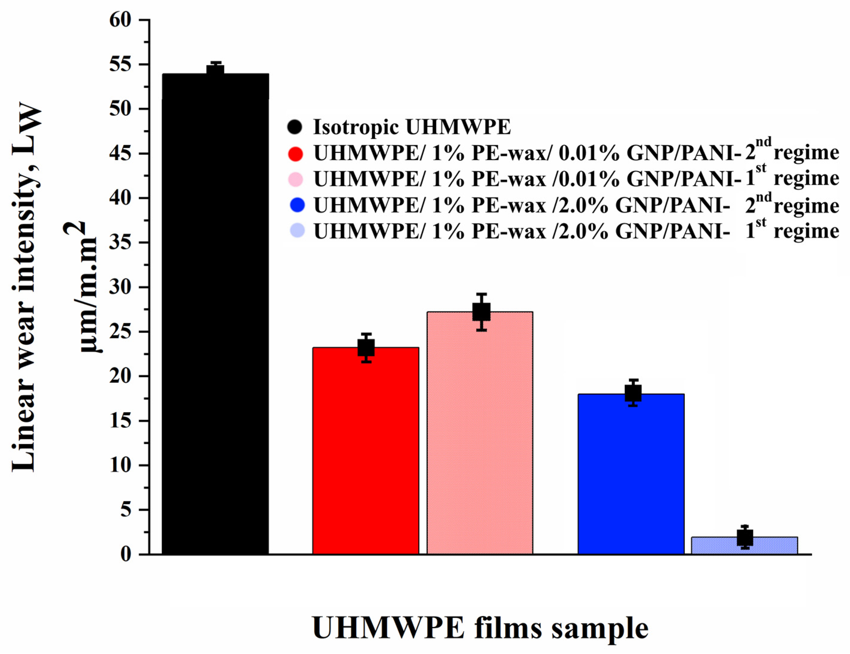
From
Figure 10, the appearance of orientation in the UHMWPE macromolecules leads to a slight decrease in wear in comparison with the isotropic UHMWPE. With the addition of PE-wax, wear is reduced from 45.63 µm/m.m
2 for the oriented virgin UHMWPE films to 21.83 µm/m.m
2 for UHMWPE/PE wax films, by improving the mechanical properties and increasing the material stiffness as a result of the thermal orientation stretching process. Because GNPs are highly abrasion resistant, increasing the GNP/PANI content results in an additional reduction in wear values. A minimum wear value of 1.92 µm/m.m
2 was obtained for oriented UHMWPE/PE-wax/GNP/PANI films with a GNP/PANI content of 2.0 wt. % obtained by the first thermal orientation regime. From
Table 7, the content of GNP/PANI greater than 2 wt. % did not have a positive effect on the values of the coefficient of friction and wear resistance due to a decrease in the maximum draw ratio of the films [
27,
59,
60].
Figure 11 shows the SEM micrographs of the friction surfaces of UHMWPE samples before and after tribological tests. The movement of the counter-body in one direction during tribological tests leads to the appearance of an oriented structure on the surface of isotropic UHMWPE. On the other hand, on the surfaces of the oriented UHMWPE and UHMWPE/PE-wax films, traces of strong abrasive wear and waves oriented perpendicular to the direction of friction were found. During long-term operation of oriented UHMWPE and UHMWPE/PE-wax films, fatigue wear mechanisms will occur. Microstructural changes recognized with frictional loading are a precursor to the formation of fatigue microcracks on the friction surface (
Figure 11). This process is characterized by the formation of cracks on the polymer surface, which cause delamination and the formation of large wear particles [
12,
61]. Moreover, it was found that the presence of GNP/PANI leads to a reduction in fatigue and a significant reduction in cracks. The positive effect of GNP/PANI can be caused by the uniform distribution of GNP/PANI in the UHMWPE matrix and the formation of a tribolayer with a lubricating effect on the surface of oriented UHMWPE films. As can be seen in
Figure 11, minimal damage to the friction surface occurs for UHMWPE/PE-wax/GNP/PANI films at GNP/PANI content of 2.0 wt. %.
Once again, in order to better understand the role of the draw ratio on the tribological properties of the UHMWPE/PE-wax/GNP/PANI, the films obtained by the second thermal regime with GNP/PANI contents of 0.01 and 2.0 wt. % were investigated and compared with the films that have the same GNP/PANI contents. As can be seen in
Table 8 and
Figure 12 and
Figure 13, for the UHMWPE/1.0% PE-wax/GNP/PANI films with a GNP/PANI content of 0.01 wt. % obtained by the first and second thermal orientation regimes, the COF and linear wear intensity values were not changed by increasing the draw ratio (DR) values. Since the mechanical properties and the crystallinity of these films are very similar, this small amount of GNP/PANI leads to an improvement in the DR values, but does not improve the tribological properties. On the other hand, for the UHMWPE/1.0% PE-wax/GNP/PANI films with a GNP/PANI content of 2.0 wt. %, both COF and linear wear intensity values were significantly improved when the DR value was increased. Because the mechanical properties and crystallinity of these films are so similar, this improvement can be attributed to the high DR value and sufficiently high GNP or PANI content.
4. Conclusions
The influence of the GNP/PANI addition to the UHMWPE matrix on the structure, formation of voids (cavitation process), mechanical, and tribological properties was studied for the highly oriented UHMWPE films. A thermal orientation process was used to prepare highly oriented UHMWPE films. The findings indicated that the increase in the content of GNP/PANI up to 2.0 wt. % had led to an increase in the maximum draw ratio of UHMWPE films by approximately two times in comparison with the oriented virgin UHMWPE films. The explanation could be as follows. The interfibrillar sliding during the intensive fibrillation process during the thermal orientation process led to an intensification of the cavitation processes, which in turn led to a decrease in the mechanical properties of the highly oriented UHMWPE/PE-wax/GNP/PANI films. In comparison with the oriented-virgin UHMWPE films, SEM micrographs revealed an increase in total cavitation area of 120–320% and pore size of 300–400% by the increase in GNP/PANI content. Based on DMA tests for UHMWPE xerogels, the appearance of the elastic modulus plateau in the melting temperature region was confirmed, indicating the sliding of the UHMWPE macromolecules inside the material at the GNP/PANI interfaces, which could be related to the intense internal slippage in the material over surfaces saturated with GNP/PANI and containing a low density of transverse (tie) macromolecules.
The influence of each component in the oriented UHMWPE films can be distinguished based on the results of the tribological tests as follows:
PE-wax functions as a lubricant with a low molecular weight.
In comparison to isotropic UHMWPE, the thermal orientation drawing process increases mechanical properties, which increases material rigidity and reduces the deformation component of the friction coefficient (reducing counter-body penetration into the surface of the material being tested).
In the process of the friction in the surface layers of the polymer matrix involved in the friction, an intense movement of the macromolecules is observed, aimed at reorienting the polymer chains in the direction of the friction. The reduction of the shear deformations for the oriented films is related to the fact that the reorientation of the UHMWPE macromolecules is not required, which in turn leads to a decrease in the coefficient of friction.
The fibrillar structure of the oriented films contributes to an increase in the resistance to fatigue strength during friction.
GNP has a high resistance to abrasive wear, which means that incorporating GNP/PANI into the polymer matrix reduces overall composite wear.
Based on the obtained UHMWPE films, the best ones are UHMWPE/PE-wax/GNP/PANI films with a GNP/PANI content of 2.0 wt. %. They have excellent mechanical and tribological properties in terms of tensile strength of 836 MPa, Young’s modulus of 35.8 GPa, and COF of 0.122. These films have a high crystallinity of 87%, but their cavitation area is also high (42%), and their average pore size is 3.7 ± 0.4 µm, which explains the decrease in their tensile strength in comparison with UHMWPE/PE-wax films.
Finally, these highly oriented UHMWPE/PE-wax/GNP/PANI films with excellent mechanical and tribological properties are prepared from cheap large-scale grades of UHMWPE. Therefore, they are considered the best choice for both biomedical and industrial applications, especially tribological applications (sliding bearings). They can be widely used as materials that form the friction surface, such as coatings for plain bearings, various guides, and rollers operating under hard, dry friction conditions.


 ,
, 


