Strength Degradation in Curved Fiber-reinforced Polymer (FRP) Bars Used as Concrete Reinforcement


Abstract
:
1. Introduction
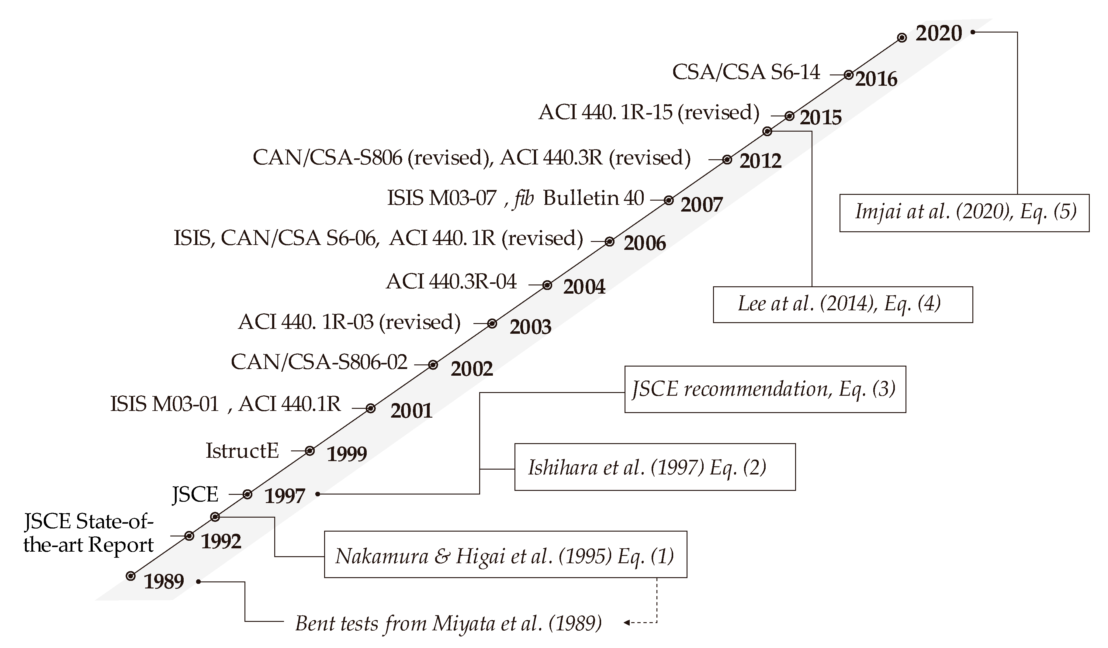
2. Research on the Strength Degradation of Curved FRPs
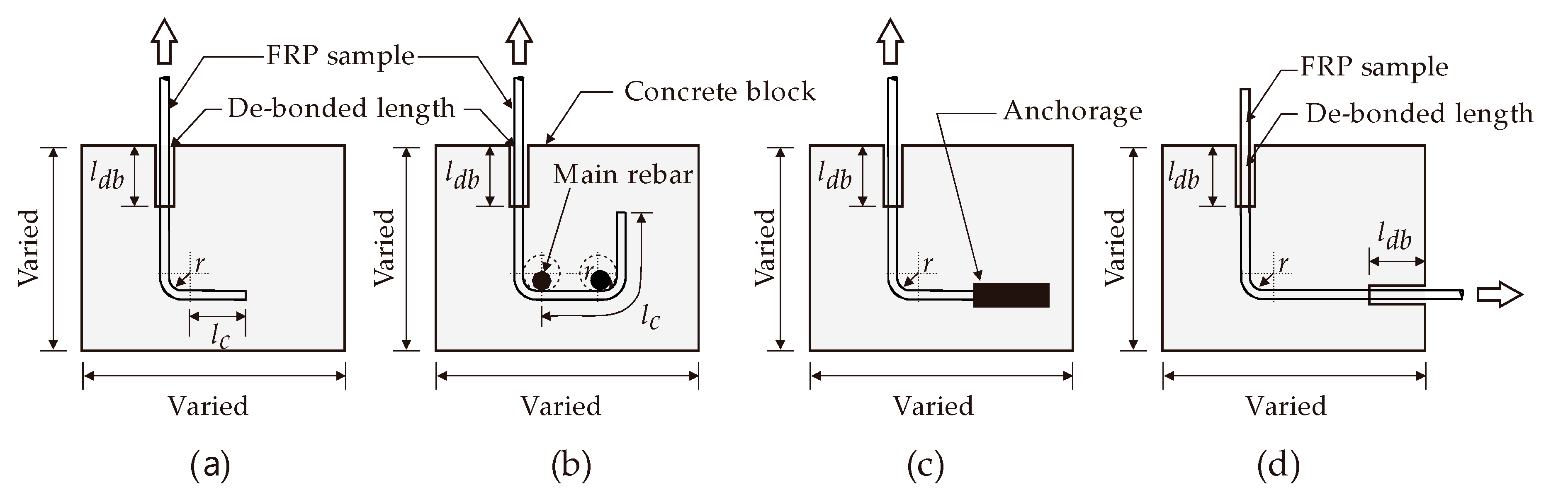
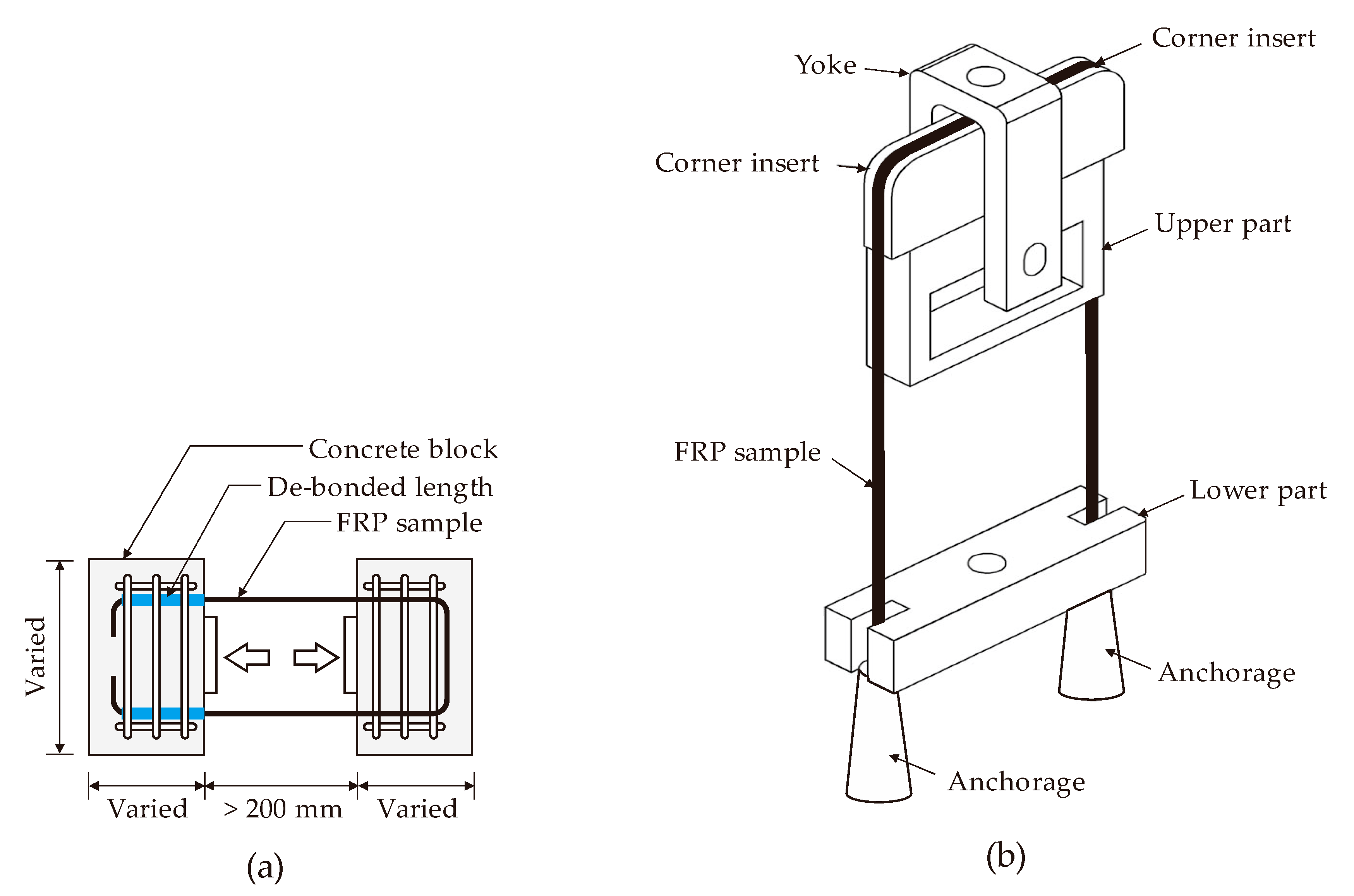
3. ACI Testing Methods to Determine the Bend Capacity of FRP Reinforcements
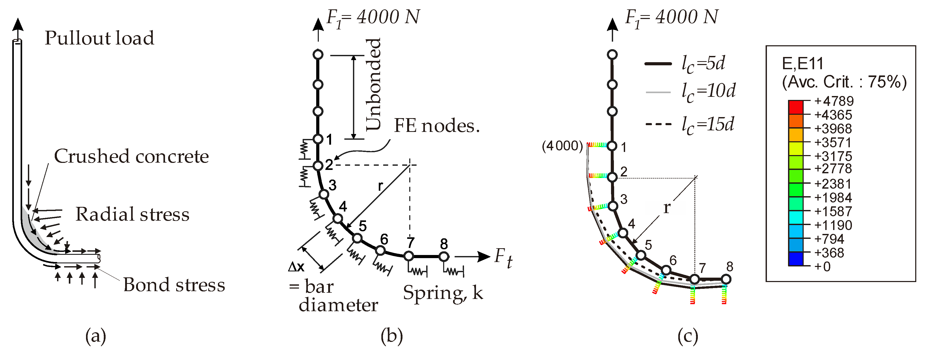
4. Models to Assess the Bend Capacity of FRP Reinforcements
5. Prefabricated FRP Composites and Future Challenges
6. Concluding Remarks
Author Contributions
Funding
Acknowledgments
Conflicts of Interest
Abbreviations
| ACI | American Concrete Institute |
| AFRP | Aramid Fiber-reinforced polymer |
| BS | British Standard |
| BSI | British Standard Institute |
| CEB | Comit Euro-international du Beton |
| CEN | Comite Europeen de Normalisation |
| CFCC | Carbon Fiber Composite Cable |
| CFRP | Carbon Fiber-reinforced polymer |
| EC | Eurocode |
| FEA | Finite Element Analysis |
| FIB | Federation Interationale du Beton |
| FRP | Fiber-reinforced polymer |
| GFRP | Glass Fiber-reinforced polymer |
| ISE | Institution of Structural Engineering |
| ISIS | Intelligent Sensing for Innovative Structures |
| JSCE | Japanese Society of Civil Engineers |
| NFR | Non-Ferrous Reinforcement |
| OPC | Ordinary Portland Cement |
| RC | Reinforced Concrete |
| SLS | Service Limit State |
| ULS | Ultimate Limit State |
Appendix A

| Reference | No. | Type of FRP Specimen | d (mm) | r (mm) | dfi (mm) | r/d | r/dfi | fu (MPa) | fb (MPa) | Equation (1) | Equation (2) | Equation (3) | Equation (4) | Equation (5) | ||
|---|---|---|---|---|---|---|---|---|---|---|---|---|---|---|---|---|
| α = 0.05 | α = 0.092 | βset | βopt | |||||||||||||
| JSCE [45] | 1 | Braided AFRP | 8 | 16 | 8 | 2.0 | 2.0 | 1369 | 812 | 1110 | 840 | 548 | 663 | 698 | 952 | 463 |
| 2 | 6 | 12 | 6 | 2.0 | 2.0 | 1142 | 796 | 926 | 700 | 457 | 553 | 582 | 794 | 387 | ||
| 3 | 8 | 12 | 8 | 1.5 | 1.5 | 1369 | 846 | 1049 | 778 | 513 | 600 | 685 | 830 | 359 | ||
| 4 | 10 | 12 | 10 | 1.2 | 1.2 | 1283 | 775 | 933 | 684 | 462 | 527 | 634 | 683 | 273 | ||
| 5 | 6 | 12 | 6 | 2.0 | 2.0 | 1142 | 824 | 926 | 700 | 457 | 553 | 582 | 794 | 387 | ||
| 6 | 7-stranded CFRP | 8 | 16 | 8 | 2.0 | 2.0 | 1794 | 557 | 1455 | 1100 | 718 | 868 | 915 | 596 | 607 | |
| 7 | 6 | 12 | 6 | 2.0 | 2.0 | 1620 | 552 | 1314 | 994 | 648 | 784 | 826 | 538 | 548 | ||
| 8 | 8 | 16 | 8 | 2.0 | 2.0 | 1794 | 595 | 1455 | 1100 | 718 | 868 | 915 | 596 | 607 | ||
| 9 | 10 | 12 | 10 | 1.2 | 1.2 | 2271 | 553 | 1652 | 1211 | 818 | 932 | 1122 | 474 | 484 | ||
| 10 | 6 | 12 | 6 | 2.0 | 2.0 | 1620 | 485 | 1314 | 994 | 648 | 784 | 826 | 538 | 548 | ||
| Shehata et al. [49] | 11 | 7-stranded CFRP | 3.59 | 10.8 | 3.59 | 3.0 | 3.0 | 1782 | 916 | 1538 | 1201 | 802 | 1026 | 944 | 1199 | 838 |
| 12 | 3.59 | 10.8 | 3.59 | 3.0 | 3.0 | 1782 | 1455 | 1538 | 1201 | 802 | 1026 | 944 | 1199 | 838 | ||
| 13 | 4.4 | 13.2 | 4.40 | 3.0 | 3.0 | 1842 | 983 | 1590 | 1241 | 829 | 1061 | 976 | 1239 | 866 | ||
| 14 | 4.4 | 13.2 | 4.40 | 3.0 | 3.0 | 1842 | 1187 | 1590 | 1241 | 829 | 1061 | 976 | 1239 | 866 | ||
| 15 | 6.22 | 18.7 | 6.22 | 3.0 | 3.0 | 1875 | 1900 | 1618 | 1264 | 844 | 1080 | 994 | 1261 | 882 | ||
| 16 | 6.22 | 18.7 | 6.22 | 3.0 | 3.0 | 1875 | 1421 | 1618 | 1264 | 844 | 1080 | 994 | 1261 | 882 | ||
| 17 | 6.22 | 18.7 | 6.22 | 3.0 | 3.0 | 1875 | 798 | 1618 | 1264 | 844 | 1080 | 994 | 1261 | 882 | ||
| 18 | CFRP strip | 5 | 15.0 | 5.00 | 3.0 | 3.0 | 1800 | 1242 | 1553 | 1213 | 810 | 1037 | 954 | 815 | 846 | |
| 19 | 5 | 15.0 | 5.00 | 3.0 | 3.0 | 1800 | 715 | 1553 | 1213 | 810 | 1037 | 954 | 815 | 846 | ||
| Shehata et al. [49] | 20 | CFRP strip | 5 | 35.0 | 5.00 | 7.0 | 7.0 | 1800 | 1163 | 1682 | 1413 | 1170 | 1699 | 1098 | 1350 | 1376 |
| 21 | 5 | 35.0 | 5.00 | 7.0 | 7.0 | 1800 | 988 | 1682 | 1413 | 1170 | 1699 | 1098 | 1350 | 1376 | ||
| 22 | 5 | 35.0 | 5.00 | 7.0 | 7.0 | 1800 | 858 | 1682 | 1413 | 1170 | 1699 | 1098 | 1350 | 1376 | ||
| 23 | GFRP | 12 | 48.0 | 12.00 | 4.0 | 4.0 | 713 | 346 | 636 | 509 | 357 | 476 | 392 | 346 | 410 | |
| El-Sayed et al. [64] | 24 | CFRP rod | 9.5 | 38.1 | 9.50 | 4.0 | 4.0 | 1328 | 701 | 1186 | 949 | 665 | 888 | 731 | 698 | 764 |
| 25 | 9.5 | 38.1 | 9.50 | 4.0 | 4.0 | 1328 | 761 | 1186 | 949 | 665 | 888 | 731 | 698 | 764 | ||
| 26 | 9.5 | 38.1 | 9.50 | 4.0 | 4.0 | 1328 | 656 | 1186 | 949 | 665 | 888 | 731 | 698 | 764 | ||
| 27 | 9.5 | 38.1 | 9.50 | 4.0 | 4.0 | 1328 | 596 | 1186 | 949 | 665 | 888 | 731 | 698 | 764 | ||
| 28 | 9.5 | 38.1 | 9.50 | 4.0 | 4.0 | 1328 | 789 | 1186 | 949 | 665 | 888 | 731 | 698 | 764 | ||
| 29 | 12.7 | 50.8 | 12.70 | 4.0 | 4.0 | 1224 | 681 | 1093 | 874 | 612 | 818 | 673 | 643 | 703 | ||
| 30 | 12.7 | 50.8 | 12.70 | 4.0 | 4.0 | 1224 | 539 | 1093 | 874 | 612 | 818 | 673 | 643 | 703 | ||
| 31 | 12.7 | 50.8 | 12.70 | 4.0 | 4.0 | 1224 | 697 | 1093 | 874 | 612 | 818 | 673 | 643 | 703 | ||
| Ahmed et al. [51] | 32 | CFRP rod | 9.5 | 38 | 9.50 | 4.0 | 4.0 | 1538 | 712 | 1373 | 1099 | 769 | 1027 | 846 | 712 | 883 |
| 33 | GFRP rod | 9.5 | 38 | 9.50 | 4.0 | 4.0 | 664 | 387 | 593 | 474 | 332 | 444 | 365 | 407 | 381 | |
| 34 | 15.9 | 63.6 | 15.90 | 4.0 | 4.0 | 599 | 404 | 535 | 428 | 300 | 400 | 329 | 367 | 344 | ||
| 35 | 19.1 | 76.4 | 19.10 | 4.0 | 4.0 | 533 | 310 | 476 | 381 | 267 | 356 | 293 | 327 | 292 | ||
| Lee et al. [48] | 36 | CFRP rod | 9.5 | 42.8 | 9.50 | 4.5 | 4.5 | 1880 | 778 | 1698 | 1373 | 987 | 1343 | 1053 | 896 | 1161 |
| 37 | 9.5 | 42.8 | 9.50 | 4.5 | 4.5 | 1880 | 1014 | 1698 | 1373 | 987 | 1343 | 1053 | 896 | 1161 | ||
| Lee et al. [48] | 38 | CFRP strip | 4 | 14.3 | 4.51 | 3.6 | 3.2 | 1850 | 763 | 1631 | 1293 | 886 | 1163 | 987 | 762 | 987 |
| 39 | 4 | 14.3 | 4.51 | 3.6 | 3.2 | 1850 | 1012 | 1631 | 1293 | 886 | 1163 | 987 | 762 | 987 | ||
| 40 | 4 | 28.5 | 4.51 | 7.1 | 6.3 | 1850 | 1102 | 1731 | 1456 | 1214 | 1768 | 1103 | 1224 | 1424 | ||
| 41 | 4 | 28.5 | 4.51 | 7.1 | 6.3 | 1850 | 1192 | 1731 | 1456 | 1214 | 1768 | 1103 | 1224 | 1424 | ||
| 42 | 4 | 42.8 | 4.51 | 10.7 | 9.5 | 1850 | 935 | 1769 | 1535 | 1545 | 1850 | 1220 | 1465 | 1604 | ||
| 43 | 4 | 42.8 | 4.51 | 10.7 | 9.5 | 1850 | 1167 | 1769 | 1535 | 1545 | 1850 | 1220 | 1465 | 1604 | ||
| 44 | 3 | 28.5 | 3.39 | 9.5 | 8.4 | 1740 | 1079 | 1654 | 1423 | 1349 | 1740 | 1111 | 1318 | 1466 | ||
| 45 | 3 | 28.5 | 3.39 | 9.5 | 8.4 | 1740 | 1215 | 1654 | 1423 | 1349 | 1740 | 1111 | 1318 | 1466 | ||
| 46 | 3 | 42.8 | 3.39 | 14.3 | 12.6 | 1740 | 1267 | 1682 | 1490 | 1763 | 1740 | 1258 | 1499 | 1589 | ||
| 47 | 3 | 42.8 | 3.39 | 14.3 | 12.6 | 1740 | 1373 | 1682 | 1490 | 1763 | 1740 | 1258 | 1499 | 1589 | ||
| 48 | 0.9 | 18 | 1.02 | 20.0 | 17.7 | 1880 | 1731 | 1835 | 1660 | 1880 | 1880 | 1550 | 1724 | 1782 | ||
| 49 | 0.9 | 18 | 1.02 | 20.0 | 17.7 | 1880 | 1703 | 1835 | 1660 | 1880 | 1880 | 1550 | 1724 | 1782 | ||
| 50 | 0.9 | 27 | 1.02 | 30.0 | 26.6 | 1880 | 1882 | 1849 | 1710 | 1880 | 1880 | 1880 | 1799 | 1827 | ||
| 51 | 0.9 | 27 | 1.02 | 30.0 | 26.6 | 1880 | 1586 | 1849 | 1710 | 1880 | 1880 | 1880 | 1799 | 1827 | ||
| Vint and Sheikh [44] | 52 | GFRP rod | 9.43 | 51 | 9.43 | 5.4 | 5.4 | 833 | 555 | 764 | 628 | 475 | 664 | 481 | 701 | 568 |
| 53 | 11.93 | 36 | 11.93 | 3.0 | 3.0 | 655 | 522 | 565 | 441 | 295 | 377 | 347 | 450 | 308 | ||
| 54 | 13 | 23 | 13 | 1.8 | 1.8 | 912 | 531 | 721 | 540 | 353 | 420 | 461 | 457 | 275 | ||
| Imjai et al. [33] | 55 | GFRP strip | 3 | 6 | 3.39 | 2.0 | 1.8 | 720 | 236 | 584 | 442 | 288 | 348 | 364 | 227 | 244 |
| 56 | 3 | 9 | 3.39 | 3.0 | 2.7 | 720 | 309 | 621 | 485 | 324 | 415 | 377 | 318 | 339 | ||
| 57 | 3 | 12 | 3.39 | 4.0 | 3.5 | 720 | 324 | 643 | 514 | 360 | 481 | 389 | 393 | 414 | ||
| 58 | 3 | 15 | 3.39 | 5.0 | 4.4 | 720 | 370 | 656 | 536 | 396 | 547 | 402 | 451 | 472 | ||
| 59 | 3 | 9 | 3.39 | 3.0 | 2.7 | 720 | 316 | 621 | 485 | 324 | 415 | 377 | 318 | 339 | ||
| 60 | 3 | 15 | 3.39 | 5.0 | 4.4 | 720 | 415 | 656 | 536 | 396 | 547 | 402 | 451 | 472 | ||
| 61 | 3 | 9 | 3.39 | 3.0 | 2.7 | 720 | 340 | 621 | 485 | 324 | 415 | 377 | 318 | 339 | ||
| 62 | 3 | 15 | 3.39 | 5.0 | 4.4 | 720 | 399 | 656 | 536 | 396 | 547 | 402 | 451 | 472 | ||
| 63 | 3 | 9 | 3.39 | 3.0 | 2.7 | 720 | 367 | 621 | 485 | 324 | 415 | 377 | 318 | 339 | ||
| 64 | 3 | 15 | 3.39 | 5.0 | 4.4 | 720 | 464 | 656 | 536 | 396 | 547 | 402 | 451 | 472 | ||
| 65 | 3 | 9 | 3.39 | 3.0 | 2.7 | 720 | 299 | 621 | 485 | 324 | 415 | 377 | 318 | 339 | ||
| 66 | 3 | 15 | 3.39 | 5.0 | 4.4 | 720 | 334 | 656 | 536 | 396 | 547 | 402 | 451 | 472 | ||
| 67 | 3 | 9 | 3.39 | 3.0 | 2.7 | 720 | 324 | 621 | 485 | 324 | 415 | 377 | 318 | 339 | ||
| 68 | 3 | 9 | 3.39 | 3.0 | 2.7 | 720 | 345 | 621 | 485 | 324 | 415 | 377 | 318 | 339 | ||
| 69 | 3 | 6 | 3.39 | 2.0 | 1.8 | 720 | 183 | 584 | 442 | 288 | 348 | 364 | 227 | 244 | ||
| 70 | 3 | 9 | 3.39 | 3.0 | 2.7 | 720 | 280 | 621 | 485 | 324 | 415 | 377 | 318 | 339 | ||
| 71 | 3 | 12 | 3.39 | 4.0 | 3.5 | 720 | 301 | 643 | 514 | 360 | 481 | 389 | 393 | 414 | ||
| 72 | 3 | 15 | 3.39 | 5.0 | 4.4 | 720 | 316 | 656 | 536 | 396 | 547 | 402 | 451 | 472 | ||
| 73 | 3 | 9 | 3.39 | 3.0 | 2.7 | 720 | 281 | 621 | 485 | 324 | 415 | 377 | 318 | 339 | ||
| Imjai et al. [33] | 74 | GFRP rod | 9 | 54 | 9 | 6.0 | 6.0 | 760 | 611 | 703 | 583 | 456 | 648 | 448 | 494 | 545 |
| 75 | 9 | 54 | 9 | 6.0 | 6.0 | 760 | 645 | 703 | 583 | 456 | 648 | 448 | 494 | 545 | ||
| 76 | 9 | 54 | 9 | 6.0 | 6.0 | 760 | 592 | 703 | 583 | 456 | 648 | 448 | 494 | 545 | ||
| 77 | 9 | 54 | 9 | 6.0 | 6.0 | 760 | 617 | 703 | 583 | 456 | 648 | 448 | 494 | 545 | ||
| 78 | 13.5 | 54 | 13.5 | 4.0 | 4.0 | 590 | 382 | 527 | 422 | 295 | 394 | 325 | 296 | 339 | ||
| 79 | 13.5 | 54 | 13.5 | 4.0 | 4.0 | 590 | 345 | 527 | 422 | 295 | 394 | 325 | 296 | 339 | ||
| 80 | 9 | 54 | 9 | 6.0 | 6.0 | 760 | 419 | 703 | 583 | 456 | 648 | 448 | 494 | 545 | ||
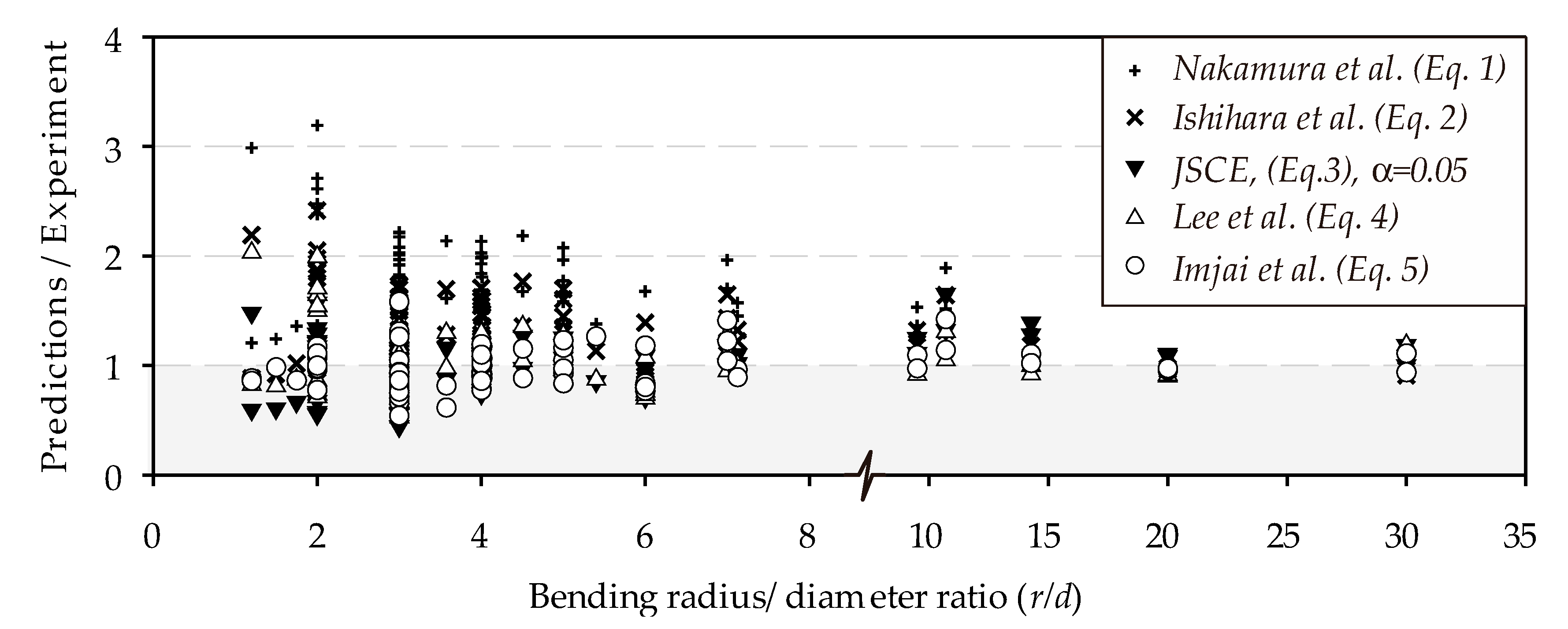
| Mean value (Prediction/Experiment) | 1.66 | 1.34 | 1.02 | 1.28 | 1.08 | 0.98 | 1.00 | |||||||||
| Standard deviation (Prediction/Experiment) | 0.46 | 0.33 | 0.27 | 0.32 | 0.28 | 0.18 | 0.25 | |||||||||
References
- Taerwe, L. FRP Activities in Europe: Survey of Research and Applications. In Proceedings of the Non-Metallic (FRP) Reinforcement for Concrete Structures, Third International Symposium, Sapporo, Japan, 14–16 October 1997; pp. 59–74. [Google Scholar]
- Imjai, T. Advanced composites for civil engineering applications. In Proceedings of the First International Conference on Composites in Infrastructure, Tucson, Arizona, 15–17 January 1996. [Google Scholar]
- Plecnik, J.; Ahmad, S.H. Transfer of Composite Technology to Design and Construction of Bridges; Final Rep. to USDOT; Contract No. DTRS 5683–C000043; Federal Highway Administration: Washington, WA, USA, 1988; p. 243. [Google Scholar]
- Benmokrane, B.; Chaallal, O.; Masmoudi, R. Flexural Response of Concrete Beams Reinforced with FRP Reinforcing Bars. ACI Struct. J. 1996, 93, 46–55. [Google Scholar]
- El-Salakawy, E.; Benmokrane, B. Serviceability of Concrete Bridge Deck Slabs Reinforced with Fiber-Reinforced Polymer Composite Bars. ACI Struct. J. 2004, 101, 727–736. [Google Scholar]
- Gravina, R.J.; Smith, S.T. Flexural behaviour of indeterminate concrete beams reinforced with FRP bars. J. Eng. Struct. 2008, 30, 2370–2380. [Google Scholar] [CrossRef]
- Teng, J.G.; Chen, J.F.; Smith, S.T.; Lam, L. Behaviour and strength of FRP-strengthened RC structures: A state-of-the-art review. Proc. Inst. Civ. Eng. Struct. Build. 2003, 156, 51–62. [Google Scholar] [CrossRef]
- Van Den Einde, L.; Zhao, L.; Seible, F. Use of FRP composites in civil structural applications|Lelli Van Den Einde-Academia.edu. Constr. Build. Mater. 2003, 17, 389–403. [Google Scholar] [CrossRef]
- Kim, Y.J. State of the practice of FRP composites in highway bridges. Eng. Struct. 2019, 179, 1–8. [Google Scholar] [CrossRef]
- Mara, V.; Haghani, R.; Harryson, P. Bridge decks of fibre reinforced polymer (FRP): A sustainable solution. Constr. Build. Mater. 2014, 50, 190–199. [Google Scholar] [CrossRef] [Green Version]
- Burgoyne, C.; Balafas, I. Why is FRP not a Financial Success? In Proceedings of the 8th International Conference FRP, University of Patras, Patras, Greece, 16–18 July 2007; pp. 1–10. [Google Scholar]
- Shapira, B.A.; Bank, L.C. Constructability and economics of FRP reinforcement cages for concrete beams. J. Compos. Constr. 1997, 1, 82–89. [Google Scholar] [CrossRef]
- Nishizaki, I.; Takeda, N.; Ishizuka, Y.; Shimomura, T. A case study of life cycle cost based on a real FRP bridge. In Proceedings of the 3rd International Conference on FRP Composites in Civil Engineering (CICE 2006), Miami, FL, USA, 13–15 December 2006; pp. 1–4. [Google Scholar]
- Lee, L.S.; Jain, R. The role of FRP composites in a sustainable world. Clean Technol. Environ. Policy 2009, 11, 247–249. [Google Scholar] [CrossRef]
- Berg, A.C.; Bank, L.C.; Oliva, M.G.; Russell, J.S. Construction and cost analysis of an FRP reinforced concrete bridge deck. Constr. Build. Mater. 2006, 20, 515–526. [Google Scholar] [CrossRef]
- CurvedNFR. Final Report of the CRAFT RTD Project Curved NFR Funded by the EU Commission Framework 5 GROWTH Programme; Sheffield, UK, 2015. [Google Scholar]
- Ibell, T.; Darby, A.S. Denton Research issues related to the appropriate use of FRP in concrete structures. Constr. Build. Mater. 2009, 23, 1521–1528. [Google Scholar] [CrossRef] [Green Version]
- Benmokrane, B.; Wang, P.; Ton-That, M.T.; Laoubi, K. Durability of GFRP composites reinforcing rods in concrete environment. In Proceedings of the 5th International Conference on Fibre-Reinforced Plastics for Reinforced Concrete Structures, Thomas Telford, London, UK; 2001; pp. 469–478. [Google Scholar]
- Li, R. Time-temperature superposition method for glass transition temperature of plastic materials. Mater. Sci. Eng. 2000, 278, 36–45. [Google Scholar] [CrossRef]
- Gopal, A.K.; Adali, S.; Verijenko, V.E. Optimal temperature profiles for minimum residual stress in the cure process of polymer composites. Compos. Struct. 2000, 48, 99–106. [Google Scholar] [CrossRef]
- Davies, L.W.; Day, R.J.; Bond, D.; Nesbitt, A.; Ellis, J.; Gardon, E. Effect of cure cycle heat transfer rates on the physical and mechanical properties of an epoxy matric composites. Compos. Sci. Technol. 2010, 67, 1892–1899. [Google Scholar] [CrossRef]
- Hollaway, L.C. Key issues in the use of fibre reinforced polymer (FRP) composites in the rehabilitation and retrofitting of concrete struc-ture. In Service Life Estimation and Extension of Civil Engineering Struc-Tures; Karbhari, V.M., Lee, L.S., Eds.; Woodhead: Cambridge, UK, 2011; pp. 3–74. [Google Scholar]
- Benmokrane, B.; Mohamed, K.; Cousin, P. Performance and Durability of In-Plant Partially Cured GFRP Bent Bars in Steam-Cured Precast Concrete Elements. J. Compos. Constr. 2020, 24, 1–14. [Google Scholar] [CrossRef]
- Abbasi, A.; Hogg, P.J. Fire testing of concrete beams with fibre reinforced plastic rebar. Compos. Part A Appl. Sci. Manuf. 2006, 37, 1142–1150. [Google Scholar] [CrossRef]
- Aruniit, A.; Kers, J.; Krumme, A.; Poltimäe, K.T. Preliminary study of the influence of post curing parameters to the par- ticle reinforced composite’s mechanical and physical properties. Mater. Sci. 2012, 18, 256–261. [Google Scholar]
- Kumar, D.S.; Shukla, M.J.; Mahato, K.K.; Rathore, D.K.; Prusty, R.K.; Ray, B.C. Effect of post-curing on thermal and mechanical be- havior of GFRP composites. IOP Conf. Ser. Mater. Sci. Eng. 2015, 75, 1–7. [Google Scholar] [CrossRef] [Green Version]
- Krishna, R.; Revathi, A.; Srihari, S.; Rao, R. Post-curing effects on hygrothermal behavior of RT-cured glass/epoxy composites. J. Reinf. Plast. Compos. 2010, 29, 325–330. [Google Scholar] [CrossRef]
- Wang, Y.C.; Wong, P.M.H.; Kodur, V. An experimental study of the mechanical properties of fibre reinforced polymer (FRP) and steel reinforcing bars at elevated temperatures. Compos. Struct. 2007, 80, 131–140. [Google Scholar] [CrossRef]
- Robert, M.; Wang, P.; Cousin, P.; Benmokrane, B. Temperature as an accelerating factor for long-term durability testing of FRPs: Should there be any limitations? J. Compos. Constr. 2010, 14, 361–367. [Google Scholar] [CrossRef]
- British Standard Institution. BS 8666:2005 Specification for Scheduling, Dimensioning, Bending, and Cutting of Steel Reinforcement for Concrete; BSI: London, UK, 2005. [Google Scholar]
- Imjai, T.; Guadagnini, M.; Pilakoutas, K.; Waldron, P. Curved Non-Ferrous Reinforcement for Concrete Structures. In Measuring, Monitoring and Modeling Concrete Properties; Springer: Dordrecht, The Netherlands, 2006; pp. 719–728. [Google Scholar]
- Imjai, T.; Guadagnini, M.; Pilakoutas, K. Curved FRP as concrete reinforcement. Proc. Inst. Civ. Eng. Eng. Comput. Mech. 2009, 162, 171–178. [Google Scholar] [CrossRef]
- Imjai, T.; Guadagnini, M.; Pilakoutas, K. Bend strength of FRP bars: Experimental investigation and bond modeling. J. Mater. Civ. Eng. 2017, 29, 1–11. [Google Scholar] [CrossRef]
- ACI 440.1R-15. Guide for the Design and Construction of Concrete Reinforced with FRP Bars; American Concrete Institute (ACI): Farmington Hills, MI, USA, 2015. [Google Scholar]
- CAN/CSA-S806-02. Design and Construction of Building Components with Fibre Reinforced Polymers; Canadian Standards Association: Toronto, ON, Canada, 2002. [Google Scholar]
- Fib Bulletin 40. FRP Reinforcement in Concrete Structures; Fib Technical Report, Task Group 9.3; Sprint-Digital-Druck: Lausanne, Switzerland, 2007; p. 151. Available online: https://www.iranfrp.ir/wp-content/uploads/2018/12/40-FRP-reinforcement-in-RC-structures_0-1.pdf (accessed on 23 July 2020).
- Guadagnini, M.; Imjai, T.; Pilakoutas, K. The Performance of Curved FRP Reinforcement for Concrete Structures. In Proceedings of the Non-Metallic (FRP) Reinforcement for Concrete Structures, the 8th International Symposium on Non-Metallic (FRP) Reinforcement for Co ncrete Structures (FRPRCS-8), Patras, Greece, 16–18 July 2007; pp. 462–463. [Google Scholar]
- Imjai, T. Design and Analysis of Curved Frp Composites as Shear Reinforcement for Concrete Structures. Ph.D. Thesis, The University of Sheffield, Sheffield, UK, 2007; p. 284. [Google Scholar]
- Hues Brothers Inc. Glass Fiber Reinforced Polymer (GFRP) Rebar—Aslan 100 Series. Available online: www.aslanfrp.com (accessed on 23 July 2020).
- Porter, M.L.; Harries, K. Future directions for research in FRP composites in concrete construction. J. Compos. Constr. 2007, 11, 252–257. [Google Scholar] [CrossRef]
- Elgabbas, F.; Ahmed, E.; Benmokrane, B. Basalt FRP reinforcing bars for concrete structures. In Proceedings of the 4th Asia-Pacific Conference on FRP in Structures, APFIS 2013, Melbourne, Australia, 11–13 December 2013; Volume 440, pp. 11–13. [Google Scholar]
- Wu, H.C.; Eamon, C.D. Strengthening of Concrete Structures Using Fiber Reinforced Polymers (FRP): Design, Construction and Practical Applications; Woodhead Publishing: Cambridge, UK, 2017; ISBN 9780081006368. [Google Scholar]
- Maruyama, T.; Honma, M.; Okamura, H. Experimental Study on Tensile Strength of Bent Portion of FRP Rods. In Proceedings of the Non-Metallic (FRP) Reinforcement for Concrete Structures, 2nd RILEM Symposium (FRPRCS-2), London, UK, 1 September 1995; pp. 163–176. [Google Scholar]
- Vint, L.; Sheikh, S. Investigation of bond properties of alternate anchorage schemes for glass fiber-reinforced polymer bars. ACI Struct. J. 2015, 112, 59–68. [Google Scholar]
- Japan Society of Civil Engineers. Recommendation for Design and Construction of Concrete Structures Using Continuous Fiber Reinforcing Materials; Japan Society of Civil Engineers: Tokyo, Japan, 1997. [Google Scholar]
- Ehsani, M.R.; Saadatmanesh, H.; Tao, S. Bond of Hooked Glass Fiber Reinforced Plastic (GFRP) Reinforcing Bars to Concrete. ACI Mater. J. 1995, 122, 247–257. [Google Scholar]
- Nagasaka, T.; Fukuyama, H.; Tanigaki, M.S. Shear Performance of Concrete Beams Reinforced with FRP Stirrups. In Proceedings of the International Symposium on Fiber-Reinforced-Plastic Reinforcement for Concrete Structures (FRPRCS-1), Vancouver, BC, Canada, 28–31 March 1993; pp. 789–812. [Google Scholar]
- Lee, C.; Ko, M.; Lee, Y. Bend strength of complete closed-type carbon fiber-reinforced polymer stirrups with rectangular section. J. Compos. Constr. 2014, 18, 1–11. [Google Scholar] [CrossRef]
- Shehata, E.; Morphy, R.; Rizkalla, S. Fibre reinforced polymer shear reinforcement for concrete members: Behaviour and design guidelines. Can. J. Civ. Eng. 2000, 27, 859–872. [Google Scholar] [CrossRef]
- Ishihara, K.; Obara, T.; Sato, Y.; Kakuta, Y. Evaluation of ultimate strength of FRP rods at bent-up portion. In Proceedings of the 3rd International Symposium on Non-Metallic (FRP) Reinforcement for Concrete Structures, Sapporo, Japan, 14–16 October 1997; pp. 27–34. [Google Scholar]
- Ahmed, E.A.; El-Sayed, A.K.; El-Salakawy, E.; Benmokrane, B. Bend strength of FRP stirrups: Comparison and evaluation of testing methods. J. Compos. Constr. 2010, 14, 3–10. [Google Scholar] [CrossRef]
- Nakamura, H.; Higai, I. Evaluation of Shear Strength on Concrete Beams Reinforced with FRP. Concr. Libr. JSCE 1995, 26, 111–123. [Google Scholar]
- Morphy, R.; Sheata, E.; Rizkalla, S. Bent Effect on Strength of CFRP StirrupsBent Effect on Strength of CFRP Stirrups. In Proceedings of the 3rd International Symposium on Non-Metallic (FRP) Reinforcement for Concrete Structures, Sapporo, Japan, 14–16 October 1997; pp. 19–26. [Google Scholar]
- Ahmed, E.A. Shear Behaviour of Concrete Beams Reinforced with Fibre-Reinforced Polymer (FRP) Stirrups. Ph.D. Thesis, University of Sherbrooke, Quebec, QC, Canada, 2009; p. 316. [Google Scholar]
- Spadea, S.; Orr, J.; Ivanova, K. Bend-strength of novel filament wound shear reinforcement. Compos. Struct. 2017, 176, 244–253. [Google Scholar] [CrossRef] [Green Version]
- Ascione, L.; Razaqpur, A.G.; Spadea, S. Effectiveness of FRP stirrups in concrete beams subject to shear. In Proceedings of the 7th International Conference on FRP Composites in Civil Engineering (CICE 2014), Vancouver, Cannada, 20–22 August 2014; pp. 368–395. [Google Scholar]
- Razaqpur, A.G.; Spadea, S. Shear Strength of FRP Reinforced Concrete Members with Stirrups. J. Compos. Constr. ASCE 2015, 19, 04014025. [Google Scholar] [CrossRef]
- ISIS M03-01. Reinforcing Concrete Structures with Fibre Reinforced Polymers; Design Manual No. 3, Canadian Network of Centres of Excellence on Intelligent Sensing for Innovative Structures; ISIS Canada: Winnipeg, MB, Canada, 2001. [Google Scholar]
- Imjai, T.; Guadagnini, M.; Pilakoutas, K.; Garcia, R.; Sukontasukkul, P.; Limkatanyu, S. A practical macro-mechanical model for the bend capacity of fibre-reinforced polymer bars. In Proceedings of the Institution of Civil Engineers—Structures and Buildings; Thomas Telford Services Ltd.: London, UK, 2020; pp. 1–12. Available online: https://www.icevirtuallibrary.com/doi/abs/10.1680/jstbu.19.00135 (accessed on 23 July 2020).
- Ozawa, K.; Sekijima, K.; Okamura, H. Flexural Fatigue Bahaviour of Concrete Beams with FRP Reinforcemen. Trans. Jpn. Concr. Inst. 1987, 9, 289–296. [Google Scholar]
- Miyata, S.; Tottori, S.; Terada, T.; Sekijima, K. Experimental study on tensile strength of FRP bent bar. Trans. Jpn. Concr. Inst. 1989, 11, 185–191. [Google Scholar]
- ACI Committee 440 Guide for the Design and Construction of Structural Concrete Reinforced with Firber-Reinforced Polymer (FRP) Bars (ACI 440.1R-15); American Concrete Institute: Farmington Hills, MI, USA, 2015; p. 88. Available online: file:///C:/Users/TI/Downloads/GuideforthedesignandconstructionofconcretereinforcedwithFiberRienforcedPolymersFRPbarsACI440%20(1).pdf (accessed on 23 July 2020).
- El Chabib, H.; Nehdi, M. Shear capacity of FRP stirrups in FRP-reinforced concrete beams based on genetic algorithms approach. In Proceedings of the Structures Congress 2008: Crossing Borders, Vancouver, BC, Canada, 24–26 April 2008; pp. 1–9. [Google Scholar]
- El-Sayed, A.K.; El-Salakawy, E.; Benmokrane, B. Mechanical and structural characterization of new carbon FRP stirrups for concrete members. J. Compos. Constr. 2007, 11, 352–362. [Google Scholar] [CrossRef]
- Ueda, T.; Sato, Y.; Kakuta, Y.; Imamura, A.; Kanematsu, H. Failure Criteria for FRP rods Subjected to a Combination of Tensile and Shear Forces. In Proceedings of the Non-Metallic (FRP) Reinforcement for Concrete Structures, 2nd RILEM symposium (FRPRCS-2), Ghent, Belgium, 23–25 August 1995; pp. 26–33. Available online: https://www.tib.eu/en/search/id/TIBKAT%3A189417463/Non-metallic-FRP-reinforcement-for-concrete-structures/ (accessed on 23 July 2020).
- Imjai, T.; Guadagnini, M.; Garcia, R.; Pilakoutas, K. A practical method for determining shear crack induced deformation in FRP RC beams. Eng. Struct. 2016, 126, 353–364. [Google Scholar] [CrossRef]
- Liu, J.; Zhao, Y.; Yang, Y.; Chen, Y.F. Bending Capacity and Elastic Stiffness for a Novel Configuration of Cold-Formed U-Shaped Steel-and-Concrete Composite Beams. J. Struct. Eng. 2019, 145, 1–12. [Google Scholar] [CrossRef]
- Spadea, S.; Orr, J.; Nanni, A.; Yang, Y. Wound FRP Shear Reinforcement for Concrete Structures. J. Compos. Constr. 2017, 21, 1–13. [Google Scholar] [CrossRef] [Green Version]
- Mohamed, H.M.; Ali, A.H.; Benmokrane, B. Behavior of Circular Concrete Members Reinforced with Carbon-FRP Bars and Spirals under Shear. J. Compos. Constr. 2017, 21, 1–12. [Google Scholar] [CrossRef]
- Mohamed, H.M.; Chaallal, O.; Benmokrane, B. Torsional moment capacity and failure mode mechanisms of concrete beams reinforced with carbon FRP bars and stirrups. J. Compos. Constr. 2015, 19, 1–10. [Google Scholar] [CrossRef]
- El-Sayed, A.K.; Soudki, K. Evaluation of shear design equations of concrete beams with FRP reinforcement. J. Compos. Constr. 2011, 15, 9–20. [Google Scholar] [CrossRef]
- Ahmed, E.A.; El-Salakawy, E.F.; Benmokrane, B. Shear performance of RC Bridge girders reinforced with carbon FRP stirrups. J. Bridg. Eng. 2010, 15, 44–54. [Google Scholar] [CrossRef]
- Currier, I.; Fogstad, C.; Walrath, D.; Dolan, C. Bond Development of Thermoplastic FRP Shear Reinforcement Stirrups. In Proceedings of the Third Materials Engineering Conference, San Diego, CA, USA, 13–16 November 1994; pp. 592–597. [Google Scholar]
- ACI 440.3R-04. 3R-04. Guide Test Methods for Fiber-Reinforced Polymer (FRP) Composites for Reinforcing or Strengthening Concrete and Masonry Structures; American Concrete Institute (ACI): Farmington Hills, MI, USA, 2012. [Google Scholar]
- ACI 318-14. Building Code Requirements for Structural Concrete; American Concrete Institute: Farmington Hills, MI, USA, 2014. [Google Scholar]
- Garcia, R.; Pilakoutas, K.; Hajirasouliha, I.; Guadagnini, M.; Kyriakides, N.; Ciupala, M.A. Seismic retrofitting of RC buildings using CFRP and post-tensioned metal straps: Shake table tests. Bull. Earthq. Eng. 2017, 15, 3321–3347. [Google Scholar] [CrossRef] [Green Version]
- Garcia, R.; Jemaa, Y.; Helal, Y.; Guadagnini, M.; Pilakoutas, K. Seismic strengthening of severely damaged beam-column RC joints using CFRP. J. Compos. Constr. 2014, 18, 1–10. [Google Scholar] [CrossRef] [Green Version]
- Garcia, R.; Hajirasouliha, I.; Pilakoutas, K. Seismic behaviour of deficient RC frames strengthened with CFRP composites. Eng. Struct. 2010, 32, 3075–3085. [Google Scholar] [CrossRef] [Green Version]
- Yang, X.; Wei, J.; Nanni, A.; Dharani, L.R. Shape Effect on the Performance of Carbon Fiber Reinforced Polymer Wraps. J. Compos. Constr. ASCE 2004, 8, 444–451. [Google Scholar] [CrossRef] [Green Version]
- Robert, M.; Benmokrane, B. Effect of aging on bond of GFRP bars embedded in concrete. Cem. Concr. Compos. 2010, 32, 461–467. [Google Scholar] [CrossRef]
- Williams, B.; Kodur., V.; Green, M.; Bisby., L. Fire endurance of fiber-reinforced polymer strengthened concrete T-beams. J. ACI Struct. 2008, 105, 60–67. [Google Scholar]
- Alsayed, S.H. Flexural behaviour of concrete beams reinforced with GFRP bars. Cem. Concr. Compos. 1998, 20, 1–11. [Google Scholar] [CrossRef]
- Katz, A.; Berman, N. Modeling the effect of high temperature on the bond of FRP reinforcing bars to concrete. Cem. Concr. Compos. 2000, 22, 433–443. [Google Scholar] [CrossRef]
- Saafi, M. Effect of fire on FRP reinforced concrete members. Compos. Struct 2002, 58, 11–20. [Google Scholar] [CrossRef]
- Bisby, L.A. Fire Behavior of Fiber-Reinforced Polymer Reinforced or Confined Concrete. Ph.D. Thesis, Queen’s University, Kingston, ON, Canada, 2003. [Google Scholar]
- Adimi, R.; Rahman, H.; Benmokrane, B.; Kobayashi, K. Effect of temperature and loading frequency on the fatigue life of a CFRP bar in concrete. In Proceedings of the second international conference on composites in infrastructure (ICCI-98), Tucson, Arizona, 5–7 January 1998; pp. 203–210. [Google Scholar]
- British Standard Institution. Fire Tests on Building Materials and Structures. Part 20. Method of Determination of Fire Resistance of Load Bearing Elements of Constructions; BS 476; British Standard Institution: London, UK, 1987. [Google Scholar]
- Hawileh, R.A.; Naser, M.Z. Thermal-stress analysis of RC beams reinforced with GFRP bars. Compos. Part B Eng. 2012, 43, 2135–2142. [Google Scholar] [CrossRef]
- Hawileh, R.; Naser, M.; Rasheed, H. Thermal-stress finite element analysis of CFRP strengthened concrete beam exposed to top surface fire. Mech. Adv. Mater. Struct. 2011, 18, 172–180. [Google Scholar] [CrossRef]
- Hawileh, R.; Naser, M.; Zaidan, W.; Rasheed, H. Modeling of insulated CFRPstrengthened reinforced concrete T-beam exposed to fire. Eng. Struct. 2009, 31, 3072–3079. [Google Scholar] [CrossRef]
- ISO 834-2. Ire-resistance Tests — Elements of Building Construction — Part 2: Requirements and Recommendations for Measuring Furnace Exposure on Test Samples; The International Standards Organisation: Geneva, Switzerland, 2019; p. 14. Available online: https://www.iso.org/standard/75137.html (accessed on 23 July 2020).
- Mochizuki, S.; Matsuzaki, Y.; Sugita, M. Evaluation Items and Methods of FRP Reinforcement as Structural Element. Trans. Jpn. Concr. Inst. 1989, 11, 117–131. [Google Scholar]
- ISIS. Specifications for Product Certification on Fibre Reinforced Polymers (FRPs) as Internal Reinforcement in Concrete Structures; University of Manitoba: Winnipeg, MB, Canada, 2006; Product ce. [Google Scholar]
- ACI 440.6M-08. Specification for Carbon and Glass Fiber-Reinforced Polymer Bar Materials for Concrete Reinforcement; American Concrete Institute (ACI): Farmington Hills, MI, USA, 2008. [Google Scholar]
- Pilakoutas, K.; Guadagnini, M.; Neocleous, K.; Matthys, S. Design guidelines for FRP reinforced concrete structures. Proc. Inst. Civ. Eng. Struct. Build. 2011, 164, 255–263. [Google Scholar] [CrossRef] [Green Version]
- ISIS-M03-07. Reinforcing Concrete Structures with Fiber Reinforced Polymers; University of Winnipeg: Winnipeg, MB, Canada, 2007. [Google Scholar]
- Bright, R.J.; Sumathi, M. Failure Analysis of FRP Composite Laminates Using Progressive Failure Criteria. Int. J. Sci. Eng. Res. 2017, 8, 12. [Google Scholar]
- Talreja, R. Assessment of the fundamentals of failure theories for composite materials. Compos. Sci. Technol. 2014, 105, 190–201. [Google Scholar] [CrossRef]
- Frketic, J.; Dickens, T.; Ramakrishnan, S. Automated manufacturing and processing of fiber-reinforced polymer (FRP) composites: An additive review of contemporary and modern techniques for advanced materials manufacturing. Addit. Manuf. 2017, 14, 69–86. [Google Scholar] [CrossRef] [Green Version]
- Lee, C.; Lee, S.; Shin, S. Shear Capacity of RC Beams with Carbon Fiber-464 Reinforced Polymer Stirrups with Rectangular Section. J. Compos. Constr. 2016, 20, 1–11. [Google Scholar] [CrossRef]
- Chakrabortty, A.; Khennane, A.; Kayali, O.; Morozov, E. Performance of outside filament-wound hybrid FRP-concrete beams. Compos. Part B Eng. 2011, 42, 907–915. [Google Scholar] [CrossRef]
- Ali, A.; Mohamed, H.; Benmokrane, B. Shear behavior of circular concrete members reinforced with GFRP bars and spirals at shear span-to-depth ratios between 1.5 and 3.0. J. Compos. Constr. 2016, 20, 1–16. [Google Scholar] [CrossRef]


| References | Remarks | |
|---|---|---|
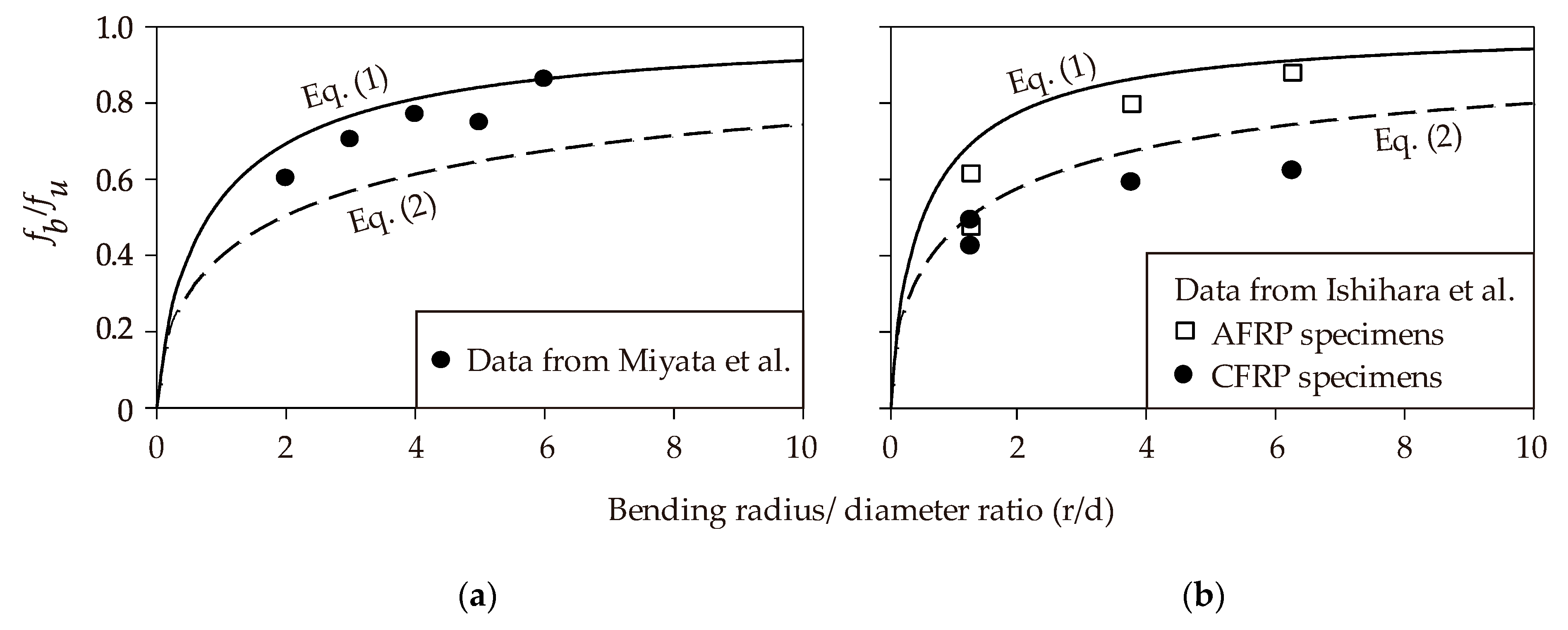
| Nakamura and Higai [52] | Empirical model derived using test data from Miyata et al. [61]. | |
| (1) | ||
| Ishihara et al. [50] | Derived using test data from Ishihara et al. [50] and further compared to the numerical results obtained from a 2D FE analysis. | |
| (2a) | ||
| where | (2b) | |
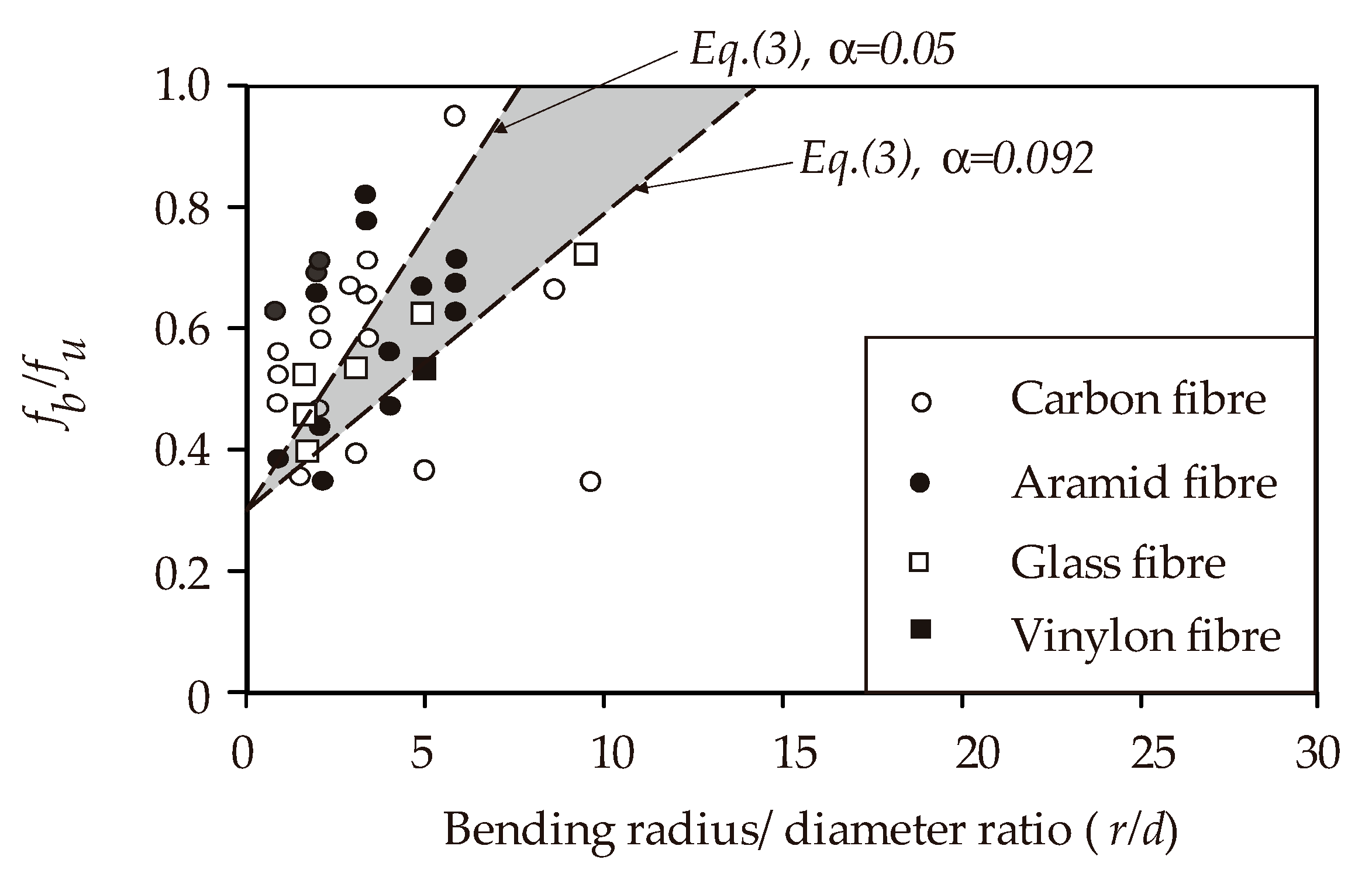
| JSCE [45] | Empirical model based on test results obtained by Japanese researchers. Unfortunately, information on these tests is not available for all of the specimens and only selected test data from JSCE extracted from Ishihara et al. [50] are presented in the appendix. | |
| (3) | ||
| Lee et al. [48] | Equation (4) is a modification of Equation (3), but the former can be applied to non-circular sections. The model uses the diameter of the equivalent circular section by converting non-circular bars to equivalent circular bars, . α values were obtained from linear regression analysis from 14 tests. | |
| (4) | ||
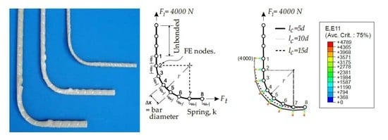
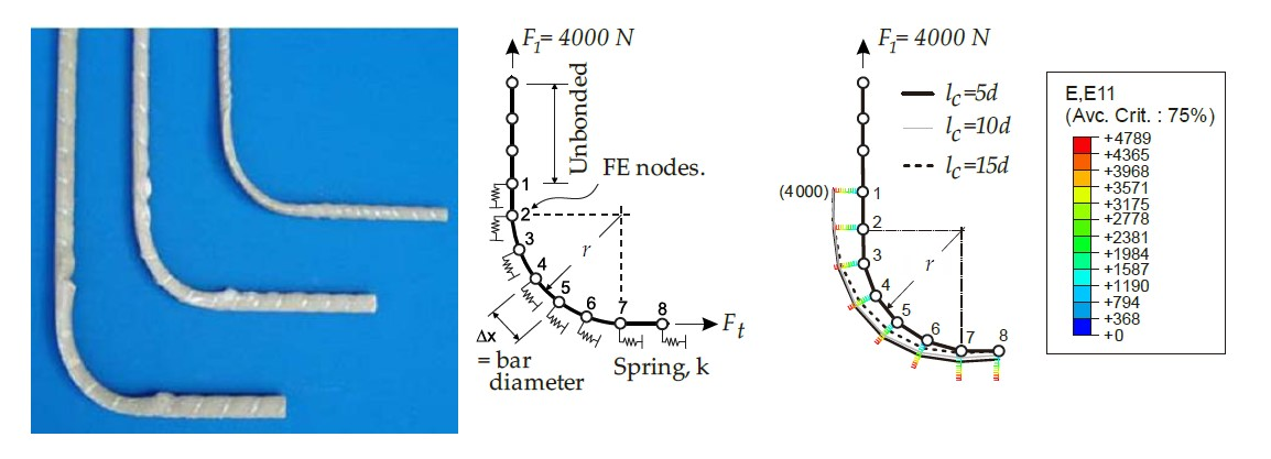
| Imjai et al. [59] | The model adopts the Tsai–Hill failure criterion for a unidirectional orthotropic laminar composite at a macroscopic level and considers force equilibrium at the bent zone. The model is calibrated using test results from 26 tests [33] and subsequently verified against 54 test results available in the literature. | |
| (5a) | ||
| where | (5b) |
© 2020 by the authors. Licensee MDPI, Basel, Switzerland. This article is an open access article distributed under the terms and conditions of the Creative Commons Attribution (CC BY) license (http://creativecommons.org/licenses/by/4.0/).
Share and Cite
Imjai, T.; Garcia, R.; Guadagnini, M.; Pilakoutas, K. Strength Degradation in Curved Fiber-reinforced Polymer (FRP) Bars Used as Concrete Reinforcement. Polymers 2020, 12, 1653. https://doi.org/10.3390/polym12081653
Imjai T, Garcia R, Guadagnini M, Pilakoutas K. Strength Degradation in Curved Fiber-reinforced Polymer (FRP) Bars Used as Concrete Reinforcement. Polymers. 2020; 12(8):1653. https://doi.org/10.3390/polym12081653
Chicago/Turabian StyleImjai, Thanongsak, Reyes Garcia, Maurizio Guadagnini, and Kypros Pilakoutas. 2020. "Strength Degradation in Curved Fiber-reinforced Polymer (FRP) Bars Used as Concrete Reinforcement" Polymers 12, no. 8: 1653. https://doi.org/10.3390/polym12081653