Fiber Reinforced Polymer Laminates for Strengthening of RC Slabs against Punching Shear: A Review


Abstract
:1. Introduction
2. Punching Shear Strength in Selected Codes and Standards
3. Experimental Specimens, FRP Strengthening Patterns, and Methods
4. Results of Experimental Studies and Major Findings
5. Conclusions
6. Need for Future Research
Author Contributions
Funding
Conflicts of Interest
References
- Zaghlal, M.Y.A. Punch Resistance of Slab Column Connection under Lateral Loads. Master’s Thesis, Zagazig University, Zagazig, Egypt, 2009. [Google Scholar]
- Alexander, S.; Simmonds, S. Shear-moment transfer in slab–column connections. In Structural Engineering Report; University of Alberta: Edmonton, AB, Canada, 1989; p. 95. [Google Scholar]
- Guandalini, S.; Burdet, O.L.; Muttoni, A. Punching tests of slabs with low reinforcement ratios. ACI Struct. J. 2009, 106, 87–95. [Google Scholar]
- Moe, J. Shearing Strength of Reinforced Concrete Slabs and Footings under Concentrated Loads; Portland Cement Association: Skokie, IL, USA, 1961; Volume D47, p. 135. [Google Scholar]
- Gomes, R.B.; Regan, P.E. Punching resistance of RC flat slabs with shear reinforcement. ACI Struct. J. 1999, 125, 684–692. [Google Scholar] [CrossRef]
- Ebead, U.; Marzouk, H. Strengthening of two-way slabs subjected to moment and cyclic loading. ACI Struct. J. 2002, 99, 435–444. [Google Scholar]
- Silva, M.A.L.; Madushanka, W.I.; Ariyasena, P.S.I.; Gamage, J.C.P.H. Punching Shear Capacity Enhancement of Flat Slabs Using End Anchored Externally Bonded CFRP Strips; Society of Structural Engineers: Colombo, Sri Lanka, 2018; Volume 28. [Google Scholar]
- Malalanayake, M.L.V.P.; Gamage, J.C.P.H.; Silva, M.A.L. Experimental investigation on enhancing punching shear capacity of flat slabs using CFRP. In Proceedings of the 8th International Conference on Structural Engineering and Construction Management (ICSECM2017), Kandy, Sri Lanka, 7–9 December 2017. [Google Scholar]
- Rasha, T.S.M.; Amr, B.; Hany, A. Effect of flexural and shear reinforcement on the punching behavior of reinforced concrete flat slabs. Alex. Eng. J. 2017, 56, 591–599. [Google Scholar]
- Dilger, W.; Birkle, G.; Mitchell, D. Effect of flexural reinforcement on punching shear resistance. Spec. Publ. 2005, 232, 57–74. [Google Scholar]
- Caldentey, A.P.; Lavaselli, P.P.; Peiretti, H.C.; Fernández, F.A. Influence of stirrup detailing on punching shear strength of flat slabs. Eng. Struct. 2013, 49, 855–865. [Google Scholar] [CrossRef]
- McHarg, P.J.; Cook, W.D.; Mitchell, D.; Yoon, Y.S. Benefits of concentrated slab reinforcement and steel fibres on performance of slab–column connections. ACI Struct. J. 2000, 97, 225–234. [Google Scholar]
- Elstner, R.C.; Hognestad, E. Shearing strength of reinforced concrete slabs. Int. Assoc. Bridges Struct. Eng. 1956, 53, 29–58. [Google Scholar]
- Inácio, M.; Ramos, A.; Lúcio, V.; Faria, D. Punching of High-Strength Concrete Flat Slabs-Experimental Investigation. In Proceedings of the Fib Symposium Tel Aviv 2013, Tel Aviv, Israel, 22–24 April 2013; Volume 293, p. 500. [Google Scholar]
- Alexander, S.D.; Simmonds, S.H. Tests of column-flat plate connections. ACI Struct. J. 1992, 89, 495–502. [Google Scholar]
- Hawkins, N.M.; Fallsen, H.B.; Hinojosa, R.C. Influence of Column Rectangularity on the Behavior of Flat Plate Structures. Spec. Publ. 1971, 30, 127–146. [Google Scholar]
- ACI Committee 318. Building Code Requirements for Structural Concrete and Commentary: ACI 318-14; American Concrete Institute: Detroit, MI, USA, 2011. [Google Scholar]
- European Committee for Standardization. EN 1992-1-1Eurocode 2: Design of Concrete Structures—Part 1-1: General Rules and Rules for Buildings; The European Union per Regulation 305/2011; European Committee for Standardization: Brussels, Belgium, 2004. [Google Scholar]
- ACI Committee 440. Guide for the Design and Construction of Structural Concrete Reinforced with Fiber-Reinforced Polymer Bars: ACI 440.1R-15; American Concrete Institute: Detroit, MI, USA, 2015. [Google Scholar]
- Weng, Y.; Qian, K.; Fu, F.; Fang, Q. Numerical investigation on load redistribution capacity of flat slab substructures to resist progressive collapse. J. Build. Eng. 2020, 29, 101109. [Google Scholar] [CrossRef]
- Mohamed, O.; Khattab, R.A.; Mishra, A.; Isam, F. Recommendations for reducing progressive collapse potential in flat slab structural systems. IOP Conf. Ser. Mater. Sci. Eng. 2019, 471, 052069. [Google Scholar] [CrossRef]
- Canadian Standards Association. Design and Construction of Building Structures with Fiber-Reinforced Polymer 2012; CAN/CSA S806-12; Canadian Standards Association: Toronto, ON, Canada, 2012. [Google Scholar]
- British Standards Institution. Structural Use of Concrete—Code of Practice for Design and Construction; British Standards Institution: London, UK, 1997. [Google Scholar]
- Japan Society of Civil Engineering. Recommendation for Design and Construction of Concrete Structures Using Continuous Fiber Reinforcing Materials; Concrete Engineering Series 23; Japan Society of Civil Engineering: Tokyo, Japan, 1997. [Google Scholar]
- Binici, B.; Bayrak, O. Punching shear strengthening of reinforced concrete flat plates using carbon fiber reinforced polymers. J. Struct. Eng. ASCE 2003, 229, 2273–2282. [Google Scholar] [CrossRef]
- Sissakis, K.; Sheikh, S.A. Strengthening concrete slabs for punching shear with carbon fiber-reinforced polymer laminates. ACI Struct. J. 2007, 104, 49–59. [Google Scholar]
- Harajli, M.H.; Soudki, K.A. Shear strengthening of interior slab–column connections using carbon fiber-reinforced polymer sheets. J. Compos. Constr. 2003, 7, 145–153. [Google Scholar] [CrossRef]
- El-Salakawy, E.; Soudki, K.A.; Polak, M.A. Punching shear behavior of flat slabs strengthened with fiber reinforced polymer laminates. J. Compos. Constr. 2004, 8, 384–392. [Google Scholar] [CrossRef]
- Chen, C.C.; Li, C.Y. Punching shear strength of reinforced concrete slabs strengthened with glass fiber-reinforced polymer laminates. ACI Struct. J. 2005, 202, 535–542. [Google Scholar]
- Liberati, E.A.P.; Marques, M.G.; Leonel, E.D.; Almeida, L.C.; Trautwein, L.M. Failure analysis of punching in reinforced concrete flat slabs with openings adjacent to the column. Eng. Struct. 2019, 182, 331–343. [Google Scholar] [CrossRef]
- Sharaf, M.H.; Soudki, K.A.; Dusen, M.V. CFRP strengthening for punching shear of interior slab–column connections. J. Compos. Constr. 2006, 10, 410–418. [Google Scholar] [CrossRef]
- Esfahani, M.R. Effect of cyclic loading on punching shear strength of slabs strengthened with carbon fiber polymer sheets. Int. J. Civ. Eng. 2008, 6, 208–215. [Google Scholar]
- Farghaly, A.S.; Ueda, T. Punching strength of two-way slabs strengthened externally with FRP sheets. JCI Proc. Jpn. Concr. Inst. 2009, 31, 493–498. [Google Scholar]
- Erdogan, H. Improvement of Punching Strength of Flat Plates by Using Carbon Fiber Reinforced Polymer (CFRP) Dowels. Ph.D. Thesis, Middle East Technical University, Ankara, Turkey, 2010. [Google Scholar]
- Urban, T.; Tarka, J. Strengthening of slab–column connections with CFRP strips. Arch. Civ. Eng. 2010, 56, 193–212. [Google Scholar] [CrossRef] [Green Version]
- Halabi, Z.; Ghrib, F.; El-Ragaby, A.M.; Sennah, K. Behavior of RC slab–column connections strengthened with external cfrp sheets and subjected to eccentric loading. J. Compos. Constr. 2013, 17, 488–496. [Google Scholar] [CrossRef]
- Abbas, H.; Abadel, A.A.; Almusallam, T.; Al Salloum, Y. Effect of CFRP and TRM strengthening of RC slabs on punching shear strength. Lat. Am. J. Solids Struct. 2015, 12, 1616–1640. [Google Scholar] [CrossRef] [Green Version]
- Radik, M.J.; Erdogmus, E.; Schafer, T. Strengthening two-way reinforced concrete floor slabs using polypropylene fiber reinforcement. J. Mater. Civ. Eng. ASCE 2011, 23, 562–571. [Google Scholar] [CrossRef]
- Soudki, K.; El-Sayed, A.K.; Vanzwol, T. Strengthening of concrete slab–column connections using CFRP strips. J. King Saud Univ. Eng. Sci. 2012, 24, 25–33. [Google Scholar] [CrossRef] [Green Version]
- Erdogan, H.; Zohrevand, P.; Mirmiran, A. Effectiveness of externally applied CFRP stirrups for rehabilitation of slab–column connections. J. Compos. Constr. ASCE 2013, 17, 04013008. [Google Scholar] [CrossRef]
- Hussein, A.H.; El-Salakawy, E.F. Punching shear behavior of glass fiber-reinforced polymer-reinforced concrete slab–column interior connections. ACI Struct. J. 2018, 115, 1075–1088. [Google Scholar] [CrossRef]
- Ferreira, M.D.; Oliveira, M.H.; Sales, G.; Melo, S.A. Tests on the punching resistance of flat slabs with unbalanced moments. Eng. Struct. 2019, 196, 109311. [Google Scholar] [CrossRef]
- Silva, M.A.L.; Gamagea, J.C.P.H.; Fawzia, S. Performance of slab–column connections of flat slabs strengthened with carbon fiber reinforced polymers. Case Stud. Constr. Mater. 2019, 11, e00275. [Google Scholar] [CrossRef]
- Durucan, C.; Anil, O. Effect of opening size and location on punching shear behavior of interior slab–column connections strengthened with CFRP strips. Eng. Struct. 2015, 105, 22–36. [Google Scholar] [CrossRef]
- Mohamed, O.A.; Khattab, R.; Okasha, R. Numerical analysis of RC slab with opening strengthened with CFRP laminates. IOP Conf. Ser. Mater. Sci. Eng. 2019, 603, 042038. [Google Scholar] [CrossRef] [Green Version]
- Lapi, M.; Ramos, A.P.; Orlando, M. Flat slab strengthening techniques against punching-shear. Eng. Struct. 2019, 180, 160–180. [Google Scholar] [CrossRef]
- Al-Gasham, T.S.; Mhalhal, J.M.; Jabir, H.A. Improving punching behavior of interior voided slab–column connections using steel sheets. Eng. Struct. 2019, 199, 109614. [Google Scholar] [CrossRef]
- Saleh, H.; Kalfat, R.; Abdouka, K.; Al-Mahaidi, R. Punching shear strengthening of RC slabs using L-CFRP laminates. Eng. Struct. 2019, 194, 274–289. [Google Scholar] [CrossRef]
- Goh, C.Y.M.; Hrynyk, T.D. Numerical investigation of the punching resistance of reinforced concrete flat plates. J. Struct. Eng. ASCE 2018, 144, 04018166. [Google Scholar] [CrossRef]


| Criteria | ACI 318-14 | Eurocode 2 (EC2) |
|---|---|---|
| Two-way shear strength model | The least of, (MPa) (a) (MPa) (b) (MPa) (c) is the critical perimeter for punching shear (mm). is the concrete compressive strength (MPA). Equation (a) represents the maximum punching shear capacity achievable without shear reinforcement. | is the flexural reinforcement ratio, is the concrete compressive strength |
| Location of critical perimeter for punching shear | d/2 (d = effective depth, mm) | 2d (d = effective depth, mm) |
| Effect of flexural reinforcement on punching shear capacity | Minimum flexural steel must be provided near tension face of the slab in two-perpendicular directions (, for grade 420 MPa reinforcement) (Section 8.6 [19] and commentary). Integrity reinforcement in column strip is required (8.7.4.2) to provide residual punching shear strength following punching shear failure. A minimum of two bottom bars shall pass in two directions through the region bounded by column vertical reinforcement and be anchored at exterior support. | Incorporated in punching shear strength formula. Clearly EC2 recognizes significant increase in punching shear strength in heavily reinforced slabs. |
| Effect of slab thickness on punching shear strength | It is incorporated in equation “c”, indicated punching shear capacity increases with increase in the ratio of effective depth to critical perimeter Implicitly addressed in the commentary by indicating that the minimum tension steel development length beyond column face on each side for slabs under predominantly uniform gravity load with clear span to depth ratio (ln/h) at less than 15. For thicker slabs with (ln/h), provide continuous tension steel to intercept punching shear cracks. | However, size effect parameter, limited by upper value of 2.0 is. |
| Effect of supporting member dimensions on punching shear strength | Incorporated in the parameter , which represents the ratio of the long support side to the short side. Upper limit on punching shear strength is (MPa) around corners of columns and decreases to or less along long sides of the support between the two end sections | Not explicitly indicated in the capacity expression. |
| Code | Critical Section Location | Equations |
|---|---|---|
| ACI318-14 [17] | 0.5 d | The least of, (MPa) (a) (MPa) (b) (c) |
| CSA-S806-12 [22] | 0.5 d | Vc = min βc: is the ratio of the long side to short side of the column λ = 1.00 b0.5: is the length of the critical shear perimeter |
| BS-8110 [23] | 1.5 d | Vcu = b1.5: is the length of the critical shear perimeter |
| Euro Code 2 [18] | 2 d | VRd = min σwd = γs = γCFRP = |
| JSCE [24] | 0.5 d | Vpvd = fpcd = min βd = min βρ = min βr = bw: is the length of the critical shear perimeter γb = 1.30 |
| Reference/Size of Slab (mm) | Slab ID/Number of Samples | FRP Type | fc′ MPa | Ultimate Load (kN) | Conclusions |
|---|---|---|---|---|---|
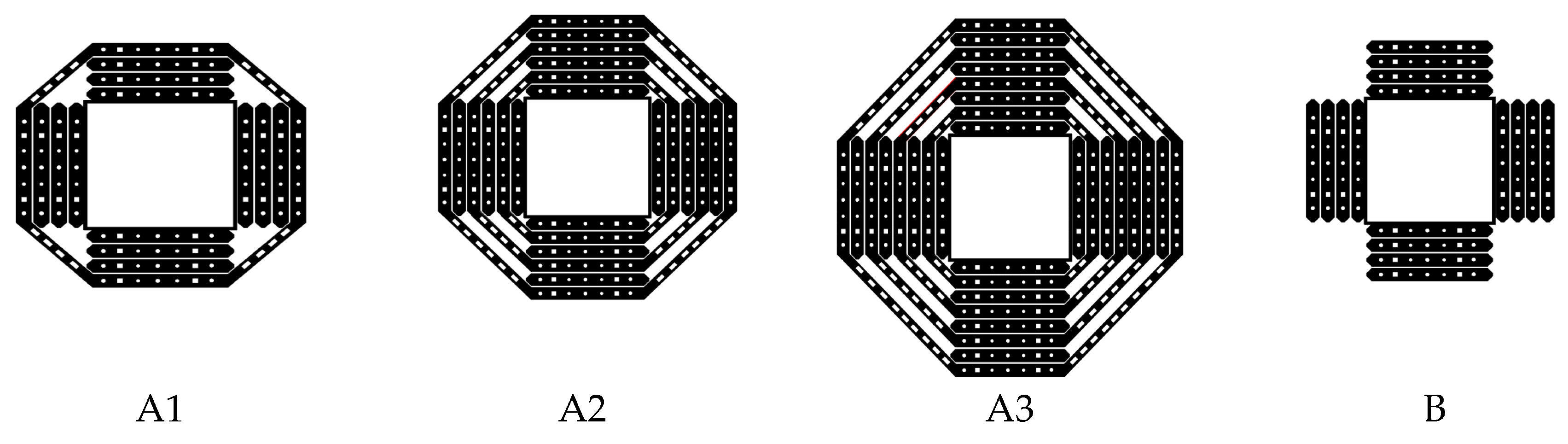
| Binici and Bayrak [25] Specimen size (mm) 2133 × 2133 × 152 | Control 1 | No CFRP | 28.3 | 494 | 1. Use of vertical CFRP strips inside pre-drilled holes, simulating stirrups is effective in enhancing punching shear capacity. Specimens with diagonal CFRP strips in addition to the vertical strips offered the highest enhancement in punching shear strength inside the shear reinforced zone. 2. The ultimate load carrying capacity and ductility of specimen A8, which was reinforced with vertical CFRP strips along with diagonal ones, were 1.51 and 2.0 times those of the control specimen Control (Control 1). 3. The enhancement in load-carrying capacity in specimen with highest CFRP strips and diagonal strips (A8) caused the yield length of steel reinforcement measured from the face of the loading plate to increase significantly compared to the control unstrengthen specimen (Control 1). |
| Control 2 | 510 | ||||
| A4-1 | 4 CFRP layers | 595 | |||
| A4-2 | 668 | ||||
| A6 | 6 CFRP layers | 721 | |||
| A8 | 8 CFRP layers | 744 | |||
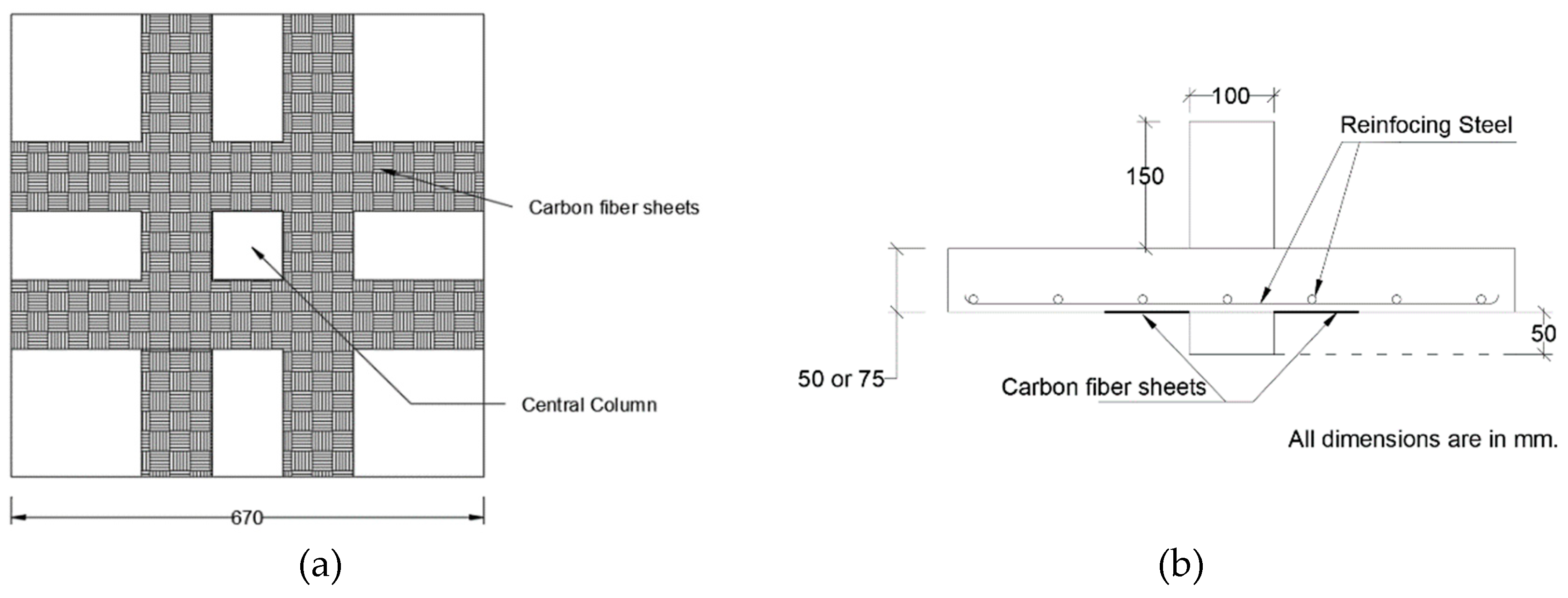
| Harajli and Soudki [27] Specimen size (mm) 670 × 670 × 55 and 670 × 670 × 75 | A1-SA1 | Control CFRP sheet | 31.9 | 49.2 | 1. Flat slab A1-SA1, A2-SA2, B1-SB1, and B2-SB2 are control specimens not strengthened with CFRP strips. Specimen names ending F5, F10, and F15 were reinforced with CFRP strips that are 50 mm, 100 mm, and 150 mm wide, respectively. 2. Increase in two-way shear strength ranged from 17% to 45%, depending on the area of CFRP sheets, slab thickness, and the reinforcement ratio of the slab. 3. In fours specimens, CFRP sheets experienced anchorage failure at the supports due to shearing of a thin concrete layer between the epoxy resin and the concrete surface. 4. Premature bond failure occurred when CFRP was applied in two layers, due to increase in horizontal shear between the CFRP layer and the concrete surface. 6. CFRP reinforcement improves shear strength of slab–column connections restricting the growth of the tensile cracks or increasing the flexural strength of the connections. 7. Use of CFRP sheets increases flexural strength and may modify the failure mode from pure flexural mode to combined flexural-shear mode or pure punching mode. |
| A1-SA1F5 | 29.1 | 47.4 | |||
| A1-SA1F10 | 34.3 | 65.4 | |||
| A1-SA1F15 | 23.5 | 64.1 | |||
| A2-SA2 | 35.5 | 60.5 | |||
| A2-SA2F5 | 31.9 | 70.1 | |||
| A2-SA2F10 | 35.5 | 77.7 | |||
| A2-SA2F15 | 23.5 | 80.0 | |||
| B1-SB1 | 35.5 | 78.8 | |||
| B1-SB1F10 | 31.9 | 114.5 | |||
| B1-SB1F15 | 33.0 | 104.0 | |||
| B1-B1F10(2L) | 34.3 | 107.5 | |||
| B2-SB2 | 29.1 | 122.0 | |||
| B2-SB2F10 | 29.1 | 142.3 | |||
| B2-SB2F15 | 33.0 | 118.6 | |||
| B2-B2F10(2L) | 34.3 | 123.3 | |||
| El-Salakawy et al. [28] Specimen size (mm) 1540 × 1020 × 120 | XXX | GFRP strips vertically around the column | 33.0 | 125 | 1. Use of FRP sheets increased punching shear capacity, flexural stiffness, and delayed opening of flexural cracks. However, failure was mostly due to punching shear. 3. When shear bolts are used along with FRP strips, ductility at the slab–column connection increased and failure mode changed from punching to a flexure. Furthermore, combined FRP sheets and vertical steel bolts increased punching shear strength by 23% to 30%. 4. Punching shear capacities predicted by both ACI 318-02 (2002a) and CSA A23.3-94 (1994) were conservative. |
| SF0 | 31.5 | 110 | |||
| SX-GF | 32.0 | 130 | |||
| SX-CF | 32.0 | 126 | |||
| SX-GF-SB | 40.2 | 170 | |||
| SF-GF | 32.0 | 135 | |||
| SH-GF-SB | 40.2 | 162 | |||
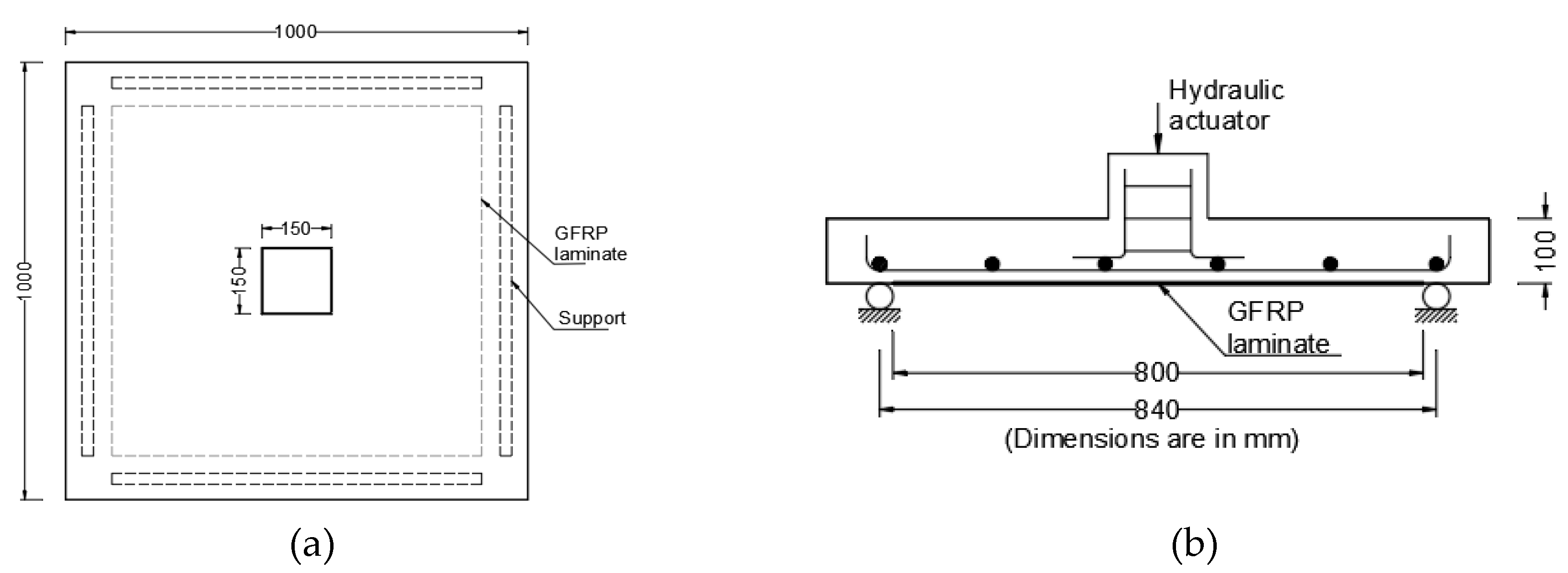
| Chen and Li [29] Specimen size (mm) 1000 × 1000 × 100 | SR1-C1-F0 | GFRP reinforced externally bonded | 16.9 | 103.9 | 1. GFRP laminates increase the punching shear capacity of slab–column connections by functioning as external reinforcement. 2. GFRP laminates are more effective in enhancing the ultimate punching shear capacity in slabs with low concrete compressive strength and reinforcement ratio. 3. For lightly reinforced slabs, GFRP laminates applied to slab–column connection may change flexural punching failure into brittle punching shear failure. 4. Predictions of punching shear based on BS 8110 and the JSCE code were consistent with test results. However, ACI 318 is more conservative. |
| SR1-C1-F1a | 151.6 | ||||
| SR1-C1-F1b | 144.4 | ||||
| SR1-C1-F2a | 217.8 | ||||
| SR1-C1-F2b | 186.4 | ||||
| SR1-C2-F0 | 34.4 | 123.8 | |||
| SR1-C2-F1a | 151.9 | ||||
| SR1-C2-F1b | 208.0 | ||||
| SR1-C2-F2a | 216.8 | ||||
| SR1-C2-F2b | 220.7 | ||||
| SR2-C1-F0 | 16.9 | 146.1 | |||
| SR2-C1-F1a | 188.4 | ||||
| SR2-C1-F1b | 190.8 | ||||
| SR2-C1-F2a | 223.7 | ||||
| SR2-C1-F2b | 224.7 | ||||
| SR2-C2-F0 | 34.4 | 225.7 | |||
| SR2-C2-F1 | 263.9 | ||||
| SR2-C2-F2 | 289.4 | ||||
| Sharaf et al. [31] Specimen size (mm) 1750 × 1750 × 120 | Control | CFRP strips externally bonded | 28 | 421 | 1. Strengthening of slabs with externally bonded CFRP strips delayed the initiation of cracks and controlled their propagation. Nonetheless, all strengthened specimens failed in punching shear mode. 3. The enhancement in punching shear load increased with increase in the area of CFRP reinforcement. 4. The presence of externally bonded CFRP strips reduced the strain in the internal steel reinforced bars. 5. ACI318, BS8110, and CSA codes offered very conservative estimation of punching shear compared to test results. |
| 4-O-CFRP | 25 | 420 | |||
| 4-S-CFRP | 28 | 451 | |||
| 8-O-CFRP | 25 | 456 | |||
| 8-S-CFRP | 25 | 462 | |||
| 8-O&S-CFRP | 28 | 477 | |||
| Esfahani [32] Specimen size (mm) 1000 × 1000 × 100 | R0.8-C25-F0 | CFRP sheets externally bonded | 23 | 138.0 | 1. Using CFRP sheets as flexural reinforcement can increase the punching shear strength of flat slabs, significantly. 2. Comparison between the results shows that cyclic loading decreases the enhancement of punching shear strength. 3. Equations proposed by Iranian Code ABA are similar to the equations presented by ACI Code and result in the same punching shear strength. Among the equations used for punching shear strength prediction, the equation proposed by BS 8110 Code predicted the punching shear strength most accurately with least scatter |
| R0.8-C25-F10 | 191.0 | ||||
| R0.8-C25-F10-CL | 172.0 | ||||
| R0.8-C25-F15 | 208.8 | ||||
| R0.8-C25-F15-CL | 188.0 | ||||
| R1.6-C25-F0 | 210.0 | ||||
| R1.6-C25-F15 | 239.0 | ||||
| R1.6-C25-F15-CL | 198.0 | ||||
| R1.6-C25-F30 | 245.0 | ||||
| R1.6-C25-F30-CL | 210.5 | ||||
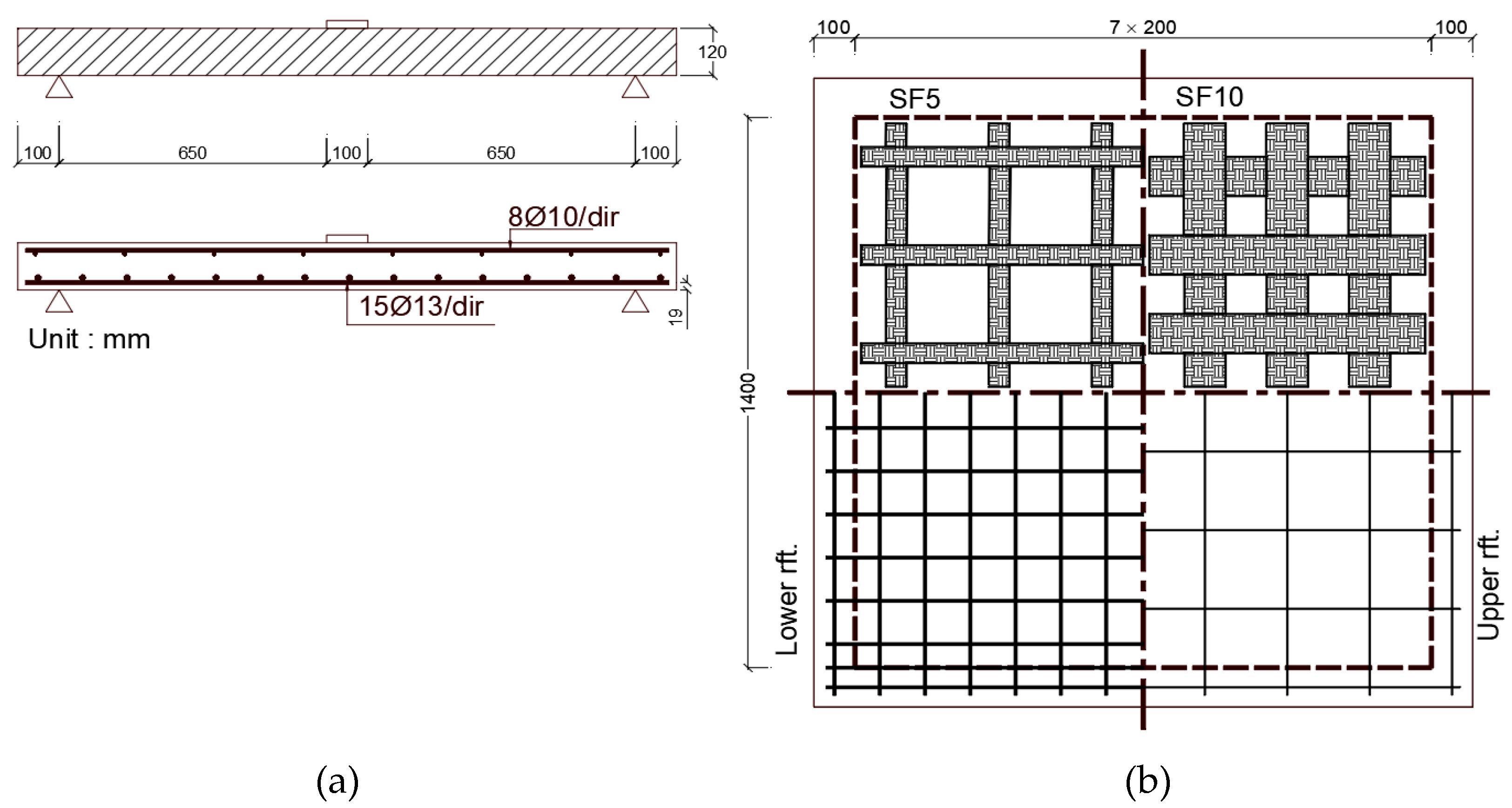
| Farghaly et al. [33] Specimen size (mm) 1600 × 1600 × 120 | SC | CFRP sheets externally bonded | 44.7 | NA | The study was a numerical simulation of CFRP strengthened slab using finite element software developed by the investigators. 1. Stiffness and punching shear capacity increases with area of CFRP strips. The increase in punching shear capacity ranged from 20% to 40% depending on the area of CFRP sheets. 2. The interface between concrete and CFRP strips was modeled with bond interfacial element that accounts for de-bonding failures. The element was used predict the slip profiles along the FRP-concrete interface. 3. Increasing the width of the CFRP sheet results in uniform stress transfer between the strengthening sheets and the concrete contact surface and decreases slip at the CFRP-concrete contact surface. |
| SF5 | 33.5 | 215.3 | |||
| SF10 | 39.6 | 260.6 | |||
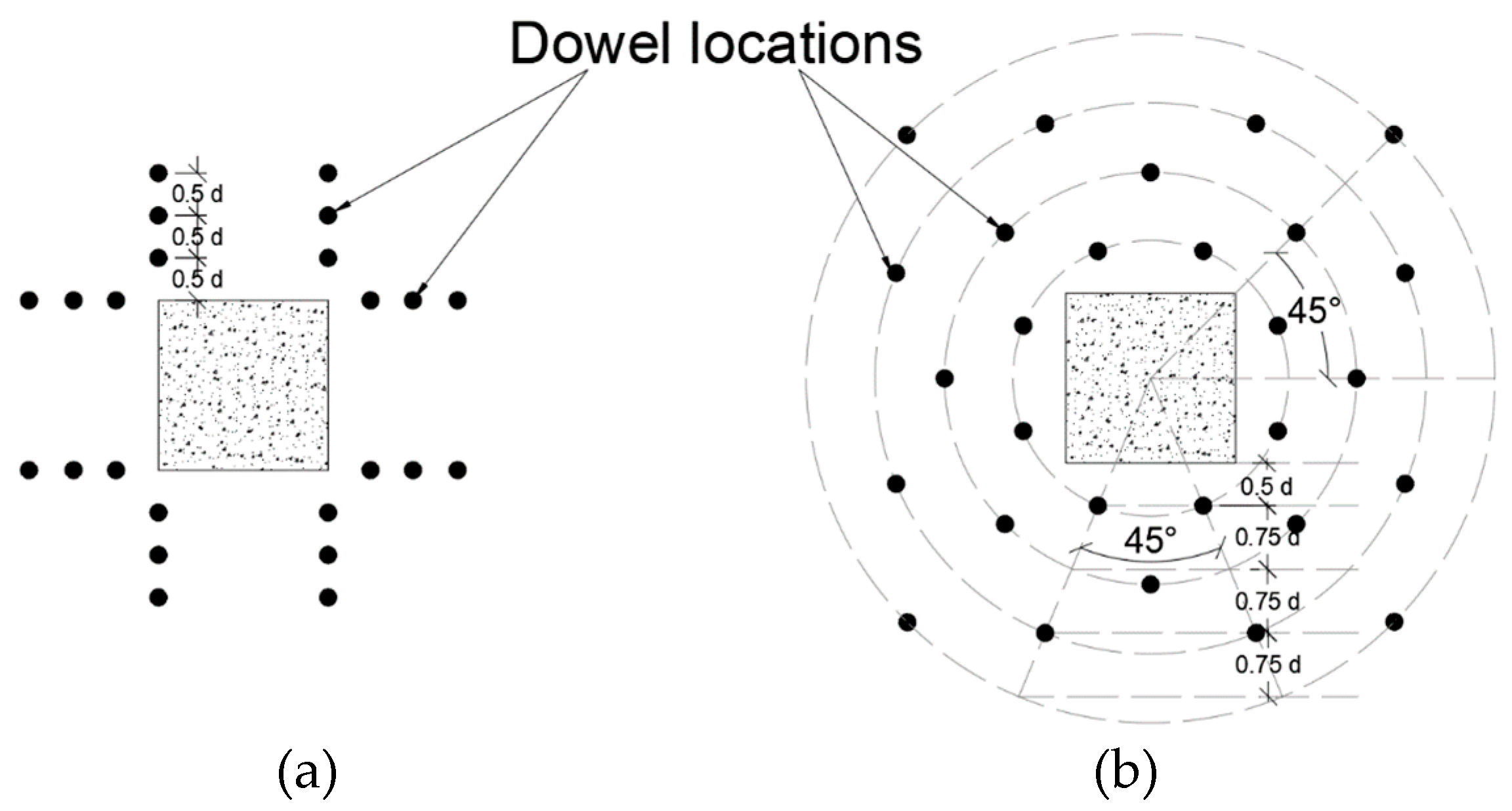
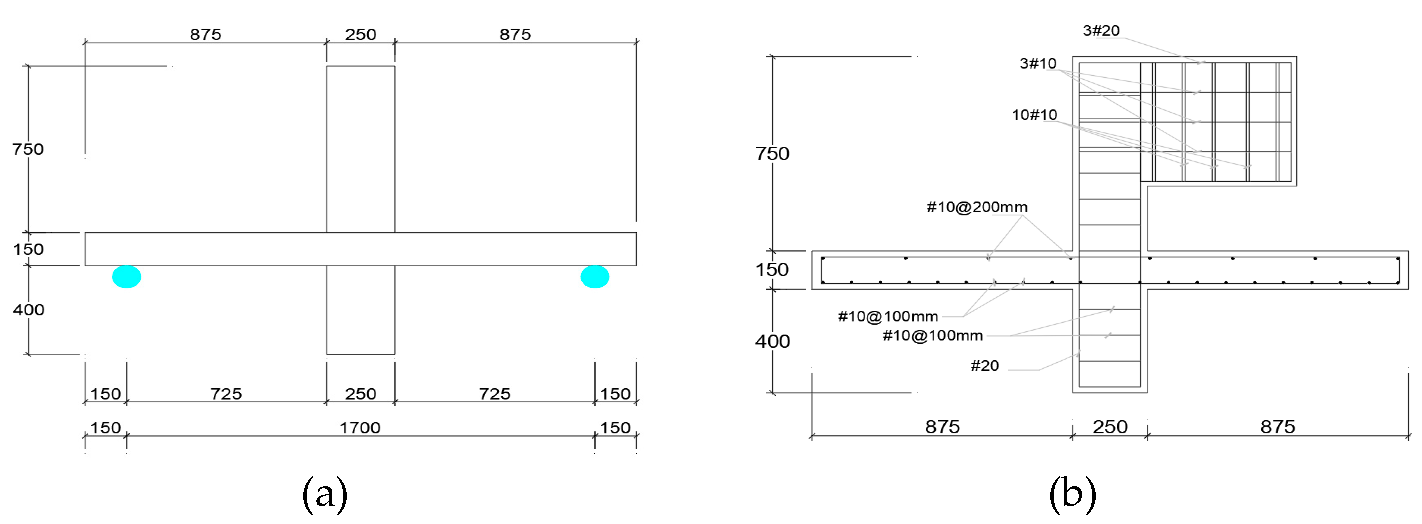
| Erdogan [34] Specimen size (mm) 2000 × 2000 × 150 | R1-A | CFRP | 35 | 457 | The study evaluated effects of CFRP strengthening of slab at supporting column on punching shear capacity and stiffness. Strips were applied vertically through the slab. CFRP strips were applied vertically at constant spacing from the four faces of the supporting column. 1. CFRP strengthening increasing Punching shear strength enhancement 31% to 53% depending on the strengthening scheme. 2. The arrangement and the spacing of the vertical CFRP dowels around the column stub were influential on the failure modes of the specimens 3. CFRP strengthening increasing the post-punching capacity of the specimens about 2.4 times the capacity of the un-strengthened test specimens. 4. ACI 318-08 provides safe estimations for the capacity of the strengthened test specimens in the database. |
| R1 | 32 | 500 | |||
| R2 | 29 | 423 | |||
| R3 | 30 | 414 | |||
| OS13 | 33 | 601 | |||
| OS14 | 26 | 571 | |||
| OS15 | 31 | 656 | |||
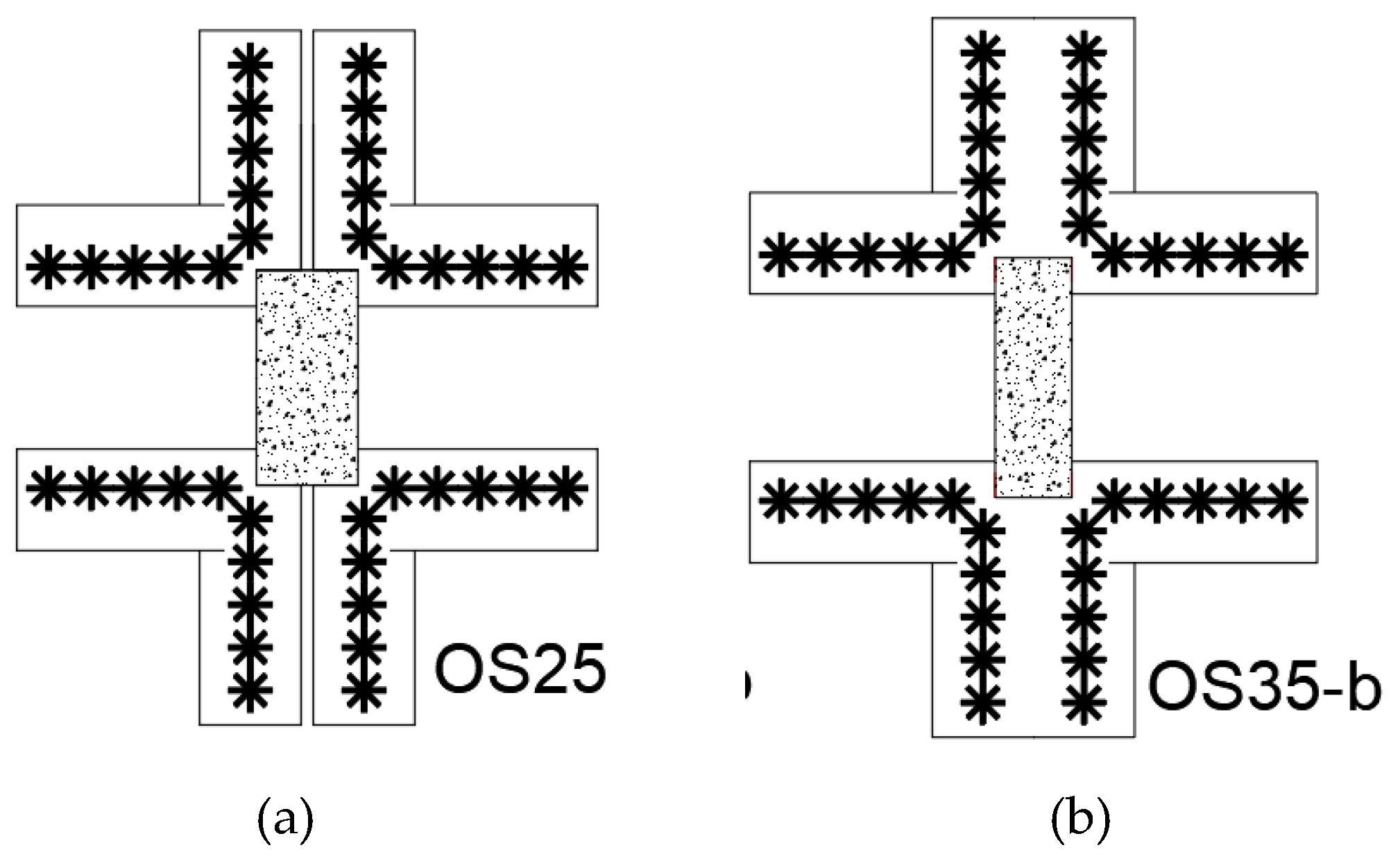
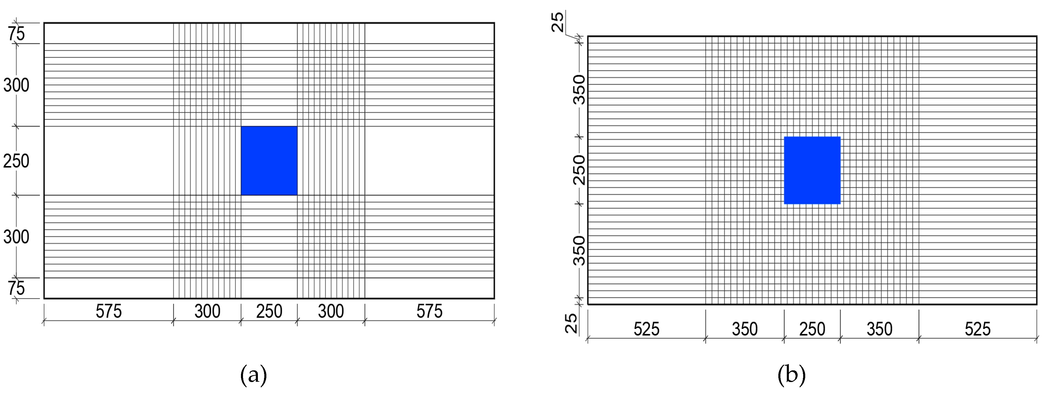
| OS25 | 33 | 649 | |||
| OS25-b | 30 | 571 | |||
| OS35-b | 30 | 564 | |||
| CSWOP | 31 | 594 | |||
| CSWP | 30 | 592 | |||
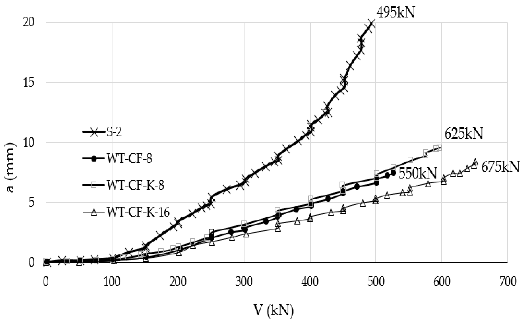
| Urban and Tarka [35] Specimen size (mm) 2300 × 2300 × 180 | S-2 | CFRP strip externally bonded | 38.8 | 495 | The study is an experimental evaluation of the effect of CFRP sheets in enhancing punching shear resistance. 1. Applying bonded CFRP strips without end anchor bolts provides relatively small increase in two-way shear strength, not exceeding 10% compared to the un-strengthened specimen. 2. Adding anchor bolts at the end of the CFRP strips increases punching shear strength significantly compared to the same sample without anchor bolts and compared to un-strengthened specimen. |
| WT-CF-8 | 550 | ||||
| WT-CF-K-8 | 625 | ||||
| WT-CF-K-16 | 675 | ||||
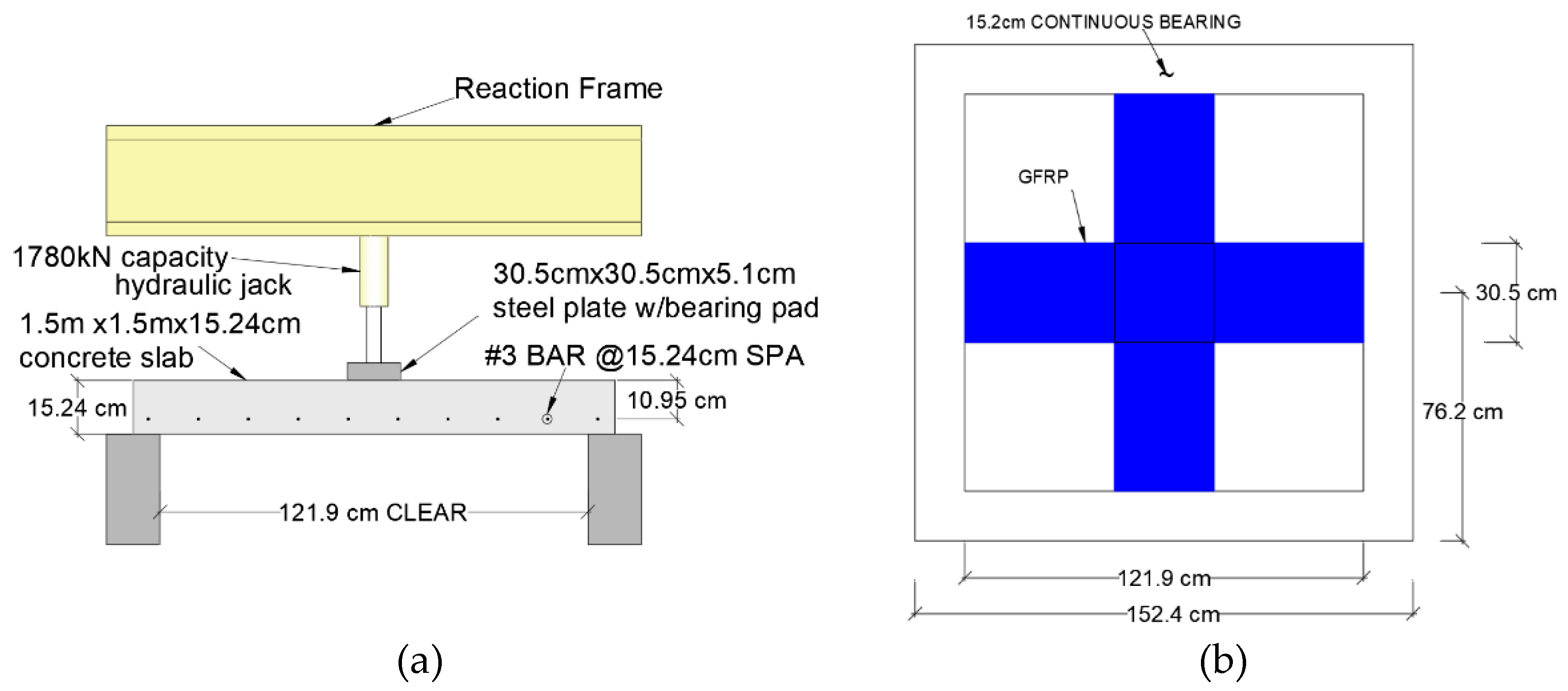
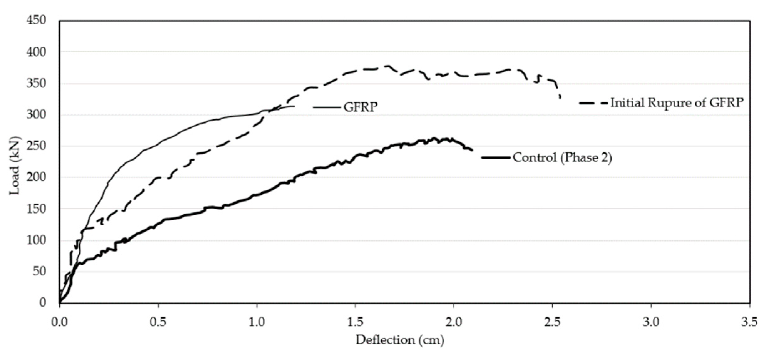
| Radik et al. [38] Specimen size (mm) 1500 × 1500 × 152.4 | Phase1-Control | Polypropylene synthetic GFRP sheet | 27.5 | 256 | 1. The goal of the study is to compare the effectiveness of applying fiber reinforced cement (FRC) layer on the tension side of flat slab in comparison to the effectiveness of GFRP sheet in increasing punching shear strength. The investigators concluded that FRC is more effective that GFRP in enhancing punching shear strength. 2. GFRP increased punching shear strength of flat slab by 24% compared to control flat slab without strengthening. |
| Phase1-2-0.5″ FRC | 302 | ||||
| Phase1-3-1.0″ FRC | 392 | ||||
| Phase1-4-GFRP | 318 | ||||
| Phase2-Control | 263 | ||||
| Phase2-3-.75″ FRC | 315 | ||||
| Phase2-4-GFRP | 383 | ||||
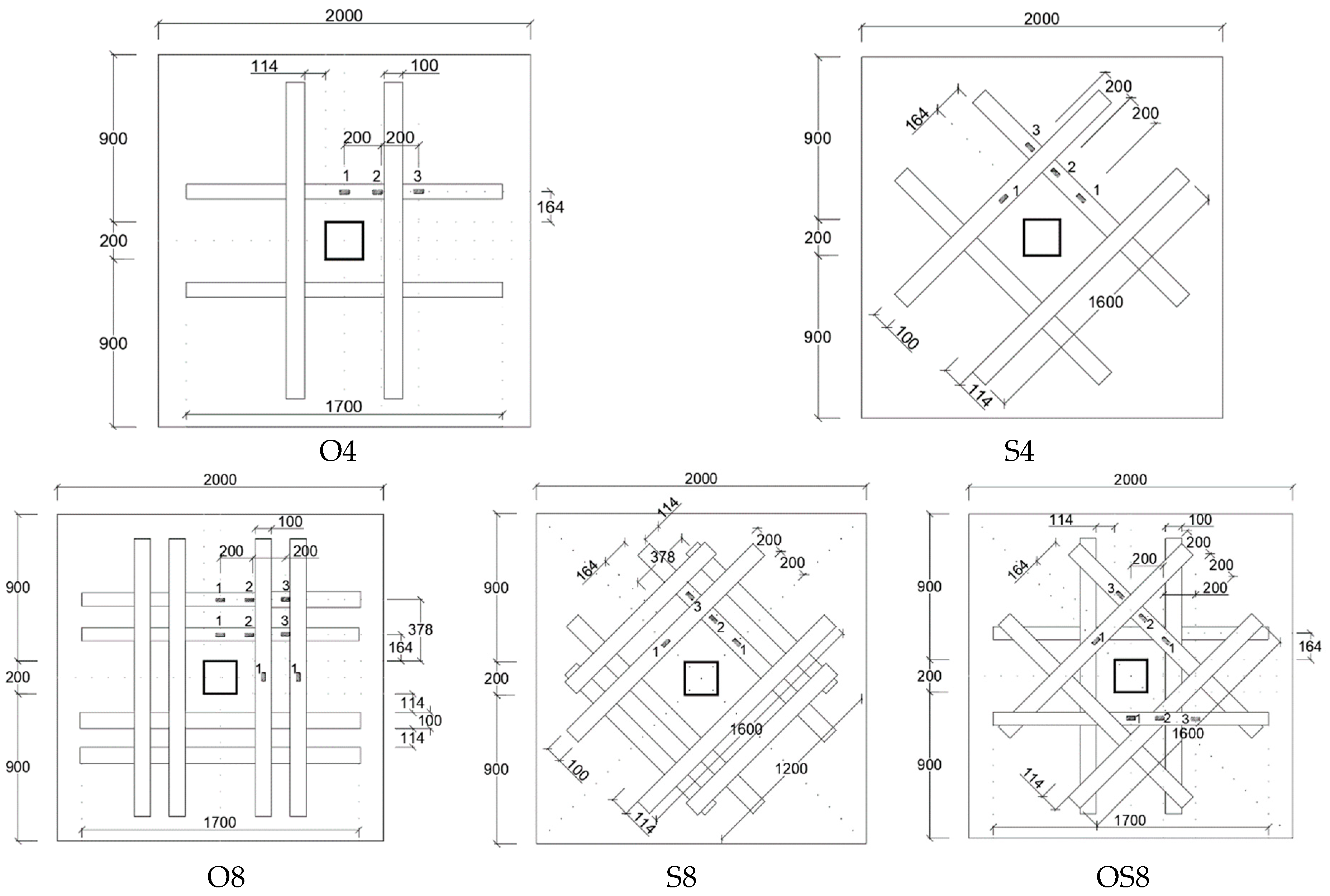
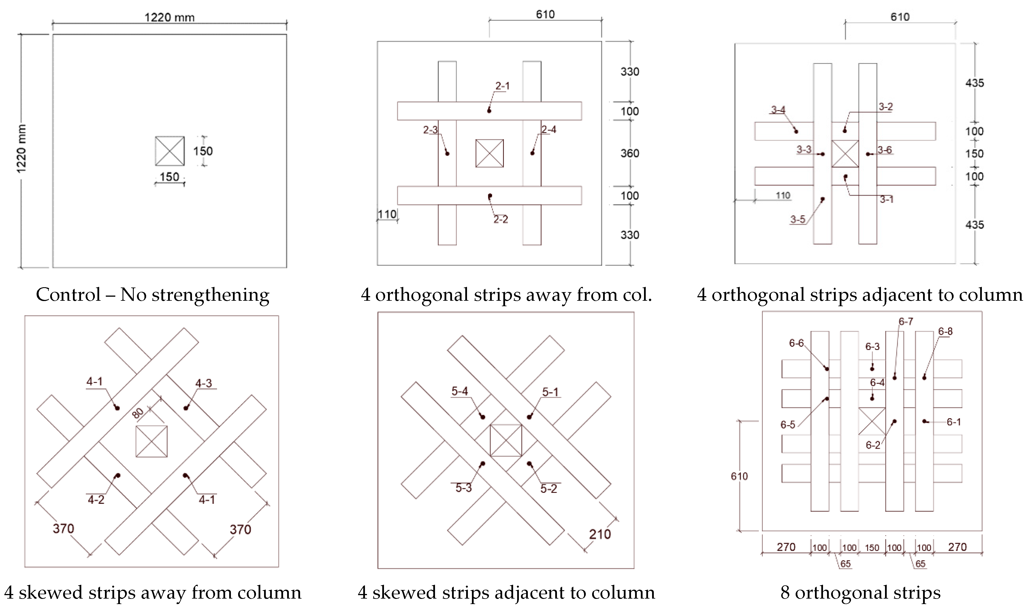
| Soudki et al. [39] Specimen size (mm) 1220 × 1220 × 70 | S | CFRP strip externally bonded | 25.8 | 160.3 | The investigators tested 6 flat slab specimens to determine the effectiveness of externally bonded CFRP strips in enhancing punching shear. 1. All flat slabs failed in punching shear with the CFRP strengthened specimens experiencing ultimate as high as 29% compared to the control flat slab. 2. Higher punching shear capacity was demonstrated by specimens strengthened near the supporting column while higher stiffness is obtained when the CFRP strips are placed near the supporting column. 3. The most effective CFRP strip configuration in enhancing punching shear strength is when the strips are placed further from the supporting column and skewed (with respect to column orientation. 5. Increasing the amount of CFRP strips did not significantly increase the capacity of the slabs. |
| S-4-O-O | 181.0 | ||||
| S-4-O-A | 163.8 | ||||
| S-4-S-O | 206.9 | ||||
| S-4-S-A | 173.7 | ||||
| S-8-O-AO | 192.9 | ||||
| Erdogan et al. [40] Specimen size (mm) 2130 × 2130 × 150 | LC | CFRP stirrups externally bonded | 15.6 | 401 | 1. The application of external CFRP strips proved to be successful in enhancing the punching resistance of rehabilitated and strengthened specimens. 2. It was shown that CFRP-rehabilitated slab–column connections with partial pre-damage may have the potential to exhibit higher shear resistance and stiffness compared to their CFRP strengthened counterparts with no pre-damage. 3. ACI 318 (2011) could be safely used for the design of CFRP rehabilitation of damaged slab–column connections. |
| LS | 696 | ||||
| LF-R | 465 | ||||
| NC | 32.3 | 547 | |||
| NS | 750 | ||||
| ND-R | 940 | ||||
| NF-R | 32.3 | 683 | |||
| Hussein and El-Salakawy [41] Specimen size (mm) 2000 × 1000 × 150 | CON-0 | CFRP sheets externally bonded | 37.3 | 152.2 | 1. The increase of the ultimate strength of CFRP strengthened slab–column connections decrease with the increase of the applied load eccentricity 2. Increasing the applied loading eccentricity markedly decreased the ultimate capacity, pre-yielding stiffness, and ductility of slab–column connections strengthened with external CFRP laminates 3. High reinforcement ratios of external CFRP laminates can result in punching shear failure of slab–column connections subjected to eccentric concentrated loads. |
| STR-0 | 300.0 | ||||
| CON-25 | 47.9 | 135.0 | |||
| STR-25 | 210.0 | ||||
| CON-35 | 53.4 | 130.0 | |||
| STR-35 | 240.0 | ||||
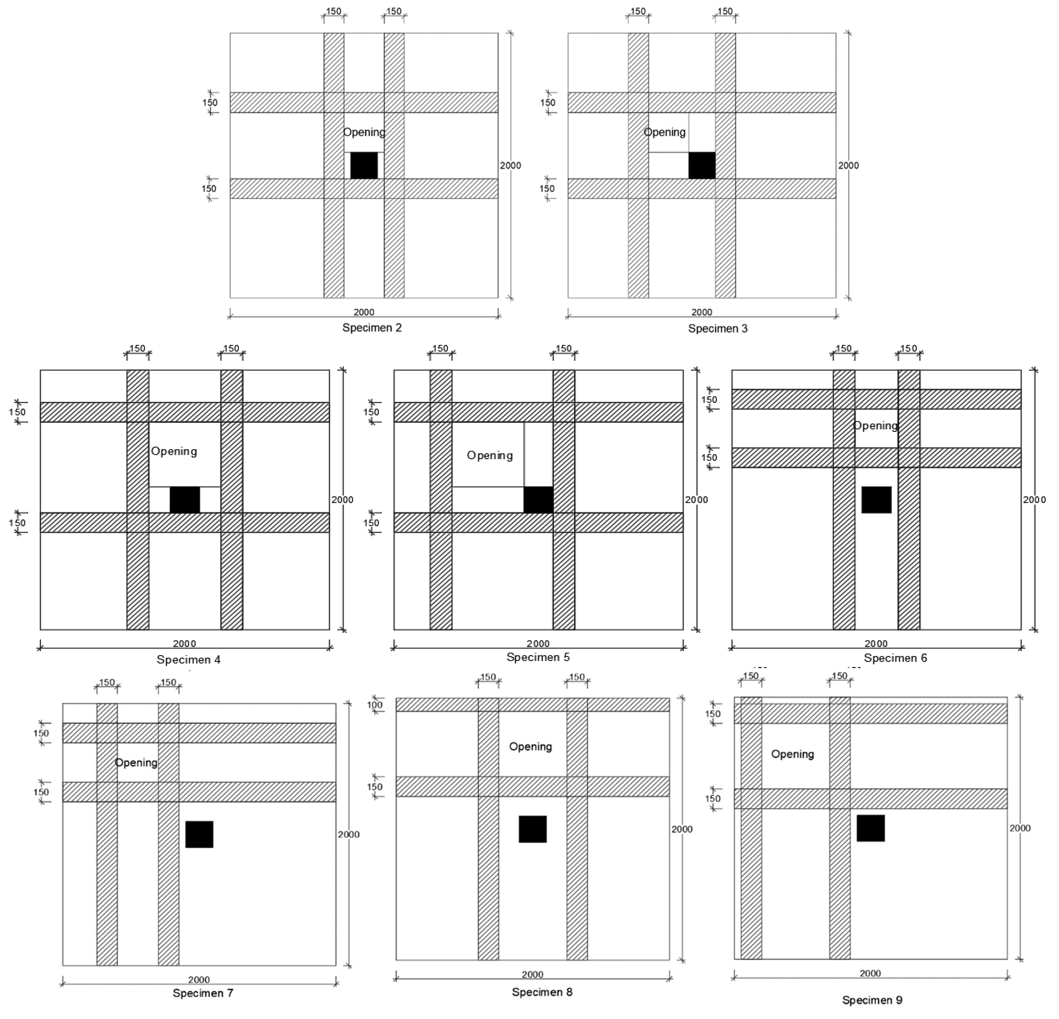
| Durucan and Anil [44] Specimen size (mm) 2000 × 2000 × 120 | 1 (control- no CFRP) | CFRP strips externally bonded | 20.83 | 193.03 | The investigators tested 9 flat slab specimens with openings at various locations in the vicinity of the supporting column. The control specimen was not strengthened while 8 specimens were strengthened with CFRP. 1. CFRP strengthening increases the punching shear capacity in comparison with the control (unstrengthen) specimen by 55% on average. 2. The adverse effect on punching shear capacity of openings near supporting columns is nearly eliminated by using CFRP strips around openings. 3. Highest ultimate load was demonstrated when opening was diagonal with respect to rectangular column, CFRP strips completely surrounded the opening, opening no adjacent to column, and opening not the largest of the test specimens. 4. CFRP strips increased initial elastic stiffness of flat slab specimens by nearly 486% on average, compared to unstrengthen specimens. CFRP strips also increased the maximum displacement at failure. |
| 2 | 20.56 | 161.18 | |||
| 3 | 19.96 | 186.08 | |||
| 4 | 21.23 | 157.71 | |||
| 5 | 19.78 | 173.31 | |||
| 6 | 20.12 | 197.42 | |||
| 7 | 21.45 | 219.36 | |||
| 8 | 20.03 | 190.86 | |||
| 9 | 21.09 | 201.84 | |||
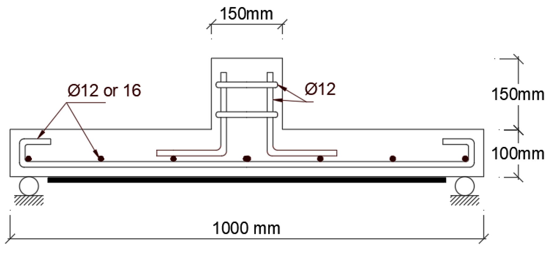
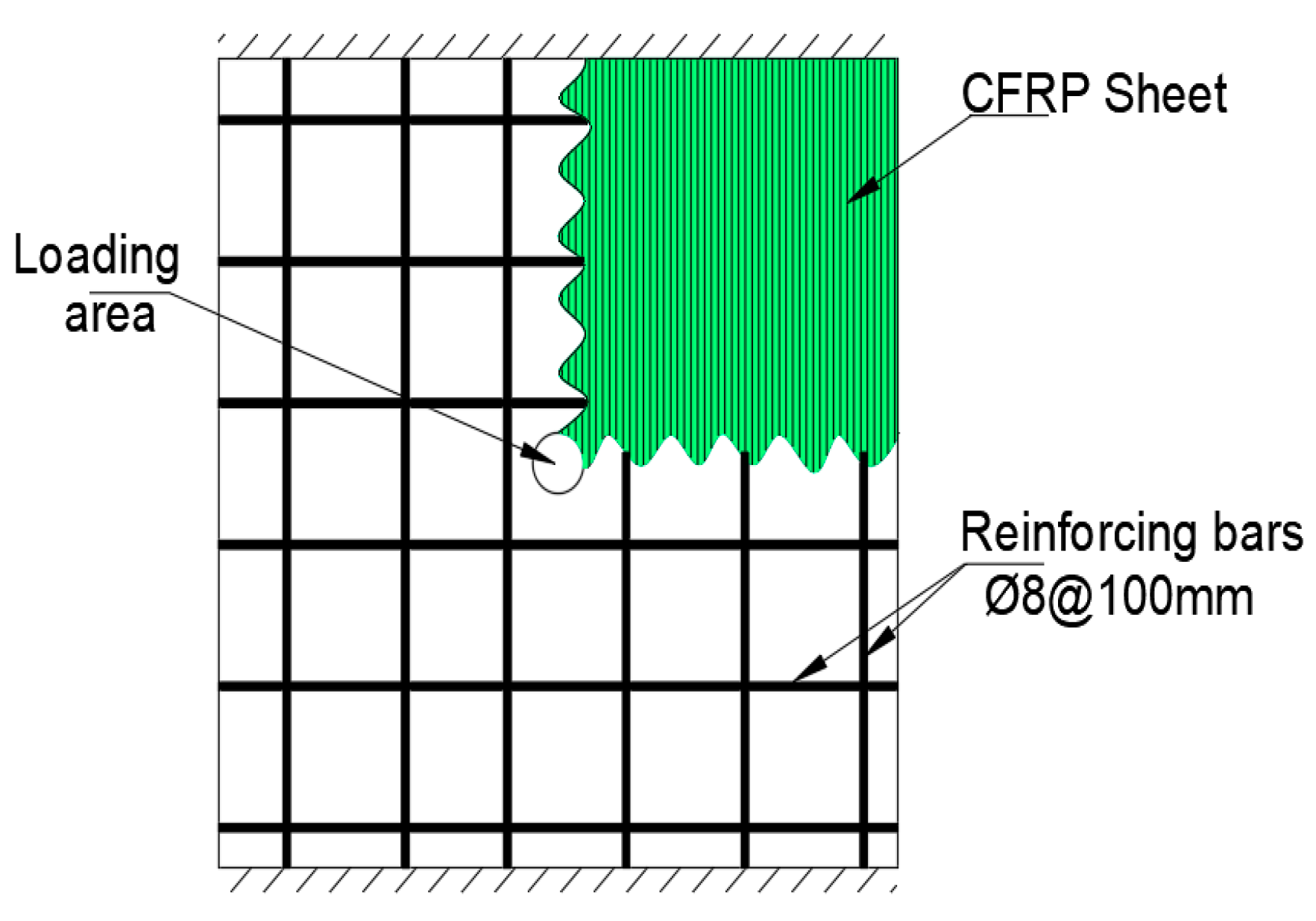
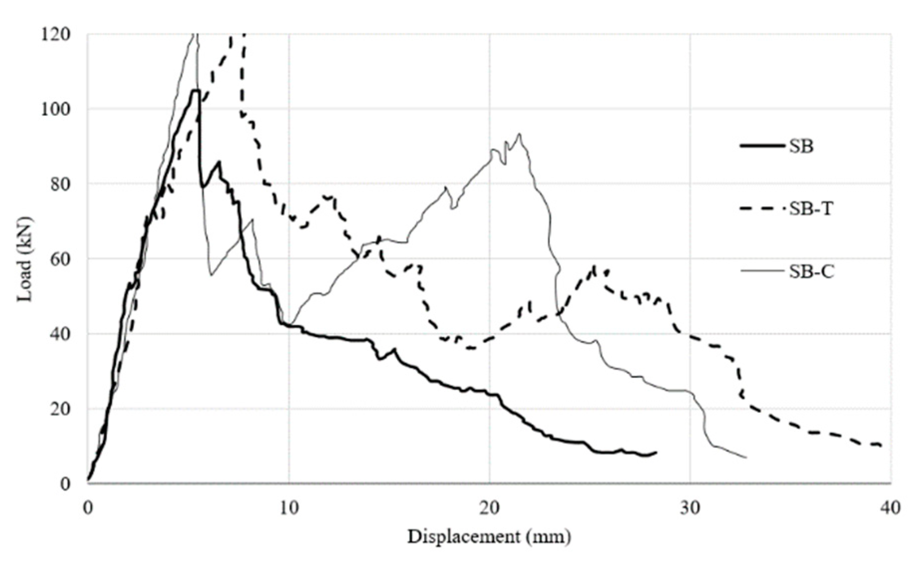
| Abbas et al. [37] Specimen size (mm) 600 × 600 × 90 | SA | CFRP sheets externally bonded | 39.9 | 88.4 | The investigators studied 12 flat slabs supported to span in one direction. Control slabs (SA and SB) were not strengthened. CFRP strengthening with done using single sheet with fibers parallel to the span direction. 1. The load-deflection response curve of CFRP Strengthened one-way specimens was characterized by two peaks compared to the control un-strengthened specimen. The investigators believe the second peak is due to the combined effect of dowel action of rebars, aggregate interlock, and unidirectional strengthening sheet. 2. The CFRP strengthened slabs showed nominal increase in the first peak load (9-18%) but there was significant increase in the second peak load. |
| SA-C | 99.4 | ||||
| SA-T | 96.4 | ||||
| SB | 63.2 | 106.0 | |||
| SB-C | 123.6 | ||||
| SB-T | 125.2 | ||||
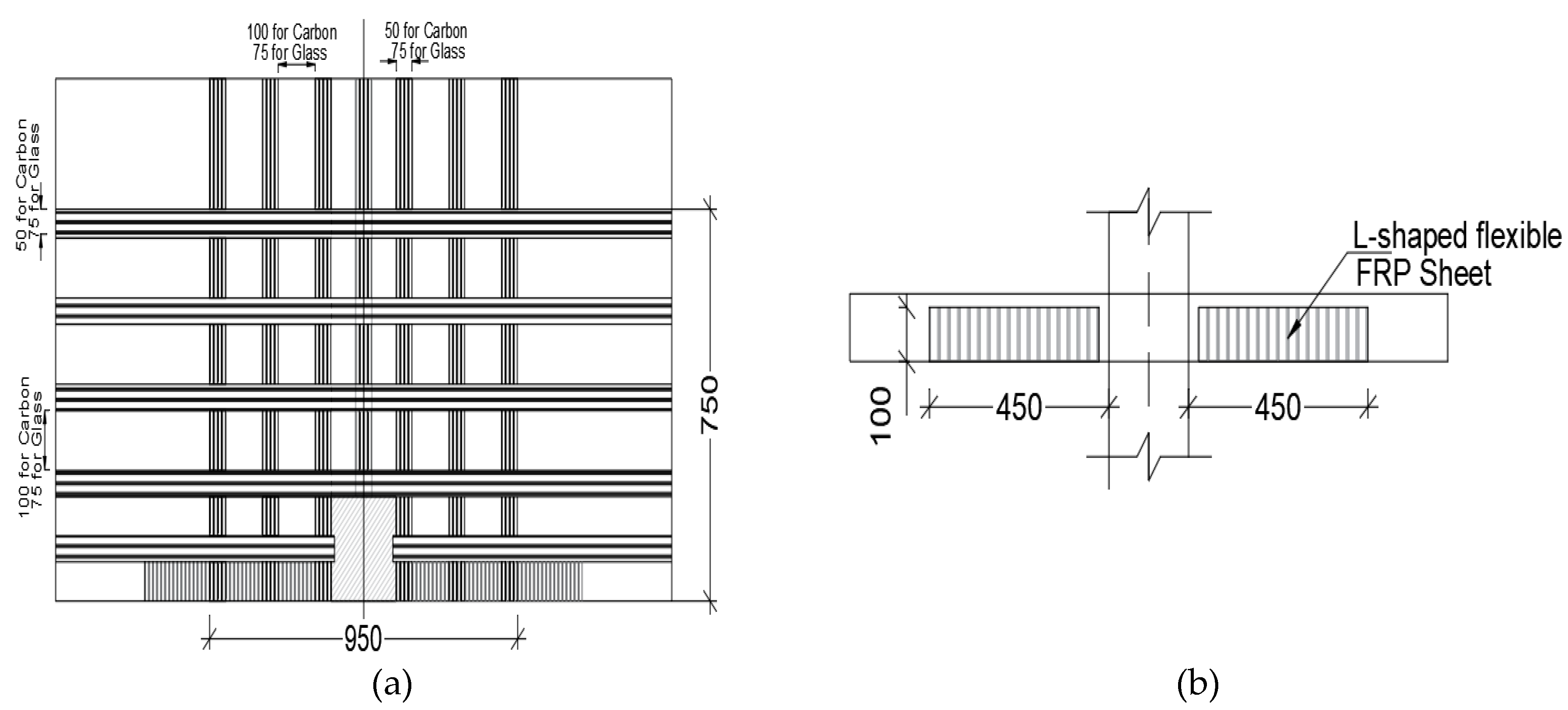
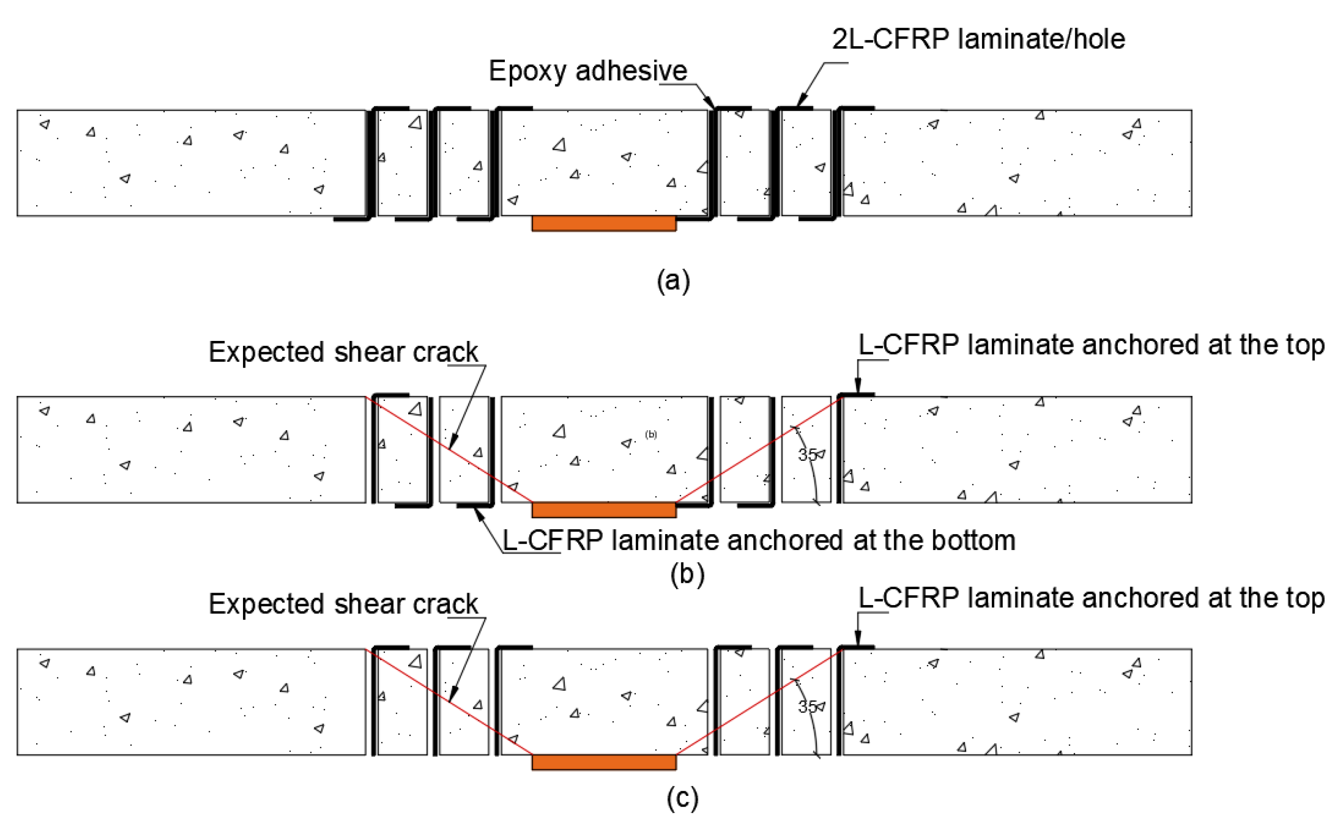
| Saleh et al. [48] Specimen size (mm) 2300 × 2300 × 200 | CS (Control slab) | No CFRP | 25 | 569 | 1. Flat slabs strengthened with L-shaped CFRP strips failed at peak loads that are 97% to 104% higher than the control specimen. 2. CFRP L-shaped strips with configuration SS3 reached a deflection at failure load that is 400% higher than the control slab that was not strengthened. 3. All CFRP strengthened flat slab failed by punching shear at perimeter outside of the reinforced perimeter. Strengthening with L-shaped CFRP strip shifted the failure crack outside of the reinforced zone. 4. EC2 (2004) and ACI318 (2014) were both capable of predicting the capacity the strengthened specimens with reasonable accuracy. |
| Configuration: SS1 | Top & Bottom | 28 | 1121 | ||
| Configuration: SS2 | Bottom/Top | 27 | 1087 | ||
| Configuration: SS3 | Top | 28 | 1163 | ||
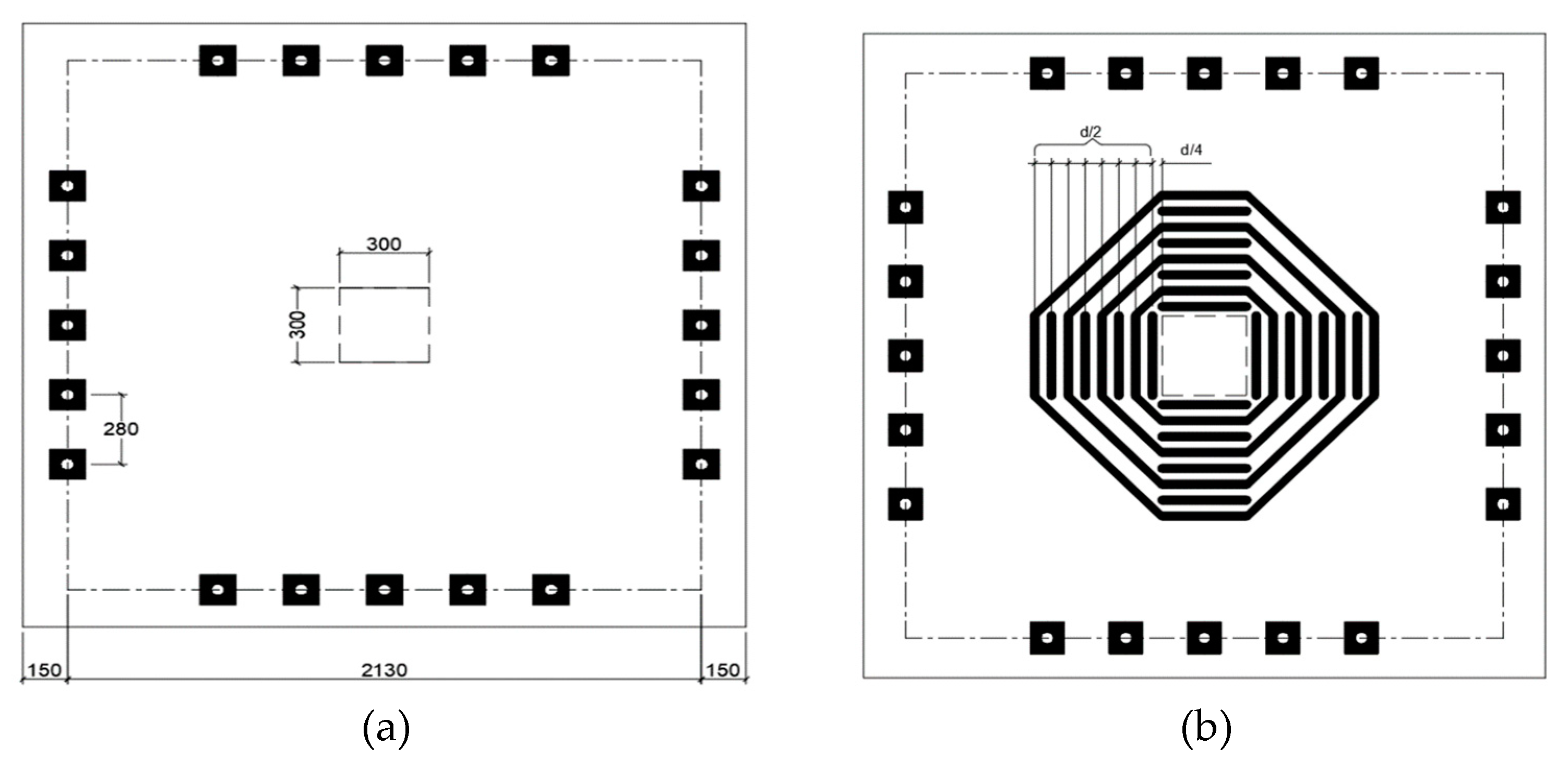
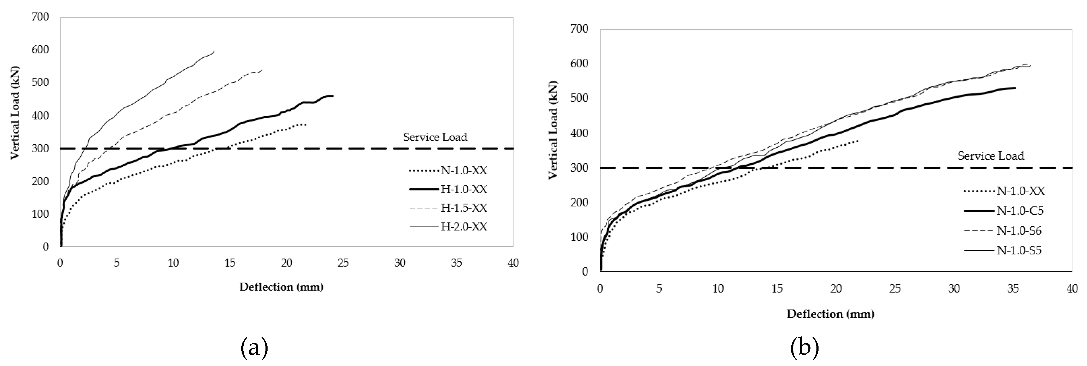
| Hussein and El-Salakawy [41] Specimen size (mm) 2800 × 2800 × 200 | H-1.0-XX | GFRP headed studs GFRP bars corrugated | 80 | 461 | The instigators tested 7 flat slab specimens including three high strength specimens (H-1.0-xx, H-1.5-xx, and H-2.0), and four normal strength specimens (N-1.0-S5, N-1.0-S6, N-1.0-C5, and N-1.0-xx). The high strength specimens were reinforced with variable GFRP bar ratios (1.0%, 1.5%, and 2.0%) and without shear reinforcement. 1. The high-strength concrete specimens (without shear reinforcement) failed in punching shear, without signs of flexural failure. Increase in reinforcement ratio from 1.0%, 1.5%, and 2.0% increased the punching shear capacity by 15% (H-1.5-xx stronger than H-1.0xx) and 27% (H-2.0-xx stronger than H-1.5-xx). 2. The three high strength specimens (80, 84, 87 and MPa) demonstrated better pre-cracking behavior and higher punching shear strength compared to normal-strength concrete specimens (43 MPa). 3. GFRP shear reinforcement controlled widening and propagation of shear cracks and enhanced the post-cracking stiffness which decreased the deflection. This was true for samples reinforced for shear resistance by headed studs (N-10.0-S6, N-1.0-C5) or stirrups (N-1.0-xx). 5. GFRP shear reinforcement not only increased the punching shear capacity, but also increased the failure load and corresponding deflection at failure. |
| H-1.5-XX | 84 | 541 | |||
| H-2.0-XX | 87 | 604 | |||
| N-1.0-S5 | 43 | 595 | |||
| N-1.0-S6 | 43 | 583 | |||
| N-1.0-C5 | 43 | 527 | |||
| N-1.0-XX | 38 | 378 | |||
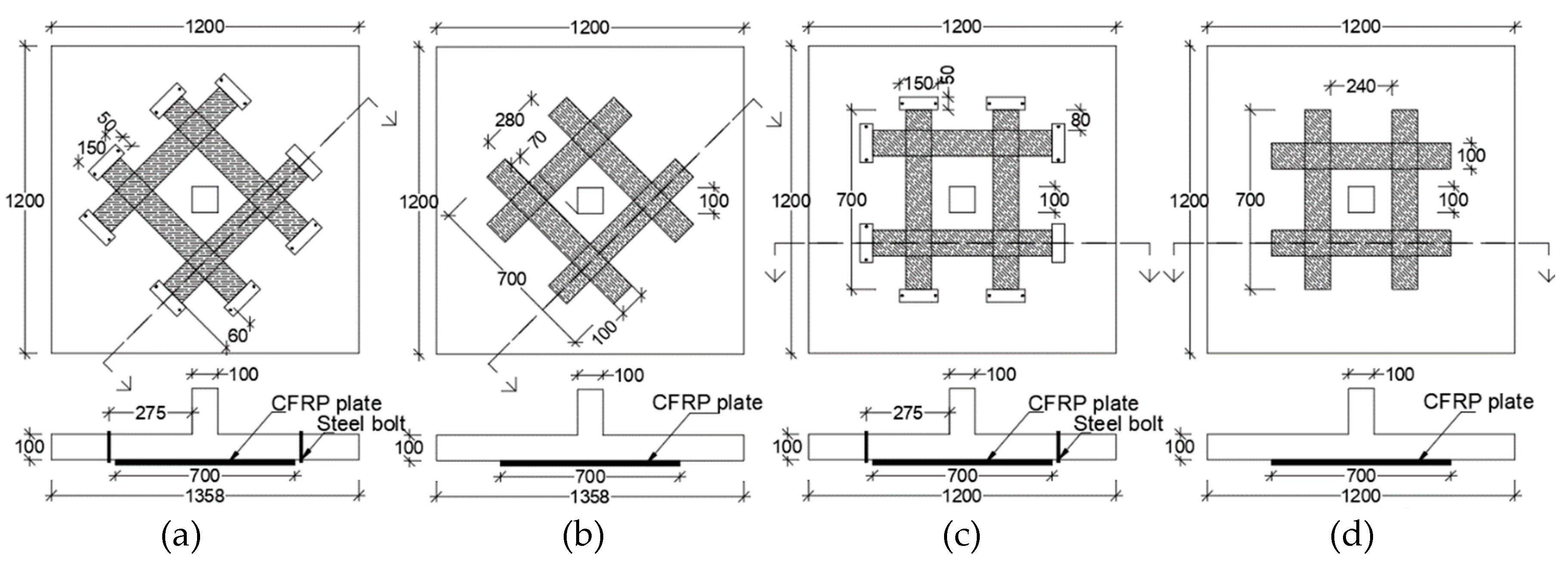
| Silva et al. [43] Specimen size (mm) 1200 × 1200 × 100 | C-a | CFRP Stirrups Externally Bonded | 28.0 | 130 | The investigators studied 8 flat specimens including two control specimens (C-a and C-b) and 6 CFRP strengthened specimens (SE-a, S-a, OE-a, O-a, SE-b, S-b). 1. Skewed placement of CFRP strips with respect to column orientation (SE-a, S-a, SE-b, S-b) at the shear critical area is more effective in enhancing punching shear compared to orthogonal placement. In addition, usage of end anchorage strips (SE-a, SE-b) on skewed CFRP strips enhances strength even more. The highest improvement in punching shear strength was 46% compared to the control specimen without strengthening. 2. Failure patterns suggest that critical punching shear perimeter is located 1.5 to 2.0 times the effective depth from the face of the column, which is consistent with Euro Code 2. 3. Whether CFRP strips are orthogonal or skewed with respect to column orientation, the provision of end anchorage to CFRP strips increases the load carrying capacity. De-bonding of CFRP strips was the failure mode of specimens where end-anchorage of CFRP was not provided. |
| SE-a | 147.15 | ||||
| S-a | 103.0 | ||||
| OE-a | 137.34 | ||||
| O-a | 137.34 | ||||
| C-b | 98.64 | ||||
| SE-b | 147.15 | ||||
| S-b | 122.60 | ||||
| OE-b | 127.53 | ||||
| O-b | 122.63 |
© 2020 by the authors. Licensee MDPI, Basel, Switzerland. This article is an open access article distributed under the terms and conditions of the Creative Commons Attribution (CC BY) license (http://creativecommons.org/licenses/by/4.0/).
Share and Cite
Mohamed, O.A.; Kewalramani, M.; Khattab, R. Fiber Reinforced Polymer Laminates for Strengthening of RC Slabs against Punching Shear: A Review. Polymers 2020, 12, 685. https://doi.org/10.3390/polym12030685
Mohamed OA, Kewalramani M, Khattab R. Fiber Reinforced Polymer Laminates for Strengthening of RC Slabs against Punching Shear: A Review. Polymers. 2020; 12(3):685. https://doi.org/10.3390/polym12030685
Chicago/Turabian StyleMohamed, Osama Ahmed, Manish Kewalramani, and Rania Khattab. 2020. "Fiber Reinforced Polymer Laminates for Strengthening of RC Slabs against Punching Shear: A Review" Polymers 12, no. 3: 685. https://doi.org/10.3390/polym12030685