Article

Intensification of Catalytic Processes through the Pellet Structuring: Steady-State Properties of a Bifunctional Catalyst Pellet Applied to Generic Chemical Reactions and the Direct Synthesis of DME

by
Katarzyna Bizon
*,
Krzysztof Skrzypek-Markiewicz
,
Dominik Pędzich
and
Natalia Reczek
Faculty of Chemical Engineering and Technology, Cracow University of Technology, ul. Warszawska 24, 31-155 Kraków, Poland
*
Author to whom correspondence should be addressed.
Catalysts 2019, 9(12), 1020; https://doi.org/10.3390/catal9121020
Submission received: 16 October 2019 / Revised: 27 November 2019 / Accepted: 28 November 2019 / Published: 3 December 2019
(This article belongs to the Special Issue Computational Chemistry and Catalysis: Prediction and Design)

Abstract

:
Structuring of different types of catalytic active centers at a single-pellet level appears to be a promising and powerful tool for integration and intensification of multistep solid-catalyzed chemical reactions. However, the enhancement in the product yield and selectivity strongly depends on the proper choice of the distribution of different catalysts within the pellet. To demonstrate potential benefits from properly designed catalyst pellet, numerical studies were conducted with the aid of the mathematical model of a single spherical bifunctional catalyst pellet. The analysis was performed both for a system of two generic chemical reactions and for a real process, i.e., direct synthesis of dimethyl ether (DME) from synthesis gas via methanol. Evaluation of the pellet performance was done for three arrangements of the catalytic active sites within the pellet, i.e., a uniform distribution of two types of catalytic active centers in the entire volume of the pellet, and two core–shell structures. It was demonstrated that, especially for the larger pellets typical for fixed-bed applications, the product yield might be significantly improved by selecting proper catalyst arrangements within the pellet.

1. Introduction

Multi- or bifunctional catalyst pellets, also referred to as hybrid pellets, enable integration of more than one functionality in a microscale (Figure 1). The multifunctionality at a pellet level usually consists of the integration of catalytic active sites and adsorbent or two types of catalytic active sites in a single pellet [1,2]. In classical adsorptive reactors, a physical mixture of catalyst and adsorbent particles, bringing the process integration at the entire apparatus level, implements the synergy between chemical reaction and physical adsorption. The application of hybrid pellets may further improve the product yield and selectivity of such multifunctional reactors [3]. Similar benefits may be obtained for multistep solid-catalyzed chemical reactions that require utilization of different types of catalysts [4]. In both cases, the enhancement in the product yield, in comparison to the processes carried out in multifunctional reactors integrating different types of functionalities at the apparatus level (Figure 1) or even carried out in two separate devices, results mainly from the reduction of mass transfer resistances.
Close integration of different functionalities at the apparatus level is now a well-established approach to the process intensification [1,5]. However, the concept of structuring the functionalities at the pellet level has not been entirely examined yet. Integration of the catalytic and adsorptive functionalities has received recently significant attention [2,6]. Evaluation of the performance of bifunctional pellets integrating catalytic and adsorptive functions applied to the Claus process [2], water-gas shift reaction [2,6] and methane steam reforming [6] has revealed the great influence of the spatial arrangement of different functionalities within the pellet, with non-uniform distributions being very often superior over the uniform. The concept of optimal distribution of a single catalytic activity within the pellet was investigated comprehensively in the past [7], but the number of reports dealing with the influence of the spatial distribution of two or more types of catalytic active sites within the pellet on its performance is very limited, even when considering generic systems of chemical reactions [1].
Now, taking into account both the global energy crisis and the attempts of cost reduction via process integration and intensification, much academic and industrial attention is given to a process of direct synthesis of dimethyl ether (DME) from synthesis gas (syngas) on a bifunctional catalyst [8]. Other examples of solid-catalyzed chemical processes that may be conducted using multifunctional catalyst pellets include conversion of syngas into other liquid hydrocarbons and hydroisomerization of n-alkanes [9,10].
Due to high cetane number, relatively low self-ignition temperature and no emission of particulate matter, DME can potentially replace diesel fuel. The properties similar to propane and butane make it also suitable for heating and home cooking [11]. Besides energy application, DME can be used in production of chemicals including propylene and other light olefins [12]. Liquified DME can be applied as a “green” solvent for extraction of lipids, pigments and other high-value products from the biomass [13] or for extraction of spices [14]. Dimethyl ether is also considered as an environment-friendly aerosol and refrigerant [11].
In contrast to the traditional method for the production of DME that consists of two steps, i.e., synthesis of methanol from syngas using a metallic catalyst and its dehydration to DME on an acidic catalyst, the direct synthesis is conducted using bifunctional (hybrid) catalyst pellets containing two types of catalytic active centers. The metallic function used for methanol synthesis is usually composed of CuO, ZnO and Al2O3 or Cr2O3, with copper clusters being the active sites for methanol synthesis and water gas shift reaction, and ZnO maintaining the optimal dispersion of copper metal [11]. The acidic catalysts used for the dehydration of methanol to DME are typically γ-Al2O3 or zeolites such as H-ZSM-5, HY or SAPO [11,15]. Recently, a ferrite zeolite was also investigated as the acidic functionality, demonstrating superiority over other zeolites in terms of methanol conversion and DME selectivity [16,17,18]. Due to the very high importance of this technological process, in the last two decades different preparation methods of bifunctional catalyst pellets for DME synthesis were investigated [4,19,20]. Moreover, the integrated and polygeneration systems based on the direct synthesis of DME were proposed and analyzed in terms of the process performance and economical aspects [21,22]. Nevertheless, while the choice of the chemical species of the catalysts and the preparation methods have been analyzed thoroughly, only recently the spatial distribution of different types of catalytic active centers have started to be explored as an additional design parameter [23].
The purpose of this work is to outline the potential of intensification of solid-catalyzed multistep chemical processes using bifunctional catalyst pellets that integrate two types of catalytic active centers. Due to limited literature reports concerning even generic chemical reactions, the influence of the proper choice of intraparticle distribution of the catalysts on the product yield ad selectivity was first analyzed for a system of two elementary reversible chemical reactions:
A k 1 k 1 B k 2 k 2 C ,
The main purpose of the analysis of generic chemical reactions catalyzed by two types of arbitrary active centers was to give a general insight on the process performance when using a differently structured pellet with a relatively simple model. Then, in the second part of the work, the numerical analysis was extended to a process of direct synthesis of dimethyl ether from synthesis gas. A scheme consisting of a methanol synthesis step over a CuO/ZnO/Al2O3 catalyst [24]:
CO + 2 H 2 CH 3 OH ,
CO 2 + H 2 CO + H 2 O ,
CO 2 + 3 H 2 CH 3 OH + H 2 O ,
followed by the methanol dehydration reaction over an acidic γ-Al2O3 catalyst [25]:
2 CH 3 OH CH 3 OCH 3 + H 2 O ,
was considered when analyzing DME synthesis on a bifunctional catalyst pellet.

2. Results and Discussion

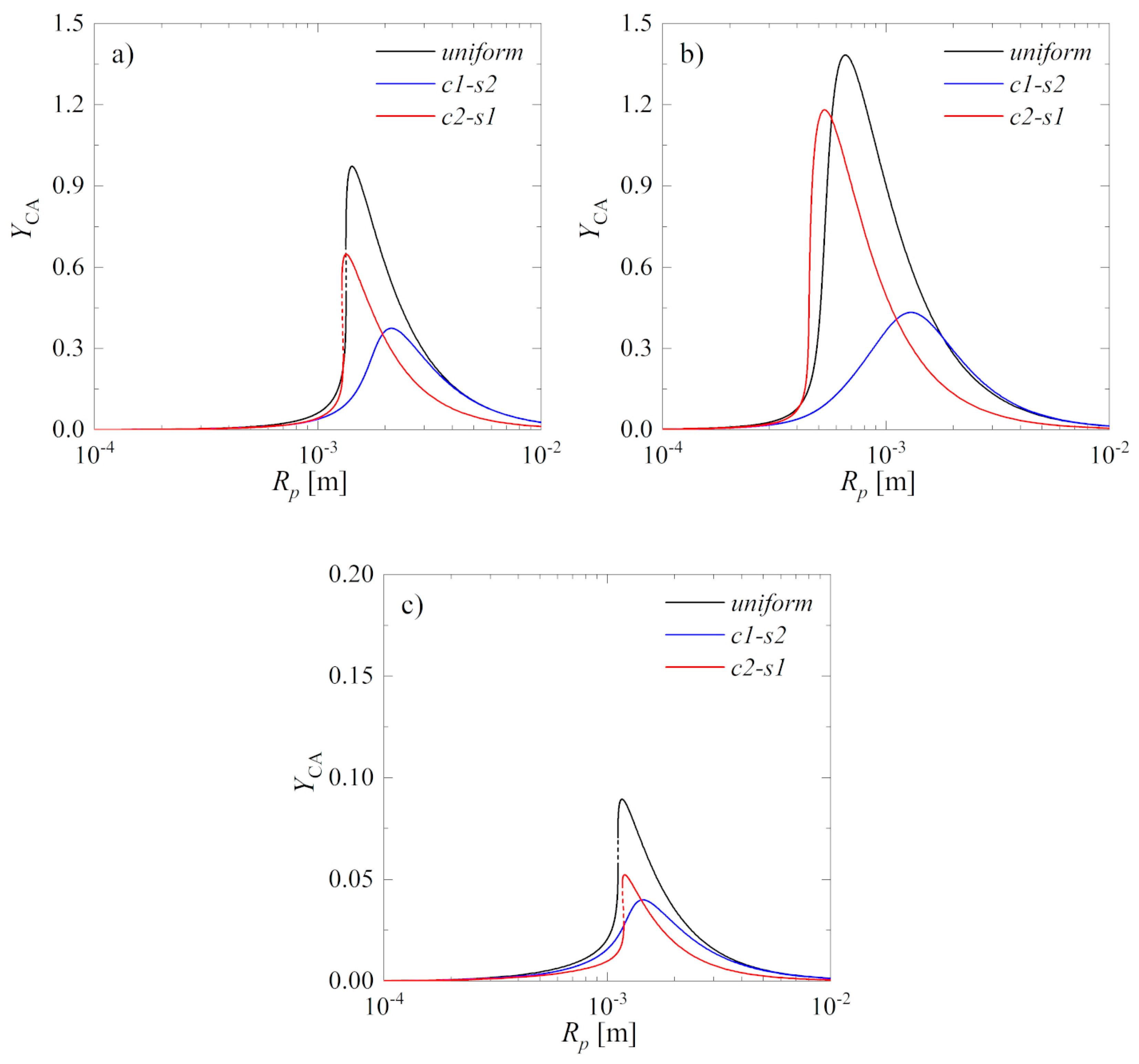
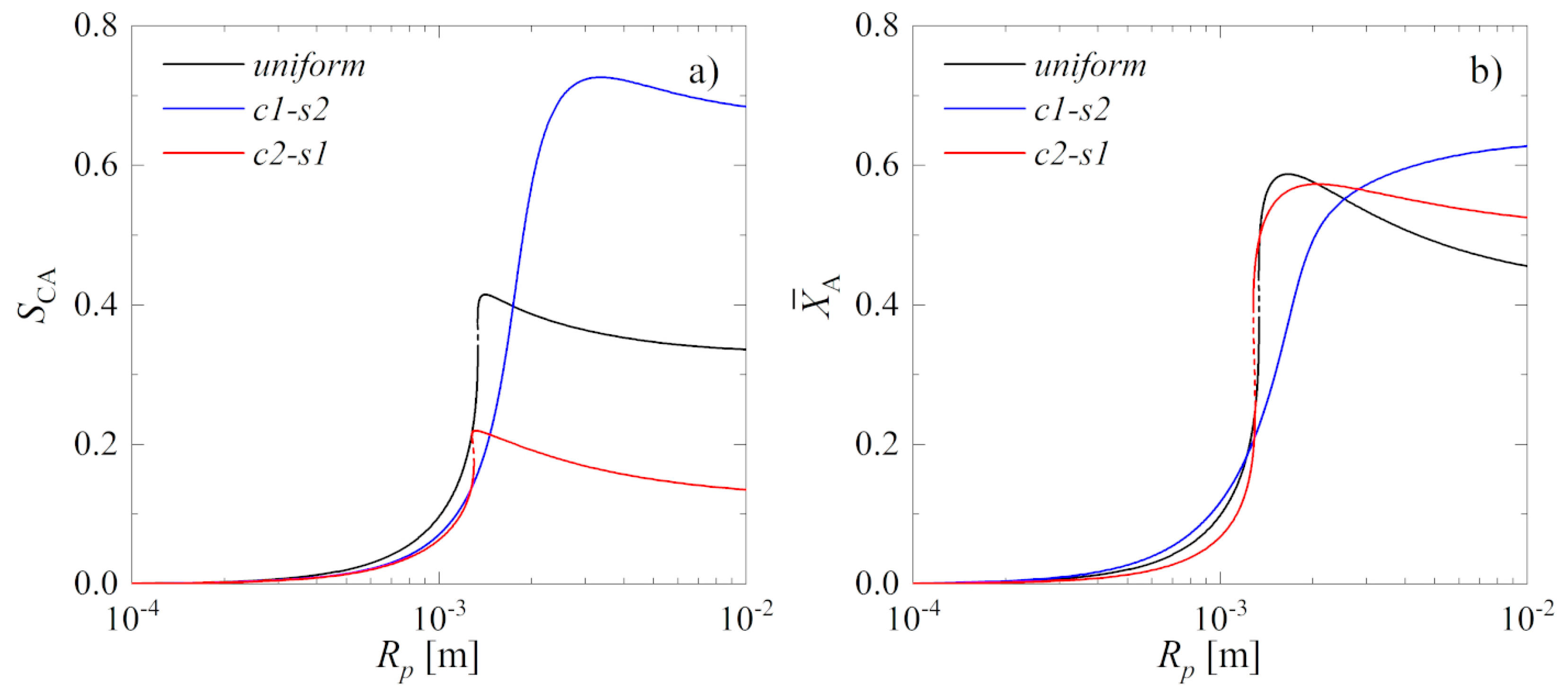
2.1. System of Two Elementary Reversible Chemical Reactions

Three arrangements of catalyst 1 and catalyst 2 within the spherical pellet were examined, including a uniform distribution of the catalysts in the entire volume of the pellet and two non-uniform core–shell distributions. The first non-uniform distribution has catalyst 1 located in the core and catalyst 2 located in the pellet shell, and the second one has inverted arrangement of the catalytic active sites (Figure 2). In all cases, it was assumed that each type of catalyst occupies 0.5 volume fraction of the pellet. Therefore, in the case of the non-uniform core–shell distributions, a dimensionless radius of the pellet core is equal to ζ c o r e = 0.7937 .
It was assumed that for the system of two elementary chemical reactions, the process takes place non-isothermally. The formulation of the model equations and numerical methods used for their resolution are described, respectively, in Section 3.1 and Section 3.3, whereas the values of the model parameters employed in the numerical simulations are reported in Table 1. Due to the generic character of the chemical process examined here, some representative values that may be encountered in solid-catalyzed gas phase chemical reactions were selected [26,27]. The analysis was limited to a single pellet; therefore, the bulk gas concentration adopted for reactant A and intermediate product B, i.e., β A , b u l k = 1 , β B , b u l k = 0 (Table 1) may be interpreted as the simulation of the pellet located near the inlet of a fixed-bed catalytic reactor.
Figure 3 reports solution diagrams of the multifunctional catalyst pellet as a function of the pellet radius, Rp, for fixed values of the other parameters of the model. Abbreviations c1-s2 and c2-s1 denote, respectively, a core–shell structure with catalyst 1 in the core and catalyst 2 in the shell, and a core–shell structure with catalyst 2 in the core and catalyst 1 in the shell. Solid lines indicate stable steady states, whereas dashed lines denote unstable states. Variables β i ( 0 ) , i = A , B and ϑ ( 0 ) , and variables β i ( 1 ) , i = A , B and ϑ ( 1 ) are the dimensionless reactant concentration and temperature at the pellet center ( ζ = 0 ) and at its surface ( ζ = 1 ), respectively. Figure 3b,d,f shows the enlargement of the areas marked, respectively, in Figure 3a,c,e, in which the occurrence of multiple steady-state states for uniform and c2-s1 configuration of the catalysts were observed.
The values of the concentration of the reactants and temperature strongly depend not only on the distribution of the catalytic active sites within the pellet, but also on the pellet radius, Rp. However, for the smallest radii, regardless of how the functionalities, i.e., catalyst 1 and catalyst 2, are distributed within the pellet volume, the values of the reactants concentration and temperature at the pellet center and its surface are almost the same, and—additionally—they are almost equal to those corresponding to the bulk gas conditions (Figure 3a,c,e). This result is quite obvious, because it is well known that for very small pellets both external and internal mass and heat transport resistances become negligible. This means that, for such pellets, the radial distribution of both types of active centers has little, if any, influence on the process performance.
As the pellet radius increases, the relevance of transport resistances also increases, except for the internal heat transport resistance—the almost overlapping steady-state branches ϑ ( 0 ) and ϑ ( 1 ) (Figure 3e,f) correspond to a nearly uniform distribution of the temperature within the pellet. However, while the internal resistance to heat diffusion is negligible in the entire interval of Rp, the temperature gradient at the gas–solid interface starts to increase very rapidly as the radius becomes larger than 10−3 m (Figure 3e).
Evaluation of the concentration solution branches (Figure 3a–d) confirms the importance of different approaches to catalyst integration at the pellet level. The lowest differences between the concentration at the center and at the surface (Figure 3a,c) are observed for the pellet characterized by c2-s1 distribution of the active centers (for intermediate radii), and by uniform distribution (for larger radii). Because of the very short distance between the individual functionalities, uniform structuring of the pellet offers the highest intensification of intraparticle mass transfer. However, this does not result directly in the highest process performance, the reason being that the reaction A B will take place everywhere in the pellet, with significant production of the intermediate product B also near the pellet surface, and this may cause loss of species B to the gas phase for external mass transfer. In this view, a shell containing only active sites for reaction B C may function better, in that it may “trap” species B and convert it into the final product C.
To illustrate the influence of different arrangements of two arbitrary catalytic activities on the intraparticle concentration profiles, representative solutions obtained for the pellet radius R p = 2 × 10 3 m are shown in Figure 4. It is clearly visible that using a different arrangement of the catalytic active centers within the pellet strongly influences the concentration profiles, both qualitatively and quantitatively.
A preliminary analysis of the concentration profiles could suggest that, due to the higher average concentration of B in the pellet with c1-s2 catalysts arrangement, a higher conversion of the intermediate product B (Figure 4b) towards the desired product C is achieved. However, keeping in mind the spherical shape of the pellet, it may be concluded that, in this case, uniform distribution performs best, since for the c1-s2 arrangement the second chemical reaction B C takes place only in the outer shell of the pellet, where the concentration of B is the lowest.
Since it is difficult, and for more complex chemical processes practically impossible, to assess which structure performs best based only on the reactant distribution within the catalyst pellet, it is necessary to define some appropriate quantitative index. The performance of a single catalyst pellet may be measured using various indices including effectiveness factor, selectivity or yield. Under the assumption that production of component C is the objective, the yield of product C with respect to reactant A, Y CA , is employed to assess the pellet performance. Following [7], yield is defined as the ratio between the actual production rate of C and the consumption rate of A in the absence of internal and external transport resistances:
Y CA = 3 0 1 f 2 ( ζ ) k 02 exp ( γ 2 ϑ ( ζ ) ) ( β B ( ζ ) 1 K p 2 β C ( ζ ) ) ζ 2 d ζ k 01 exp ( γ 1 ϑ b u l k ) ( β A , b u l k 1 K p 1 ( T b u l k ) β B , b u l k ) .
Figure 5 reports the yield, Y CA , as a function of the pellet radius Rp, calculated using Equation (6). Figure 5a shows the values of Y CA calculated from the solution presented in Figure 3. Figure 5b,c shows the values of Y CA obtained with one parameter changed with respect to the base case (Table 1), that is the frequency coefficient k 01 increased from 10 6 s 1 to 10 7 s 1 (Figure 5b) and the frequency coefficient k 02 increased from 10 6 s 1 to 10 7 s 1 (Figure 5c), respectively.
For the base-case parameters (Figure 5a), a uniform distribution of the two types of catalytic active centers gives the highest values of the yield of the desired product C with respect to A, Y CA , almost in the whole range of the evaluated pellet radius, Rp. Non-uniform arrangement c2-s1 results perform best in a very narrow region of the solution multiplicity, i.e., for R p 1.3 × 10 3 m. In the case of the largest pellets, the yield obtained using the c1-s2 structure becomes comparable to the Y CA obtained with uniform distribution.
A tenfold increase of the frequency coefficient of the first chemical reaction, k 01 , with respect to the base-case value, has two main effects (Figure 5b): For some values of Rp the yield is greater than unity and for larger pellets c1-s2 structure becomes slightly better, in terms of Y CA , than uniform structure. The first one follows from the temperature of the pellet significantly exceeding the bulk gas temperature (Figure 3e,f) and from the fact that in Y CA , defined by Equation (6), the consumption rate of A is evaluated at the bulk gas conditions. The second effect can be explained as follows: When k 01 > > k 02 and the pellet radius is, approximately, greater than 2 × 10 3 m, the conversion of A towards B in the pellet core with c1-s2 distribution of catalysts is higher than for k 01 = k 02 . Then, despite the relatively long distance between the individual functionalities, the intermediate product B is converted efficiently into the desired product C as it diffuses towards the pellet surface through the relatively thick particle shell.
When k 01 < < k 02 (Figure 5c), and with the other model parameters kept unchanged (Table 1), a uniform arrangement, characterized by the most intimate spatial integration of the both functionalities, performs bests. The higher rate of the second chemical reaction could suggest a greater conversion of B towards C during its diffusion through the thick shell when considering c1-s2 structure and large Rp. However, in this case the limiting reactant is the intermediate product B, being produced from A in the pellet core in a much lower amount than it is for the case presented in Figure 5b.
The intraparticle distribution of the catalytic activities influences also the effectiveness factor of the pellet, and thus the product selectivity. Thus, it is also necessary to analyze the pellet performance in terms of the selectivity of reactant A towards the desired product C, defined as [7]:
S CA = 0 1 f 2 ( ζ ) k 02 exp ( γ 2 ϑ ( ζ ) ) ( β B ( ζ ) 1 K p 2 β C ( ζ ) ) ζ 2 d ζ 0 1 f 1 ( ζ ) k 01 exp ( γ 1 ϑ ( ζ ) ) ( β A ( ζ ) 1 K p 1 β B ( ζ ) ) ζ 2 d ζ ,
Figure 6a reports the selectivity, S CA , determined for the base-case set of parameters (Table 1) as a function of the pellet radius, Rp.
As for the Y CA , the worst performance in terms of the selectivity (Figure 6a) is observed for c2-s1 distribution. For medium to large radii the pellet with c1-s2 distribution of the active centers overperforms significantly uniform distribution in terms of S CA , which can be explained by a “trap” function of the second catalyst located in the shell, increasing substantially the selectivity towards product C. However, up to about R p 3 × 10 3 m the actual conversion degree of reactant A, X ¯ A , calculated as mean integral:
X ¯ A = 3 0 1 ( β A , b u l k β A ( ζ ) β A , b u l k ) ζ 2 d ζ .
for c1-s2 catalyst arrangement is much lower than X ¯ A obtained for uniform distribution of active centers (Figure 6b).

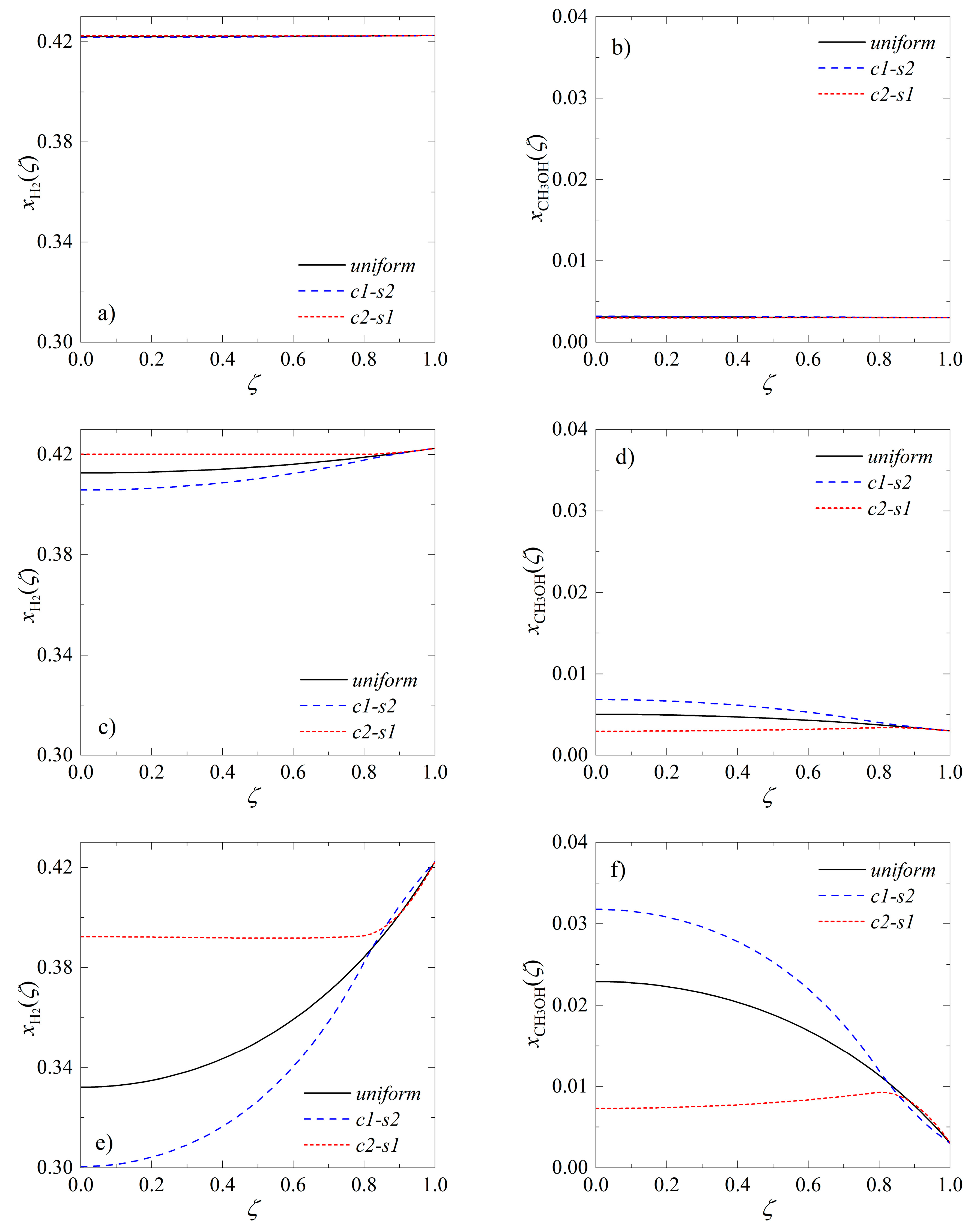
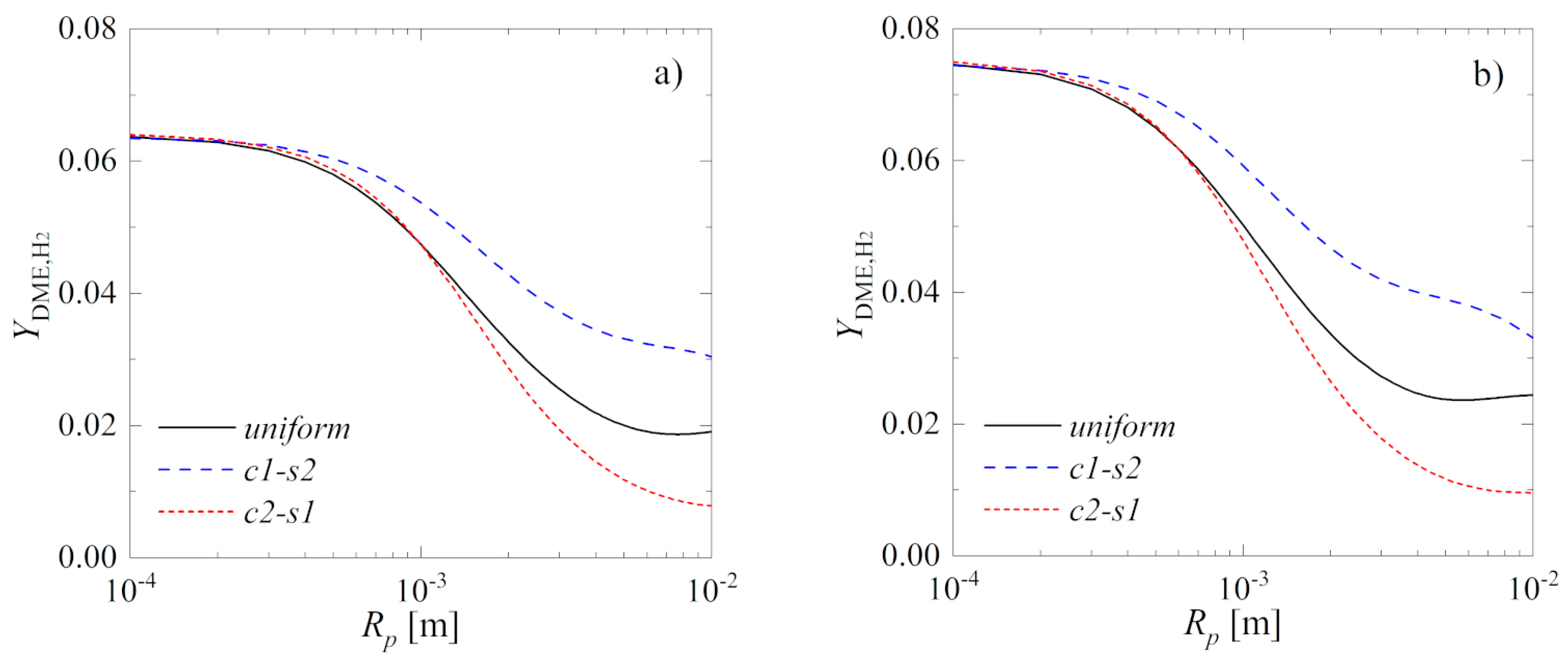
2.2. Direct Synthesis of DME from Syngas

The analysis of the performance of a single bifunctional catalyst performed for a generic system of two consecutive chemical reactions demonstrated that a proper pellet structuring permits enhancing the performance of multistep chemical reactions. For this reason, in the second part of the work, the analysis is extended to a real process, i.e., the direct synthesis of dimethyl ether (DME) from synthesis gas (syngas) via methanol.
The model equations and numerical procedure are described in detail in Section 3.2 and Section 3.3, whereas the model parameters used in the numerical simulations are reported in Table 2 and Appendix A. Based on the literature reports concerning separately methanol synthesis and methanol dehydration steps [28,29] and to reduce the complexity of the pellet model, it was assumed that the pellet is isothermal. As for the case of the system of two elementary reversible chemical reactions, the influence of three arrangements of catalyst 1 (metallic) and catalyst 2 (acidic) within the pellet on the DME yield was evaluated (Figure 2). Moreover, as before, to limit the number of the model parameters analyzed, it was assumed that the pellet volume fraction occupied by each type of the catalytic active sites was equal to 0.5. The performance analysis of the bifunctional pellet was conducted assuming the bulk gas composition equal to the raw, characterized by high content of nitrogen [30], syngas composition (Table 2). Therefore, again, the simulated case corresponds to the behavior of the pellet located near the inlet of a fixed-bed reactor, or, for smaller diameters, to the behavior of the pellet located in a fluidized-bed reactor being at the start-up phase.
Figure 7 shows representative profiles of the hydrogen and methanol molar fractions obtained for T = 493 K using uniform, c1-s2 and c2-s1 arrangement of the metallic and acidic active centers within the pellet of the radius: R p = 2 × 10 4 m (Figure 7a,b), R p = 10 3 m (Figure 7c,d) and R p = 4 × 10 3 m (Figure 7e,f). Computations performed for the smallest of the analyzed radii predict that both hydrogen (Figure 7a) and the intermediate product, i.e., methanol (Figure 7b), are computed as distributed uniformly in the entire volume of the pellet, regardless of the employed arrangements of the catalytic active centers. As the pellet size increases, the catalyst arrangement begins to have an effect on the intraparticle concentration profiles of reactants. Moreover, for the largest radius (Figure 7e,f) the concentration profiles qualitatively resemble those obtained for the system of two elementary chemical reactions (Figure 4). This suggests similar relationships between the values of the product yield that can be achieved using different structures of the pellet.
The yield of the desired product, that is DME, is defined here with respect to the consumption rate of hydrogen as:
Y DME , H 2 = 3 0 1 f 2 ( ζ ) r 4 ( K 2 , x ( ζ ) ) ζ 2 d ζ k = 1 3 | ν k , H 2 | r k ( K 1 , x b u l k ( ζ ) ) ,
As for the case of the system of generic chemical reactions (Equation (6)), the numerator in Equation (9) denotes the actual production of the final product, whereas the denominator is the consumption rate of hydrogen evaluated in the bulk gas conditions.
Figure 8 shows values of the yield of DME with respect to hydrogen, Y DME , H 2 , as a function of particle radius, Rp, calculated for three arrangements of metallic and acidic catalyst and for two values of the process temperature, namely T = 493 K (Figure 8a) and T = 503 K (Figure 8b). The very low values of Y DME , H 2 obtained for all three arrangements result from the assumed concentration of the species in the bulk gas conditions. Additionally, Table 3 reports representative values of Y DME , H 2 , S DME , H 2 and the variation in Y DME , H 2 determined by treating as a reference value the yield of DME achieved, in the same conditions, using uniform distribution of the functionalities within the pellet.
For the smallest radii Y DME , H 2 curves practically overlap (Figure 8), mainly due to little influence of the pellet structure resulting from the negligible resistance to internal mass transfer. For larger radii, the highest yield of DME is predicted for the c1-s2 arrangement of catalytic active centers. Indeed, the variant c1-s2 appears to perform here much better than the uniform one, meaning that the pellet with acidic shell performing as a “trap” for methanol diffusing towards the surface is the best alternative.
The analysis of the temperature influence on the DME yield indicates that, for small to intermediate pellet radii, i.e., R p < 10 3 m (for which the arrangement of two active centers has no significant impact on the Y DME , H 2 ), a temperature increase by 10 K results in a yield enhancement of about 15% (Figure 8a,b). The exothermic character of the methanol synthesis (Equations (2) and (4)) and methanol dehydration (Equation (5)) suggests a decrease in conversion as the temperature increases. However, for the analyzed values of the temperature, the presence of carbon monoxide in a raw syngas may significantly increase the conversion of hydrogen into methanol, even when increasing the process temperature [31].
Representative values of the yield for uniform, c1-s2 and c2-s1 arrangements, and the yield enhancement, determined for c1-s2 and c2-s1 arrangements of two types of catalytic active centers, and related to uniform distribution being here a reference (Table 3), confirm the superiority of the structured pellets with metallic catalyst distributed in the core and acidic catalyst distributed in the shell (i.e., c1-s2). The selectivity of hydrogen towards DME, S DME , H 2 , defined as the ratio of actual production of DME and the actual consumption rate of hydrogen:
S DME , H 2 = 0 1 f 2 ( ζ ) r 4 ( K 2 , x ( ζ ) ) ζ 2 d ζ 0 1 f 1 ( ζ ) ( k = 1 3 | ν k , H 2 | r k ( K 1 , x ( ζ ) ) ) ζ 2 d ζ .
also confirms that the structured c1-s2 pellet is the optimal choice. It must be underlined here that the selectivity calculated from Equation (10) strongly depends on the assumed concentration of the species in the bulk gas corresponding to the vicinity of the reactor inlet. For this reason, much higher values of S DME , H 2 are expected when evaluating the performance of bifunctional pellets on the entire reactor level.

3. Materials and Methods

3.1. Mathematical Model of a Single Bifunctional Catalyst Pellet for a System of Two Elementary Reversible Chemical Reactions

Let us consider a system of two elementary chemical reactions given by Equation (1) taking place in a non-isothermal spherical catalyst pellet of radius Rp that integrates two types of active centers. Under the assumption that pore diffusion occurs with the same, concentration independent, effective diffusivity for all components, the pellet mass and energy balances at steady state are [32]:
D e f f ( d 2 C A d r 2 + 2 r d C A d r ) f 1 ( r ) r 1 ( C A , C B , T ) = 0 ,
D e f f ( d 2 C B d r 2 + 2 r d C B d r ) + f 1 ( r ) r 1 ( C A , C B , T ) f 2 ( r ) r 2 ( C B , C C , T ) = 0 ,
λ e f f ( d 2 T d r 2 + 2 r d T d r ) + f 1 ( r ) r 1 ( C A , C B , T ) ( Δ h 1 ) + f 2 ( r ) r 2 ( C B , C C , T ) ( Δ h 2 ) = 0 ,
where f 1 ( r ) and f 2 ( r ) = 1 f 1 ( r )  denote the pellet volume fraction occupied by catalyst 1 (i.e., the one catalyzing the first step of the process) and catalyst 2 (catalyzing the second step), respectively. The reaction rates, rj are assumed to be of the first order:
r 1 ( C A , C B , T ) = k 1 ( T ) C A k 1 ( T ) C B = k 01 exp ( E 1 R T ) ( C A 1 K p 1 ( T ) C B ) ,
r 2 ( C B , C C , T ) = k 2 ( T ) C B k 2 ( T ) C C = k 02 exp ( E 2 R T ) ( C B 1 K p 2 ( T ) C C ) ,
and K p j is the equilibrium constant for reaction j = 1 , 2 . Due to generic character of the scheme of chemical reactions analyzed here, the temperature dependence of the equilibrium constants is expressed in the following simplified form [33]:
K p j ( T ) = exp ( Δ s j T Δ h j R T ) , j = 1 , 2 .
Assuming spherical symmetry of the concentration and temperature profiles within the catalyst pellet, the following Neumann boundary conditions are imposed at the pellet center:
d C i d r | r = 0 = 0 , i = A , B ; d T d r | r = 0 = 0 .
Accounting for external resistance to mass and heat transfer and assuming that external mass transfer coefficients are the same for all components, Robin boundary conditions at the pellet surface are written as:
D e f f d C i d r | r = R p = k m ( C b u l k , i C i ( R p ) ) , i = A , B ; λ e f f d T d r | r = R p = α q ( T b u l k T ( R p ) ) .
After introducing the dimensionless variables:
β A = C A C r e f , β B = C B C r e f , ϑ = T T r e f , ζ = r R p [ 0 , 1 ] ,
the pellet model (Equations (11)–(13)) can be recast as:
d 2 β A d ζ 2 + 2 ζ d β A d ζ Φ 1 2 f 1 ( ζ ) r ^ 1 ( β A , β B , ϑ ) r ^ 1 , r e f = 0 ,
d 2 β B d ζ 2 + 2 ζ d β B d ζ + Φ 1 2 f 1 ( ζ ) r ^ 1 ( β A , β B , ϑ ) r ^ 1 , r e f Φ 2 2 f 2 ( ζ ) r ^ 2 ( β A , β B , ϑ ) r ^ 2 , r e f = 0 ,
d 2 ϑ d ζ 2 + 2 ζ d ϑ d ζ + Φ 1 2 δ 1 f 1 ( ζ ) r ^ 1 ( β A , β B , ϑ ) r ^ 1 , r e f + Φ 2 2 δ 2 f 2 ( ζ ) r ^ 2 ( β A , β B , ϑ ) r ^ 2 , r e f = 0 .
where:
r ^ 1 ( β A , β B , ϑ ) = k 01 exp ( γ 1 ϑ ) ( β A 1 K p 1 β B ) , r ^ 2 ( β B , β C , ϑ ) = k 02 exp ( γ 2 ϑ ) ( β B 1 K p 2 β C ) ,
r ^ j , r e f = k 0 j exp ( γ j ) ( 1 + 1 K p j ( T r e f ) ) , Φ j 2 = R p 2 r ^ j , r e f D e f f , γ j = E j R T r e f , δ j = D e f f ( Δ h j ) C r e f λ e f f T r e f , j = 1 , 2 .
The plus sign in the reference reaction rate, r ^ j , r e f , i.e., the rate evaluated at bulk gas conditions, results from the definition of the Thiele modulus, Ф, proposed in [32] for reversible chemical reaction. Moreover, considering that the process analyzed here is equimolar, the dimensionless concentration, β i , is equivalent to molar fraction if C r e f = C t o t .
The boundary conditions (Equations (17) and (18)) associated with the pellet mass and energy balances written in terms of dimensionless variables are:
d β i d ζ | ζ = 0 = 0 , d β i d ζ | ζ = 1 = Bi m ( β i , b u l k β i ( 1 ) ) , i = A , B ,
d ϑ d ζ | ζ = 0 = 0 , d ϑ d ζ | ζ = 1 = Bi q ( ϑ b u l k ϑ ( 1 ) ) ,
where the mass and heat Biot numbers are defined, respectively, as:
Bi m = k m R p D e f f , Bi q = α q R p λ e f f .

3.2. Mathematical Model of a Single Bifunctional Catalyst Pellet for a Direct Synthesis of DME from Syngas

The kinetic model proposed in [24] describes the methanol synthesis step:
r 1 = k 1 K CO ( p CO p H 2 3 / 2 p CH 3 OH   / ( p H 2 1 / 2 K p 1 o ) ) ( 1 + K CO p CO + K CO 2 p CO 2 ) ( p H 2 1 / 2 + ( K H 2 O / K H 2 1 / 2 ) p H 2 O ) ,
r 2 = k 2 K CO 2 ( p CO 2 p H 2 p H 2 O p CO / K p 2 o ) ( 1 + K CO p CO + K CO 2 p CO 2 ) ( p H 2 1 / 2 + ( K H 2 O / K H 2 1 / 2 ) p H 2 O ) ,
r 3 = k 3 K CO 2 ( p CO 2 p H 2 3 / 2 p CH 3 OH p H 2 O / ( p H 2 3 / 2 K p 3 o ) ) ( 1 + K CO p CO + K CO 2 p CO 2 ) ( p H 2 1 / 2 + ( K H 2 O / K H 2 1 / 2 ) p H 2 O ) ,
whereas the kinetic rate expression selected for methanol dehydration is as follows [25]:
r 4 = k 4 K CH 3 OH 2 ( C CH 3 OH 2 C H 2 O C DME / K p ) ( 1 + 2 K CH 3 OH C CH 3 OH + K H 2 O C H 2 O ) 4 .
The formulas and parameters used to calculate the kinetic parameters and the equilibrium constants appearing in Equations (28)–(31) are reported in Appendix A.
To reduce the complexity of the pellet model, it is assumed that the process takes place isothermally and that the ideal gas law is obeyed. Following [28,34], the continuity equation and species mass balance for components i = 1 , 2 , , K 1 are given, respectively, as:
ε p C t + 1 r 2 r ( r 2 u C ) = i = 1 K S i ,
ε p t ( C x i ) + 1 r 2 r ( r 2 u C x i ) = 1 r 2 r ( r 2 J i ) + S i ,
with the source term, S i , defined as:
S i = f 1 ( 1 ε p ) ρ p k = 1 3 ν k , i r i + f 2 ( 1 ε p ) ρ p ν 4 , i r 4 , i = 1 , 2 , , K .
where f 1 ( r ) and f 2 ( r ) denote the pellet volume fraction occupied, respectively, by metallic (catalyst 1) and acidic (catalyst 2) catalyst.
Making use of the continuity Equation (32), and assuming steady-state conditions and constant pressure within the pellet (i.e., no viscous flow, thus considering isothermal conditions and also constant concentration), the species mass balance for components i = 1 , 2 , , K 1 (Equation (33)) can be simplified into the following form:
1 r 2 d d r ( r 2 J i ) + S i i = 1 K S i = 0 ,
whereas the equation delivering component i = K is simply given by:
i = 1 K x i = 1 .
The molecular diffusion fluxes, J i :
J i = C D i , e f f d x i d r , i = 1 , 2 , , K 1 and i = 1 K J i = 0 ,
are determined according to Wilke–Bosanquet model for multicomponent mass diffusion that combines bulk and Knudsen flux using the Fickian formulation [35]:
1 D i = 1 D i , W + 1 D i , K ,
D i , W = 1 x i j = 1 j i K x j / D i , j ,
D i , K = 97 2 d p o r e T M i ,
with binary diffusion coefficients, D i j (note that for ideal gas conditions D i , j = D i , j = D i , j o ), calculated according to the Chapman–Enskog kinetic theory [36]:
D i , j o = 1.883 10 22 T 1.5 p σ i j 2 Ω D 1 M i + 1 M j .
Accounting further for the pores geometry, the effective diffusion coefficient of a component i in a multicomponent mixture, D i , e f f , is calculated as [35]:
D i , e f f = ε p τ D i .
The boundary conditions associated with the system of 2 × ( K 1 ) first-order differential equations (Equations (35) and (37)) are:
J i ( r = 0 ) = 0 , i = 1 , 2 , , K 1 ,
J i ( r = R p ) = k i , m ( C i , b u l k C x i ( R p ) ) .
where the mass transfer coefficients, k i , m , are calculated from the Sherwood number correlation for a fixed bed [37]:
Sh = 2 + 1.8 Re p 0.5 Sc 0.33 .
Introduction of the expression describing the molecular flux (Equation (37)) into the species mass balance (Equation (35)) enables rewriting the pellet model in a form analogous to Equation (11), namely:
C d d r ( D i , e f f ( x ) d x i d r ) + C D i , e f f ( x ) 2 r d x i d r + S i ( x ) S i ( x ) = 0 , i = 1 , , K 1 ,
where x = [ x 1 , , x K ] . The associated boundary conditions (Equations (43) and (44)) may be rewritten as:
d x i d r | r = 0 = 0 , i = 1 , , K 1 ,
C D i , e f f ( x ) d x i d r | r = R p = k i , m ( C i , b u l k C x i ( R p ) ) .
After introducing the dimensionless radial coordinate, ζ , concentration, β , and the additional dimensionless variables defined as:
D ^ e f f = D e f f D r e f , J ^ = J R p D r e f C r e f , S ^ = S R p 2 D r e f C r e f ,
and assuming C r e f = C = const . , Equation (46) can be transformed into the following form:
d d ζ ( D ^ i , e f f ( x ) d x i d ζ ) + D ^ i , e f f ( x ) 2 ζ d x i d ζ + S ^ i ( x ) S ^ i ( x ) = 0 , i = 1 , , K 1 .
The boundary conditions (Equations (47) and (48)) written in terms of dimensionless variables are:
d x i d ζ | ζ = 0 = 0 , d x i d ζ | ζ = 1 = Bi i , m β i , b u l k x i ( 1 ) D ^ i , e f f ( x ( 1 ) ) , i = 1 , , K 1 ,
where:
Bi i , m = k i , m R p D r e f .

3.3. Numerical Solution of the Model Equations

A classical strategy based on a finite difference method was used to discretize the pellet model, both in the case of the system of two elementary reversible chemical reactions and the direct synthesis of DME from syngas. Second-order differential Equations (20)–(22) with boundary conditions (Equations (25) and (26)) were transformed into a system of 3N nonlinear algebraic equations by approximation of the derivatives in N = 51 nodes, equally spaced along the particle radius, using central difference schemes [38]:
d y n d ζ y n + 1 y n 1 2 Δ ζ ,
d 2 y n d ζ 2 y n + 1 2 y n + y n 1 Δ ζ 2 .
where y n is the value of dependent variable at n t h discretization node ( n = 1 , 2 , , N ) and Δ ζ = 1 / ( N 1 ) is the distance between adjacent nodes.
In the case of the pellet model for direct synthesis of DME from syngas (Equation (50)), the derivative of the diffusive flux, which can generally be written as:
g ( ζ ) = D ( x ( ζ ) ) d y d ζ ,
was approximated using the following scheme [39]:
d g n d ζ g n + 1 / 2 g n 1 / 2 Δ ζ = D n + 1 / 2 y n + 1 y n Δ ζ D n 1 / 2 y n y n 1 Δ ζ Δ ζ = D n + 1 / 2 y n + 1 ( D n + 1 / 2 + D n 1 / 2 ) y n + D n 1 / 2 y n 1 Δ ζ 2 ,
where:
D n + 1 / 2 = D n + 1 + D n 2 and D n 1 / 2 = D n 1 + D n 2 .
The system of nonlinear algebraic equations, i.e., 3 N equations for elementary chemical reactions and N × ( K 1 ) for DME synthesis, resulting from the above approximation, were solved numerically using the MATLAB fsolve function. Moreover, due to the detection of multiple solutions for a non-isothermal model of the pellet in which of two elementary chemical reactions take place, the pseudo-arclength continuation method [40] implemented in the AUTO 2007 software [41] was employed for the numerical continuation of the discretized system of Equations (20)–(22).

4. Conclusions

The potential of extending the multifunctionality of catalytic heterogenous chemical reactors down to the single-pellet level was evaluated using mathematical modelling and numerical simulations. Comparative analysis of the performance of three selected bifunctional catalyst pellet structures combining two types of catalytic active centers was conducted for a system of two generic elementary reversible chemical reactions and for the direct synthesis of dimethyl ether (DME) from synthesis gas. It was shown that proper structuring of the bifunctional catalysts is of a great importance, especially for intermediate and large radii of catalyst pellets, typical for fixed-bed reactor applications. Thus, the distribution of the different types of catalytic active centers may be considered as an additional design parameter in the optimization of multifunctional fixed-bed catalytic reactors for multistep process integration.
Based on the system of two generic chemical reactions, it was demonstrated that the superiority of a given catalyst arrangement also strongly depends on the rates of individual steps of the process. In case of the real process of DME synthesis, the most advantageous was the c1-s2 arrangement with the metallic catalyst for methanol synthesis located in the pellet core and the acidic catalyst for methanol dehydration located in the outer shell. In both cases, the analysis was limited to a constant value of the pellet volume fraction occupied by each type of the catalyst and to fixed bulk gas conditions. However, it is apparent that different shares of the two or more types of catalytic active centers need to be evaluated as an additional design parameter of the pellet and that the very promising results reported here need to be verified with the entire reactor model. Moreover, some additional aspects concerning the direct synthesis of DME that were not considered within this study require further investigations. This includes evaluation of the influence of the pores size distribution on the bifunctional pellet performance, as well as detailed analysis of the impact of significantly different values of the diffusion coefficient of individual species on the process selectivity and, considering the risk of catalyst deactivation due to hot spots, evaluation of the intraparticle temperature distribution. Furthermore, it must be remembered that when the acidic function is mixed with the metallic one, the acidic properties of the former are expected to change, thus it is essential also to evaluate the influence of these changes on the overall performance of the bifunctional catalyst pellet. Finally, considering the growing importance of zeolite-type catalysts in the DME production from methanol, it is necessary to improve the intraparticle mass diffusion model to account also for configurational and surface diffusion.

Author Contributions

Conceptualization, K.B.; methodology, K.B. and D.P.; software, K.B., D.P. and K.S.-M.; investigation, K.B., K.S.-M. and N.R.; writing and editing, K.B., K.S.-M. and N.R.; visualization, K.B. and K.S.-M.

Funding

The research was financed by the Polish National Science Centre, project number 2017/26/D/ST8/00509.

Conflicts of Interest

The authors declare no conflict of interest.

Nomenclature

Bim, BiqMass and heat Biot numbers, respectively
CTotal concentration, kmol·m−3
CiConcentration of component i, kmol·m−3
dporePore diameter, m
DeffEffective diffusion coefficient, m2·s−1
Di,KKnudsen diffusion coefficient for component i, m2·s−1
Di,WWilke diffusion coefficient for component i, m2·s−1
D i , j o Infinite dilution diffusivity for component i present in trace amount in component j, m2·s−1
D i , j Maxwell-Stefan diffusion coefficient, m2·s−1
EjActivation energy of the jth chemical reaction, kJ·kmol−1
fjVolume fraction of the catalyst with active sites enhancing jth chemical reaction
JiMolecular diffusion flux, kmol·s−1·m−2
Δ h j Enthalpy of the jth chemical reaction, kJ·kmol−1
k0jFrequency coefficient in the Arrhenius equation for the jth chemical reaction, s−1
kjReaction rate constant for the jth elementary chemical reaction, s−1 (note: the units of kj for the process of DME production are given in Appendix A)
kmMass transfer coefficient, m·s−1
KiAdsorption equilibrium constant for component i (note: the units are given in Appendix A)
KpjEquilibrium constant for the jth chemical reaction (note: the units of Kpj for the methanol synthesis step in the DME production are given in Appendix A)
MiMolecular weight, kg·kmol−1
rRadial coordinate, m
rjRate of the ith chemical reaction based on solid volume within the pellet (for the system of elementary chemical reactions) or on the pellet volume (for the process of DME synthesis), kmol·m−3·s−1
PPressure, bar
piPartial pressure of component i, bar
RUniversal gas constant, kJ·kmol−1·K−1
RpCatalyst pellet radius, m
Δ s j Entropy change in the jth chemical reaction, kJ·kmol−1·K−1
SiMolecular source term, kmol·m−3·s−1
SDME,H2Selectivity of H2 towards DME
TTemperature, K
uMolar average velocity in the catalyst pellet, m·s−1
u0Superficial gas velocity in the bulk gas, m·s−1
xiMolar fraction of component i
YCAYield of product C with respect to reactant A
YDME,H2Yield of DME with respect to H2
Greek Letters
αqHeat transfer coefficient, kW·m−2·K−1
βiDimensionless concentration of component i
γjDimensionless parameter related to activation energy of the jth chemical reaction
δjDimensionless parameter related to enthalpy of the jth chemical reaction
εpPorosity of the catalyst pellet
ζDimensionless radial coordinate
ϑDimensionless temperature
νStoichiometric coefficient
λeffEffective heat transfer coefficient within the pellet, kW·m−1·K−1
ρpCatalyst pellet density, kg·m−3
σLennard-Jones characteristic length, m
τTortuosity of the catalyst pellet
ΦjThiele modulus for the jth chemical reaction
ΩDDimensionless collision integral
Subscripts
bulkGas bulk conditions
effEffective
pPellet
refReference conditions

Appendix A

For the methanol synthesis step (Equations (2)–(4) and (28)–(30)), the following expressions reported for a commercial for the commercial a CuO/ZnO/Al2O3 catalyst in [24] are used to determine the kinetic parameters:
k 1 = 4.89 × 10 4 exp ( 113000 R T ) kmol s kg bar , k 2 = 9.64 × 10 8 exp ( 152900 R T ) kmol s kg bar 1 / 2 ,
k 3 = 1.09 × 10 2 exp ( 87500 R T ) kmol s kg bar , K CO = 2.16 × 10 5 exp ( 46800 R T ) 1 bar ,
K CO 2 = 7.05 × 10 7 exp ( 61700 R T ) 1 bar , K H 2 O / K H 2 1 / 2 = 6.37 × 10 9 exp ( 84000 R T ) 1 bar 1 / 2 .
whereas chemical equilibrium constants are determined using the relationships proposed in [42]:
ln K p 1 o = 1 R T ( a 1 + a 2 T + a 3 T 2 + a 4 T 3 + a 5 T 4 + a 6 T 5 + a 7 T ln T ) ,
ln K p 2 o = 1 R T ( b 1 + b 2 T + b 3 T 2 + b 4 T 3 + b 5 T 4 + b 6 T 5 + b 7 T ln T ) ,
K p 3 o = K p 1 o K p 2 o bar 2 ,
with the unit for K p 1 o being bar−2 and K p 2 o being dimensionless constant. The parameters in Equations (A4) and (A5) are:
a 1 = 7.44140 × 10 4 , a 2 = 1.89260 × 10 2 , a 3 = 3.2443 × 10 2 , a 4 = 7.0432 × 10 6 a 5 = 5.6053 × 10 9 , a 6 = 1.0344 × 10 12 , a 7 = 6.4364 10 1 ,
b 1 = 3.94121 × 10 4 , b 2 = 5.41516 10 1 , b 3 = 5.5642 × 10 2 , b 4 = 2.5760 × 10 5 b 5 = 7.6594 × 10 9 , b 6 = 1.0161 × 10 12 , b 7 = 1.8429 10 1 .
The kinetic parameters for the methanol dehydration step (Equations (5) and (31)) are calculated using the following formulas determined for Bayer SAS-350 γ-Al2O3 catalyst [25]:
k 4 = 1.49 × 10 10 exp ( 17280 T ) kmol s kg bar ,
K CH 3 OH = 5.39 × 10 4 exp ( 8487 T ) m 3 kmol , K H 2 O = 8.47 × 10 2 exp ( 5070 T ) m 3 kmol ,
whereas the chemical equilibrium constant is calculated as follows [43]:
ln K p = c 1 T + c 2 ln T + c 3 T + c 4 T 2 + c 5 ,
where:
c 1 = 2835.2 , c 2 = 1.675 , c 3 = 2.39 × 10 4 , c 4 = 0.21 × 10 6 , c 5 = 13.360 .

References

  1. Grünewald, M.; Agar, D.W. Enhanced catalyst performance using integrated structured functionalities. Chem. Eng. Sci. 2004, 59, 5519–5526. [Google Scholar] [CrossRef]
  2. Dietrech, W.; Lawrence, P.S.; Grünewald, M.; Agar, D.W. Theoretical studies on multifunctional catalysts with integrated adsorption sites. Chem. Eng. J. 2005, 107, 103–111. [Google Scholar] [CrossRef]
  3. Agar, D.W. The dos and don’ts of adsorptive reactors. In Integrated Chemical Processes; Sundmacher, K., Kienle, A., Seidel-Morgenstern, A., Eds.; Wiley-VCH Verlag GmbH & Co.: Weinheim, Germany, 2005; pp. 203–230. [Google Scholar]
  4. Ge, Q.; Huang, Y.; Qiu, F.; Li, S. Bifunctional catalysts for conversion of synthesis gas to dimethyl ether. Appl. Catal. 1998, 167, 23–30. [Google Scholar] [CrossRef]
  5. Tian, H.; Demirel, S.E.; Hasan, M.M.F.; Pistikopoulos, E.N. An overview of process systems engineering approaches for process intensification: State of the art. Chem. Eng. Process. 2018, 133, 160–210. [Google Scholar] [CrossRef]
  6. Lugo, E.L.; Wilhite, B.A. A theoretical comparison of multifunctional catalyst for sorption-enhanced reforming process. Chem. Eng. Sci. 2016, 150, 1–15. [Google Scholar] [CrossRef] [Green Version]
  7. Morbidelli, M.; Gavriilidis, A.; Varma, A. Catalyst Design, Optimal Distribution of Catalyst in Pellets, Reactors, and Membranes; Cambridge University Press: Cambridge, UK, 2001. [Google Scholar]
  8. Kurzina, I.A.; Reshetnikov, S.I.; Karakchieva, N.I.; Kurina, L.N. Direct synthesis of dimethyl ether from synthesis gas: Experimental study and mathematical modeling. Chem. Eng. J. 2017, 329, 135–141. [Google Scholar] [CrossRef]
  9. Ereña, J.; Arandes, J.M.; Bilbao, J.; Olazar, M.; de Lasa, H. Effect of the operating conditions on the conversion of syngas into liquid hydrocarbons over a Cr2O3-ZnO/ZSM5 bifunctional catalyst. J. Chem. Technol. Biotechnol. 1998, 72, 190–196. [Google Scholar] [CrossRef]
  10. Wang, W.; Liu, C.-J.; Wu, W. Bifunctional catalyst for the hydroisomerization of n-alkanes: The effect of metal-acid balance and textural structure. Catal. Sci. Technol. 2019, 9, 4162–4187. [Google Scholar] [CrossRef]
  11. Azizi, Z.; Rezaeimanesh, M.; Tohidian, T.; Rahimpour, M. Dimethyl ether: A review of technologies and production challenges. Chem. Eng. Process. 2014, 82, 150–182. [Google Scholar] [CrossRef]
  12. Zhao, T.-S.; Takemoto, T.; Tsubaki, N. Direct synthesis of propylene and light olefins from dimethyl ether catalyzed by modified H-ZSM-5. Catal. Commun. 2006, 7, 647–650. [Google Scholar] [CrossRef]
  13. Bauer, M.C.; Kruse, A. The use of dimethyl ether as an organic extraction solvent for biomass applications in future biorefineries: A user-oriented review. Fuel 2019, 254, 115703. [Google Scholar] [CrossRef]
  14. Catchpole, O.J.; Grey, J.B.; Perry, N.B.; Burgess, E.J.; Redmond, W.A.; Poter, N.G. Extraction of chili, black pepper, and ginger with near-critical CO2, propane, and dimethyl ether: Analysis of the extracts by quantitative nuclear magnetic resonance. J. Agric. Food Chem. 2003, 17, 4853–4860. [Google Scholar] [CrossRef] [PubMed]
  15. Lefevere, J.; Gysen, M.; Mulens, S.; Meynen, V.; Van Noyen, J. The benefit of design of support architectures for zeolite coated structured catalysts for methanol-to-olefin conversion. Catal. Today 2013, 216, 18–23. [Google Scholar] [CrossRef]
  16. Prasad, P.S.S.; Bae, J.W.; Kang, S.-H.; Lee, Y.-J.; Jun, K.-W. Single-step synthesis of DME from syngas on Cu–ZnO–Al2O3/zeolite bifunctional catalysts: The superiority of ferrierite over the other zeolites. Fuel Process. Technol. 2008, 89, 1281–1286. [Google Scholar] [CrossRef]
  17. Catizzone, E.; Migliori, M.; Purita, A.; Giordano, G. Ferrierite vs. γ-Al2O3: The superiority of zeolites in terms of water-resistance in vapour-phase dehydration of methanol to dimethyl ether. J. Energy Chem. 2019, 30, 162–169. [Google Scholar] [CrossRef] [Green Version]
  18. Catizzone, E.; Van Daele, S.; Bianco, M.; Di Michele, A.; Aloise, A.; Migliori, M.; Valtchev, V.; Giordano, G. Catalytic application of ferrierite nanocrystals in vapour-phase dehydration of methanol to dimethyl ether. Appl. Catal. B Environ. 2019, 243, 273–282. [Google Scholar] [CrossRef]
  19. Ma, T.; Imai, H.; Yamawaki, M.; Terasaka, K.; Li, X. Selective synthesis of gasoline-ranged hydrocarbons from syngas over hybrid catalyst consisting of metal-loaded ZSM-5 coupled with copper-zinc oxide. Catalysts 2014, 4, 116–128. [Google Scholar] [CrossRef] [Green Version]
  20. Jeong, C.; Kim, J.; Kim, J.-H.; Lee, S.; Bae, J.W.; Suh, Y.-W. Direct conversion of CO2 into dimethyl ether over Al2O3/Cu/ZnO catalysts prepared by sequential precipitation. Catalysts 2019, 9, 524. [Google Scholar] [CrossRef] [Green Version]
  21. Wang, Z.; He, T.; Li, J.; Wu, J.; Qin, J.; Liu, G.; Han, D.; Zi, Z.; Li, Z.; Wu, J. Design and operation of a pilot plant for biomass to liquid fuels by integrating gasification, DME synthesis and DME to gasoline. Fuel 2016, 186, 587–596. [Google Scholar] [CrossRef]
  22. Farooqui, A.; Di Tomaso, F.; Cose, A.; Ferrero, D.; Llorca, J.; Santarelli, M. Techno-economic and exergy analysis of polygeneration plant for power and DME production with the integration of chemical looping CO2/H2O splitting. Energy Convers. Manag. 2019, 186, 200–219. [Google Scholar] [CrossRef]
  23. Sánchez-Contador, M.; Ateka, A.; Ibánez, M.; Bilbao, J.; Aguayo, A.T. Influence of the operating conditions on the behavior and deactivation of a CuO-ZnO-ZrO2@SAPO-11 core-shell-like catalyst in the direct synthesis of DME. Renew. Energy 2019, 138, 585–597. [Google Scholar] [CrossRef]
  24. Graaf, G.H.; Scholtens, H.; Stamhuis, E.J.; Beenackers, A.A.C.M. Intra-particle diffusion limitations in low-pressure methanol synthesis. Chem. Eng. Sci. 1990, 45, 773–783. [Google Scholar] [CrossRef]
  25. Berčič, G.; Levec, J. Intrinsic and global reaction rate of methanol dehydration over γ-Al2O3 pellets. Ind. Eng. Chem. Res. 1992, 31, 1035–1040. [Google Scholar] [CrossRef]
  26. Hlaváček, V.; Kubíček, M.; Marek, M. Analysis of nonstationary heat and mass transfer in a porous catalyst particle. J. Catal. 1969, 15, 17–30. [Google Scholar] [CrossRef]
  27. Balakotaiah, V.; West, D.H. Thermal effects and bifurcations in catalytic partial oxidations. Curr. Opin. Chem. Eng. 2014, 5, 68–77. [Google Scholar] [CrossRef]
  28. Solsvik, J.; Tangen, S.; Jakobsen, H. On the consistent modeling of porous catalyst pellets: Mass and molar formulations. Ind. Eng. Chem. Res. 2012, 51, 8222–8236. [Google Scholar] [CrossRef]
  29. Solsvik, J.; Jakobsen, H.A. A survey of multicomponent mass diffusion flux closures for porous pellets: Mass and molar forms. Transp. Porous Media 2012, 93, 99–126. [Google Scholar] [CrossRef]
  30. Hu, Y.; Nie, Z.; Fang, D. Simulation and model design of pipe-shell reactor for the direct synthesis of dimethyl ether from syngas. J. Nat. Gas Chem. 2008, 17, 195–200. [Google Scholar] [CrossRef]
  31. Skrzypek, J.; Lachowska, M.; Grzesik, M.; Słoczyński, J.; Nowak, P. Thermodynamics and kinetics of low pressure methanol synthesis. Chem. Eng. J. 1995, 58, 101–108. [Google Scholar] [CrossRef]
  32. Aris, R. Introduction to the Analysis of Chemical Reactors; Prentice-Hall Inc.: Englewood Cliffs, NJ, USA, 1965. [Google Scholar]
  33. Ulich, H.; Jost, W. Kurzes Lehrbuch der Physikalischen Chemie; Dietrich Steinkopff: Darmstadt, Germany, 1973; pp. 154–196. [Google Scholar]
  34. Jacobsen, J.A. Chemical Reactor Modeling. Multiphase Reactive Flows; Springer: Berlin/Heidelberg, Germany, 2008. [Google Scholar]
  35. Krishna, R.; Wesselingh, J.A. The Maxwell-Stefan approach to mass transfer. Chem. Eng. Sci. 1997, 52, 861–911. [Google Scholar] [CrossRef]
  36. Poling, B.E.; Prausnitz, J.M.; O’Connell, J.P. The Properties of Gases and Liquids, 5th ed.; McGraw-Hill: New York, NY, USA, 2000. [Google Scholar]
  37. Ranz, W.E. Friction and transfer coefficients for single particles and pack beds. Chem. Eng. Prog. 1952, 48, 247–253. [Google Scholar]
  38. Bizon, K. Assessment of a POD method for the dynamical analysis of a catalyst pellet with simultaneous chemical reaction, adsorption and diffusion: Uniform temperature case. Comput. Chem. Eng. 2017, 97, 259–270. [Google Scholar] [CrossRef]
  39. Leonardi, E.; Angeli, C. On the Maxwell-Stefan approach to diffusion: A general resolution in the transient regime for one-dimensional systems. J. Phys. Chem. B 2010, 114, 151–164. [Google Scholar] [CrossRef] [PubMed]
  40. Seydel, R. Practical Bifurcation and Stability Analysis, from Equilibrium to Chaos; Springer: New York, NY, USA, 1994. [Google Scholar]
  41. Doedel, E.J.; Oldeman, B.E. AUTO-07P: Continuation and Bifurcation Software for Ordinary Differential Equations. Software Documentation. 2009. Available online: http://depts.washington.edu/bdecon/workshop2012/auto-tutorial/documentation/auto07p%20manual.pdf (accessed on 30 November 2019).
  42. Graaf, G.H.; Winkelman, J.G.M. Chemical equilibria in methanol synthesis including the water-gas shift reaction: A critical reassessment. Ind. Eng. Chem. Res. 2016, 55, 5854–5864. [Google Scholar] [CrossRef]
  43. Diep, B.T.; Wainwright, M.S. Thermodynamic equilibrium constant for the methanol-dimethyl ether-water system. J. Chem. Eng. Data 1987, 32, 330–333. [Google Scholar] [CrossRef]
Figure 1. Schematic of the structuring of functionalities at reactor level (a) and single catalyst pellet level (b), where c1-s2 denotes a core–shell structure with catalyst 1 located in the core and catalyst 2 in the shell, and c2-s1 denotes a core–shell structure with catalyst 2 located in the core and catalyst 1 in the shell.
Catalysts 09 01020 g001
Figure 2. Radial distribution of catalyst 1 (i.e., the one catalyzing the first step of the process) in the evaluated pellet structures.
Catalysts 09 01020 g002
Figure 3. Steady-state solution branches of the state variables, evaluated at the boundaries of the domain, for bifunctional catalyst pellet as a function of the pellet radius, Rp: (a,b) Dimensionless concentration of reactant A; (c,d) dimensionless concentration of reactant B; (e,f) dimensionless temperature.
Catalysts 09 01020 g003
Figure 4. Radial distribution of the reactants concentration for the pellet radius R p = 2 × 10 3 m: (a) Dimensionless concentration of reactant A, β A ( ζ ) ; (b) dimensionless concentration of reactant B, β B ( ζ ) .
Catalysts 09 01020 g004
Figure 5. Yield of product C with respect to reactant A, Y CA , as a function of the pellet radius, Rp: (a) Y CA for the base-case parameter values (Table 1); (b) Y CA for the frequency coefficient k 01 increased ten times, i.e., k 01 = 10 7 s 1 ; (c) Y CA for the frequency coefficient k 02 increased ten times, i.e., k 02 = 10 7 s 1 (Note: The bottom figure is in a different scale).
Catalysts 09 01020 g005
Figure 6. Selectivity of reactant A towards product C, S CA , and observed conversion degree of reactant A, X ¯ A , as a function of the pellet radius, Rp, for the base-case parameter values (Table 1): (a) Selectivity, S CA ; (b) conversion degree of A, X ¯ A .
Catalysts 09 01020 g006
Figure 7. Radial distribution of hydrogen and methanol molar fraction for T = 493 K and the pellet with different radii: (a) Distribution of x H 2 for R p = 2 × 10 4 m; (b) distribution of x CH 3 OH for R p = 2 × 10 4 m; (c) distribution of x H 2 for R p = 10 3 m; (d) distribution of x CH 3 OH for R p = 10 3 m; (e) distribution of x H 2 for R p = 4 × 10 3 m; (f) distribution of x CH 3 OH for R p = 4 × 10 3 m.
Catalysts 09 01020 g007
Figure 8. Yield of DME with respect to hydrogen, Y DME , H 2 , as a function of the pellet radius, Rp: (a) Y DME , H 2 for the process temperature T = 493 K; (b) Y DME , H 2 for the process temperature T = 503 K.
Catalysts 09 01020 g008
Table 1. Values of the parameters employed in numerical simulations for a system of two elementary reversible chemical reactions.
ParameterValueUnit
Bim10-
Biq0.1-
Deff10−6m2·s−1
E1= E25 × 104kJ·kmol−1
k01 = k02107s−1
Tref = Tbulk500K
Rp10−4 ÷ 10−2
βA,bulk1-
βB,bulk0-
Δ h 1 = Δ h 2 −6 × 10⁴kJ·kmol−1
Δ s 1 = Δ s 2 −100kJ·kmol−1·K−1
λeff10−4kW·m−1·K−1
ϑbulk1-
Table 2. Values of the parameters employed in numerical simulations for direct synthesis of dimethyl ether (DME) [28,29,30] (Note: The kinetic parameters are given in Appendix A).
ParameterValueUnit
dpore10−8m
P60bar
T493, 503K
u01m·s−1
Rp10−4 ÷ 10−2m
x CO 0.1716-
x CO 2 0.0409-
x CH 3 OH 0.003-
x H 2 0.4225-
x H 2 O 0.0002-
x DME 0.0018-
x CH 4 0.044-
x N 2 0.316-
εp0.5-
ρp1775kg·m−3
τ4-
Table 3. Enhancement in the DME yield, Y DME , H 2 , for c1-s2 and c2-s1 arrangements with respect to Y DME , H 2 obtained for uniform distribution of catalytic active centers within the pellet.
Catalyst ArrangementTemperature, KParticle Radius, m Yield ,   Y DME , H 2 Yield Enhancement Selectivity ,   S DME , H 2
Uniform4932 × 10−40.0629-0.1260
10−30.0474-0.1008
4 × 10−30.0219-0.0748
5032 × 10−40.0731-0.1467
10−30.0502-0.1091
4 × 10−30.0247-0.1001
c1-s24932 × 10−40.0631+0.32%0.1263
10−30.0537+13.34%0.1232
4 × 10−30.0345+57.35%0.2123
5032 × 10−40.0737+0.79%0.1480
10−30.0592+18.03%0.1432
4 × 10−30.0400+62.29%0.3684
c2-s14932 × 10−40.0633+0.68%0.1273
10−30.0473–0.13%0.0974
4 × 10−30.0145–33.65%0.0380
5032 × 10−40.0736+0.64%0.1481
10−30.0478–4.07%0.0992
4 × 10−30.0138–44.16%0.0396

