Article

Structural and Electrocatalytic Properties of Platinum and Platinum-Carbon Layers Obtained by Magnetron-Ion Sputtering

by
Olga K. Alekseeva
1,
Artem I. Mikhalev
1,
Elena K. Lutikova
1,
Vladimir I. Porembsky
1,
Mikhail Yu. Presnyakov
1,
Vladimir N. Fateev
1,
Boris L. Shapir
1 and
Sergey A. Grigoriev
2,*
1
National Research Center “Kurchatov Institute”; 1, Akademika Kurchatovа sq., Moscow 123182, Russia
2
National Research University “Moscow Power Engineering Institute”; 14, Krasnokazarmennaya st., Moscow 111250, Russia
*
Author to whom correspondence should be addressed.
Catalysts 2018, 8(12), 665; https://doi.org/10.3390/catal8120665
Submission received: 27 October 2018 / Revised: 12 December 2018 / Accepted: 13 December 2018 / Published: 18 December 2018
(This article belongs to the Section Electrocatalysis)

Abstract

:
This article is devoted to further development of magnetron sputtering technology for catalysts and catalysts layer production for fuel cells and other electrochemical devices. Platinum-carbon films with Pt content up to 95–97 wt % were deposited using different sputtering regimes—DC (direct current) sputtering with and without application of a pulse negative bias voltage to the titanium substrate and also bipolar pulse sputtering with frequency of 10 kHz and 100 kHz. Composite platinum carbon targets were used for sputtering. Characteristics of platinum-carbon films were compared with those of platinum films deposited using the same regimes. The main methods of investigation were scanning transmission electron microscopy (STEM) with energy dispersive X-ray spectroscopy; potentiostatic and potentiodynamic methods. The catalytic activity of platinum-carbon films increased with platinum content and at a platinum concentration of 95–97 wt % became higher than that of platinum films sputtered in the same regimes. It was proposed that carbon atoms deposited on the substrate limited the mobility of the deposited platinum species and inhibited Pt cluster growth. Platinum-carbon films produced by pulsed DC magnetron sputtering with pulsed frequency 100 kHz consisted of narrow Pt columns with dome nanotops forming a well-developed surface. The porosity and specific surface of these columnar nanopillar films were higher compared with those of pure platinum films deposited under the same conditions. Moreover, the platinum-carbon films deposited using a bipolar pulse regime with a frequency of 100 kHz had the highest specific surface, porosity (30%) and catalytic activity in hydrogen and oxygen evolution due to a high ion current density and reduced pulse duration which inhibited the growth of large platinum globules.

1. Introduction

Reduction of precious metal loading is the important requirement for catalysts and catalyst layers production technology. Various methods resulting in significant surface area development and formation of active sites in the surface layer, and not in the entire volume of the carrier are used for this purpose [1,2,3,4,5,6]. Magnetron sputtering is a very efficient and environmentally friendly method which allows the controlled deposition of small amounts of metals, alloys, oxides, etc. on different substrates (including dispersed carriers) [4,5,6,7]. Continuous thin films of various structures and morphology and layers consisting of nanoparticle clusters or isolated nanoparticles can be obtained. Previously we used DC magnetron sputtering for the production of different active catalysts: surface Raney nickel catalysts [8], catalysts for hydrogen sulfide decomposition into hydrogen and sulfur, dehydrogenation catalysts, alkaline water electrolysis catalysts [9], and others [10,11,12]. Powders and granules of different composition, carbon fibers, and fabrics were used as carriers.
Increasing demand for catalysts, catalytic and protective coatings based on precious metals, in particular, for fuel cells and other electrochemical devices [13,14,15,16,17,18] along with the further development of magnetron sputtering has resulted in further improvement of catalysts and catalyst coatings production by this method. In the last decade, a number of investigations demonstrated the potential of magnetron sputtering for catalytic activity increase and for the reduction of platinum and other precious metals loading in catalysts on carbon carriers [4,19,20,21,22,23].
This study contributes to further Research and Development in this field. It is devoted to the development of the magnetron sputtering method and the determination of optimal DC and pulse regimes for the production of platinum-carbon composite layers with an increased catalytic activity and a decreased platinum content. Platinum-carbon films deposited on a titanium substrate (foil) were used as model systems. The choice of carbon (graphite) as an additive is due to its rather high chemical resistance in acidic medium under the conditions of operation of fuel cell cathodes and anodes, and cathodes of electrolysis cells. Carbon additives can also provide an increased adhesion of the catalyst to the carbon carriers.

2. Results

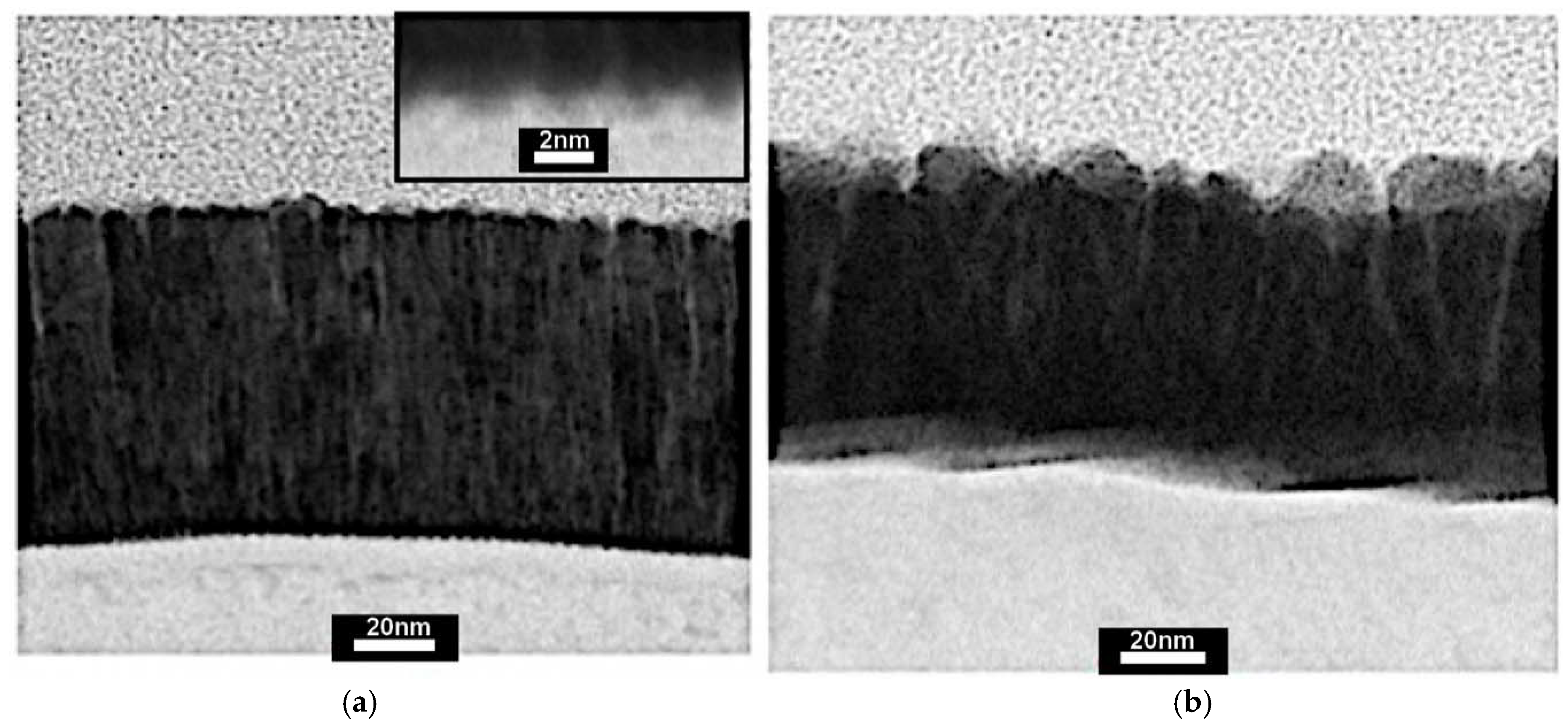
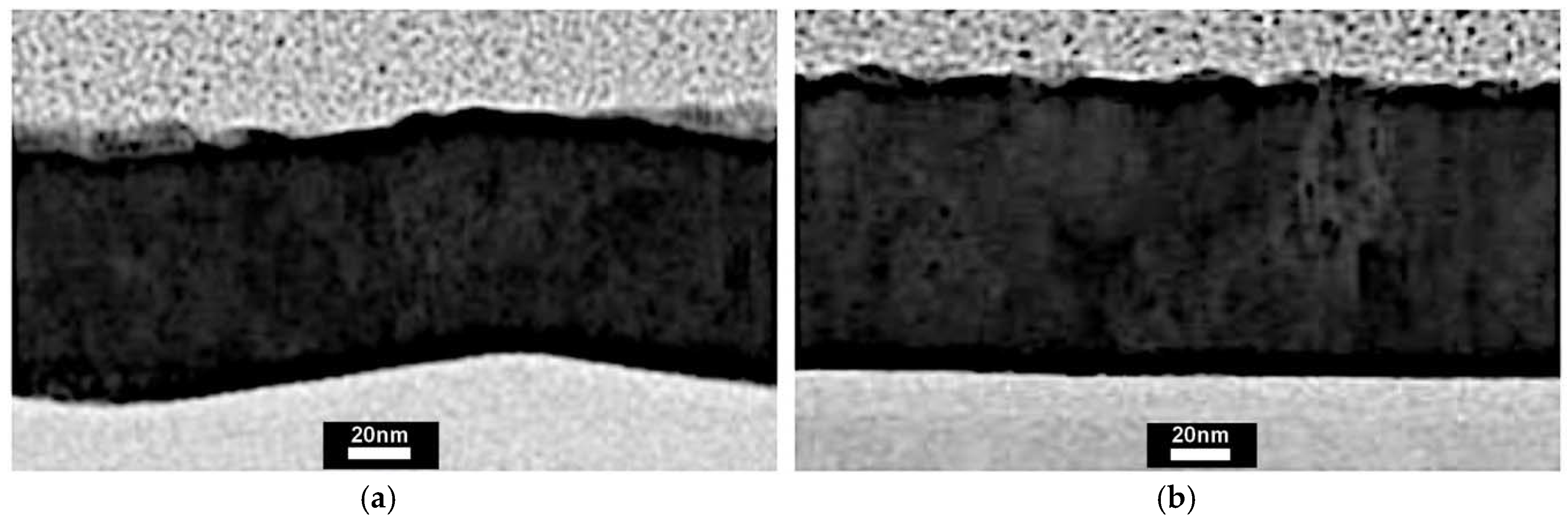
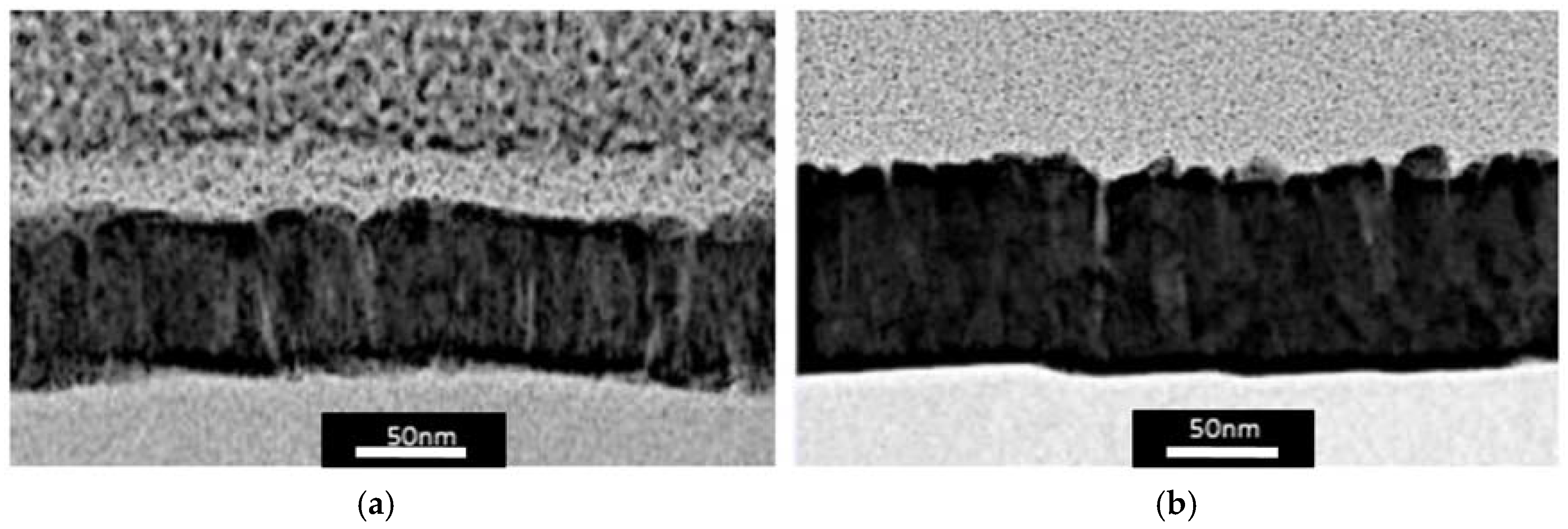
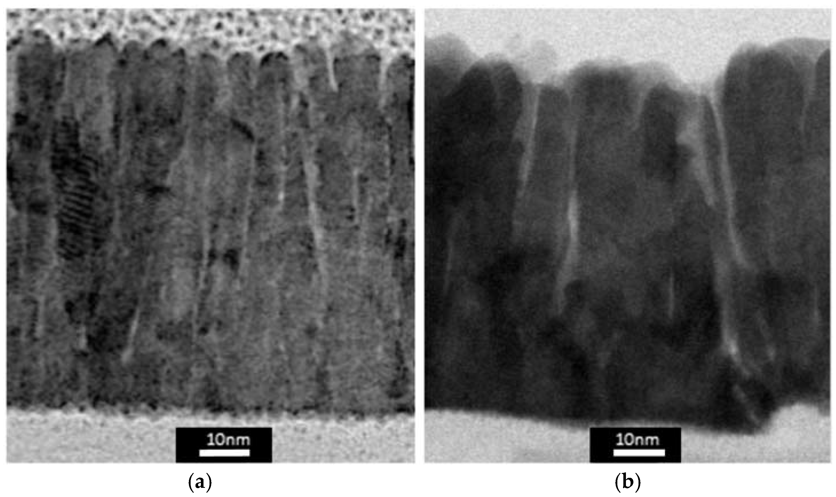
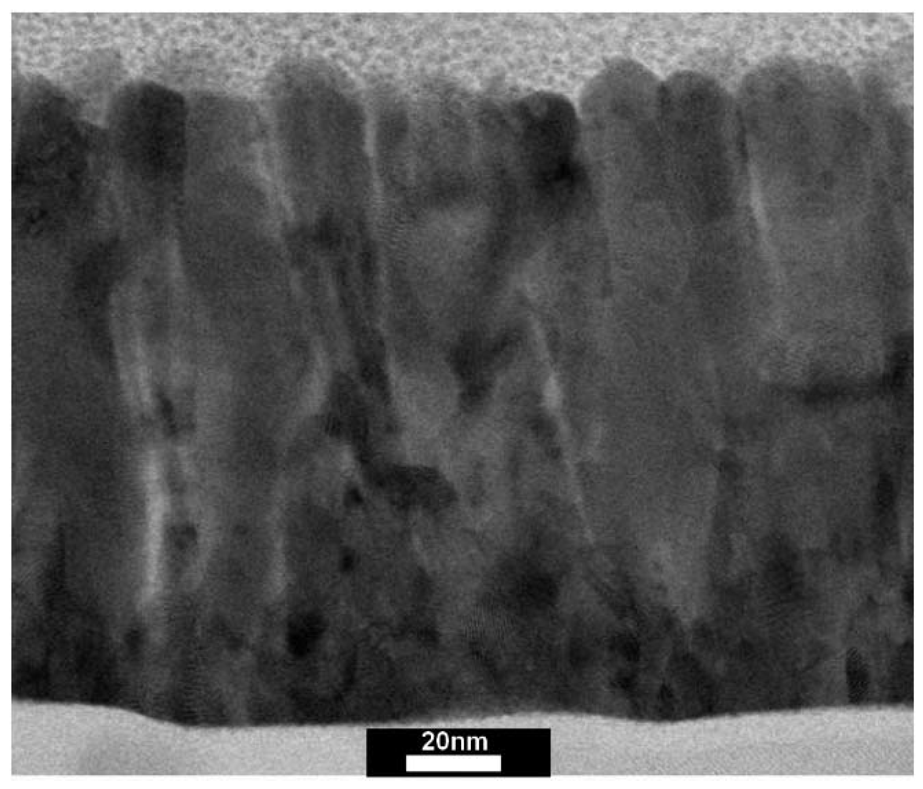
2.1. Microstructure of Electrocatalytic Layers

Preliminary investigations showed that pure graphite layers obtained by magnetron sputtering were not catalytically active. The catalytic activity of deposited Pt-C films and the specific surface area of the deposited platinum in such films increased with an increase of the platinum coverage area (volumetric content) of the sputtered Pt-C target. However, the catalytic activity of the films deposited using pure platinum target was lower than when 60 vol % (96 wt %) Pt-C target was used. Therefore, Pt-C target with 60% Pt coverage (surface) area and pure platinum target (for comparison) were used in the main investigations.
Pt and Pt-C films with 65–95 nm thicknesses were deposited using four sputtering regimes described below. Argon was used as working gas (pressure of 9.3 × 10⁻³ mbar) for all regimes. Sputter rate was in the range 7.0–7.5 mg/min. In order to determine the thickness dependence of electrocatalytic characteristics additional films with ~20 and 160 nm thicknesses were obtained in the regime of pulsed sputtering (100 kHz).
Titanium substrates (1 × 1 × 0.01 cm) cut from titanium foils of grade VT1-0 (technical titanium with high strength and anti-corrosive properties) were used in all experiments. Prior to deposition, the surface of the titanium substrates was pre-cleaned: heating to 250 °C in a vacuum of 2.6 × 10⁻⁴ mbar for 10 min followed by pulsed ionic cleaning for 15 min with a bias voltage of 600 V, 10 kHz (10% positive impulse) gas-argon, pressure of 1.3 × 10⁻² mbar.
Elemental composition analysis showed that platinum content in the films sputtered using Pt-C target was 95–97 wt %.
Nevertheless, at certain sputtering regimes the microstructure and catalytic properties of Pt-C films even with ~3–5 wt % carbon content differed significantly from those of Pt films (see below).
The microstructure of the samples deposited using stationary DC magnetron sputtering without bias voltage applied to the substrate is shown in Figure 1. The Pt-C film has a porous columnar structure. The roughness factor of its surface is 9.5 (according to electrochemical investigations data shown below). The Pt film has a more dense columnar structure with larger size of columns. The roughness factor is significantly lower than that of the Pt-C film and equals 5.4. It is worth stressing that the samples have a different morphology of the titanium substrate deposited film interface. In contrast to Pt films with a relatively smooth interface, Pt-C samples reveal an interface zone of about 2 nm with a fine structure. The elemental analysis data show the presence of Pt, Ti, C in this zone. According to the elemental analysis data, one can also suppose the formation of an intermediate Pt-Ti layer in the case of Pt film, however within the accuracy of measurements.
Microstructures of the samples produced by DC magnetron sputtering with pulsed bias voltage of −200 V (pulsed frequency 10 kHz) applied to the substrate are presented in Figure 2. Pt and Pt-C films have a similar dense with a smooth substrate-coating interface. Roughness factors are very low —1.86 for Pt-C film and 1.54 for the Pt one (close to the roughness factor for Pt foil).
Microstructures of the samples produced by pulsed magnetron sputtering (pulsed frequency 10 kHz) are shown in Figure 3. Pt and Pt-C films have a columnar structure with a rough surface and a low porosity. The film deposited by Pt target sputtering has a very dense layer of ~30 nm near the substrate surface. As the film thickness grows, the columns began to appear. Roughness factors of both films are similar: 5.7 for Pt-C and 6.1 for Pt. Substrate–film interfaces are smooth in both cases.
Microstructures of the samples produced by pulsed magnetron sputtering with frequency 100 kHz are shown in Figure 4. Roughness factors are 12.34 for Pt-C film and 10.76 for Pt film. Substrate–coating film interface zone of Pt-C sample has a fine structure. Pt-C film consists of narrow columns with dome nanotops (~5 nm in diameter) forming a well-developed surface. Columns of Pt films are significantly larger and have faceted tops forming a less developed surface. A denser Pt layer can be seen near the substrate. The structures of both samples are rather similar to those of samples produced using the DC regime without bias voltage applied to the substrate. However, the surfaces of the samples produced by pulsed sputtering are more developed especially for Pt-C film.
As mentioned above two additional samples with a thin (~20 nm) Pt layer and with a thick (~160 nm) Pt layer were produced by pulsed magnetron sputtering (frequency 100 kHz) to determine the dependence of the structural and catalytic properties on the film thickness. The 20 nm Pt film is very dense and has a nanocrystalline structure. The roughness factor is 1.55, which is close to the value for Pt foil (1.2–1.5).
The ~160 nm film structure is similar to the ~80 nm film structure shown in Figure 4b and has the densest part just above the titanium substrate. As the film grows the column formation begins (Figure 5). Roughness factor increases with the film thickness and is 15.6 for 160 nm (as stated above it is equal to 10.56 for 80 nm and 1.55 for 20 nm).
It should be noted that the maximum porosity is 30% (for the samples produced by Pt-C and Pt targets sputtering using pulsed magnetron sputtering regime with 100 kHz frequency). For the samples produced by Pt-C target magnetron sputtering in stationary DC regime the porosity is 20%. However, it is an integral porosity. (The densest layer is near the substrate and the porosity increases towards the film surface). The porosity is minimal for Pt-C and Pt samples produced by DC magnetron sputtering with pulsed bias voltage of −100 or −200 V applied to the substrate (less than 1%) and for Pt-C and Pt samples produced using pulsed magnetron sputtering regime with 10 kHz frequency (5%).

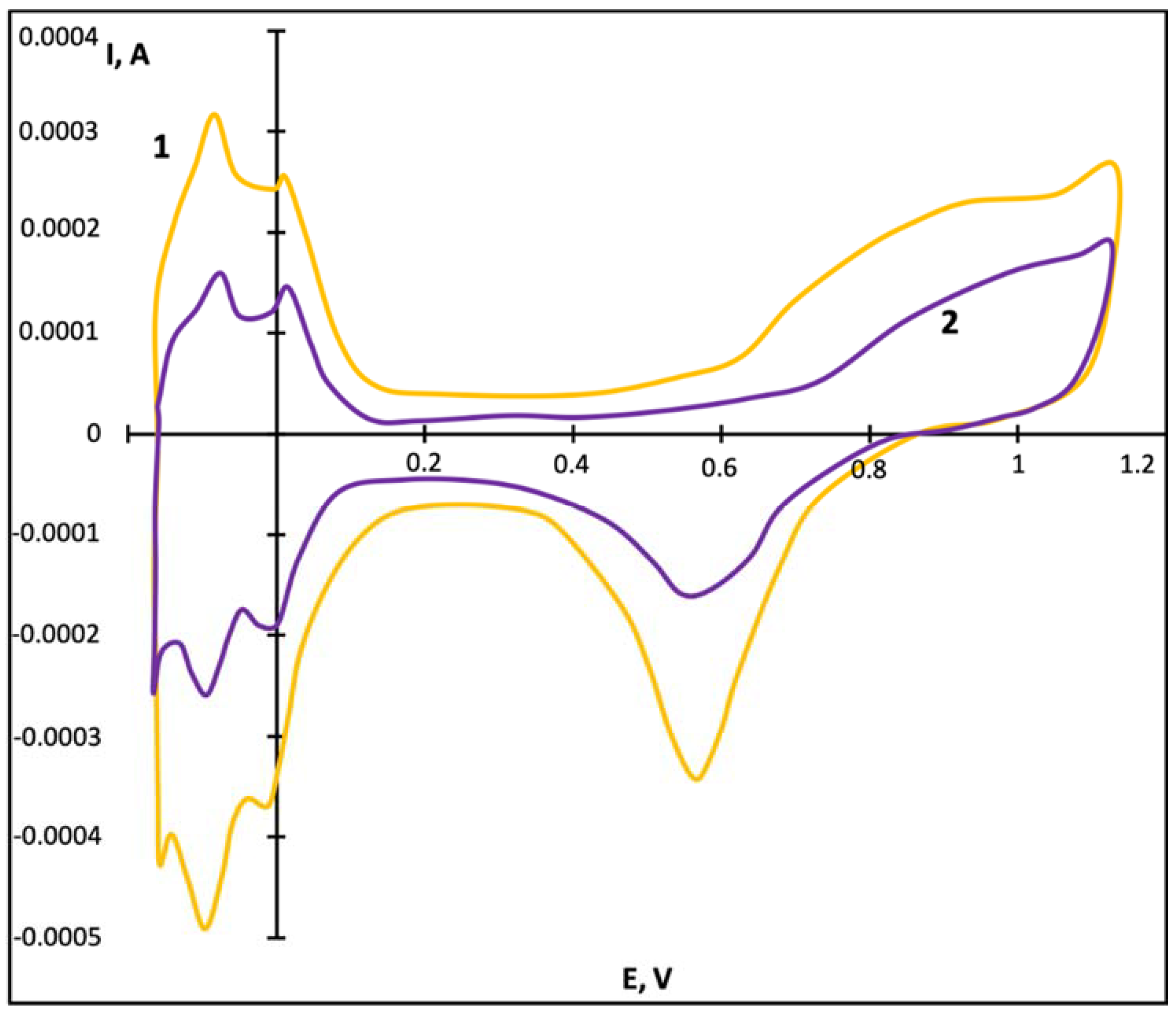
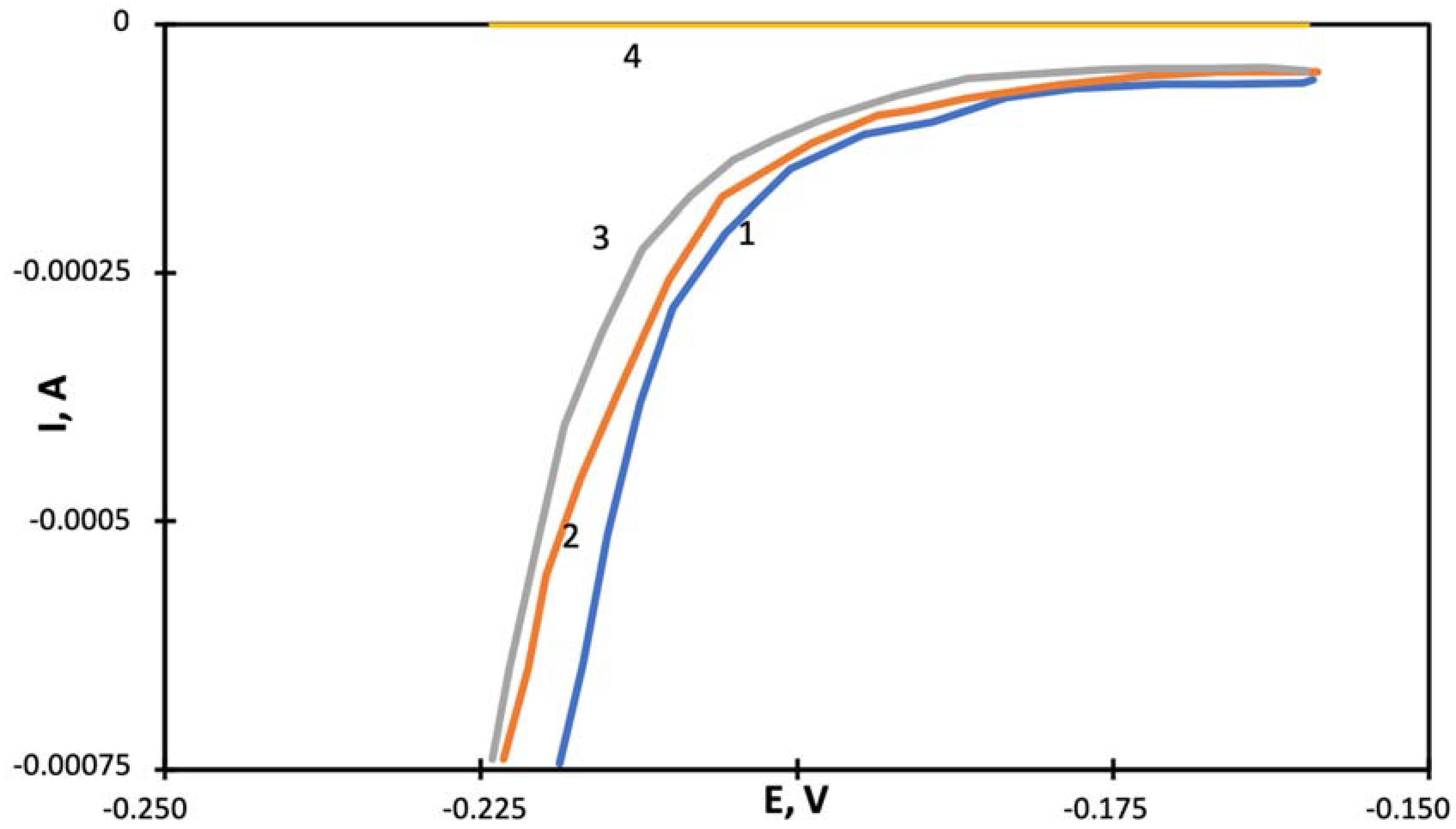
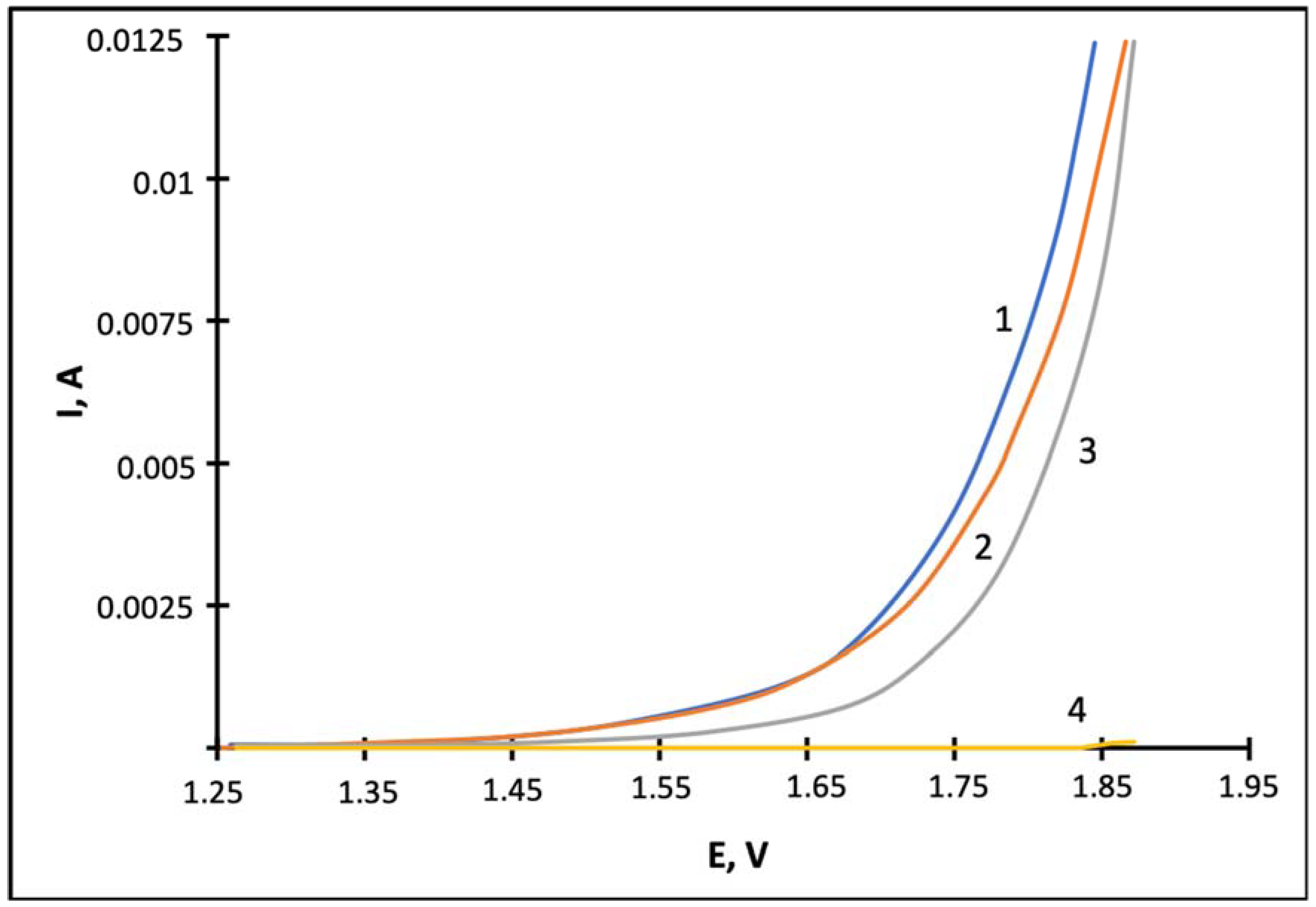
2.2. Electrocatalytic Properties of Pt/Ti Pt-C/Ti Electrodes

In Figure 6 the current-voltage (CV) curves for titanium electrodes with coatings obtained in the DC sputtering regime using Pt and Pt-C targets are shown (the microstructure of the films is demonstrated in Figure 1). At close values of the films thicknesses (87 nm and 75 nm), the currents of adsorption/desorption of hydrogen and oxygen differ by two times. At the same time, the curves in the hydrogen desorption region (from −0.2 to +0.2 V) differ in area size (in the amount of hydrogen desorbed). The shape of the peaks and their arrangement match each other, but the peak related to а strongly bound hydrogen (plane 100) at the Pt film surface has the same size as the peak corresponding to a weakly bound hydrogen. At the Pt-C film, the peak related to a weakly bound hydrogen (plane 111) is higher. The activity of Pt-C films (electrodes) is greater both in the hydrogen evolution (cathode potentials) and oxygen evolution (anode potentials) regions (Figure 7 and Figure 8). The currents in the “double layer” region in the potential range 0.2–0.4 V for cathode polarization differ very little for these electrodes (Figure 6). The roughness factor of the Pt electrode (film) is 5.2–5.4, which is almost four times higher than the roughness factor (1.2–1.5) of smooth platinum. The roughness factor for the Pt-C electrode is significantly higher—9.5.
The cathode currents (hydrogen evolution) and anode currents (oxygen evolution) for the Pt-C electrode are higher than the currents for the Pt electrode and the smooth platinum.
It is worth stressing that we did not observe any significant changes in CV-curves (values of currents, shape of peaks) over long time cycling (15 cycles) for these and other electrodes. Thus, even the surface of the Pt-C electrodes is rather electrochemically stable.
The electrochemical characteristics of the coatings obtained in the DC regime with pulsed bias voltage from −100 to −200 V applied to the Ti substrate are close to the electrochemical characteristics of smooth platinum. The roughness factors of Pt-C film and Pt film are 1.86 and 1.54, respectively. The microstructure of the films is shown in Figure 2. The films are dense and not porous. Their catalytic activity is small.
It can be assumed that similar regularities can also be observed when other metals are sputtered.
Pt and Pt-C films obtained by pulsed magnetron sputtering (PMS) with frequencies 10 kHz and 100 kHz were also tested. The microstructure of the samples is shown in Figure 3 and Figure 4. The films obtained at 100 kHz have the largest roughness factors (12.34 for Pt-C film and 10.76 for Pt film).
“Quasi-stationary” polarization curves in the potential range from 0.6 to −0.35 V at a rate of 0.1 mV/s are rather similar to all the electrodes obtained with a frequency of 10 and 100 kHz, though for Pt-C electrodes obtained at 100 kHz the currents were slightly higher. “Quasi-stationary” polarization curves in the potential range from 1.5 to +1.75 V are shown in Figure 9. Here the same Pt-C film (100 kHz) has the best characteristics among all the electrodes and the difference in anode currents is rather high.
“Quasi-stationary” polarization curves for all electrodes (films) in the cathode potential range from 0.60 to –0.35 V in a 1 M solution of sulfuric acid at a rate of 0.1 mV/s at 25 °C, differ less strongly, but the dependence of the catalytic activity of the electrodes on the deposition method is similar.
In preliminary research it was also shown that Pt-C films/catalysts deposited with frequency 100 kHz on commercial carbon gas diffusion layers for fuel cells (ELAT® LT 1400 W (FuelCellsEts, College Station, TX, USA), Sigracet® 10 BB (SGL Group, Wiesbaden, Germany)) have a higher specific surface (roughness factor) and activity in comparison with Pt films/catalysts deposited on the same materials (both in liquid solution and in a polymer electrolyte membrane fuel cell).

3. Discussion

The elemental composition analysis showed that the platinum content in the Pt-C deposited films (95–97 wt %) is practically the same as the platinum content in the target material (96 wt %), though the sputtering yield for Pt is higher than that for C [24]. It can be explained by the peculiarities of the composite target sputtering as in the process of platinum nanoparticles sputtering the carbon surface increases and the carbon sputtering efficiency also grows. Therefore, the target used in these experiments allows sufficiently reproducible composition of the deposited films to be obtained. It should be noted that in the investigations of other authors co-sputtering of two targets was used for Pt-C films deposition, which required more complicated equipment and more accurate control of the sputtering regimes [25,26,27].
Nevertheless, at certain sputtering regimes the microstructure and catalytic properties of Pt-C films with minor (~3–5 wt %) carbon content differed significantly from those of Pt films.
Data concerning film content and intermediate layers forming at the titanium-film interface show that the kinetic energy of the sputtered atoms is enough for their partial penetration into the titanium substrate. The results are in good agreement with results obtained in [21] which show that at Pt target sputtering, about 6% of the Pt atoms in the coating (Pt film) are replaced by Ti atoms (though the Pt coordination number remains the same). When Pt-C is used, the carbon atoms deposited on the substrate possibly limit the mobility of the deposited platinum species stabilizing Pt cluster growth. This is the reason for the narrow Pt columnar nanopillars structure origin. Dome nanotops (~5 nm in diameter) of these nanopillars form a well-developed film surface. Stabilization of platinum species by carbon atoms was confirmed by EXAFS (Extended X-Ray Absorption Fine Structure) investigations of the short range ordering structure of Pt clusters obtained by platinum and carbon co-deposition on the substrate in vacuum [27]. Columnar film structure was also produced by Pt and C targets co-sputtering using the DC magnetron regime [28].
A substantial difference in the structures and properties of the films obtained by DC sputtering without and with negative bias voltage applied to the titanium substrate is the denser structure of the latter ones. The structure and catalytic activity of the Pt and Pt-C films deposited by DC sputtering with negative bias voltage have minimal differences compared to those of films deposited using all other sputtering regimes. As was shown in [29] strong re-sputtering of deposited carbon atoms occurred at such a bias voltage. This explains the absence of microstructure dependence on target composition (in contrast to the case of DC sputtering without negative bias voltage). The mobility of the atoms on the surface of the titanium substrate increases leading to a porosity decrease. Roughness factors are 1.86 for Pt-C film and only 1.54 for Pt (close to the roughness factor for Pt foil, which equals 1.2–1.5). This is in a good agreement with data [29,30,31] that show that negative bias voltage application increases film density and improves hardness and adhesion. Catalytic activity of these films is low because their surface is not well developed (the roughness factor is low). However, they are certainly rather interesting as protective coatings for catalytic systems working in aggressive medium, for example for the anode current collector of PEM (Proton Exchange Membrane or Polymer Electrolyte Membrane) electrolyzers and cathode gas diffusion layers of fuel cells.
The regimes of pulse sputtering in comparison with DC sputtering increase the discharge current density and ionization degree of the sputtered material [32]. The pulsed regime of sputtering reduces substrate thermal loading. A bipolar power source allows reverse pulse polarity thus eliminating arching problems. Moreover, it gives a rise to some additional effects which influence the deposited film properties. These effects depend on the frequency and duty cycle [33,34].
Properties of Pt and Pt-C films deposited by pulsed sputtering strongly depend on the process frequency. Parameters (roughness factors and porosity) of the films obtained by pulse sputtering with 10 kHz frequency have intermediate values with respect to parameters of the films obtained by DC sputtering without and with negative bias voltage applied to the titanium substrate. The same parameters of the films obtained by pulse sputtering with 100 kHz are significantly higher. At the same Pt content the Pt surface area (roughness factors) for 100 kHz is twice that for 10 kHz and the porosity is six times higher. One can suppose that current density increase at 100 kHz along with reduced pulses duration inhibits large globule growth and leads to highly homogenous fine grain/pillar structures with a developed surface area and an increased porosity.
Probably due to these effects, the films obtained at 100 kHz have maximum porosity (~30%) and roughness factors. It should be noted that carbon addition has a strong influence on the film properties. When Pt-C is used the carbon atoms deposited on the substrate stabilize Pt cluster growth therefore a narrow Pt columnar nanopillar structure with a well-developed surface is formed. Columns of films produced by Pt target sputtering are significantly larger and form a less developed surface.
Certainly, the degree of surface development (the roughness factor) in many respects determines the catalytic activity of the produced films. However, there is no linear dependence. For example, the difference in anode current values for the films obtained by DC sputtering and by pulsed sputtering with 100 kHz is significantly less than can be expected from the comparison of roughness factors and porosity values (20% and 30% correspondingly). Undoubtedly, at rather high anode currents and oxygen evolution the pore diameters and structure should play a vital part as the evolving gas can block a part of the pores from participation in the process. Probably differences in the film catalytic activity would be more strongly dependent on porosity values and roughness factors for the catalytic processes in a gas phase. It is also worth to stressing that the stability of currents over long time potential cycling shows that there is not any selective carbon dissolution at anode potentials and increase of platinum surface in platinum-carbon films. One can suppose that the reason for this is a strong platinum–carbon interaction in the platinum carbon films. In such a case a certain decrease in specific platinum catalytic activity due to platinum interaction with carbon also cannot be excluded. But even with a possible decrease of the specific activity the efficiency of the platinum-carbon films/catalysts is greater due to their structure even with a decreased platinum content in the films.
The magnetron sputtering technique has already demonstrated some perspectives for polymer electrolyte electrolyzers and fuel cells [7,21,22,23,35]. The further development of the methods described above could be very useful for such systems.

4. Materials and Methods

4.1. Method of Magnetron Sputtering

The catalytic layers were obtained by magnetron sputtering using the laboratory unit MIR-1 (Installation of own production) [7,23] with a bipolar power source APEL-SB-5BP-1300 (Applied Electronics, Tomsk, Russia), which can be used both for supplying the bias voltage to the substrate and as a power source for magnetron sputtering systems. The operating parameters of the installation: magnetron discharge current up to 5 A, magnetron discharge voltage 350–500 V. Technical characteristics APEL-SB-5BP-1300: power 5 kW, adjustable output voltage range 65–1300 V, adjustable output negative current range 0.1–4.0 A, positive current amplitude 2 A, pulse frequency control range 1–100 kHz (1 kHz step), positive pulse adjustment range 3–50 μs.
Argon was used as working gas at a pressure of 9.3 × 10⁻³ mbar. For comparative studies the electrocatalytic layers were produced by DC sputtering without applying a bias voltage to the substrate and when applying pulsed bias voltage of −100 to −200 V (the magnetron current 0.05 A, the magnetron voltage 410 V, frequency of 10 kHz the duration of the negative pulse is 90 μs, the positive pulse—10 μs), and by pulsed magnetron sputtering with frequency of 10 kHz (90 μs the negative pulse, 10 μs the positive pulse, the magnetron current 0.06–0.09 A, the magnetron voltage 328–400 V) and with a frequency of 100 kHz (the negative pulse duration of 7 μs, the positive pulse—3 μs, the magnetron current 0.10 A, the magnetron voltage 410 V).
In all cases, prior to deposition, the surface of the titanium substrate was pre-cleaned: heating to 250 °C in a vacuum of 2.6 × 10⁻⁴ mbar for 10 min followed by pulsed ionic cleaning for 15 min with a bias voltage of 600 V, 10 kHz (10% positive impulse) gas-argon, pressure—1.3 × 10⁻² mbar.

4.2. Materials

For the deposition of catalytic layers, a platinum target and a platinum target with graphite additives (All the chemicals were purchased from Russian trade mark) (target diameter 42 mm, thickness 1 mm) were used. The platinum target with graphite additives was obtained by pressing platinum black (particle size of 10–50 nm) with a powder of reactor graphite (particle size of 0.1–10 μm). The concentration of platinum in the composite targets was 10, 30, and 60 vol % (which is equal to the proportion of the platinum surface in the composite target). We used substrates 1 × 1 × 0.01 cm, cut from titanium foils of grade VT1-0 (Russian trade mark) (technical titanium with high strength and anti-corrosive properties).

4.3. Microstructure and Elemental Composition of Coating

To study the microstructure of titanium samples with platinum coatings, an electron microscope Titan 80–300 S/TEM (Scanning Transmission Electron Microscopy) (FEI, Hillsboro, OR, USA) was used with a spherical aberration corrector in a light and dark field. Elemental composition was determined by energy dispersive X-ray spectroscopy using a microanalysis attachment (EDAX Inc., Mahwah, NJ, USA). The carbon content in the target was also estimated by the weighting method—by weight of films of known thickness.
The porosity (p) of the sputtered films was determined by a gravimetric method according to the formula
p = (1 − ρ12) × 100%,
where ρ2 is the density of the film material kg/m3, and
ρ1 = m/V
where m is the weight of the porous film, kg, V is the porous film volume, m3).

4.4. Electrochemical Measurements

Electrochemical studies to determine the specific surface area of platinum and the catalytic activity of the deposited layers in hydrogen and oxygen evolution reactions were carried out on a Solartron 1285 potentiostat (Solatron Metrology, West Susex, UK) in a three-electrode cell with Ag/AgCl (saturated KCl solution) (Saturated KCl solution was prepared from KCl produced by Russian company RENOIL, Russia), a reference electrode. All potential values are given relative to this electrode. The electrolyte was a solution of 1 M sulfuric acid, prepared in bidistilled water (Klinlab, Klin, Russia), counter electrode of platinum wire, and a working electrode of titanium foil 1 × 1 cm2 with platinum deposited by ion-magnetron sputtering welded to a thin titanium wire. The maintenance of the thermal regime of the cell (25 °C) was carried out by a thermostat. To eliminate the effect of dissolved oxygen in the electrolyte, as well as to stir the electrolyte solution, the cell was purged with the inert gas argon. To obtain a stable potentiodynamic curve, the electrode was pre-cycled (6 times) in the range from −0.17 V to 1.2 V with a sweep rate of 20 mV/s. This mode was used as a standard pre-treatment for all the electrodes described below.
The roughness factor for Pt (the ratio of the real surface of platinum to the visible geometric surface) and the catalytic activity of the platinum coatings obtained by sputtering Pt and Pt-C targets was evaluated by an electrochemical method using potentiodynamic and “quasi-stationary” (scan rate 0.1 mV/s) curves.

5. Conclusions

In this study platinum and platinum-carbon catalytic layers were obtained on titanium substrates by magnetron sputtering. Morphological, structural, and electrocatalytic properties of deposited films were investigated for determination of the optimal DC and pulse magnetron sputtering regimes. The analysis of the experimental data shows that the changes in sputtering regimes enable the structure and electrocatalytic properties of the deposited films to vary significantly. A considerable difference in the structures and properties of the films obtained by DC sputtering without and with negative bias voltage applied to the titanium substrate is a denser structure of the latter. The catalytic activity of dense films is low because their surface is not well developed, however, they can be used as protective coatings for catalytic systems working in an aggressive medium. The properties of Pt and Pt-C films deposited by pulsed sputtering strongly depend on the process frequency. Roughness factors and porosity of the films obtained by pulse sputtering with 10 kHz frequency have intermediate values with respect to parameters of the films obtained by DC sputtering without and with negative bias voltage applied to the titanium substrate. Roughness factors for the films obtained by pulse sputtering with 100 kHz are twice that for 10 kHz and the porosity is six times higher.
Carbon (graphite) additive to the platinum target (and therefore to the deposited layer) was chosen because of its rather high chemical resistance in an acidic medium under the conditions of operation of the fuel cells cathodes and anodes, and the cathodes of electrolysis cells. Moreover, if carbon carriers are used, sputtered carbon species would not add foreign impurities. Experimental results show that carbon has a strong influence on the film structure and allows an increase in the films porosity, roughness factor, and catalytic activity to be obtained. The most pronounced effect is observed for the films sputtered using a pulsed regime with 100 kHz frequency. When Pt-C target is used a narrow Pt columnar nanopillar structure is formed because the carbon atoms deposited on the substrate limit the mobility of the deposited platinum species stabilizing the Pt cluster growth. Dome nanotops (~5 nm in diameter) of these nanopillars form a well-developed film surface. Columns of Pt films are significantly larger and form a less developed surface.
The electrochemical measurements, which were used for estimation of the films specific surface and their electrochemical/catalytic activity, demonstrated some advantages of Pt-C films.

Author Contributions

Conceptualization, V.N.F.; investigation, O.K.A., A.I.M., E.K.L., and B.L.S.; data analysis V.I.P. and M.Yu.P.; supervision, V.N.F.; writing and revision of the current literature, O.K.A. and E.K.L.; writing—review, correction, and editing, S.A.G.

Funding

This research was conducted with financial support of the Ministry of Education and Science of the Russian Federation (unique project identifier RFMEFI60417X0171) in NRC “Kurchatov Institute”.

Conflicts of Interest

The authors declare no conflict of interest.

References

  1. Wang, Y.-J.; Zhao, N.; Fang, B.; Li, H.; Bi, X.T.; Wang, H. Carbon-Supported Pt-based Alloy Electrocatalysts for the Oxygen Reduction Reaction in Polymer Electrolyte Membrane Fuel Cells: Particle Size, Shape, and Composition Manipulation and their Impact to Activity. Chem. Rev. 2015, 115, 3433–3467. [Google Scholar] [CrossRef] [PubMed]
  2. Sui, S.; Wang, X.; Zhou, X.; Su, Y.; Riffat, S.; Liu, C. A Comprehensive Review of Pt Electrocatalysts for the Oxygen Reduction Reaction: Nanostructure, Activity, Mechanism and Carbon Support in PEM fuel cells. J. Mater. Chem. A 2017, 5, 1808–1825. [Google Scholar] [CrossRef]
  3. Sapountzi, F.M.; Gracia, J.M.; Weststrate, C.J.; Fredriksson, H.O.A.; Niemantsverdriet, J.W. Electrocatalysts for the Generation of Hydrogen, Oxygen and Synthesis Gas. Prog. Energy Combust. Sci. 2017, 58, 1–35. [Google Scholar] [CrossRef]
  4. Yashtulov, N.A.; Revina, A.A.; Lebedeva, M.V.; Flid, V.R. Catalytic activity of polymer-palladium metal nanocomposites in oxygen reduction and hydrogen oxidation reactions. Kinet. Catal. 2013, 54, 322–325. [Google Scholar] [CrossRef]
  5. Smirnova, N.V.; Kuriganova, A.B.; Leont’eva, D.V.; Leont’ev, I.N.; Mikheikin, A.S. Structural and electrocatalytic properties of Pt/C and Pt-Ni/C catalysts prepared by electrochemical dispersion. Kinet. Catal. 2013, 54, 255–262. [Google Scholar] [CrossRef]
  6. Lebedeva, M.V.; Yashtulov, N.A.; Flid, V.R. Catalysts with platinum–palladium nanoparticles on polymer matrix supports. Kinet. Catal. 2016, 57, 847–852. [Google Scholar] [CrossRef]
  7. Alexeeva, O.K.; Fateev, V.N. Application of the Magnetron Sputtering for Nanostructured Electrocatalysts Synthesis. Int. J. Hydrog. Energy 2016, 41, 3373–3386. [Google Scholar] [CrossRef]
  8. Alexeeva, O.K.; Gavrilkin, A.A.; Legasov, V.A.; Romanovskiy, B.V.; Rusanov, V.D.; Safonov, M.S.; Sumarokov, V.N.; Chistov, A.G.; Chumak, P.S. Characteristics of supported ribbon catalyst with an active layer of Raney-nickel. Kinet. Catal. 1987, 28, 216–219. [Google Scholar]
  9. Kuleshov, V.N.; Kuleshov, N.V.; Grigoriev, S.A.; Udris, E.Y.; Millet, P.; Grigoriev, A.S. Development and characterization of new nickel coatings for application in alkaline water electrolysis. Int. J. Hydrog. Energy 2016, 41, 36–45. [Google Scholar] [CrossRef]
  10. Alexeeva, О.K.; Iltchenko, N.L.; Panteleimonova, A.A.; Novikov, A.A.; Sumarokov, V.N. Modified hydrogen sulfide adsorbents-catalysts. Int. J. Hydrog. Energy 1994, 19, 693–696. [Google Scholar] [CrossRef]
  11. Alexeeva, O.K.; Klebanov, Y.D.; Safonova, A.M.; Sidorov, G.L.; Sumarokov, V.N.; Vinogradova, E.A. Preparation of adsorption-catalytic and protective coatings on carbon fibers used for hydrogen purification. Int. J. Hydrog. Energy 1999, 24, 241–246. [Google Scholar] [CrossRef]
  12. Alekseeva, O.K.; Amirkhanov, D.M.; Bryazkalo, A.M.; Kotenko, A.A.; Potapkin, B.V.; Fateev, V.N.; Chelyak, M.M. Composite functional materials with metal coatings (alloys) Pt_ groups or their substitutes for the problems of hydrogen energy. Dragotsennye metally. Dragotsennye Kamni 2006, 12, 139–150. (In Russian) [Google Scholar]
  13. Ralph, T.R.; Hogarth, M.P. Catalysis for low temperature fuel cells. Platin. Met. Rev. 2002, 46, 3–14. [Google Scholar]
  14. Wang, Y.; Leung Dennis, Y.C.; Xuan, J.; Wang, H. A review on unitized regenerative fuel cell technologies, part-A: Unitized regenerative proton exchange membrane fuel cells. Renew. Sustain. Energy Rev. 2016, 65, 961–977. [Google Scholar] [CrossRef]
  15. Xu, W.; Jyoti, T.; Suddhasatwa, B.; Keith, S. Nano-crystalline RuxSn1xO2 powder catalysts for oxygen evolution reaction in proton exchange membrane water electrolysers. Int. J. Hydrog. Energy 2011, 36, 14796–14804. [Google Scholar] [CrossRef]
  16. Zhang, S.; Shao, Y.Y.; Yin, G.P.; Lin, Y.H. Carbon nanotubes decorated with Pt nanoparticles via electrostatic selfassembly: A highly active oxygen reduction electrocatalyst. J. Mater. Chem. 2010, 20, 2826–2830. [Google Scholar] [CrossRef]
  17. Fedotov, A.A.; Grigoriev, S.A.; Millet, P.; Fateev, V.N. Plasma-assisted Pt and Pt-Pd nano-particles deposition on carbon carriers for application in PEM electrochemical cells. Int. J. Hydrog. Energy 2013, 38, 8568–8574. [Google Scholar] [CrossRef]
  18. Fedotov, A.A.; Grigoriev, S.A.; Lyutikova, E.K.; Millet, P.; Fateev, V.N. Characterization of carbon-supported platinum nano-particles synthesized using magnetron sputtering for application in PEM electrochemical systems. Int. J. Hydrog. Energy 2013, 38, 426–430. [Google Scholar] [CrossRef]
  19. Fedotov, A.A.; Grigor’ev, S.A.; Glukhov, A.S.; Dzhus, K.A.; Fateev, V.N. Synthesis of nanostructured electrocatalysts based on magnetron ion sputtering. Kinet. Catal. 2012, 53, 753–758. [Google Scholar] [CrossRef]
  20. Grigor’ev, S.A.; Pushkarev, A.S.; Kalinichenko, V.N.; Pushkareva, I.V.; Presnyakov, M.Y.; Fateev, V.N. Electrocatalytic layers based on reduced graphene oxide for fabrication of low-temperature fuel cells. Kinet. Catal. 2015, 56, 689–693. [Google Scholar] [CrossRef]
  21. Fateev, V.N.; Alekseeva, O.K.; Lutikova, E.K.; Porembskiy, V.I.; Nikitin, S.M.; Mikhalev, A.I. New physical technologies for catalyst synthesis and anticorrosion protection. Int. J. Hydrog. Energy 2016, 41, 10515–10521. [Google Scholar] [CrossRef]
  22. Alekseeva, O.K.; Lutikova, E.K.; Markelov, V.V.; Porembsky, V.I.; Fateev, V.N. Stationary and Pulsed Magnetron Sputtering Technologies for Protective/Catalyst Layer Production for PEM Systems. Int. J. Electrochem. Sci. 2018, 13, 797–811. [Google Scholar] [CrossRef]
  23. Fateev, V.N.; Alekseeva, O.K.; Porembskiy, V.I.; Mikhalev, A.I.; Nikitin, S.M. Corrosion resistant electrodes/current collectors for anodes of electrolysis cells with solid polymer electrolyte. Altern. Energy Ecol. 2017, 25–27, 88–99. [Google Scholar] [CrossRef]
  24. Sputtering Yield Rates. Available online: http://www.semicore.com/reference/sputtering-yields-reference (accessed on 16 December 2018).
  25. Umeda, M.; Nagai, K.; Shibamine, M.; Inoue, M. Methanol oxidation enhanced by the presence of O2 at novel Pt–C co-sputtered electrode. Phys. Chem. Chem. Phys. 2010, 12, 7041–7049. [Google Scholar] [CrossRef] [PubMed]
  26. Mougenot, M.; Andreazza, P.; Andreazza-Vignolle, C.; Escalier, R.; Sauvage, T.; Lyon, O.; Brault, P. Cluster organization in co-sputtered carbon-platinum films as revealed by grazing incidence X-ray scattering. J. Nanopart. Res. 2012, 14, 672. [Google Scholar] [CrossRef]
  27. Ovsyannikov, F.M.; Shuvaev, A.T.; Lyubeznova, T.A.; Aleshin, V.A.; Gubina, S.O. EXAFS-study of the short-range structure of Pt metalloclusters obtained by the joint deposition of platinum and carbon on a substrate in a vacuum. Phys. Solid State 1993, 35, 3128–3134. (In Russian) [Google Scholar]
  28. Nechitalov, A.A.; Zvonareva, T.K.; Remenyuk, A.D.; Tolmachev, V.A.; Goryachev, D.N.; El’tsina, O.S.; Belyakov, L.V.; Sreseli, O.M. Catalytic properties of composite amorphous carbon-platinum layers in fuel cells. Semiconductors 2008, 42, 1249–1254. [Google Scholar] [CrossRef]
  29. Dai, H.Y.; Wang, Y.Q.; Cheng, X.R.; Zhan, C.Y.; Huang, N.K. Characterization and properties of amorphous carbon coatings prepared by middle frequency pulsed unbalanced magnetron sputtering at different substrate bias. Appl. Surf. Sci. 2012, 258, 5462–5466. [Google Scholar] [CrossRef]
  30. Chun, S.Y. Bias voltage effect on the properties of TiN films by reactive magnetron sputtering. J. Korean Phys. Soc. 2010, 56, 1134. [Google Scholar] [CrossRef]
  31. Dzhumaliev, A.S.; Nikulin, Y.V.; Filimonov, Y.A. Bias voltage influence on structure, morphology and magnetic properties of nickel films deposited by DC magnetron sputtering. Nanoinzheneriya 2013, 2, 24–29. (In Russian) [Google Scholar]
  32. Sharma, S.; Gahan, D.; Scullin, P.; Doyle, J.; Lennon, J.; Vijayaraghavan, R.K.; Daniels, S.; Hopkins, M.B. Measurement of deposition rate and ion energy distribution in a pulsed dc magnetron sputtering system using a retarding field analyzer with embedded quartz crystal microbalance. Rev. Sci. Instr. 2016, 87, 043511. [Google Scholar] [CrossRef] [PubMed]
  33. Bradley, J.W.; Welzel, T. Physics and phenomena in pulsed magnetrons: An overview. J. Phys. D Appl. Phys. 2009, 42, 093001. [Google Scholar] [CrossRef]
  34. Kelly, P.J.; Bradley, J.W. Pulsed magnetron sputtering—Process overview and applications. J. Optoelectron. Adv. Mater. 2009, 11, 1101–1107. [Google Scholar]
  35. Khan, A.; Nath, B.K.; Chutia, J. Nanopillar structured Platinum with enhanced catalytic utilization for electrochemical reactions in PEMFC. Electrochim. Acta 2014, 146, 171–177. [Google Scholar] [CrossRef]
Figure 1. STEM image of the samples produced by Pt-C and Pt targets sputtering using DC regime without bias voltage applied to the substrate. (a) Pt-C film deposited on Ti substrate. Scale bar is 20 nm. (The inset shows an enlarged image of the interface zone. Scale bar is 2 nm). (b) Pt film deposited on Ti substrate. Scale bar is 20 nm.
Catalysts 08 00665 g001
Figure 2. STEM image of the samples produced by Pt–C and Pt targets sputtering using DC regime with pulsed bias voltage of −200 V (pulsed frequency 10 kHz) applied to the substrate. (a) Pt-C film deposited on Ti substrate. (b) Pt film deposited on Ti substrate. Scale bar 20 nm.
Catalysts 08 00665 g002
Figure 3. STEM image of the samples produced by Pt-C and Pt targets sputtering using pulsed magnetron sputtering regime (frequency 10 kHz). (a) Pt-C film deposited on Ti substrate. (b) Pt film deposited on Ti substrate. Scale bar 50 nm.
Catalysts 08 00665 g003
Figure 4. STEM image of the samples produced by Pt-C and Pt targets sputtering using pulsed magnetron sputtering regime (frequency 100 kHz). (a) Pt-C film deposited on Ti substrate. (b) Pt film deposited on Ti substrate. Scale bar 10 nm.
Catalysts 08 00665 g004
Figure 5. STEM image of the sample with 160 nm Pt film produced by Pt target sputtering using pulsed regime (frequency 100 kHz). Scale bar 20 nm.
Catalysts 08 00665 g005
Figure 6. Current-voltage (CV) curves for smooth titanium electrodes with coatings obtained in the DC sputtering regime recorded in 1 M solution of sulfuric acid at temperature 25 °C (scan rate 20 mV/s). Curve 1—Pt-C film; curve 2—Pt film.
Catalysts 08 00665 g006
Figure 7. Polarization curves for smooth titanium electrodes with platinum coating obtained in the DC sputtering regime recorded in an aqueous solution of 1 M of sulfuric acid in the potential region from −0.25 V to −0.15 V at temperature of 25 °C (scan rate 0.1 mV/s). Curve 1—Pt-C target was sputtered; curve 2—Pt target was sputtered. Curves 3 for platinum foil and curve 4 for smooth titanium are given for comparison.
Catalysts 08 00665 g007
Figure 8. Polarization curves for smooth titanium electrodes with coatings obtained in the DC sputtering mode recorded in an aqueous solution of 1 M of sulfuric acid at temperature 25 °C (scan rate 0.1 mV/s). Curve 1—Pt-C target was sputtered; curve 2—Pt target was sputtered. Curve 3—Pt foil and curve 4—smooth titanium are given for comparison.
Catalysts 08 00665 g008
Figure 9. Polarization curves for smooth titanium electrodes with different films recorded in aqueous solution of 1 M of sulfuric acid in the potential region from 1.50 V to +1.75 V at temperature of 25 °C (scan rate 0.1 mV/s). Curve 1—Pt-C film obtained in the regime of PMS 10 kHz. Curve 2—Pt-C film obtained in the regime of PMS 100 kHz. Curve 3—Pt-C film obtained in the DC regime. Curve 4—Pt film obtained in the regime of PMS 10 kHz. Curve 5—Pt film obtained in the regime of PMS 100 kHz. Curve 6—Pt film obtained in the DC regime. Curve 7—Pt foil.
Catalysts 08 00665 g009

