Article

Nitrogen Self-Doped Metal Free Catalysts Derived from Chitin via One Step Method for Efficient Electrocatalytic CO2 Reduction to CO

1
School of Chemistry and Chemical Engineering, Anhui University of Technology, Ma’anshan 243002, China
2
Biochemical Engineering Research Center, Anhui University of Technology, Ma’anshan 243002, China
*
Author to whom correspondence should be addressed.
Catalysts 2023, 13(5), 904; https://doi.org/10.3390/catal13050904
Submission received: 11 April 2023 / Revised: 1 May 2023 / Accepted: 14 May 2023 / Published: 18 May 2023
(This article belongs to the Section Electrocatalysis)

Abstract

:
In this study, a facile one-step method via pyrolysis was used to prepare nitrogen self-doped metal free catalysts derived from inexpensive biomass-chitin for an electrochemical CO2 reduction reaction (CO2RR). The microstructure, surface area, defect and N type in the catalysts were analyzed by BET, Raman, XPS, SEM and TEM. The sustainable chitin-based electrocatalyst prepared under optimized conditions has a surface area of 1972 m2/g and can convert CO2 into CO with FECO of ~90% at a potential of −0.59 V (vs. RHE). This good CO2RR performance results from plentiful active sites due to a high surface area, rich ultra-micropores that are beneficial to CO2 adsorption, abundant mesopores for CO2 transport improvement, a high content of pyridinic and graphitic nitrogen that is favorable for a CO2 reduction reaction and a low interfacial charge transfer resistance leading to a rapid electron transfer rate from the catalyst to CO2. This study shows the feasibility of N self-doped biomass-derived catalysts for CO2RR with the potential for large-scale industrial applications.

1. Introduction

In recent years, the continuously rising level of CO2 in the atmosphere caused by the excessive use of fossil fuels has become the primary drive of environmental problems, leading to serious impacts on sustainable development [1]. To reduce CO2 emission, technology for efficient CO2 capture and conversion is highly demanded. Direct conversion of CO2 to valuable products has become of considerable interest [2,3]. Among various approaches, an electrochemical CO2 reduction reaction (CO2RR) coupling with a renewable energy source [4] is a promising method for achieving a carbon-neutral energy cycle and conversion to hydrocarbons at mild operation conditions [5,6,7].
Due to the thermodynamic stability of CO2, high overpotentials are always required to convert CO2 into the desired chemicals and fuels [8,9,10,11,12]. Among the various reduction processes, the reduction of CO2 to CO, which has a relatively high selectivity and a facile separation procedure, is one of the most promising practices. Over the past decades, commonly used electrocatalysts for CO evolution are metal-based catalysts such as noble metal-based catalysts (Au, Ag) [13,14] and transition metal-based catalysts (Ni, Fe) [15,16]. Although metal-based catalysts for CO2RR have several weaknesses, such as high cost, poor stability and non-renewability [17,18], metal-free-based catalysts are much more attractive for electrochemical CO2 reduction.
Due to intrinsic advantages such as low cost, natural abundance and excellent thermal/chemical stability, metal free-based electrocatalysts provide a promising platform for converting CO2 to CO [19,20,21]. Carbon-based electrocatalysts, a type of metal free catalyst, have emerged as alternative catalysts to be used for CO2RR [22]. Massive efforts have been made to construct carbon-based metal-free catalysts by several strategies, such as atomic doping and defecting of carbon lattice [23], to improve catalytic activity of pristine graphene for CO2RR [24]. All these approaches create active sites in metal-free-based catalysts, leading to changes in electronic structures and modulating the adsorption energy and reaction activation energy of intermediates for CO2 reduction [25,26]. An abundance of pyridinic-N was demonstrated to be an active site for high FECO of 92% and 84% on the wrinkle-free and wrinkled carbon nanosheets [27,28] and 85 and 89% on the graphene foam and graphene nano-ribbon network [29,30]. Defect-rich carbon catalysts prepared by N removal are around two-fold greater than edge-rich graphene [31], with FECO of around 80% at −0.6 V [32]. Hence, the combination of atomic doping with the defect engineering is a favorable strategy for enhancing CO’s selective performance in CO2RR.
Biomass is a renewable precursor with great potential for synthesizing carbon-based electrocatalysts for diverse electrocatalytic reactions [33]. However, the direct conversion of biomass into a highly active electrocatalysts for CO2RR is reported only in limited studies. Wood- and wheat-derived carbons with N-doping assist the conversion of CO2 into CO [34,35]. Hao et al. developed a cedar biomass-derived N-doped graphitized carbon electrocatalyst via a two-step preparation, achieving an FECO of 91% at −0.56 V (vs. RHE) and a partial current density (PCD) to CO at about 3.7 mA cm−2 [36]. A defect-rich carbon electrocatalyst derived from the nitrogen-rich silk cocoon prepared using two-step carbonization catalyzed CO2 reduction to CO with an FECO of ~89% at −1.09 V (vs. RHE) but PCD of CO at around 1 mA cm−2 [37].
N abundant biomass as a potential carbon source is an ideal source for preparing carbon-based electrocatalysts. Due to the efficiency of the extraction process, chitin from shrimp, crab, crayfish and krill shells (around 6.8 × 10⁶ ton/year) is considered to be a sustainable source for removing CO2 or CO2 conversion, although the sustainability of chitin production should be evaluated in a holistic way, considering the life cycle assessment of the whole system. Chitin-based N-doped carbon was prepared as bifunctional catalysts for an oxygen reduction reaction (ORR) [38]. A sponge-like three-dimensional (3D) network architecture derived from chitin via low-temperature dissolution and subsequent carbonization was obtained with many active sites to O2, exhibiting pronounced ORR and oxygen evolution reaction (OER) activity [39]. From a sustainable point of view, catalysts derived from renewable carbon sources with simple and easy synthesis routes are essential and highly needed.
To the best of our knowledge, no catalysts derived from chitin for CO2RR have been explored. In this study, chitin was used as both carbon and N precursors to prepare metal-free catalysts for CO2RR using a facile synthesis procedure. The CO2RR performance was determined for catalysts prepared using different activators under pyrolysis at different temperatures. The microstructure, surface area, defect, N type and content in the catalysts were analyzed using BET, Raman, XPS, SEM and TEM. The electrocatalyst synthesized under optimized conditions exhibits a good CO2RR performance. These results imply the feasibility of using nitrogen self-doped chitin-derived catalysts with high selectivity.

2. Results and Discussion

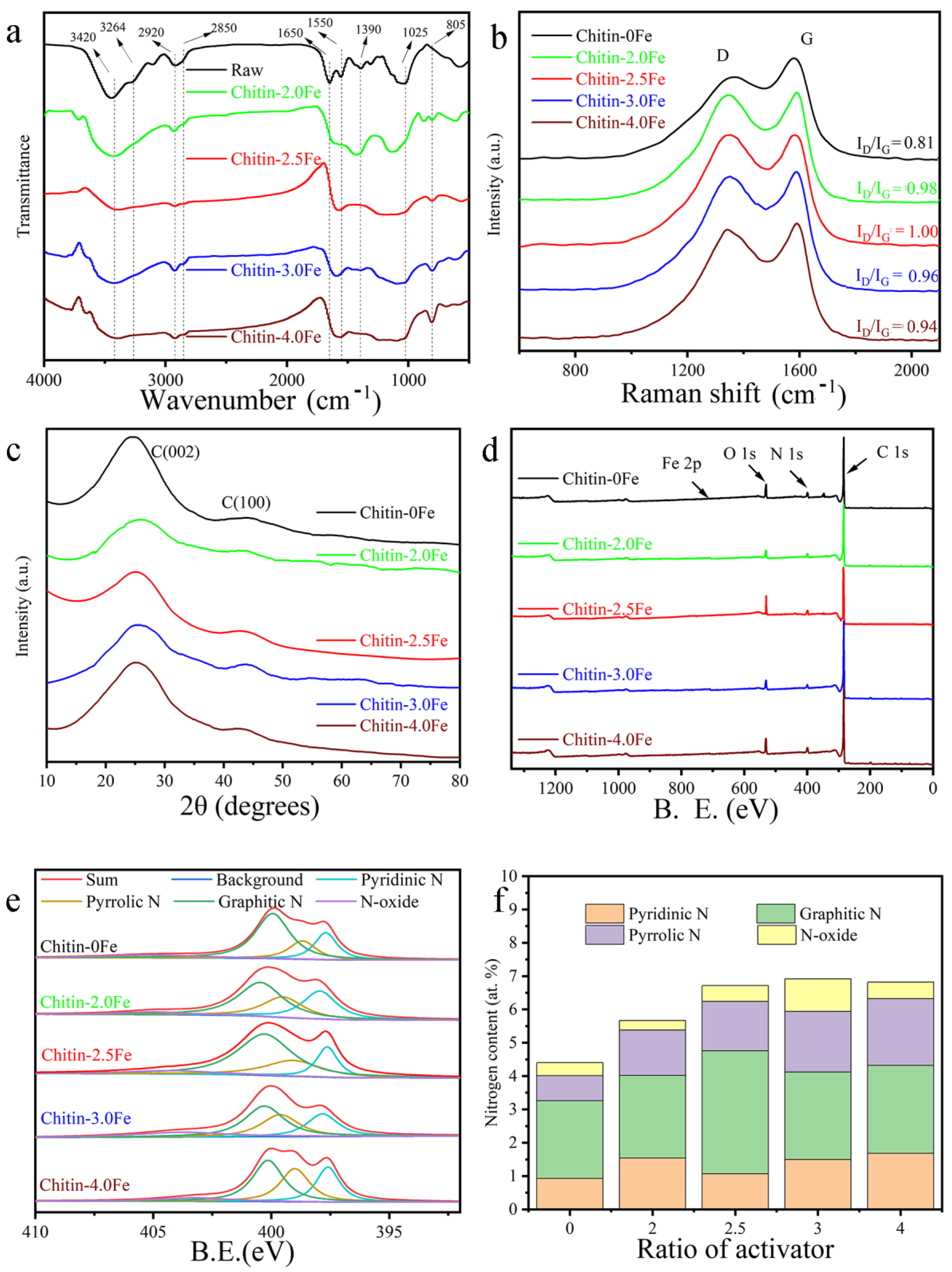
2.1. Preparation and General Characterization of Chitin-Derived Catalysts

Due to high crystallinity and stability, it is difficult to use chitin directly. Strong Lewis acids such as FeCl3 and ZnCl2 are usually used as activators to produce a high surface area, porous structure and intrinsic defects in biomass-derived catalysts [40]. Here, the chitin was initially pyrolyzed at 400 °C for 1 h and then 1 h at 900 °C at different ratios of chitin to FeCl3 (1:2, 1:2.5, 1:3 and 1:4). TGA was applied to investigate the weight loss during carbonization in the presence of FeCl3 (Figure S1) to understand the carbonization and activation processes. Chitins with FeCl3 exhibited two sharp drops at round 200 °C and 750 °C while a dramatic decline in the weight loss at around 400 °C was observed in the absence of FeCl3. These suggested that FeCl3 initially reacted with H2O to form FeOCl (Equation (S1)) and then Fe2O3 (Equation (S2)) with HCl release, corresponding to a sharper drop at around 200 °C, leading to the reduction in the crystallinity and stability of chitin. Then, as the temperature increased, the carbonization continued with the greatest mass loss rate while Fe2O3 gradually reduced to Fe3O4, FeO and Fe in step with the CO and CO2 release (Equations (S3)–(S7)).
The bands at 3420, 3255 and 3097 cm−1 corresponded to an intramolecular hydrogen bond, the intermolecular hydrogen bond CO–NH and the intermolecular NH of chitin, respectively, as shown in Figure 1a. The vibration at ~2900 cm−1 was attributed to the CH vibration, the peaks at 1650 cm−1 and 1550 cm−1 showed the presence of amide I and amide II, respectively, and the peaks at 1116 and 1025 cm−1 were assigned to the stretching vibrations of C–O–C [41]. The 1650 cm−1, 1550 cm−1 and 1116 cm−1 peaks disappeared after carbonization, indicating that the bonds in amide I and II and C–O–C were destroyed. The new peaks at 1600 cm−1 and 805 cm−1 for the activated catalysts became stronger with the ratio of Fe to chitin increasing, implying the formation of defect sites [42,43,44].
The defects and graphitization degrees of the obtained catalysts were then characterized. As shown in Figure 1b, two broad bands at ~1350 cm−1 and 1600 cm−1 were attributed to D-band for disordered carbon atoms and defects and G-band for an ordered graphitic vibration, respectively. The presence of FeCl3 during pyrolysis dramatically increased the ID/IG (G bands represent the graphite-type lattice vibrations and D bands reflect the disordered graphite lattice vibrations) values of chitin-derived carbon materials, indicating that the abundance of intrinsic defects in carbon-based catalysts [37,45,46] may arise from nonplanar microstructure distortions or lattice defects. A slightly higher ID/IG value suggested more intrinsic defects in chitin-2.5Fe that probably included lattice vacancies and edge dislocations. Consistent with the Raman results, chitin-0Fe exhibited a sharp peak at 2θ = ~26.9° that was associated with a characteristic peak of graphite and a broad peak centered at 2θ = ~43° (Figure 1c) that corresponded with a typical amorphous carbon structure in X-ray diffraction patterns [47]. By contrast, the presence of activator FeCl3 led to a decrease in the graphite and resulted in more amorphous carbon structures, as indicated by two broad peaks at around 26.9° and 43°. In addition, no sharp peak at 44.9° attributed to the iron plane (110) [48] was found.
The N, C, O and Fe contents in the prepared catalysts were determined using XPS. No Fe element was observed (Figure 1d), indicating that no doped Fe existed in the prepared catalysts. All the XPS and XRD results together indicated that no Fe element was present in the chitin-derived catalysts. The deconvolution of XPS spectra was performed to differentiate the N types present in the chitin-derived catalysts (Figure 1e). The XPS results illustrated four different nitrogen peaks of pyridinic nitrogen at 398.3 eV, pyrrolic nitrogen at 400.1 eV, graphitic nitrogen at 401.5 eV and oxidized nitrogen at 402.1 eV, which can affect the charge of N atoms and C atoms [32,33]. The increasing amount of FeCl3 during pyrolysis led to an elevation in the percentage of total N content in the chitin-derived catalysts, which reached its maximum at the ratio of 1:3. The total percentage of pyridinic and graphitic N reached the maximum at 1:2.5 (Figure 1f), but the percentage of pyridinic N reached the maximum at the ratio of 1:2.5. The total percentage of pyridinic and pyrrolic N, which only existed in the zigzag edge or the defect sites, increased due to the introduction of FeCl3, suggesting more defect sites, consistent with the Raman results (Figure 1b). In addition, the C/O and C/N atomic ratio reduced, but no further decrease was observed when the chitin/FeCl3 ratio was ≥1:2.5 (Figure S2 and Figure S3).

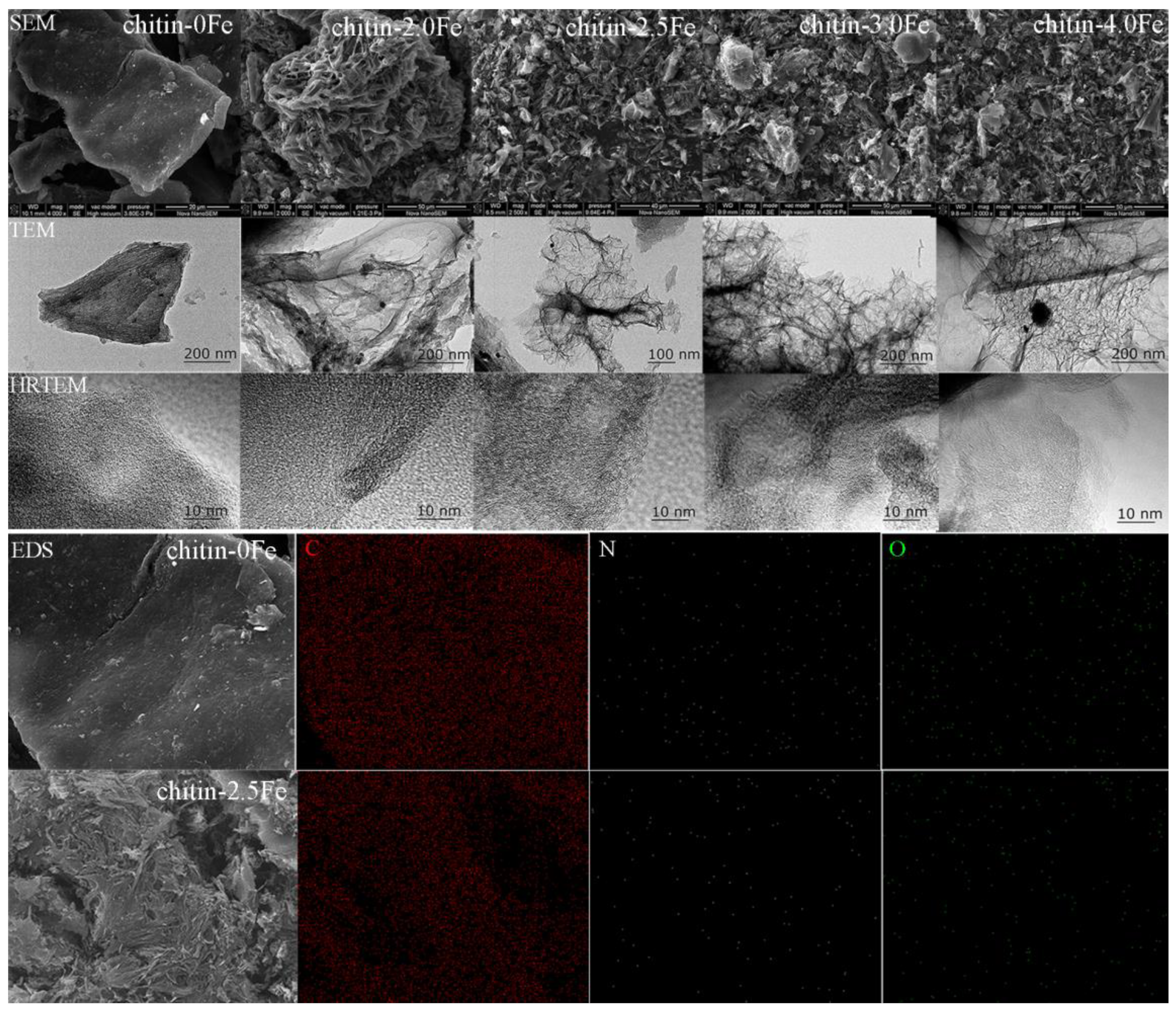
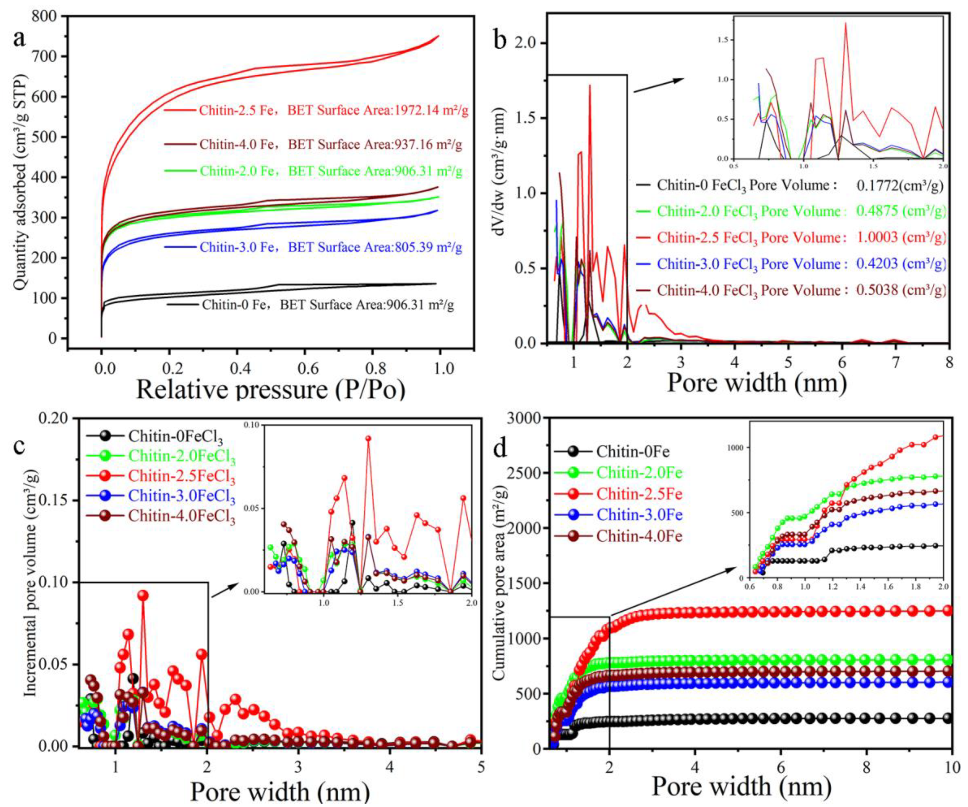
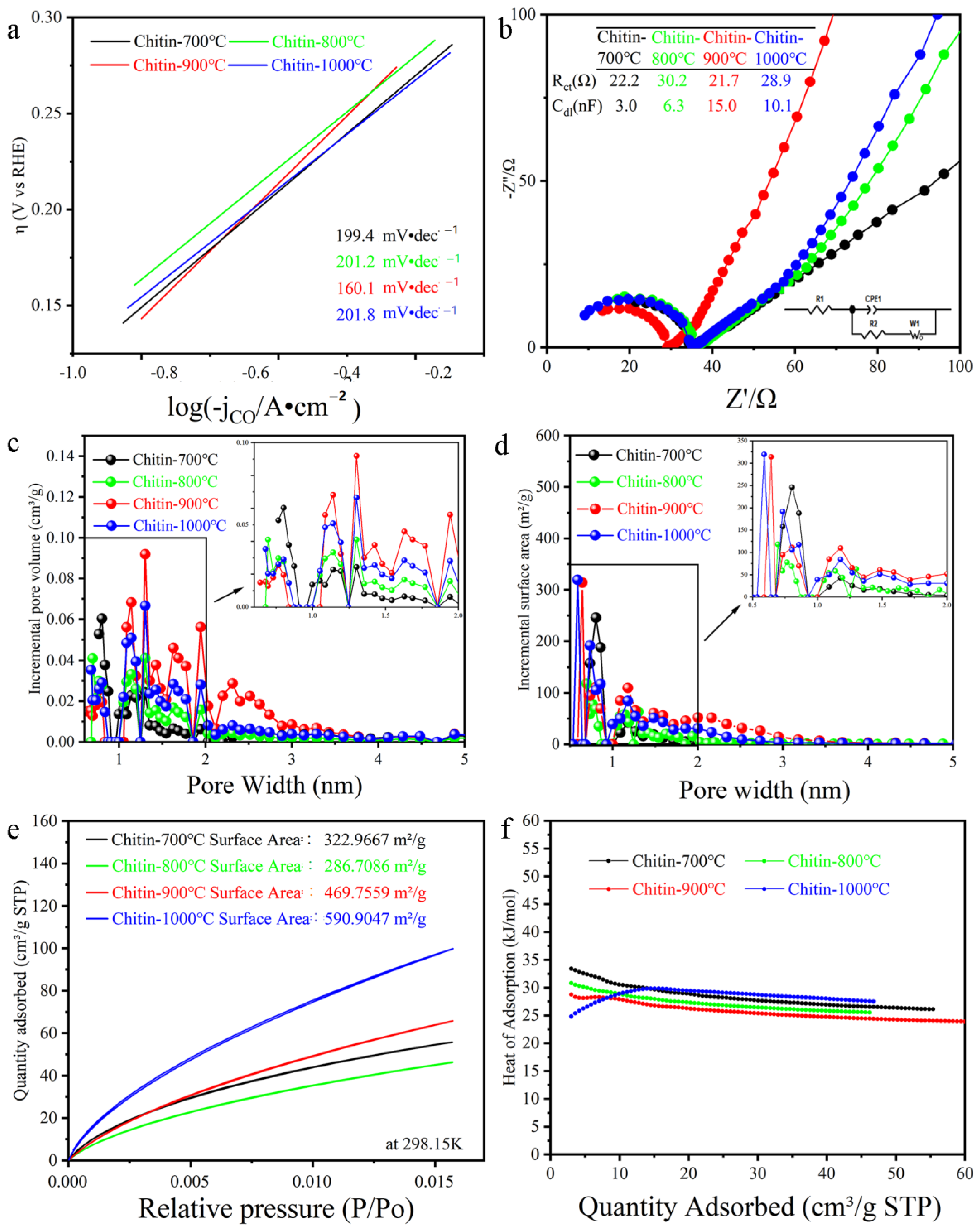
2.2. Morphology and Pore Characterization

Due to the removal of light and volatile matters during pyrolysis, SEM was employed to investigate the morphology and textural characteristics’ change after carbonization (Figure 2). The chitin-0Fe exhibited dense structure with a smooth surface. Gas generation during carbonization in the presence of FeCl3 manipulated the structures of the pores produced, leading to the hierarchical porous structure, which is beneficial for exposing more active sites as well as electrolyte diffusion. However, the pores appeared to be relatively less interconnected when the FeCl3 amount was increased from 1:2.5 to 1:4. All taken together, a 1:2.5 weight ratio of chitin to FeCl3 was deemed to be the optimal ratio. The chitin-derived catalysts with FeCl3 exhibited nanosheet-like morphology with wrinkles and a 3D cross-linked network structure. During the catalyst preparation, HCl was used to thoroughly wash out the Fe residues to obtain metal-free biomass-derived catalysts according to the previous studies [36,37]. However, the SEM images showed dark particles not only in chitin-2.0Fe, chitin-2.5Fe, chitin-3.5Fe and chitin-4.0Fe but also in chitin-0Fe, suggesting that the dark particles could be caused by deposition, further indicating no Fe element in the chitin-derived catalysts, as is consistent with the XPS and XRD results.
The FeCl3 activation led to a more amorphous structure, as is consistent with the Raman results (Figure 1c). A distorted graphitic lattice in the enlarged images in HR-TEM images was observed for the chitin-derived catalysts with FeCl3, suggesting more active sites, whereas the chitin-0Fe exhibited a clear (0 0 2) plane of graphitic lattice and a smooth surface, as is consistent with the XRD analysis results (Figure 1c). The presence of FeCl3 during pyrolysis clearly led to the amorphous structure, which is in line with the silk-derived catalysts prepared via pre-carbonization and activation using ZnCl2 [37] but not consistent with the N-doped carbon prepared from cedar with melamine [36]. The EDS results revealed that nitrogen, oxygen and carbon were evenly distributed.
The nitrogen adsorption/desorption isotherms, pore size distributions, incremental pore volume, cumulative pore volume and cumulative surface area are shown in Figure 3 and Figure S4, respectively. All the samples exhibited a typical type-I curve except for the chitin-2.5Fe (Figure 3a). FeCl3 improved the specific surface area and porosity via synergistic effects of carbon lattice expansion and chemical activation (Figure 3b–d). A sharp rise in the nitrogen adsorption at a low relative pressure (P/P0 < 0.01) indicated a high concentration of micropores in all of the samples. At a ratio of 1:2.5, an initial sharp rise in nitrogen uptake was observed, while a further substantial increase suggested a highly microporous and mesoporous structure owing to the Fe2O3 decomposition and CO and CO2 release (Equations (S3)–(S7)). Unlike the chitin-0Fe, the cumulative surface area and pore volume of other samples increased rapidly in the pore size region ranging from 0.7 nm to 1.1 nm; a further sharp increase was observed for the chitin-2.5Fe in the pore size region ranging from 1.1 nm to 3 nm in the somewhat mesoporous region. Moreover, in comparison with other conditions, the chitin-2.5Fe exhibited similar number of micro-pores (<1 nm), but remarkably more micro-pores (1–2 nm) and meso-pores (2–3 nm), showing the greatest surface volume and pore volume. An increasing slope at a relative pressure from 0.1 to 0.4 in the chitin-2.5Fe further suggested that the pores were wider, confirming the existence of meso-pores in the chitin-2.5Fe, implicating the improved mass transfer.

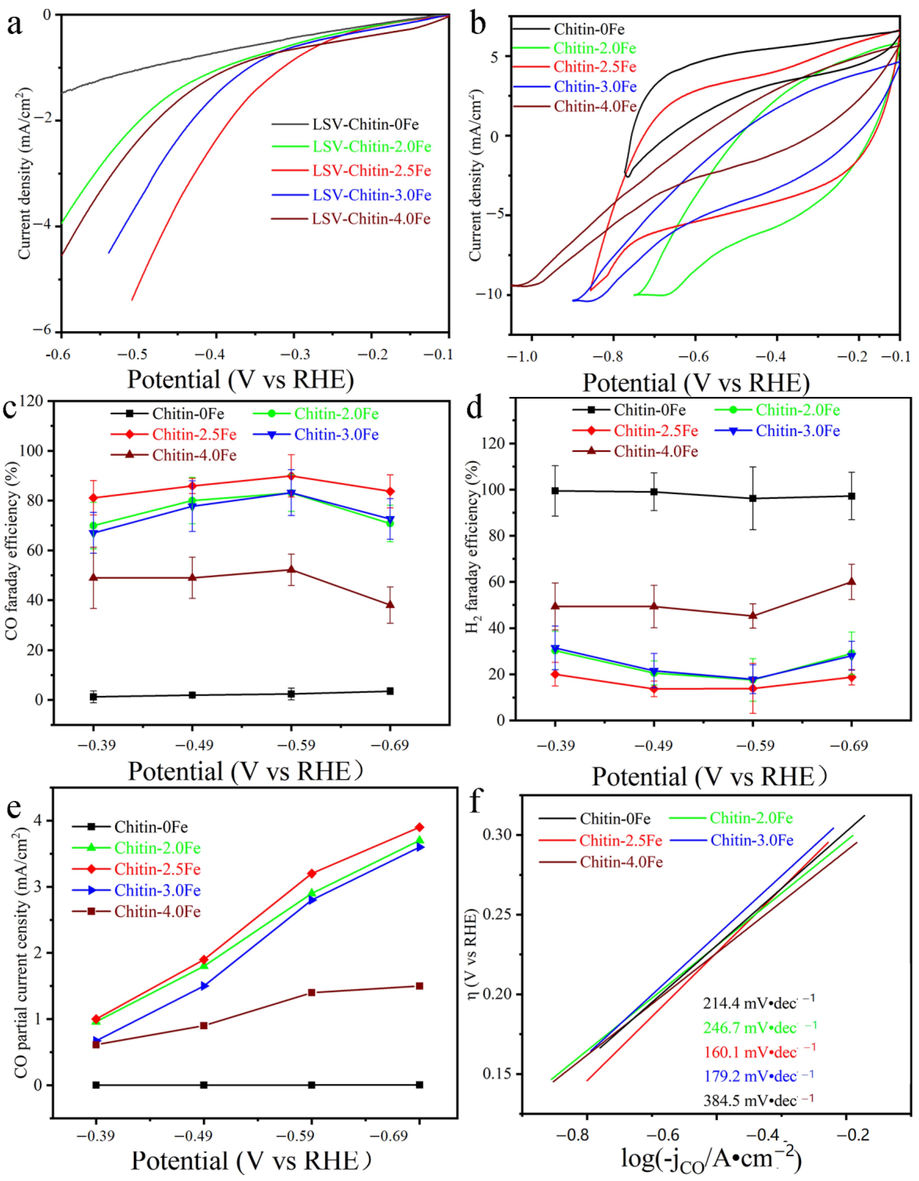
2.3. CO2RR Performance

The CO2RR performance was tested in an aqueous solution of 0.1 M KHCO3 with CO2 saturation. According to LSV and CV studies (Figure 4a,b), all the samples prepared with FeCl3 possessed a better ability of CO2RR than those prepared without FeCl3. The chitin-2.5Fe electrocatalysts exhibited a low onset potential and relatively higher reducing current than the others. The catalytic performance was evaluated under the constant potentials 0.39, −0.49, 0.59 and −0.69 V (vs. RHE). Since the summation of FE related to H2 and CO was nearly 100%, indicating that the gaseous products only included CO and H2 and no liquid products, it was found that FeCl3-activated catalysts enhanced the selectivity to CO at all tested potentials whereas chitin-0Fe displayed negligible activity for conversing CO2 to CO, which was perhaps mainly caused by nonporous morphology.
The chitin-2.5Fe exhibited higher FECO and less FEH2 at each applied potential than the others, reaching up to 80% of FECO even at an applied potential as low as −0.39 V (vs. RHE) and showing the highest FECO of around 90% at −0.59 V (vs. RHE) and strongest suppression of H2 evolution (Figure 4c,d). We also determined FECO and FEH2 of a carbon plate (Figure S7). Almost no CO was detected, indicating that the coating of chitin-derived led to the enhancement of FECO. Figure 4e shows that the partial current density (jCO) increased with the applied potentials from −0.39 to −0.69 V (vs. RHE) and followed the order chitin-2.5Fe > chitin-2.0Fe > chitin-3.0Fe > chitin-4.0Fe > chitin-0Fe. The chitin-2.5Fe possessed a maximum value at each potential, showing the highest jCO of ~3.5 mA/cm2 at −0.69 V (vs. RHE). The different trend between FECO and the percentage of pyridinic N in the catalyst suggested that the content of pyridinic N is not the only factor affecting the CO2RR performance. Compared with the other catalysts, the best performance by chitin-2.5Fe could result from the highest specific surface area, pore volume and the total content of pyridinic and graphitic nitrogen. As seen in Figure 1f, the chitin-2.5Fe contained much less pyridinic nitrogen, which could by a reason for no dramatically superior selectivity to CO over the chitin-2.0Fe and chitin-3.0Fe.
The Tafel slope was calculated to be 160.10 mV dec−1 for the chitin-2.5Fe (Figure 4f), suggesting that it offers more favorable kinetics for CO generation than the others. Considering the high CO2RR selectivity and high surface area, which is beneficial for exposing active sites on the surface of the catalyst during the CO2 electroreduction process, the ratio of chitin to FeCl3 at 1:2.5 was regarded as the best ratio for further preparing the chitin-derived electrocatalysts for CO2RR in this study.

2.4. CO2RR Performance over Chitin-Derived Catalysts Prepared at Different Temperatures

To investigate the pyrolysis temperature effect on the CO2RR performance, a series of catalysts was prepared at the temperatures of 700–1000 °C with chitin: FeCl3 at 1:2.5, denoted as chitin-700 °C, chitin-800 °C, chitin-900 °C and chitin-1000 °C. They exhibited porous structure and nanosheet morphology with more defects (Figure 5a,b and Figure S5). As seen in Figure 5c, the graphitic N content increased with the temperature until 900 °C, then a further rise in the calcination temperature resulted in diminishing the existing nitrogen functional groups (Figure 5c). The change trend in the pyridine and pyrrolic nitrogen content exhibited an inverse V shape (Figure 5c) while the C=O content displayed a V shape and the C–O content showed an S shape (Figure S6). PCD and maximum FE for CO over the chitin-700 °C, -800 °C and -900 °C showed a positive correlation with the graphitic N content and a negative correlation with the C=O content (Figure 5c and Figure S6) but no direct correlation with the pyridinic N, implying that the pyridinic nitrogen defect sites are not the only factor for contribution to FECO [36]. Despite higher nitrogen content in the chitin-800, it exhibited the similar FECO and FEH2 as the chintin-1000 °C (Figure 5d and Figure S7), suggesting that the positive effect of high nitrogen content was offset by its low surface area and pore volume (Figure 5e). Due to the local electronic redistribution caused by the presence of nitrogen and oxygen functional groups, the carbon sites in the chitin-800 °C possessed larger charge densities, further leading to higher PCD than the chitin-1000 °C (Figure 5c).
In comparison with the reported metal-free carbon nanotube-based electrocatalysts (Table 1), the chitin-900 °C prepared in this work exhibited higher FECO than MWCNT/Cc and g-C3N4/MWCNT [49,50], showed comparable FECO to NCNTs-CAN-850 and N-CNT but higher jCO [51,52] and exhibited similar FECO to NCNT-3-700 [53] but at lower overpotential. The chitin-900 manifested parallel FECO to porous nitrogen-doped carbon catalysts with sulfur/fluorine/phosphorous addition but higher jCO at a similar overpotential [54,55,56,57,58] and displayed much better CO2RR performance than the previous studies [34,59,60]. Compared with the N-doped electrocatalysts derived from biomass, the chitin-900 °C prepared using the simpler procedure showed high specific surface area [35,36,37] and better FECO [35].

2.5. Investigation of Carbon Electrocatalysts Mechanism for CO2RR

The Tafel plots were derived to explore electrodynamics for the CO formation (Figure 6a and Figure S8). The chitin-900 °C exhibited the lowest Tafel slope, suggesting the fastest kinetics for CO formation. In addition, the overpotential of the chitin-900 °C was lower than the others at the same exchange current density (Figure 6a and Figure S8), indicating that the chitin-900 °C was a better catalyst than the others. Since the Tafel slope is not close to 118 mV dec−1, a value for the rate determining the step at which CO2 obtains one electron to form the CO2•− key intermediate, the complexity of the reaction system is demonstrated. The EIS showed a single semi-circle in the frequency range of 101–105 Hz, revealing the single charge transfer process of CO2RR (Figure 6b). The chitin-900 °C showed the lowest interfacial charge transfer resistance (Rct), leading to rapid electron transfer in the CO2 reduction process [61], which is in line with the Tafel results. The EIS results (the inset in Figure 6b) further showed the highest double layer capacitance (Cdl) for the chintin-900 °C, suggesting that it contained a more active surface, leading to the CO2RR performance being enhanced.
Since CO and H2 are the only products produced, the CO2RR process is initiated by the adsorption of CO2 when CO2 approaches the surface, resulting in a partially negative and bound *CO2 intermediate, followed by a CO2•− or *COOH intermediate, subsequently forming a *CO species and CO release after desorption from the catalyst surface. Hence, we examined the CO2 adsorption of the prepared catalysts. It was found that the higher the pore volume and surface area of porous catalysts (<1 nm) were, the greater the CO2 adsorption, showing that the CO2 adsorption was correlated with ultra-narrow pores less than ≤1 nm in diameter (Figure 6c,d and Figure S9). Despite the fact that pyridine nitrogen and pyrrolic nitrogen are thought to efficiently bind with CO2 due to excess negative charges, no clear relationship between the CO2 adsorption with their content (Figure 5c and Figure 6e) was observed. All these results together indicated that the CO2 adsorption predominantly depends upon ultra-narrow pores while the nitrogen-content plays a complementary role.
∆Hads between the chitin-derived catalysts and CO2 were further determined, all in the typical physisorption range of 25.0–34 kJ/mol (Figure 6f). The higher the nitrogen content, the higher the initial ∆Hads, indicating that the initial ∆Hads was positively correlated with the nitrogen content, revealing that nitrogen functionalities enhanced interactions between CO2 molecules and the catalyst surface, further leading to the improved CO2 adsorption. With the CO2 coverage elevation, the ∆Hads gradually decreased except for the chitin-1000 °C (Figure 6f), implying less surface area occupied with nitrogen functional groups. In comparison with the chitin-700, the chitin-1000 °C contained less pyridinic and graphitic nitrogen but more CO2 adsorption and higher FECO, implying that the ultra-narrow pore is beneficial to the CO2 adsorption, which is further conducive to improving the electrical catalyst property.
Overall, the best CO2RR performance of the chitin-2.5Fe is associated with the synergetic effects of high pyridinic and graphitic nitrogen content for more active sites, more ultra narrow pores and meso-pores for facilitating CO2 adsorption and mass transfer, high surface area for providing more active surface and low interfacial charge transfer resistance for rapid electron transfer.

3. Materials and Methods

3.1. Materials

Chitin (99%) was purchased from Shenzhen Lefu Tech. (Shenzhen, Guangdong, China). Potassium bicarbonate (KHCO3, 99.5%) and FeCl3 (99%) were purchased from Wuxi Yatai United Chemical (Wuxi, Jiangsu, China). KHCO3 (99%) was purchased from Macklin (Shanghai, China). ZnCl2 (98%) was from Shanghai Taitan Tech. (Shanghai, China). Hydrochloric acid (HCl, 36%–38%), chitosan (degree of deacetylation 90%) and anhydrous ethanol were from Sinopharm Chemical Reagent (Shanghai, China). Nafion 117 (5%) and Nafion 117 membrane were purchased from DuPont (Wilmington, DE, USA). (NH4)2FeSO4 (98%) and K2FeO4 (98%) was purchased from Shanghai Aladdin Bio-Chem Technology (Shanghai, China). Carbon paper was purchased from Beijing JingLongTeTan Technology (Beijing, China). Unless otherwise mentioned, all chemicals were used as received without further purification. N2 and CO2 and Ar were obtained from Nanjing special gas (Nanjing, Jiangsu, China).

3.2. Biomass-Derived Electrocatalyst Preparation

Fine chitin and chitosan powders were mixed with an activator of anhydrous FeCl3 at a certain weight ratio in a porcelain boat. Then, the boat with the mixtures was placed into a tube furnace for 1 h of nitrogen exchange. The samples were then heated at 5 °C/min to 400 °C under steady N2 flow at 10 mL/min as a protective gas. After 1 h, the temperature continued to rise at a ramp rate of 5 °C/min. The catalysts were then prepared with the ratio of chitin to Fe at 1:2.5 at the different temperatures of 700, 800, 900 and 1000 °C for 1 h under an N2 atmosphere denoted as chitin-Fe-700, chitin-Fe-800, chitin-Fe-900 and chitin-Fe-1000, respectively. Furthermore, the catalysts were prepared with the various ratios of chitin to Fe at 1:2, 1:2.5, 1:3 and 1:4 at 1 h 400 °C and 1 h 900 °C under N2, denoted as chitin-2.0Fe, chitin-2.5Fe, chitin-3.5Fe and chitin-4.0Fe, respectively. For comparison, pure chitin-derived catalyst (chitin-0Fe) was also prepared in the absence of FeCl3. After activation and carbonization, the cooled catalysts were immersed in excess 0.1 M HCl and stirred for 24 h, then washed with 0.1 M HCl several times to remove all residues containing Fe [36,37], then thoroughly washed with deionized water until the pH reached neutral and then washed with ethanol. The catalysts were collected after filtration and dried in a vacuum oven at 60 °C overnight.

3.3. Electroreduction of CO2 and Electrochemical Characterizations

Electrochemical CO2 reduction reaction was carried out using a H-cell separated by Nafion 117 membrane with three electrodes on an electrochemical workstation (CHI 604e, Shanghai Zhenhua, Shanghai, China). A platinum foil (Jingke Instrument, Shanghai, China), an electrocatalyst-coated carbon plate with dimensions of 1 cm × 2 cm and a saturated calomel electrode (SCE) (Shanghai Chuxi, Shanghai, China) were used as the working electrode, the counter electrode and the reference electrode, respectively. The working electrode was prepared by mixing 5 mg of carbonized activated biomass-based catalyst with 480 μL ethanol, 480 μL deionized water and 50 μL Nafion solution, ultrasonicated for 1 h until the mixture became uniform. The mixture was then coated onto a carbon plate in an area of 1 cm × 1 cm on each side and dried overnight. Prior to the electroreduction of CO2, 30 mL of 1 M KHCO3 was used as an anolyte while 1 M KHCO3 saturated with CO2 (pH 7.4) was used as a catholyte. CO2 continued to flow into the catholyte at a rate of 30 mL/min during CO2RR. All the experiments were performed at 20 °C, giving the SCE a potential of +0.244 V. All the potentials performed in this study were referred to the RHE unless otherwise noted: E (vs. RHE) = E (vs. SCE) + 0.244 + 0.059 pH.
Cyclic voltammetry (CV) was carried out for 30 cycles from −0.6 to −2.0 V (vs. the Hg/Hg2Cl2/KCl electrode) at a scan rate of 50 mV·s−1. Linear sweep voltammetry (LSV) was carried out in a range between −0.39 and −1.79 V at a scan rate of 10 mV·s−1. Electrochemical impedance spectroscopy (EIS) analysis was performed at −0.91 V vs. SHE using a frequency module of the potentiostat in a range of 10 Hz–10,000 Hz (at 10 mV AC amplitude). The obtained data were fitted with Corrtest software. The CO2RR products were analyzed using a gas chromatography (GC9790, Zhejiang Fuli Instrument, Wenling, Zhejiang, China) with a Porapak N column and a 5A Molecular sieve (Wuhan Puli, Wuhan, Hubei, China). Faradaic efficiency (FE) and partial current density (PCD) were determined using the following equations:
F E   % = z n F   I × t × 100
P C D = F E   P r o d u c t × I A
where n is the number of moles of product, I is the total current at the time of sample collection (mA), z is the number of electrons, F is the Faradaic constant (C mol−1), t is the time for sample collection from the electrochemical cell (s), FE is the Faradaic efficiency and A is the electrode geometric area (cm2).

3.4. Characterization

Catalyst morphology and microstructure were analyzed using FEI Nova nano SEM 430 (FEI, Hillsboro, OR, USA) and a transmission electron microscope (TEM) (JEM-2100F, JEOL, Tokyo, Japan). X-ray diffraction (XRD) was carried out to determine crystalline structures of catalysts by Rigaku SmartLab SE (Tokyo, Japan) with CuKα as a radiation source. X-ray photoelectron spectroscopy (XPS) (Thermofisher Nexsa, Thermo Fisher, Illkirch-Graffenstaden, France) was used to characterize surface compositions using AlKα as a radiation source. The specific surface area was measured using an ASAP 2460 (Micromeritics, Norcross, GA, USA) with N2 adsorption/desorption at 77 K, and pore size distribution (PSD) was calculated by applying the NLDFT model. CO2 adsorption was performed at 273 and 298 K. A laser Raman spectrometer was applied to obtain a Raman spectrum in a scan range of 500–4000 cm−1 with a laser source of 532 nm (LabRAM HR Evolution, Horiba, Kyoto, Japan). The samples were observed using a nano SEM 430 at 50 eV–15 keV with an Everhart–Thornley Detector (ETD).

4. Conclusions

A nitrogen self-doped metal-free catalyst was prepared from inexpensive biomass-chitin via a simple one-step pyrolysis for electrochemical CO2RR. The as-prepared electrocatalyst of chitin-900 with a surface area of 1972 m2/g was found to convert CO2 into CO with FECO of ~90% and PCD of 3.3 mA·cm−2 at a potential of −0.59 V (vs. RHE). This good CO2RR performance results from the synergetic effects of plentiful active sites, rich ultra-micropores beneficial to CO2 adsorption, abundant mesopores for good CO2 transport, high total content of pyridinic and graphitic nitrogen and a low interfacial charge transfer resistance. This study shows the feasibility of an N self-doped biomass-derived catalyst for CO2RR with the potential for large-scale industrial applications.

Supplementary Materials

The following supporting information can be downloaded at: https://www.mdpi.com/article/10.3390/catal13050904/s1, Figure S1: TGA of chitin-derived catalysts prepared at different ratios of Chitin to FeCl3, Figure S2: Oxygen content of chitin-derived catalysts prepared at different ratios of Chitin to FeCl3, Figure S3: Carbon content of chitin-derived catalysts prepared at different ratios of Chitin to FeCl3, Figure S4: Cumulative pore volume of chitin-derived catalysts prepared at different ratios of Chitin to FeCl3, Figure S5: Morphology of chitin-derived catalysts prepared at different temperatures of 700–1000 °C, Figure S6: XPS analysis of chitin-derived catalysts prepared at different temperatures of 700–1000 °C, Figure S7: FE of catalysts. top: FEH2 of chitin-derived catalysts prepared at different temperatures of 700–1000 °C. bottom: FECO and FEH2 of a carbon plate without coating, Figure S8: LSV of chitin-derived catalysts prepared at different temperatures of 700–1000 °C, Figure S9: BET analysis of incremental pore volume and surface area for N2 adsorption at 273 K.

Author Contributions

Conceptualization, X.X.; methodology, P.S. and X.W.; validation, P.S. and N.A.; formal analysis, X.X. and M.Z.; investigation, P.S.; resources, K.Z.; data curation, X.W.; writing—original draft preparation, X.X.; writing—review and editing, X.X.; visualization, M.Z.; supervision, X.X.; project administration, X.X. and K.Z.; funding acquisition, X.X. All authors have read and agreed to the published version of the manuscript.

Funding

This work was supported by the National Natural Science Foundation of China (91534107 and 21978001), the leader in Academic and Technology in Anhui Provence (2021D306) and the Start Fund for Biochemical Engineering Research Centre from Anhui University of Technology.

Data Availability Statement

Data is contained within the article or Supplementary Materials.

Conflicts of Interest

The authors declare no conflict of interest.

References

  1. Akadiri, S.; Alola, A.A.; Olasehind-Williams, G.; Etokakpan, M.U. The role of electricity consumption, globalization and economic growth in carbon dioxide emissions and its implications for environmental sustainability targets. Sci. Total Environ. 2020, 708, 134653. [Google Scholar] [CrossRef]
  2. Ye, R.P.; Ding, J.; Gong, W.; Argyle, M.D.; Zhong, Q.; Wang, Y.; Russell, C.K.; Xu, Z.; Russell, A.G.; Li, Q.; et al. CO2 hydrogenation to high-value products via heterogeneous catalysis. Nat. Commun. 2019, 10, 5698. [Google Scholar] [CrossRef] [PubMed]
  3. Mustafa, A.; Lougou, B.G.; Shuai, Y.; Wang, Z.; Tan, H. Current technology development for CO2 utilization into solar fuels and chemicals: A review. J. Energy Chem. 2020, 49, 96–123. [Google Scholar] [CrossRef]
  4. Grim, R.G.; Huang, Z.; Guarnieri, M.T.; Ferrell, J.R.; Tao, L.; Schaidle, J.A. Transforming the carbon economy: Challenges and opportunities in the convergence of low-cost electricity and reductive CO2 utilization. Energy Environ. Sci. 2020, 13, 472–494. [Google Scholar] [CrossRef]
  5. Yu, J.; Wang, J.; Ma, Y.; Zhou, J.; Wang, Y.; Lu, P.; Yin, J.; Ye, R.; Zhu, Z.; Fan, Z. Recent progresses in electrochemical carbon dioxide reduction on copper-based catalysts toward multicarbon products. Adv. Funct. Mater. 2021, 31, 2102151. [Google Scholar] [CrossRef]
  6. Wang, S.; Kou, T.; Baker, S.E.; Duoss, E.B.; Li, Y. Electrochemical reduction of CO2 to alcohols: Current understanding, progress, and challenges. Adv. Energy Sustain. Res. 2022, 3, 2100131. [Google Scholar] [CrossRef]
  7. Wang, G.; Chen, J.; Ding, Y.; Cai, P.; Yi, L.; Li, Y.; Tu, C.; Hou, Y.; Wen, Z.; Dai, L. Electrocatalysis for CO2 conversion: From fundamentals to value-added products. Chem. Soc. Rev. 2021, 50, 4993–5061. [Google Scholar] [CrossRef]
  8. Hui, S.; Shaigan, N.; Neburchilov, V.; Zhang, L.; Malek, K.; Eikerling, M.; Luna, P.D. Three-dimensional cathodes for electrochemical reduction of CO2: From macro- to nano-engineering. Nanomaterials 2020, 10, 1884. [Google Scholar] [CrossRef]
  9. Zhang, L.; Zhao, Z.J.; Gong, J. Nanostructured materials for heterogeneous electrocatalytic CO2 reduction and their related reaction mechanisms. Angew. Chem. Int. Ed. 2017, 56, 11326–11353. [Google Scholar] [CrossRef]
  10. Kuhl, K.P.; Hatsukade, T.; Cave, E.R.; Abram, D.N.; Kibsgaard, J.; Jaramillo, T.F. Electrocatalytic conversion of carbon dioxide to methane and methanol on transition metal surfaces. J. Am. Chem. Soc. 2014, 136, 14107–14113. [Google Scholar] [CrossRef]
  11. Masa, J.; Andronescu, C.; Schuhmann, W. Electrocatalysis as the nexus for sustainable renewable energy: The Gordian Knot of activity, stability, and selectivity. Angew. Chem. Int. Ed. 2020, 59, 15298–15312. [Google Scholar] [CrossRef] [PubMed]
  12. Mariano, R.G.; McKelvey, K.; White, H.S.; Kanan, M.W. Selective increase in CO2 electroreduction activity at grain-boundary surface terminations. Science 2017, 358, 1187–1192. [Google Scholar] [CrossRef] [PubMed]
  13. Singh, M.R.; Goodpaster, J.D.; Weber, A.Z.; Head-Gordon, M.; Bell, A.T. Mechanistic insights into electrochemical reduction of CO2 over Ag using density functional theory and transport models. Proc. Natl. Acad. Sci. USA 2017, 114, E8812–E8821. [Google Scholar] [CrossRef] [PubMed]
  14. Marcandalli, G.; Goyal, A.; Koper, M.T. Electrolyte Effects on the Faradaic efficiency of CO2 reduction to CO on a gold electrode. ACS Catal. 2021, 11, 4936–4945. [Google Scholar] [CrossRef] [PubMed]
  15. Gao, D.; Arán-Ais, R.M.; Jeon, H.S. Rational catalyst and electrolyte design for CO2 electroreduction towards multicarbon products. Nat. Catal. 2019, 2, 198–210. [Google Scholar] [CrossRef]
  16. Bonetto, R.; Crisanti, F.; Sartorel, A. Carbon dioxide reduction mediated by iron catalysts: Mechanism and intermediates that guide selectivity. ACS Omega 2020, 5, 21309–21319. [Google Scholar] [CrossRef]
  17. Zheng, T.; Jiang, K.; Ta, N.; Hu, Y.; Zeng, J.; Liu, J.; Wa, H. Large-scale and highly selective CO2 electrocatalytic reduction on nickel single-atom catalyst. Joule 2019, 3, 265–278. [Google Scholar] [CrossRef]
  18. Wen, G.; Gu, Q.; Liu, Y.; Schlögl, R.; Wang, C.; Tian, Z.; Su, D.S. Biomass-derived graphene-like carbon: Efficient metal-free carbocatalysts for epoxidation. Angew. Chem. Int. Ed. 2018, 57, 16898–16902. [Google Scholar] [CrossRef]
  19. Duan, X.; Xu, J.; Wei, Z.; Ma, J.; Guo, S.; Wang, S.; Liu, H.; Dou, S. Metal-free carbon materials for CO2 electrochemical reduction. Adv. Mater. 2017, 29, 1701784. [Google Scholar] [CrossRef]
  20. Liu, D.; Dai, L.; Lin, X.; Chen, J.F.; Zhang, J.; Feng, X.; Müllen, K.; Zhu, X.; Dai, S. Chemical approaches to carbon-based metal-free catalysts. Adv. Mater. 2019, 31, 1804863. [Google Scholar] [CrossRef]
  21. Vasileff, A.; Zheng, Y.; Qiao, S.Z. Carbon solving carbon’s Problems: Recent progress of nanostructured carbon-based catalysts for the electrochemical reduction of CO2. Adv. Energy Mater. 2017, 7, 1700759. [Google Scholar] [CrossRef]
  22. Liu, S.; Yang, H.; Su, X.; Ding, J.; Mao, Q.; Huang, Y.; Zhang, T.; Liu, B. Rational design of carbon-based metal-free catalysts for electrochemical carbon dioxide reduction: A review. J. Energy Chem. 2019, 36, 95–105. [Google Scholar] [CrossRef]
  23. Xue, D.; Xia, H.; Yan, W.; Zhang, J.; Mu, S. Defect engineering on carbon-based catalysts for electrocatalytic CO2 reduction. Nano Micro Lett. 2021, 13, 5. [Google Scholar] [CrossRef] [PubMed]
  24. Yan, X.C.; Jia, Y.; Odedairo, T.; Zhao, X.; Jin, Z.; Zhu, Z.H.; Yao, X.D. Activated carbon becomes active for oxygen reduction and hydrogen evolution reactions. Chem. Commun. 2016, 52, 8156–8159. [Google Scholar] [CrossRef] [PubMed]
  25. Zhou, Y.; Che, F.; Liu, M.; Zou, C.; Liang, Z.; Luna, P.D.; Yuan, H.; Li, J.; Wang, Z.; Xie, H.; et al. Dopant-induced electron localization drives CO2 reduction to C2 hydrocarbons. Nat. Chem. 2018, 10, 974–980. [Google Scholar] [CrossRef]
  26. Wang, Y.; Han, P.; Lv, X.; Zhang, L.; Zheng, G. Defect and interface engineering for aqueous electrocatalytic CO2 reduction. Joule 2018, 2, 2551–2582. [Google Scholar] [CrossRef]
  27. Li, H.; Xiao, N.; Hao, M.; Song, X.; Wang, Y.; Ji, Y.; Liu, C.; Li, C.; Guo, Z.; Zhang, F.; et al. Efficient CO2 electroreduction over pyridinic-N active sites highly exposed on wrinkled porous carbon nanosheets. Chem. Eng. J. 2018, 351, 613–621. [Google Scholar] [CrossRef]
  28. Gao, T.; Xie, T.; Han, N.; Wang, S.; Sun, K.; Hu, C.; Chang, Z.; Pang, Y.; Zhang, Y.; Luo, L.; et al. Electronic structure engineering of 2D carbon nanosheets by evolutionary nitrogen modulation for synergizing CO2 electroreduction. ACS Appl. Energy Mater. 2019, 2, 3151–3159. [Google Scholar] [CrossRef]
  29. Liu, S.; Yang, H.; Huang, X.; Liu, L.; Cai, W.; Gao, J.; Li, X.; Zhang, T.; Huang, Y.; Liu, B. Identifying active sites of nitrogen-doped carbon materials for the CO2 reduction reaction. Adv. Funct. Mater. 2018, 28, 1800499. [Google Scholar] [CrossRef]
  30. Wu, J.; Liu, M.; Sharma, P.P.; Yadav, R.M.; Ma, L.; Yang, Y.; Zou, X.; Zhou, X.D.; Vajtai, R.; Yakobson, B.I.; et al. Incorporation of nitrogen defects for efficient reduction of CO2 via two-electron pathway on three-dimensional graphene foam. Nano Lett. 2016, 16, 466–470. [Google Scholar] [CrossRef]
  31. Han, P.; Yu, X.; Yuan, D.; Kuang, M.; Wang, Y.; Al-Enizi, A.M.; Zheng, G. Defective graphene for electrocatalytic CO2 reduction. J. Colloid Interf. Sci. 2019, 534, 332–337. [Google Scholar] [CrossRef] [PubMed]
  32. Wang, W.; Shang, L.; Chang, G.; Yan, C.; Shi, R.; Zhao, Y.; Waterhouse, G.I.; Yang, D.; Zhang, T. Intrinsic carbon-defect-driven electrocatalytic reduction of carbon dioxide. Adv. Mater. 2019, 31, 1808276. [Google Scholar] [CrossRef] [PubMed]
  33. Li, R.; Zhou, Y.; Li, W.; Zhu, J.; Huang, W. Structure engineering in biomass-derived carbon materials for electrochemical energy storage. Research 2020, 2020, 8685436. [Google Scholar] [CrossRef] [PubMed]
  34. Li, W.L.; Herkt, B.; Seredych, M.; Bandosz, T.J. Pyridinic-N groups and ultramicropore nanoreactors enhance CO2 electrochemical reduction on porous carbon catalysts. Appl. Catal. B Environ. 2017, 207, 195–206. [Google Scholar] [CrossRef]
  35. Li, F.W.; Xue, M.Q.; Knowles, G.P.; Chen, L.; MacFarlane, D.R.; Zhang, J. Porous nitrogen-doped carbon derived from biomass for electrocatalytic reduction of CO2 to CO. Electrochim. Acta 2017, 245, 561–568. [Google Scholar] [CrossRef]
  36. Hao, X.; An, X.; Patil, A.M.; Wang, P.; Ma, X.; Du, X.; Hao, X.; Abudula, A.; Guan, G. Biomass-derived N-doped carbon for efficient electrocatalytic CO2 reduction to CO and Zn−CO2 batteries. ACS Appl. Mater. Interfaces 2021, 13, 3738–3747. [Google Scholar] [CrossRef]
  37. Chen, M.; Wang, S.; Zhang, H.; Zhang, P.; Tian, Z.; Lu, M.; Xie, X.; Huang, L.; Huang, W. Intrinsic defects in biomass-derived carbons facilitate electroreduction of CO2. Nano Res. 2020, 13, 729–735. [Google Scholar] [CrossRef]
  38. Nguyen, T.D.; Shopsowitz, K.E.; MacLachlan, M.J. Mesoporous nitrogen-doped carbon from nanocrystalline chitin assemblies. J. Mater. Chem. A 2014, 2, 5915–5921. [Google Scholar] [CrossRef]
  39. Wu, X.; Li, S.; Wang, B.; Liu, J.; Yu, M. From biomass chitin to mesoporous nanosheets assembled loofa sponge-like N-doped carbon/g-C3N4 3D network architectures as ultralow-cost bifunctional oxygen catalysts. Microporous Mesoporous Mater. 2017, 240, 216–226. [Google Scholar] [CrossRef]
  40. Hayashi, J.; Kazehaya, A.; Muroyama, K.; Watkinson, A.P. Preparation of activated carbon from lignin by chemical activation. Carbon 2000, 38, 1873–1878. [Google Scholar] [CrossRef]
  41. Sedaghat, F.; Yousefzadi, M.; Toiserkani, H.; Najafipour, S. Chitin from Penaeus merguiensis via microbial fermentation processing and antioxidant activity. Int. J. Biol. Macromol. 2016, 82, 279–283. [Google Scholar] [CrossRef]
  42. Chinnathambi, A.; Alahmad, T.A. Facile synthesis of Fe3O4 anchored polyaniline intercalated graphene oxide as an effective adsorbent for the removal of hexavalent chromium and phosphate ions. Chemosphere 2021, 272, 129851. [Google Scholar] [CrossRef]
  43. Muniandy, L.; Adam, F.; Mohamed, A.R.; Iqbal, A.; Rahman, N.R. Cu2+ coordinated graphitic carbon nitride (Cu-g-C3N4) nanosheets from melamine for the liquid phase hydroxylation of benzene and VOCs. Appl. Surf. Sci. 2017, 39, 43–55. [Google Scholar] [CrossRef]
  44. Dou, H.; Chen, L.; Zheng, S.; Zhang, Y.; Xu, G.Q. Band structure engineering of graphitic carbon nitride via Cu2+/Cu+ doping for enhanced visible light photoactivity. Mater. Chem. Phys. 2018, 214, 482–488. [Google Scholar] [CrossRef]
  45. Guo, K.; Li, N.; Bao, L.; Lu, X. Fullerenes and derivatives as electrocatalysts: Promises and challenges. Green Energy Environ. 2022, in press. [Google Scholar] [CrossRef]
  46. Zhou, Z.-W.; He, Z.-M.; Guo, K.; Huang, K.-K.; Lu, X. Recent Advances in Intrinsic Defects of Carbon-Based Metal-Free Electrocatalysts. Chin. J. Inorg. Chem. 2022, 38, 2113–2126. [Google Scholar]
  47. Zhou, Y.; Ma, R.; Candelaria, S.L.; Wang, J.; Liu, Q.; Uchaker, E.; Li, P.; Chen, Y.; Cao, G. Phosphorus/sulfur Co-doped porous carbon with enhanced specific capacitance for supercapacitor and improved catalytic activity for oxygen reduction reaction. J. Power Sources 2016, 314, 39–48. [Google Scholar] [CrossRef]
  48. Khezri, S.H.; Yazdani, A.; Khordad, R. Pure iron nanoparticles prepared by electric arc discharge method in ethylene glycol. Eur. Phys. J. Appl. Phys. 2012, 59, 30401. [Google Scholar] [CrossRef]
  49. Tuci, G.; Filippi, J.; Ba, H.; Rossin, A.; Luconi, L.; Pham-Huu, C.; Vizza, F.; Giambastiani, G. How to teach an old dog new (electrochemical) tricks: Aziridine functionalized CNTs as efficient Electrocatalysts for the selective CO2 Reduction to CO. J. Mater. Chem. A 2018, 6, 16382–16389. [Google Scholar] [CrossRef]
  50. Lu, X.; Tan, T.H.; Ng, Y.H.; Amal, R. Highly selective and stable reduction of CO2 to CO by a graphitic carbon nitride/carbon nanotube composite electrocatalyst. Chem. Eur. J. 2016, 22, 11991–11996. [Google Scholar] [CrossRef]
  51. Sharma, P.P.; Wu, J.; Yadav, R.M.; Liu, M.; Wright, C.J.; Tiwary, C.S.; Yakobson, B.I.; Lou, J.; Ajayan, P.M.; Zhou, X.D. Nitrogen-doped carbon nanotube arrays for High-efficiency electrochemical reduction of CO2: On the understanding of defects, defect density, and selectivity. Angew. Chem. Int. Ed. 2015, 54, 13701–13705. [Google Scholar] [CrossRef]
  52. Wu, J.; Yadav, R.M.; Liu, M.; Sharma, P.P.; Tiwary, C.S.; Ma, L.; Zou, X.; Zhou, X.D.; Yakobson, B.I.; Lou, J.; et al. Achieving Highly efficient, selective, and stable CO2 reduction on nitrogen-doped carbon nanotubes. ACS Nano 2015, 9, 5364–5371. [Google Scholar] [CrossRef] [PubMed]
  53. Xu, J.; Kan, Y.; Huang, R.; Zhang, B.; Wang, B.; Wu, K.H.; Lin, Y.; Sun, X.; Li, Q.; Centi, G.; et al. Revealing the origin of activity in nitrogen-doped nanocarbons towards electrocatalytic reduction of carbon dioxide. ChemSusChem 2016, 9, 1085–1089. [Google Scholar] [CrossRef]
  54. Pan, F.; Li, B.; Deng, W.; Du, Z.; Gang, Y.; Wang, G.; Li, Y. Promoting electrocatalytic CO2 reduction on nitrogen-doped carbon with sulfur addition. Appl. Catal. B-Environ. 2019, 252, 240–249. [Google Scholar] [CrossRef]
  55. Pan, F.; Li, B.; Xiang, X.; Wang, G.; Li, Y. Efficient CO2 electroreduction by highly dense and active pyridinic nitrogen on holey carbon layers with fluorine engineering. ACS Catal. 2019, 9, 2124–2133. [Google Scholar] [CrossRef]
  56. Liu, T.; Ali, S.; Lian, Z.; Si, C.; Su, D.S.; Li, B. Phosphorus-doped onion-like carbon for CO2 electrochemical reduction: The decisive role of the bonding configuration of phosphorus. J. Mater. Chem. A 2018, 6, 19998–20004. [Google Scholar] [CrossRef]
  57. Liu, W.; Qi, J.; Bai, P.; Zhang, W.; Xu, L. Utilizing spatial confinement effect of N atoms in micropores of coal-based metal-free material for efficiently electrochemical reduction of carbon dioxide. Appl. Catal. B-Environ. 2020, 272, 118974. [Google Scholar] [CrossRef]
  58. Li, W.; Fechler, N.; Bandosz, T.J. Chemically heterogeneous nitrogen sites of various reactivity in porous carbons provide high stability of CO2 electroreduction. Appl. Catal. B Environ. 2018, 234, 39–49. [Google Scholar] [CrossRef]
  59. Daiyan, R.; Tan, X.; Chen, R.; Saputera, W.H.; Tahini, H.A.; Lovell, E.; Ng, Y.H.; Smith, S.C.; Dai, L.; Lu, X.; et al. Electroreduction of CO2 to CO on a mesoporous carbon catalyst with progressively removed nitrogen moieties. ACS Energy Lett. 2018, 3, 2292–2298. [Google Scholar] [CrossRef]
  60. Li, W.; Seredych, M.; Rodríguez-Castellón, E.; Bandosz, T.J. Metal-free nanoporous carbon as a catalyst for electrochemical reduction of CO2 to CO and CH4. ChemSusChem 2016, 9, 606–616. [Google Scholar] [CrossRef]
  61. Murthy, A.P.; Theerthagiri, J.; Madhavan, J. Insights on Tafel constant in the analysis of hydrogen evolution reaction. J. Phys. Chem. C 2018, 122, 23943–23949. [Google Scholar] [CrossRef]
Figure 1. Characterization of chitin-derived catalysts prepared with different ratios of chitin to FeCl3. (a). FTIR, (b). Raman, (c). XRD, (d,e). XPS, (f). N content.
Catalysts 13 00904 g001
Figure 2. Morphological characterization for prepared catalysts obtained at different ratios of chitin to FeCl3.
Catalysts 13 00904 g002
Figure 3. Pore characterization of the catalysts prepared at various ratios of chitin to FeCl3. (a). N2 absorption/desorption at 77 K, (b). Pore distribution, (c). Incremental pore volume, (d). Cumulative pore area.
Catalysts 13 00904 g003
Figure 4. Electrocatalytic CO2RR performance over the chitin-derived catalysts prepared at different weight ratios of chitin to FeCl3. (a). LSV, (b). CV, (ce). FECO and FEH2 and PCD for CO, (f). Tafel slope.
Catalysts 13 00904 g004
Figure 5. Characterization of chitin-derived catalysts prepared at different temperatures and their CO2RR performance. (a). SEM and TEM at 1000 °C, (b). FECO, (c). Nitrogen contents and PCD at −0.59 V vs. RHE, (d). Raman, (e). Pore volume and surface area.
Catalysts 13 00904 g005
Figure 6. Tafel, EIS and CO2 absorption heat of chitin-derived catalysts. (a). Tafel slope, (b). EIS analysis conducted at the potential of −0.59 V vs. RHE, (c). BET analysis of incremental pore volume and surface area for N2 adsorption at 273 K, (d,e). CO2 isotherm absorption at 25 and 0 °C, (f). CO2 absorption heat.
Catalysts 13 00904 g006
Table 1. Catalytic performance of reported metal-free catalysts for electrochemical reduction of CO2 to CO.
CatalystSpecific Surface Area (m2/g)Electrolyte
(M)
Potential
(V vs. RHE)
jCO
(mA/cm2)
FECO
(%)
Ref
MWCNT/Cc 0.1 KHCO30.560.2788[49]
NCNTs-CAN-850 0.1 KHCO31.05480[51]
N-CNT 0.1 KHCO30.821.080[52]
NCNT-3-700 0.5 KHCO30.95.38~90[53]
g-C3N4/MWCNT123.40.1 KHCO30.640.5560[50]
NS-C-9001600.1 KHCO30.62.6392[54]
NF-C-9501970.1 KHCO30.61.990[55]
P-OLC3380.5 NaHCO30.94.981[56]
NPC-9005450.5 KHCO30.672.395[57]
SaU-9006620.1 KHCO30.85222[58]
NRMC-900-38320.1 KHCO30.62.982[59]
NDC-70012690.5 NaHCO30.7112.584[35]
S, N-carbon13320.1 KHCO30.990.4711.3[60]
N-BAX-M-95014940.1 KHCO30.660.740[34]
A-350-100015002 KHCO31.11.589[37]
CB-NGC-21673.60.1 KHCO30.563.791[36]
Chitin-900 °C19720.1 KHCO30.593.390This work
Disclaimer/Publisher’s Note: The statements, opinions and data contained in all publications are solely those of the individual author(s) and contributor(s) and not of MDPI and/or the editor(s). MDPI and/or the editor(s) disclaim responsibility for any injury to people or property resulting from any ideas, methods, instructions or products referred to in the content.

