Article

The Effect of Chlorine Modification of Precipitated Iron Catalysts on Their Fischer–Tropsch Synthesis Properties

National Institute of Clean-and-Low-Carbon Energy, Beijing 102211, China
*
Authors to whom correspondence should be addressed.
Catalysts 2022, 12(8), 812; https://doi.org/10.3390/catal12080812
Submission received: 20 June 2022 / Revised: 8 July 2022 / Accepted: 22 July 2022 / Published: 24 July 2022
(This article belongs to the Special Issue Development of Novel Catalysts for Fischer–Tropsch Synthesis)

Abstract

:
Precipitated iron Fischer–Tropsch synthesis catalysts impregnated with chlorine were prepared and their Fischer–Tropsch synthesis performances were tested in a 1 L stirred tank reactor. The results showed that the chlorine modification had a significant influence on the Fischer–Tropsch synthesis performance of the precipitated iron catalyst. Compared with the catalyst without the chlorine modification, the catalyst containing about 0.1 wt% chlorine was deactivated by about 40% and the catalyst containing about 1 wt% chlorine was deactivated by about 65%. The textural properties, phase, reduction properties, and chlorine adsorption state of the catalysts before and after the Fischer–Tropsch synthesis were characterized. The strong interaction between chlorine and iron in the catalyst hindered the reduction and carbonization of the catalyst, which was the reason for the deactivation of the catalyst caused by the chlorine modification.

Graphical Abstract

1. Introduction

A precipitated iron Fischer–Tropsch synthesis catalyst is a widely used type of catalyst in industrial-scale Fischer–Tropsch synthesis. However, due to the chemical properties of iron, precipitated iron catalysts suffer from a high deactivation rate with their industrial application. It is generally believed that there are four reasons for the deactivation of iron-based Fischer–Tropsch catalysts: a loss of active phases; sintering; carbon deposition; and poisoning [1]. Most of the substances that easily cause the poisoning of iron-based Fischer–Tropsch synthesis catalysts are electronegative elements such as sulfur and ammonia [2,3,4]. Sulfur is the most comprehensively studied substance at present. The syngas obtained from a coal conversion usually contains sulfur. However, there are few studies on the effect of chlorine, which is also an electronegative element that can cause catalyst deactivation. It has been reported in the literature that synthesis gas derived from a biomass can contain chlorinated impurities at significant concentrations [5,6,7]. Therefore, it is important to study the effect of the chlorine of iron-based catalysts on their Fischer–Tropsch synthesis properties in order to promote the application of iron-based catalysts in Fischer–Tropsch synthesis using a biomass as a gas source. The application of cheap iron-based catalysts helps to increase the economy of the biomass conversion process and promote the utilization of green energy.
Davis et al. added aqueous solutions of KCl, NaCl, and HCl to syngas and studied their effects on the performance of precipitated iron catalysts for Fischer–Tropsch synthesis [8,9,10]. The experimental results showed that 23~40 ppm HCl in syngas significantly affected the performance of the catalyst whereas KCl and NaCl had little effect on the performance of the catalyst. Bordoloi et al. [11] found that when an FeCuK/Al2O3 catalyst contained more than 2000 ppm chlorine, the CO conversion of the catalyst significantly decreased, but the selectivity of C2~4 olefins significantly increased due to the inhibited hydrogen adsorption.
It can be seen from the above research that chlorine may have a significant impact on the Fischer–Tropsch synthesis performance of a catalyst. It is necessary to further study the effect of chlorine on the Fischer–Tropsch synthesis performance of precipitated iron catalysts. In this paper, precipitated iron Fischer–Tropsch synthesis catalysts were modified with chlorine and their performances of Fischer–Tropsch synthesis were tested in a 1 L stirred slurry reactor. The textural properties, phase, reduction properties, and chlorine adsorption state of the catalysts before and after the reaction were investigated by means of N2 physical adsorption, X-ray fluorescence (XRF), X-ray diffraction (XRD), transmission electron microscopy (TEM), Mössbauer spectroscopy (MEMS), H2 temperature-programmed reduction (H2-TPR), and X-ray photoelectron spectroscopy (XPS), which aimed to clarify the effect of the chlorine modification on the Fischer–Tropsch synthesis performance of the precipitated iron catalysts.

2. Results and Discussion

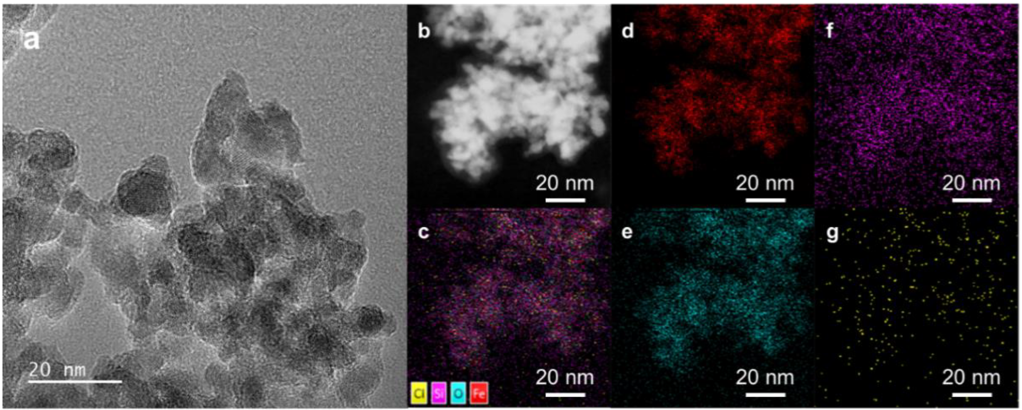
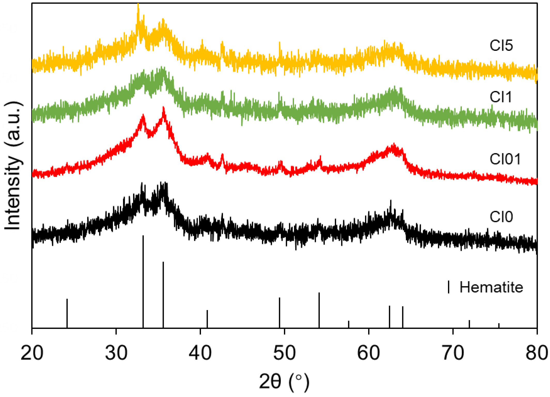
2.1. Characterization of the Freshly Prepared Catalysts

The composition and textural properties of the chlorinated precipitated iron Fischer–Tropsch synthesis catalysts were characterized before a catalytic performance evaluation. The compositions measured by XRF as well as the specific surface area, pore volume, and average pore size measured by N2 physical adsorption are shown in Table 1. The chlorine contents of the catalysts measured by XRF were equal or slightly lower than the targeted amount. Even if chlorine was not added during the preparation process, the Cl0 catalyst still contained 0.08 parts of chlorine per 100 parts of Fe2O3, which may have been caused by impurities in the reagents or environment issues. The pore volume and average pore size of Cl0, Cl01, Cl1, and Cl5 were almost the same. However, the impregnation of chlorine had a certain impact on the specific surface area of the catalysts, especially on Cl5. The specific surface area of Cl5 was reduced to 123.0 m2·g−1 compared with 140.8 m2·g−1 of Cl0. Therefore, in order to exclude the influence of a specific surface area reduction on the catalyst activity, only Cl0, Cl01, and Cl1 were tested for Fischer–Tropsch synthesis.
The morphology and element distribution of the Cl1 catalyst was measured through TEM, HAADF-STEM, and STEM-EDS. The TEM image (Figure 1a) showed that the freshly prepared Cl1 was composed of small grains of about 2 nm. The STEM-EDS images (Figure 1c–g) showed that the Fe, O, and Si elements were evenly distributed in the same position. Although the signal was weak due to the low chlorine content, it could still be seen that the impregnated chlorine was evenly distributed over the catalyst surface.
The XRD patterns of four freshly prepared precipitated iron catalysts with chlorine are shown in Figure 2. It could be seen from the patterns that the freshly prepared catalysts were amorphous and the characteristic diffraction peaks were consistent with hematite (PDF 79-1741). The diffraction peaks at 33.2°, 35.6°, 40.8°, 49.5°, 54.0°, 62.4°, and 64.0° correspond with the diffraction of the (104), (110), (113), (024), (116), (214), and (300) crystal planes of hematite, respectively.

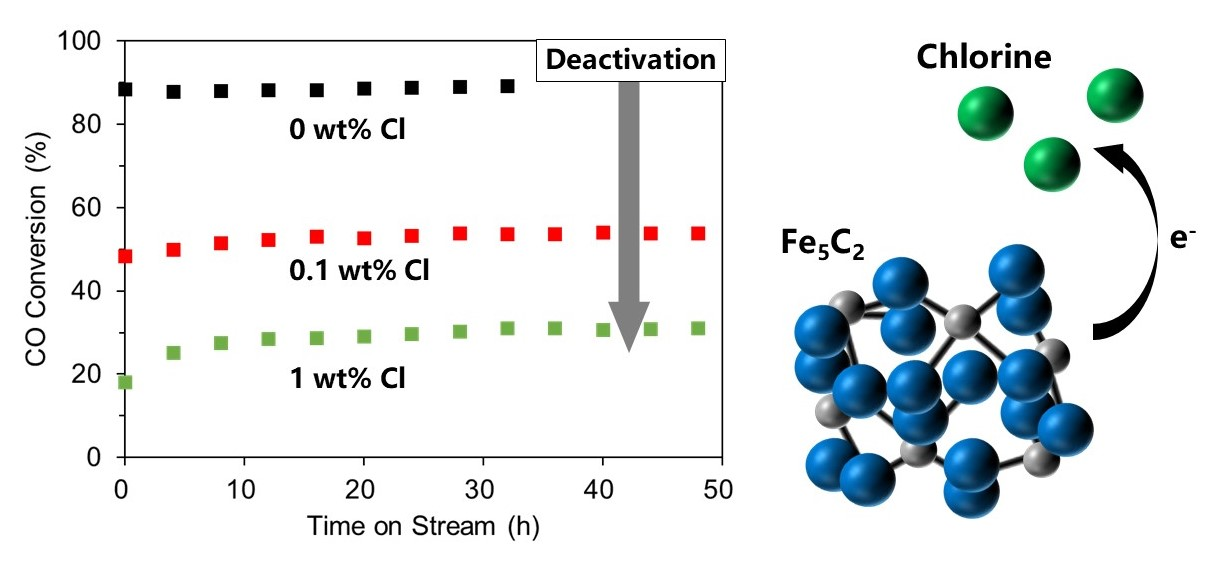
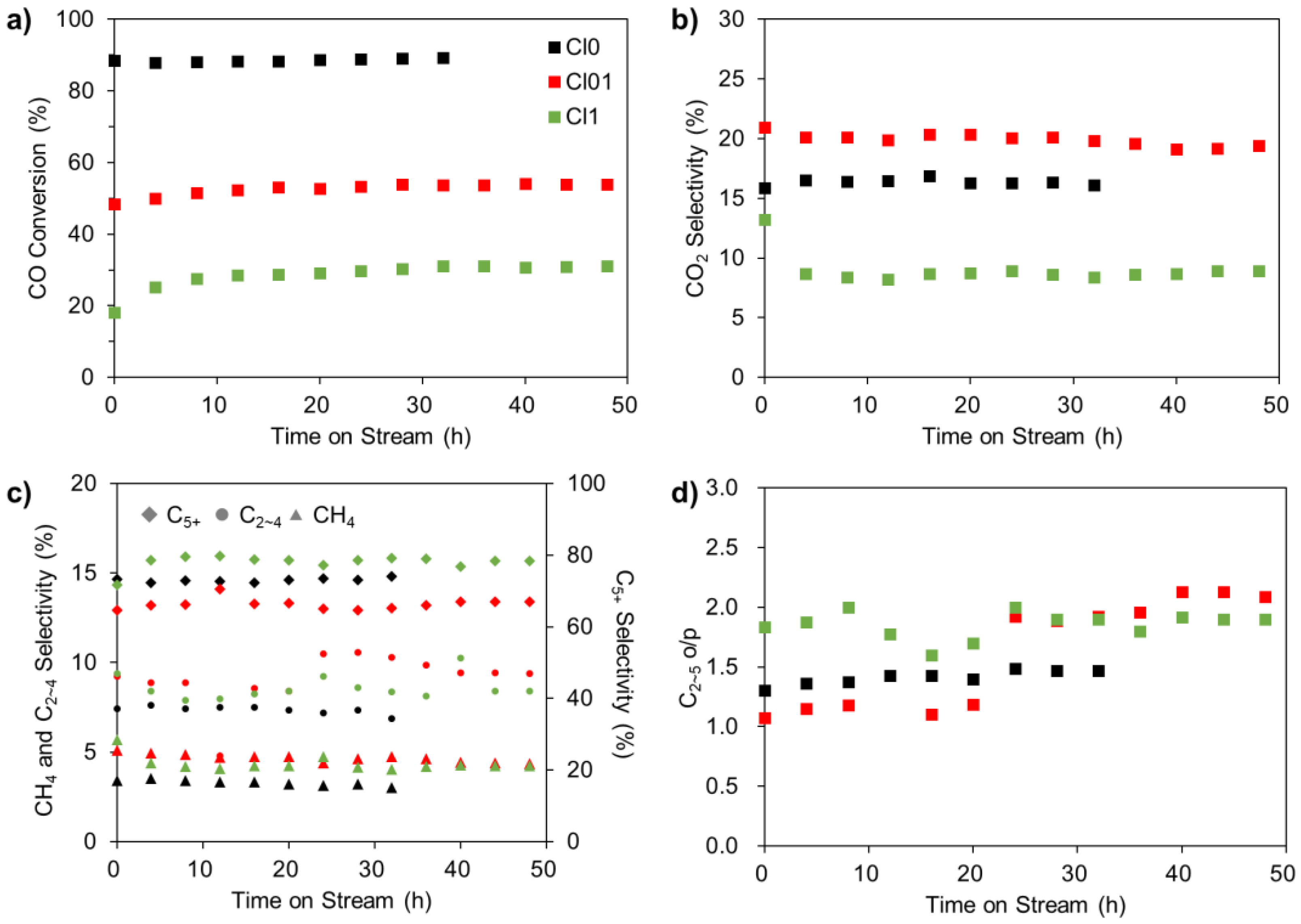
2.2. Fischer–Tropsch Synthesis Performances of the Precipitated Iron Catalysts Modified with Chlorine

The Fischer–Tropsch synthesis performances of catalysts Cl0, Cl01, and Cl1 are shown in Figure 3 and Table 2. It could be seen that the CO conversion of Cl0 was higher than that of Cl01 and Cl1. The average CO conversion of Cl0 was 89.0% whereas the average CO conversion of Cl01 and Cl1 were only 53.9% and 31.1%, respectively. This suggests that the impregnation of chlorine on the catalyst had a significant effect on the catalyst activity. Impregnating the catalyst with about 0.1 wt% chlorine caused the catalyst to lose about 40% of its activity; impregnating the catalyst with about 1 wt% chlorine caused the catalyst to lose about 65% of its activity. It is worth noting that at the initial stage of the reaction, the CO conversion of the Cl01 and Cl1 catalysts gradually increased. The CO conversion of Cl01 rose from 48.4% at 0 h to 52.3% at 12 h. The CO conversion of Cl1 rose from 18.0% at 0 h to 28.6% at 12 h. This indicated that the Cl01 and Cl1 catalysts may not have been fully activated during the reduction process.
The CO2 selectivity of Cl0, Cl01, and Cl1 first increased and then decreased with the chlorine content. The increase in the CO2 selectivity was due to an inadequate reduction of the catalyst, which led to an increase in the Fe3O4 content and promoted the water–gas shift (WGS) reaction. This was confirmed by XRD and MEMS, as shown below. However, for the Cl1 catalyst, the low activity of its Fischer–Tropsch synthesis reaction led to less water generation. The lack of reactants in the WGS reaction led to a decrease in the CO2 selectivity. According to the research of Bordoloi et al. [11], the cooperativity of trivial amounts of chlorine in the catalyst and CO2 in the feed gas will curb the hydrogen adsorption on the catalyst surface and will, therefore, increase the selectivity of the olefins. The olefin/paraffin ratio of the C2~5 products (C2~5 o/p) of Cl0, Cl01, and Cl1 followed the same trend. The C2~5 o/p of Cl0 was 1.4 whereas that of Cl01 and Cl1 were 2.2 and 1.9, respectively. This showed that chlorine inhibited the adsorption of hydrogen and increased the selectivity of the C2~5 olefins.

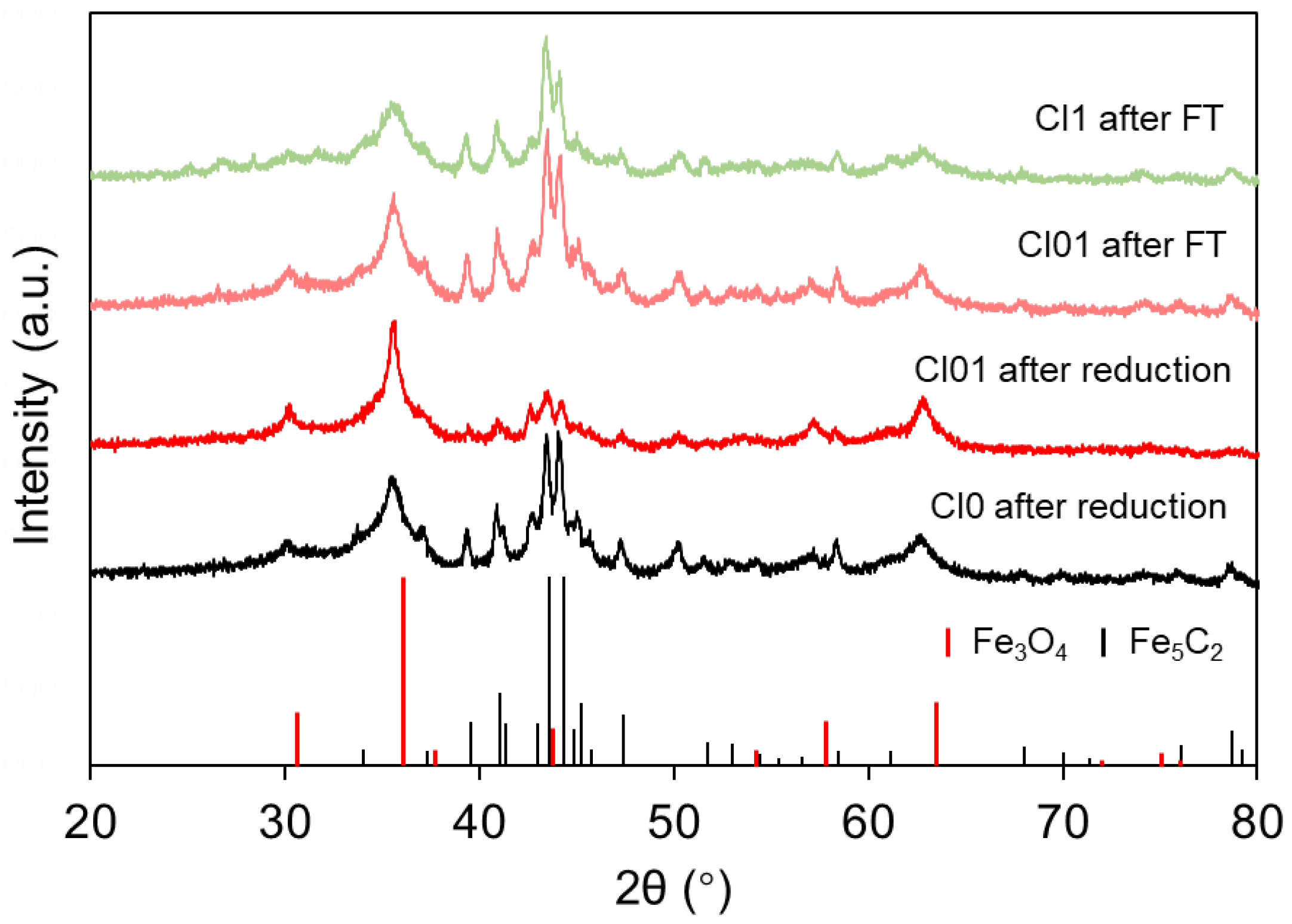
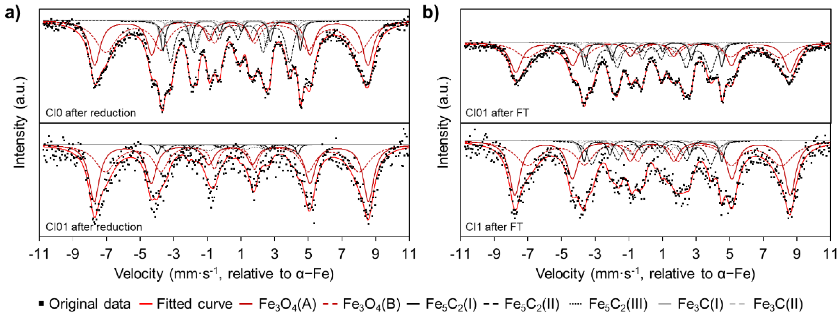
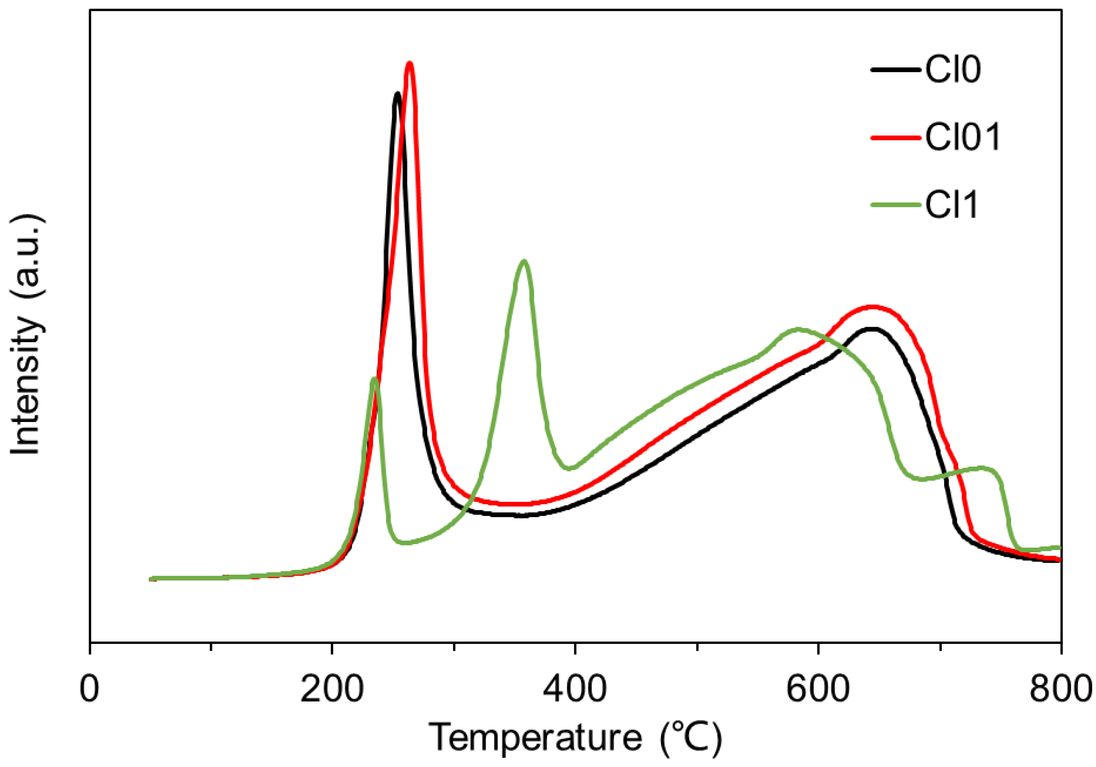
2.3. Phase Change during Fischer–Tropsch Synthesis and the Reduction Properties of the Precipitated Iron Catalysts with Chlorine

In order to determine the phase change of the precipitated iron catalysts with chlorine during Fischer–Tropsch synthesis, XRD and Mössbauer spectrum analyses were carried out on the catalyst samples after the reduction and Fischer–Tropsch synthesis reaction.
The XRD patterns of the samples are shown in Figure 4. It could be seen from the XRD patterns that all samples showed the diffraction peaks of Fe5C2 (PDF 51-0997) and Fe3O4 (PDF 75-0449). The two strong diffraction peaks at 2θ = 43.4° and 44.0° corresponded with the (021) and (510) crystal planes of Fe5C2, which are usually used in the literature to identify the Fe5C2 phase [12]. The peaks at 30.4°, 35.8°, 43.5°, 57.5°, and 67.2° corresponded with the (220), (311), (400), (511), and (440) crystal planes of Fe3O4, respectively. After the reduction, Cl0 had strong diffraction peaks of Fe5C2 and weak diffraction peaks of Fe3O4, which were similar to the XRD patterns of Cl01 after the Fischer–Tropsch synthesis reaction. At the same time, Cl01 after the reduction had weak diffraction peaks of Fe5C2 and strong diffraction peaks of Fe3O4. The differences in the XRD patterns indicated that the Cl0 catalyst was easier to reduce and carbonize during the reduction compared with Cl01. The reduction carbonization of the catalyst was impeded by chlorine impregnation. The intensity of both the Fe5C2 and Fe3O4 diffraction peaks of Cl1 after Fischer–Tropsch synthesis was lower than that of Cl01 after Fischer–Tropsch synthesis, which indicated that the Cl1 catalyst was more difficult to reduce and carbonize than the Cl01 catalyst.
The Mössbauer spectra demonstrated a similar conclusion (Figure 5 and Table S1). As can be seen in Figure 5, the Mössbauer spectrum of each sample could be fitted with seven sextets. The sextets with the 0.40~0.63 mm·s−1 IS values and 46.8~51.0 T Hhf values were ascribed to the A (tetra)/B (hexa) sites of the Fe ions in the ferrimagnetic Fe3O4 phase [1,13,14]. The sextets with the 0.28~0.40 mm·s−1 IS values and 11.5~26.0 T Hhf values corresponded with the two different Fe sites in the Fe5C2 phase [1,13,14]. The two sextets represented with a grey line with the 0.20~0.40 mm·s−1 IS values and 24.3~26.0 T Hhf values were ascribed to the Fe3C phase [1]. Quantitative calculations on the proportions of Fe3O4 and iron carbides in Cl0 after the reduction were 62.84% and 37.15%, respectively. Meanwhile, the proportions of Fe3O4 and iron carbides in Cl01 after the reduction were 89.73% and 10.28%, respectively. The existence of a remarkable amount of Fe3O4 in Cl01 after the reduction demonstrated that catalyst Cl01 could not be fully reduced even after a 24 h reduction treatment, which was consistent with the XRD results and Fischer–Tropsch synthesis performance at the initial stage. The contents of Fe3O4 and iron carbides in Cl01 after Fischer–Tropsch synthesis were 54.10% and 45.90%, respectively. In contrast, the contents of Fe3O4 and iron carbides in Cl1 after Fischer–Tropsch synthesis were 70.85% and 29.15%, respectively. The low iron carbide content in Cl1 after Fischer–Tropsch synthesis indicated that Cl1 was more difficult to reduce and carbonize, which was also consistent with the conclusions of the XRD and Fischer–Tropsch synthesis performance results.
The reduction properties of the Cl0, Cl01, and Cl1 catalysts were investigated by H2-TPR (Figure 6). The reduction peak that occurred at 190~320 °C on the TPR curves of Cl0 and Cl01 was ascribed to the reduction of CuO→Cu and Fe3O4→FeO [13,15,16,17]. The maximum value of this reduction peak of Cl01 (265.2 °C) was slightly higher than that of Cl0 (259.2 °C), which showed that under the influence of chlorine, Cl01 was more difficult to reduce than Cl0. For Cl1, the reduction of CuO→Cu and Fe3O4→FeO occurred in two phases; one occurred at 200~250 °C whereas the other occurred at 250~400 °C [13,16,18]. This indicated that the reduction of the Cl1 catalyst was more difficult than Cl0 and Cl01 due to the high chlorine content. The reduction peak at 400~730 °C on the TPR curve of Cl0 and Cl01 was classified as the reduction peak of FeO→α-Fe [15,17,18]. The reduction peak at 400~680 °C of Cl1 was ascribed to the reduction of FeO→α-Fe/FeO and the peak at 680~780 °C of Cl1 was ascribed to the reduction of Fe3O4/FeO that was stabilized by SiO2 [13]. The appearance of a reduction peak at 680~780 °C also indicated that the Cl1 catalyst was more difficult to reduce.

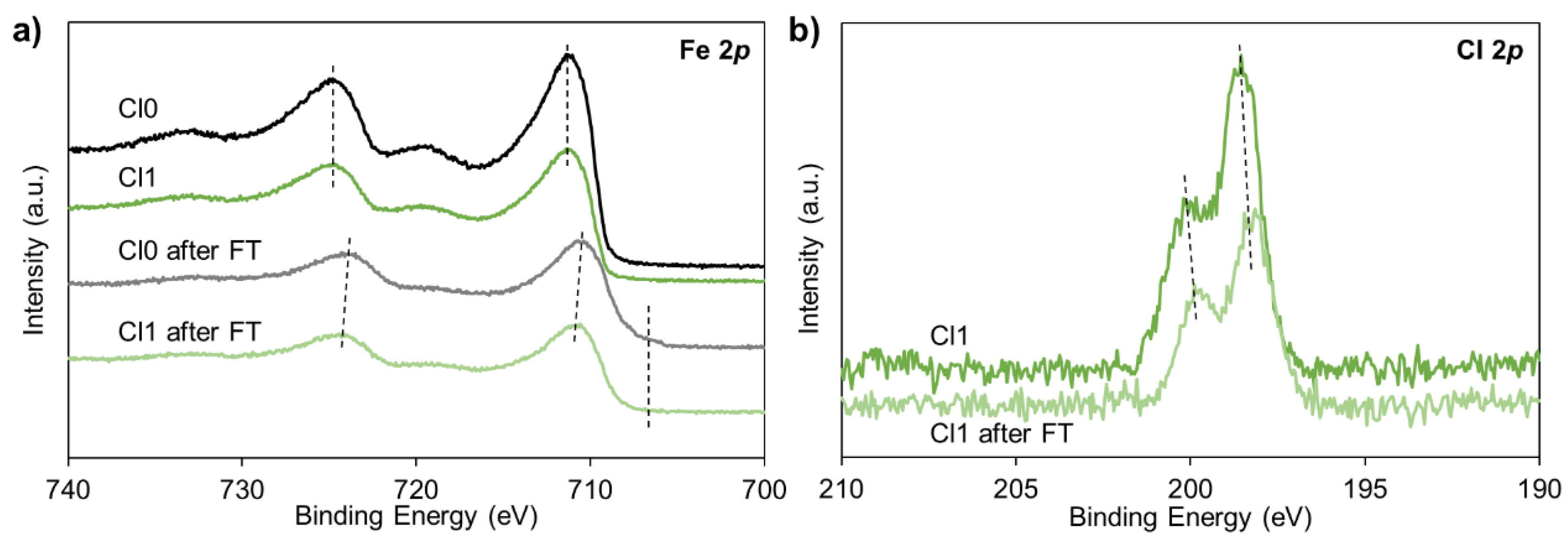
2.4. Chlorine Adsorption State of the Precipitated Iron Catalysts with Chlorine

In order to further study the mechanism of catalyst deactivation caused by chlorine, the chlorine adsorption state of the precipitated iron catalysts was investigated through XRF and XPS.
The chlorine contents on Cl01 and Cl1 after the Fischer–Tropsch synthesis reaction were measured by XRF (Table 3). The chlorine content of Cl01 and Cl1 increased slightly compared with that before the reaction. This may have been due to a small amount of iron entering the product. The chlorine content of the products was tested by ion chromatography and no chlorine was detected, indicating that the adsorption of chlorine was very strong and there was no chlorine loss in the reaction.
The Fe 2p and Cl 2p XPS spectra of Cl0 and Cl1 are shown in Figure 7; the corresponding binding energies are listed in Table S2. In Figure 7a, the peak around 710 eV corresponded with the Fe3+ binding energy of Fe 2p3/2 and the peak around 724 eV corresponded with the Fe3+ binding energy of Fe 2p1/2 [1,12,17,19]. The binding energies of Fe 2p3/2 and Fe 2p1/2 of Cl0 and Cl1 were basically the same before the Fischer–Tropsch synthesis reaction and moved to a low binding energy after the reaction, indicating that they were reduced in the reaction process. The binding energy of Fe 2p3/2 of Cl1 after the reaction was 0.31 eV higher than that of Cl0 and the binding energy of Fe 2p1/2 was 1.15 eV higher than that of Cl0, indicating that Cl1 was more difficult to reduce than Cl0. According to the literature, the XPS spectrum of Fe5C2 has characteristic peaks near 707 eV and 720 eV [1,11,12]. The signal of Cl0 after the reaction at 707 eV was significantly stronger than that of Cl1, indicating that there was more Fe5C2 on the surface of Cl0 after the reaction, which carbonized easier than Cl1 in the reaction. In Figure 7b, the two peaks were ascribed to Cl 2p3/2 and Cl 2p1/2, respectively [19,20,21]. The peaks of Cl 2p3/2 and Cl 2p1/2 of Cl1 were 198.55 eV and 200.18 eV, respectively; the values of the peaks of Cl 2p3/2 and Cl 2p1/2 of Cl1 after Fischer–Tropsch synthesis were 198.19 eV and 199.85 eV, respectively. The Cl 2p peaks of Cl1 after Fischer–Tropsch synthesis moved slightly in the direction of a low binding energy, indicating that Cl obtained electrons from Fe, making the Fe more difficult to reduce. The atomic ratio of Cl and Fe of the catalysts were also calculated based on the XPS data. The Cl/Fe ratio of Cl0, Cl1, and Cl1 after the reaction were 0.0091, 0.0823, and 0.0870, respectively. The Cl/Fe ratio of Cl1 was almost nine times as great as Cl0, which was consistent with the XRF results. The difference in the Cl/Fe ratio between Cl1 and Cl1 after the reaction was very small, which also demonstrated the strong adsorption between Cl and Fe. It could be seen from the above analysis of the XPS data that there were interactions between Cl and Fe, and Cl had a strong adsorption on the catalyst surface. This strong adsorption makes it more difficult for chlorine-containing catalysts to reduce and carbonize than non-chlorine-containing catalysts, which was consistent with the conclusions obtained by XRD, MEMS, and H2-TPR.

3. Materials and Methods

3.1. Materials

Analytical pure Fe(NO3)3·9H2O, FeCl3·6H2O, Cu(NO3)2·3H2O, Na2CO3, chemical pure K2SiO3, and liquid paraffin were purchased from Sinopharmaceuticals Reagents Co. Ltd. H2 and CO with 99.999% purity were purchased from Beijing AP BAIF Gases Industry Co., Ltd. All reagents and gases were used directly without further treatment.

3.2. Preparation and Chlorine Modification of the Precipitated Iron Catalysts

First, the precipitated iron Fischer–Tropsch synthesis catalyst was prepared based on the method reported in our previous work [17,22]. Typically, a mixture of an Fe(NO3)3·9H2O and Cu(NO3)2·3H2O aqueous solution (c(Fe3+) = 0.4 mol·L−1, c(Cu2+) = 3.5 × 10⁻³ mol·L−1) and an aqueous Na2CO3 solution (c(Na+) = 2.4 × 10⁻³ mol·L−1) were added together into a beaker by two pumps at a constant flow rate. The obtained suspension was centrifuged and washed with deionized water three times. The filter cake obtained was then pulped with a K2SiO3 solution (c(K+) = 8 mol·L−1, m(Fe):m(K2SiO3) = 1:1). The mixture was then spray-dried and calcined at 600 °C for 6 h to obtain the precipitated iron Fischer–Tropsch synthesis catalyst.
The precipitated iron Fischer–Tropsch synthesis catalysts modified with chlorine were prepared by the impregnation method. The precipitated iron Fischer–Tropsch synthesis catalysts were impregnated with an aqueous FeCl3·6H2O solution with different concentrations and dried at 120 °C overnight. Depending on the quantity of the chlorine addition, the obtained catalysts were denoted as Cl01, Cl1, and Cl5, where the numbers represented the percentage of chlorine impregnated. As a comparison, a catalyst impregnated by deionized water was also prepared, which was represented as Cl0.

3.3. Catalyst Characterization

For the samples before the reaction, the characterization was carried out directly. The samples after the reduction and reaction were stored under nitrogen after their removal from the reactor to prevent oxidation by air.
The specific surface area, pore volume, and pore distribution of all the prepared catalysts were tested by an ASAP-2020C (Micromeritics, Norcross, GA, USA) physical adsorption apparatus. All tests were carried out at liquid nitrogen temperature. Before each test, the sample was degassed at 350 °C for 3 h. The specific surface area was calculated by the BET equation. The pore volume and pore distribution were calculated using the BJH model.
X-ray fluorescence (XRF) data were collected on a ZSK Primus II X-ray fluorescence spectrometer (Rigaku, Tokyo, Japan). All samples were tableted with 20 MPa pressure before testing.
Transmission electron microscopy (TEM) images, high-angle annular dark-field scanning transmission electron microscopy (HAADF-STEM) images, and energy-dispersive X-ray (EDS) mapping images were acquired on a JEM-ARM200F transmission electron microscope (JEOL, Japan) under 200 kV.
The X-ray diffraction (XRD) experiments were carried out on a D8 Advance Powder X-ray diffractometer (Bruker, Germany) with a Cu Kα target. The tube voltage and tube current were set to 40 kV and 100 mA, respectively. The scanning range was set to 2θ = 20–80°.
The Mössbauer spectrum (MEMS) experiments were performed on an equally accelerated Mössbauer spectrometer (Wissel, Starnberg, Germany) with a 57Co radioactive source. The least square method was used to fit the spectral line. The phase of the samples was confirmed by isomer shift (IS) and hyperfine field (Hhf) measurements and the relative content was calculated by normalizing the peak area of each phase.
The H2 temperature-programmed reduction (H2-TPR) experiments were conducted on an Autochem II 2920 (Micromeritics, Norcross, GA, USA) auto-adsorption apparatus. In each test, a 100 mg sample was degassed and reduced in 50 mL/min 10 vol% H2/Ar flow. The temperature was linearly ramped from 50~900 °C at a rate of 10 °C/min. A thermal conductivity detector (TCD) was used to measure the H2 consumption.
The X-ray photoelectron spectroscopy (XPS) tests were carried out on a Thermo Escalab 250Xi system (Thermo Scientific, Waltham, MA, USA) and the base pressure was 1 × 10⁻⁹ mbar. The catalyst samples were excited with monochromatized Al Kα radiation (hν = 1486.6 eV). The analyzer was operated using a constant pass energy mode (20 eV). The C 1s peak of adventitious carbon (284.8 eV) was used as a reference for estimating the binding energy.

3.4. Fischer–Tropsch Synthesis Performance Test

The Fischer–Tropsch synthesis performance of the prepared catalysts was tested in a 1 L stirred slurry reactor manufactured by System Co. Ltd., Beijing, China. The flow diagram and a picture of the reactor are shown in Figures S1 and S2, respectively. For each test, a 10 g catalyst was dispersed in 500 mL of liquid paraffin. The catalysts were reduced using H2/CO=20 syngas at 260 °C, 2.0 MPa, and 5000 mL·g-cat−1·h−1 space velocity for 24 h. After the reduction, the reaction conditions were adjusted to 270 °C, 2.3 MPa, H2/CO=3, and 20,000 mL·g-cat−1·h−1 space velocity for the Fischer–Tropsch synthesis reaction, which was close to industrial Fischer–Tropsch synthesis reaction conditions.
The composition of the gas phase products was analyzed by an Agilent 7890B gas chromatograph. The H2, CO, and CO2 in the exhaust gas were detected by a thermal conductivity detector (TCD) and the C1~C8 hydrocarbons were detected by a flame ionization detector (FID). The CO conversion was calculated based on the CO concentration at the inlet and outlet of the reactor determined by the external standard method by Equation (1):
X ( CO ) = c ( CO ) in c ( CO ) out c ( CO ) in   .
The CH4 and CO2 selectivity were calculated based on the concentration of CH4 and CO2 at the outlet of the reactor and the amount of the converted CO by Equations (2) and (3):
S ( CH 4 ) = c ( CH 4 ) out c ( CO ) in c ( CO ) out   .
S ( CO 2 ) = c ( CO 2 ) out c ( CO ) in c ( CO ) out   .

4. Conclusions

In this work, we prepared precipitated iron Fischer–Tropsch synthesis catalysts modified with chlorine and their Fischer–Tropsch synthesis performances were tested in a 1 L stirred tank reactor under the conditions of 270 °C, 2.3 MPa, H2/CO=3, and 20,000 mL·g-cat−1·h−1 space velocity. The results showed that chlorine had a great influence on the Fischer–Tropsch synthesis performance of the precipitated iron catalyst. Compared with the catalyst without chlorine, the catalyst containing about 0.1 wt% chlorine was deactivated by about 40% and the catalyst containing about 1 wt% chlorine was deactivated by about 65%. Chlorine also led to an increase in the CO2 selectivity and olefin/paraffin ratio. XRD, Mössbauer spectra, and the H2-TPR results showed that chlorine hindered the reduction and carbonization of the catalyst and reduced the formation of active-phase Fe5C2. The results of XRF and XPS showed that there was a strong interaction between chlorine and iron; chlorine obtains electrons from iron, which was the reason why the chlorine-containing catalysts were difficult to reduce and carbonize. This work contributes to the application of iron-based catalysts in a biomass-based Fischer–Tropsch synthesis.

Supplementary Materials

The following supporting information can be downloaded at: https://www.mdpi.com/article/10.3390/catal12080812/s1, Table S1: Mössbauer spectrum fitting results of precipitated iron catalysts with chlorine after reduction and Fischer-Tropsch synthesis reaction; Table S2: Binding energy of Cl0 and Cl1 before and after Fischer-Tropsch synthesis. Figure S1: Flow diagram of the 1 L stirred tank reactor; Figure S2: Picture of the 1 L stirred tank reactor.

Author Contributions

Conceptualization, W.L.; investigation, W.L., X.Z. (Xuebing Zhang), T.W., X.Z. (Xiaoyu Zhang), and L.W.; writing—original draft, W.L.; writing—review and editing, W.L., Q.L., Y.L., and Z.M.; project administration, Q.L., Y.L., and Z.M.; funding acquisition, Q.L., Y.L., and Z.M. All authors have read and agreed to the published version of the manuscript.

Funding

This research was funded by National Key Research and Development Program (Project No. 2017YFB0602500) and the Technical Innovation project of China Energy Investment Corporation (Project No. ST930021003C).

Conflicts of Interest

The authors declare no conflict of interest. The funders had no role in the design of the study; in the collection, analyses, or interpretation of data; in the writing of the manuscript, or in the decision to publish the results.

References

  1. De Smit, E.; Weckhuysen, B.M. The renaissance of iron-based Fischer-Tropsch synthesis: On the multifaceted catalyst deactivation behaviour. Chem. Soc. Rev. 2008, 37, 2758–2781. [Google Scholar] [CrossRef] [PubMed]
  2. Liu, Z.; Li, Y.; Zhou, J.; Zhang, B. Deactivation model of Fischer-Tropsch synthesis over an Fe-Cu-K commercial catalyst. Appl. Catal. A Gen. 1997, 161, 137–151. [Google Scholar] [CrossRef]
  3. Ma, W.; Jacobs, G.; Sparks, D.E.; Pendyala, V.R.R.; Hopps, S.G.; Thomas, G.A.; Hamdeh, H.H.; MacLennan, A.; Hu, Y.; Davis, B.H. Fischer–Tropsch synthesis: Effect of ammonia in syngas on the Fischer–Tropsch synthesis performance of a precipitated iron catalyst. J. Catal. 2015, 326, 149–160. [Google Scholar] [CrossRef] [Green Version]
  4. Ma, W.; Jacobs, G.; Sparks, D.E.; Shafer, W.D.; Hamdeh, H.H.; Hopps, S.D.; Pendyala, V.R.R.; Hu, Y.; Xiao, Q.; Davis, B.H. Effect of H2S in syngas on the Fischer–Tropsch synthesis performance of a precipitated iron catalyst. Appl. Catal. A Gen. 2016, 513, 127–137. [Google Scholar] [CrossRef] [Green Version]
  5. Tijmensen, M.; Faaij, A.; Hamelinck, C.N.; Hardeveld, M. Exploration of the possibilities for production of Fischer Tropsch liquids and power via biomass gasification. Biomass Bioenergy 2002, 23, 129–152. [Google Scholar] [CrossRef]
  6. Hamelinck, C.N.; Faaij, A.P.C.; Uil, H.D.; Boerrigter, H. Production of FT transportation fuels from biomass; technical options, process analysis and optimisation, and development potential. Energy 2004, 29, 1743–1771. [Google Scholar] [CrossRef]
  7. Steen, E.V.; Claeys, M. Fischer-Tropsch Catalysts for the Biomass-to-Liquid (BTL)-Process. Chem. Eng. Technol. 2010, 31, 655–666. [Google Scholar] [CrossRef]
  8. Ma, W.; Jacobs, G.; Kang, J.; Sparks, D.E.; Davis, B.H. Fischer–Tropsch synthesis. Effect of alkali, bicarbonate and chloride addition on activity and selectivity. Catal. Today 2013, 215, 73–79. [Google Scholar] [CrossRef]
  9. Ma, W.; Jacobs, G.; Thomas, G.A.; Shafer, W.D.; Sparks, D.E.; Hamdeh, H.H.; Davis, B.H. Fischer–Tropsch Synthesis: Effects of Hydrohalic Acids in Syngas on a Precipitated Iron Catalyst. ACS Catal. 2015, 5, 3124–3136. [Google Scholar] [CrossRef]
  10. Pendyala, V.R.R.; Jacobs, G.; Ma, W.; Sparks, D.E.; Shafer, W.D.; Khalid, S.; Xiao, Q.; Hu, Y.; Davis, B.H. Fischer–Tropsch Synthesis: XANES Investigation of Hydrogen Chloride Poisoned Iron and Cobalt-Based Catalysts at the K-Edges of Cl, Fe, and Co. Catal. Lett. 2016, 146, 1858–1866. [Google Scholar] [CrossRef]
  11. Ghosh, I.K.; Iqbal, Z.; van Heerden, T.; van Steen, E.; Bordoloi, A. Insights into the unusual role of chlorine in product selectivity for direct hydrogenation of CO/CO2 to short-chain olefins. Chem. Eng. J. 2021, 413, 127424. [Google Scholar] [CrossRef]
  12. Yang, C.; Zhao, H.; Hou, Y.; Ma, D. Fe5C2 Nanoparticles: A Facile Bromide-Induced Synthesis and as an Active Phase for Fischer–Tropsch Synthesis. J. Am. Chem. Soc. 2012, 134, 15814–15821. [Google Scholar] [CrossRef] [PubMed]
  13. Hou, W.; Wu, B.; Yang, Y.; Hao, Q.; Tian, L.; Xiang, H.; Li, Y. Effect of SiO2 content on iron-based catalysts for slurry Fischer–Tropsch synthesis. Fuel Process. Technol. 2008, 89, 284–291. [Google Scholar] [CrossRef]
  14. Suo, H.; Wang, S.; Zhang, C.; Jian, X.; Wu, B.; Yong, Y.; Xiang, H.; Li, Y.W. Chemical and structural effects of silica in iron-based Fischer–Tropsch synthesis catalysts. J. Catal. 2012, 286, 111–123. [Google Scholar] [CrossRef]
  15. Wu, B.; Tian, L.; Bai, L.; Zhang, Z.; Xiang, H.; Li, Y.W. Study on a new iron catalyst for slurry Fischer–Tropsch synthesis. Catal. Commun. 2004, 5, 253–257. [Google Scholar] [CrossRef]
  16. Chun, D.H.; Rhim, G.B.; Youn, M.H.; Deviana, D.; Lee, J.E.; Park, J.C.; Jeong, H. Brief Review of Precipitated Iron-Based Catalysts for Low-Temperature Fischer–Tropsch Synthesis. Top. Catal. 2020, 63, 793–809. [Google Scholar] [CrossRef]
  17. Lin, Q.; Cheng, M.; Zhang, K.; Li, W.; Wu, P.; Chang, H.; Lv, Y.; Men, Z. Development of an Iron-Based Fischer—Tropsch Catalyst with High Attrition Resistance and Stability for Industrial Application. Catalysts 2021, 11, 908. [Google Scholar] [CrossRef]
  18. Chang, H.; Cheng, M.; Lin, Q.; Zhu, J.; Lv, Y.; Men, Z. Effects of binder addition process parameters on physical-chemical and catalytic performance of iron-based Fischer-Tropsch (F-T) synthesis catalyst. J. China Coal Soc. 2021, 46, 7. [Google Scholar]
  19. Kim, Y.J.; Park, C.R. Analysis of Problematic Complexing Behavior of Ferric Chloride with N,N-Dimethylformamide Using Combined Techniques of FT-IR, XPS, and TGA/DTG. Inorg. Chem. 2002, 41, 6211–6216. [Google Scholar] [CrossRef]
  20. Kishi, K.; Ikeda, S. X-ray photoelectron spectroscopic study of the reaction of evaporated metal films with chlorine gas. J. Phys. Chem. 1974, 78, 754–758. [Google Scholar] [CrossRef]
  21. González-Carballo, J.M.; Pérez-Alonso, F.J.; García-García, F.J.; Ojeda, M.; Fierro, J.L.G.; Rojas, S. In-situ study of the promotional effect of chlorine on the Fischer–Tropsch synthesis with Ru/Al2O3. J. Catal. 2015, 332, 177–186. [Google Scholar] [CrossRef]
  22. Li, H.; Liu, Z.; Li, W.; Lv, Y.; Ma, Z.; Men, Z.; Yan, Z. Deactivation behavior investigation on commercial precipitated iron Fischer–Tropsch catalyst for long time reaction. J. Porous Mater. 2021, 29, 307–315. [Google Scholar] [CrossRef]
Figure 1. (a) TEM image, (b) HAADF-STEM image, and (cg) STEM-EDS mapping images of freshly prepared Cl1 catalyst; (c) is the superposition of all element images and (dg) correspond with the mapping images of (d) Fe, (e) O, (f) Si, and (g) Cl.
Catalysts 12 00812 g001
Figure 2. XRD patterns of freshly prepared precipitated iron catalysts with chlorine.
Catalysts 12 00812 g002
Figure 3. (a) CO conversion, (b) CO2 selectivity, (c) hydrocarbon product selectivity, and (d) C2~5 o/p value versus time on stream over Cl0, Cl01, and Cl1 catalyst.
Catalysts 12 00812 g003
Figure 4. XRD patterns of Cl0, Cl01, and Cl1 catalysts after reduction and Fischer–Tropsch synthesis reaction.
Catalysts 12 00812 g004
Figure 5. Mössbauer spectra of precipitated iron catalysts with chlorine after (a) reduction and (b) Fischer–Tropsch synthesis reaction.
Catalysts 12 00812 g005
Figure 6. H2-TPR profiles of Cl0, Cl01, and Cl1 catalysts.
Catalysts 12 00812 g006
Figure 7. XPS spectra of Cl0 and Cl1 catalysts; (a) are spectra of Fe 2p and (b) are spectra of Cl 2p.
Catalysts 12 00812 g007
Table 1. Composition, specific surface area, pore volume, and average pore size of freshly prepared precipitated iron catalysts.
CatalystFe2O3:Cu:K:SiO2:Cl 1Specific Surface Area (m2·g−1)Pore Volume (cm3·g−1)Average Pore Size (nm)
Cl0100:3.55:1.90:10.28:0.08140.80.5112.1
Cl01100:3.76:2.04:11.33:0.14140.60.5212.0
Cl1100:3.53:1.85:10.33:1.00134.40.5012.2
Cl5100:3.55:1.41:10.71:4.02123.00.4812.6
1 Mass ratio.
Table 2. Fischer–Tropsch synthesis performance of precipitated iron catalysts 1.
CatalystCO Conversion (%)Selectivity (%)
CO2CH4C2~4C2~5 o/p 2C5+
Cl089.016.43.27.31.473.1
Cl0153.919.44.59.72.266.4
Cl131.18.74.28.71.978.4
1 All catalysts were tested at 270 °C, 2.3 MPa H2/CO=3 syngas, and 20,000 mL·g-cat−1·h−1 space velocity. CO conversion and selectivities were calculated using the average of the previous 20 h. 2 Molar ratio.
Table 3. Chlorine content of Cl01 and Cl1 before and after Fischer–Tropsch synthesis reaction.
CatalystFe2O3:Cl Before Reaction 1Fe2O3:Cl After Reaction 1
Cl01100:0.14100:0.19
Cl1100:1.00100:1.09
1 Mass ratio.
Publisher’s Note: MDPI stays neutral with regard to jurisdictional claims in published maps and institutional affiliations.

