Article

In Situ Removal of Benzene as a Biomass Tar Model Compound Employing Hematite Oxygen Carrier

1
Guangzhou Institute of Energy Conversion, Chinese Academy of Sciences, Guangzhou 510640, China
2
School of Energy and Power Engineering, Northeast Electric Power University, No. 169 Changchun Road, Chuanying District, Jilin City 132012, China
3
College of Chemistry and Bioengineering, Guilin University of Technology, Guilin 541004, China
4
Southern Marine Science and Engineering Guangdong Laboratory (Guangzhou), No. 1119 Haibin Road, Nansha Street, Nansha District, Guangzhou 511458, China
*
Author to whom correspondence should be addressed.
Catalysts 2022, 12(10), 1088; https://doi.org/10.3390/catal12101088
Submission received: 17 August 2022 / Revised: 14 September 2022 / Accepted: 16 September 2022 / Published: 21 September 2022

Abstract

:
Tar is an unavoidable biomass gasification byproduct. Tar formation reduces gasification efficiency and limits the further application of biomass gasification technology. Hence, efficient tar removal is a major problem to be solved in the formation and application of biomass gasification technology. Chemical looping gasification (CLG), a novel and promising gasification technology has attracted extensive attention owing to its low tar generation. Active oxygen carriers (OCs), the reduced OC in CLG, are considered to be excellent catalysts for tar cracking. In this study, the use of benzene as a typical tar model compound for tar removal using the iron ore OC is investigated. In the blank experiment, where an inert material (SiO2) is used as the carrier, the benzene cracking is relatively low, and the benzene conversion, H2 yield, and carbon conversion are 53.65%, 6.33%, and 1.24%, respectively. The addition of hematite promotes benzene cracking. A large amount of oxygen-containing gases (CO and CO2) are generated. Additionally, the conversion degrees for benzene, H2 and carbon are about 67.75%, 21.55%, and 38.39%, respectively. These results indicate that hematite performs both oxidation and catalysis during benzene cracking. The extension of the residence time facilitates benzene removal, owing to the good interaction between the gas phase and solid phase. The addition of water vapor inhibits the benzene conversion and promotes the conversion of carbon deposition. The lattice oxygen reactivity of hematite OC shows an uptrend as the cycle number is increased during the benzene conversion cycle. The experimental results confirm that CLG has a low-tar advantage and that hematite is an effective OC for benzene removal.

1. Introduction

China’s renewable energy source is equivalent to 2.15 billion standard coal, of which over 50% is biomass energy, which is two times as powerful as hydro energy and three and a half times as powerful as wind energy [1]. Biomass offers a significant advantage over fossil fuels in terms of CO2 emission reduction. For instance, the CO2 emissions of a biomass-fired plant with a capacity of 25,000 kW are 220 thousand tons less than that of a coal-fired plant. Additionally, biomass is a low-sulfur, low-nitrogen, and low-ash energy source with reduced environmental pollution levels during utilization [2,3]. Owing to the many similarities between biomass and fossil fuel, including molecular structure and utilization route, the industrial system of fossil fuel can be used for biomass conversion with minor adjustments, generating solid, liquid, and gas fuel or industrial raw materials. With the goal of carbon neutrality, it is crucial to advance biomass energy technology.
One of the practical technologies for biomass utilization is gasification, which converts biomass to syngas via thermo-chemical conversion [4]. Syngas mainly includes CO and H2, which can be used to generate heat and power and as a platform compound for the synthesis of liquid fuels and chemicals [5,6,7]. Biomass gasification has several advantages including high efficiency, low emissions, and simplicity of integration [8]. However, a significant drawback of the conventional gasification process is the high cost of oxygen sources. During gasification, solid fuel is partially oxidized, and air, oxygen, and H2O steam are commonly used as gasified agents [9]. Using air as a gasification medium will result in the low heating value of the gas products because of nitrogen dilution [10]; using oxygen is beneficial for obtaining high heating-value gas products, but the high cost of oxygen separation cannot be ignored [11]; producing H2O steam requires an external boiler, which consumes a lot of energy [12,13]. Additionally, tar, which accounts for 5%~15% of total energy in raw biomass, is a byproduct of gasification [14]. Therefore, it is crucial to design a biomass gasification method that has a low-cost oxygen source, produces less tar, and produces high-heating-value gas products.
Chemical looping gasification (CLG) is an effective solution for the abovementioned biomass gasification technology demand [15,16,17]. As shown in Figure 1, typical gasification is decomposed into two steps in CLG. In the fuel reactor (FR), the metal oxide is used as the oxygen carrier (OC) [18,19,20,21,22,23,24,25], which serves the dual purpose of oxidation and catalysis in the gasification [26]. The OC catalyzes to facilitate biomass gasification as well as a lattice oxygen source to replace molecular oxygen. After reacting with biomass, the OC is reduced, and it is then sent to the air reactor for air calcining to regenerate. Thereafter, the OC reenters the FR and AR cycle, as well as creating a reduction and oxidation loop (chemical looping). CLG does not require high-cost production of pure oxygen or water steam, and the regulation of syngas components can be achieved by introducing CO2/H2O. Additionally, the OC effectively promotes tar conversion, which is a great advantage for the thermo-chemical conversion of highly volatile solid fuels such as biomass.
Biomass tar is a complex mixture, which consists of several polycyclic organic compounds. The major compositions of biomass tar are presented in Table 1. Benzene accounts for the highest proportion of tar compositions, and the majority of other compositions are benzene derivatives [27]. The benzene ring is common to see in the molecular structure of tar compounds, and this phenomenon might be attributed to the extreme stability of the benzene ring [28,29]. Both benzene and naphthalene barely decompose below 900 °C, and their decompositions are not significant until 1000 °C. Moreover, the thermal stability of benzene is higher than that of naphthalene [30]. According to certain studies, naphthalene must undergo a complete breakdown at a reaction temperature higher than 1300 °C, while benzene must undergo a complete decomposition at a reaction temperature higher than 1400 °C [31]. It can be inferred that the decomposition of benzene is a key barrier to the complete conversion of biomass tar because benzene is present in large amounts and has nearly the highest thermal stability. Currently, several methods have been suggested for benzene elimination in gasification. These methods include catalytic steam reforming [32,33], photothermal steam reforming [34], steam-oxygen gasification [35,36], microwave-based treatment [37], and plasma technology [38,39]. Only a few studies in the literature report the in situ removal of benzene in CLG.
To investigate the effect of CLG operation on the tar conversion, benzene was used as the biomass tar model compound in the CLG experiments to simulate the in situ removal of biomass tar decomposition using a fixed bed reactor, and hematite was employed as the OC. The effects of residence time, steam/carbon ratio, and cycle number on benzene conversion were investigated. The results provide some important references for biomass tar elimination in CLG operation.

2. Results and Discussion

2.1. Benzene Conversion Characteristics Using Hematite

The characteristics of benzene cracking between inert SiO2 and hematite were compared to highlight the role of iron ore OC, as shown in Figure 2 and Table 2, Table 3, Table 4 and Table 5. The hematite mass, benzene flow, and N2 flow were set as 0.5 g, 40 mL/min, and 0.05 mL/min, respectively. The total reaction time was 60 min, and each point was collected every 3 min using a sampling bag.
In the blank experiment (using SiO2), the gas concentrations were low, the main gas component was H2 (95.40%) and the CH4 (3.91%) and C2Hm (0.69%) contents were low. The oxygenated gases (CO and CO2) were not observed. H2 concentration increased gradually in the first 30 min before stabilizing. Additionally, the benzene conversion, H2 yield, and carbon deposition were 55.37%, 7.22%, and 1.98%, respectively. These results indicate that the self-cracking performance of benzene at high temperatures was low, since the inert SiO2 carrier had no oxidation and catalysis ability. During this process, the reaction (R1) played a major role [41]. Although the benzene conversion was 55.37%, the majority of benzene only partially cracked and only a small portion of its C-H/C-C bonds was completely broken. Thus, the H2 yield (gas product) and carbon deposition (solid product) were very low, and a large amount of benzene series (liquid product) was generated, as shown in (R2). Benzene dehydrogenation mostly generates benzene radicals, which later combine with other radicals to form a new, larger benzene series. The mass of the generated liquid products was 1.20 g and the main component (biphenyl) accounted for 75.83% of that mass.
However, hematite addition accelerated the benzene cracking. Along with the H2, CH4, and C2Hm, a large amount of oxygen-containing gases (CO and CO2) was generated. In the initial stage, a small amount of absorbed oxygen reacted with the benzene on the surface of the hematite, which leads to the formation of CO and CO2. After 25 min, the CO concentration increased and reached its peak at 33 min, indicating that lattice oxygen was involved in the benzene oxidation. In the final stage, lattice oxygen was absent, making it impossible to meet the oxygen demand of benzene oxidation, but part of the OC was reduced to metal Fe, which catalyzed the benzene cracking. Therefore, CO concentration declined gradually, and the H2 concentration increased continuously.
Furthermore, compared to the blank experiment, the benzene conversion, H2 yield and carbon deposition increased to 69.05%, 21.96%, and 39.13%, respectively. Hematite has the dual function of oxidation and catalysis. First, benzene underwent an oxidation-reduction reaction with hematite to generate a large amount of oxygen-containing gas, while the hematite was reduced to metallic Fe or Fe3C, as shown in (R3). Subsequently, the generated Fe or Fe3C acted as a catalyst to catalytically crack the benzene, and large amounts of hydrogen and carbon deposits were generated, as shown in (R4). Additionally, when compared to the blank experiment, 0.55 g of liquid products were generated during the process. This was attributed to the relatively low oxidation and catalytic ability of hematite. Thus, the secondary reaction R5 occurred in the process.
C6H6 → Gas (H2/CH4/C2Hm) + Liquid (CxHy, x > 4) + Solid (C) ∆H > 0
Catalysts 12 01088 i001H > 0
C6H6 + Fe2O3 → H2/CH4/CO/CO2/C2Hm + Fe/Fe3C  ∆H > 0
C 6 H 6 Fe / Fe 3 C Gas   ( H 2 / CH 4 / C 2 H m ) + Liquid   ( C x H y ( x > 4 ) ) + Solid   ( C )   H   >   0  

2.2. The Residence Time

This section investigates the effect of residence time on benzene cracking, and the result is shown in Figure 3. The hematite mass and benzene flow were set as 0.5 g and 0.05 mL/min, respectively. The total reaction time was 60 min. The residence time was adjusted by controlling the N2 flow(40, 60, 80, 100 mL/min).
The benzene conversion degree increased from 63.5% to 78.3% when the residence time increased from 0.032 to 0.08 s. Over 0.053 s, the benzene conversion increased from 78.3% to 81.1%, but at a slower rate. There was a significant positive correlation between the benzene conversion degree and the residence time. Long residence time allows for increased interaction between benzene and hematite, which is beneficial for benzene cracking. The increased conversion degree reduced slightly after 0.053 s, because the benzene-cracking capacity of the OC was close to the saturation at this condition. Carbon deposition and H2 are the typical byproducts of benzene cracking (R1), and their percentage–time curves were similar to that of the benzene conversion degree. The difference was in the period of 0.032 to 0.053 s, which showed a rapid increase in the carbon deposition and H2 yield curves. The restricted amount of lattice oxygen capacity made it increasingly difficult to completely oxidize input benzene. Therefore, there was a rapid increase in both carbon deposition and H2 yield.
The main gas components were H2 and CO. A small amount of CH4 and CO2 was observed when the residence time was above 0.04 s. Over the residence time, the H2 concentration increased from 12.5% to 31.9%, and the CO concentration increased from 1.9% to 4.4%. As the residence time increased, the lattice oxygen was depleted, and the reducing gas content increased. For the benzene cracking process, OC plays a dual role in catalysis and oxidation in the range of 0.04 to 0.053 s, but the oxidation function declines after 0.053 s because lattice oxygen was exhausted, and the reducing gas content subsequently increased.

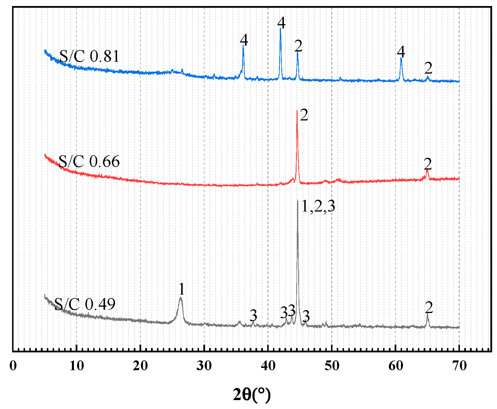
2.3. H2O Steam Content

H2O steam is usually used as a gasifying agent to promote biomass gasification. The effect of H2O steam on benzene conversion degree, H2 yield, and carbon deposition was investigated, and the Steam/Carbon ratio (S/C) was set in a range of 0.49–1.14. The results are presented in Figure 4. The hematite mass, benzene flow, and N2 flow were set as 0.5 g, 60 mL/min, and 0.03 mL/min, respectively. The total reaction time was 60 min. The residual solid products were analyzed by X-ray diffraction (XRD, X’Pert Pro MPD) and Cu Kα radiation (λ = 0.1504 nm) at a voltage of 40 kV and a current of 40 mA. The scanning rate was 2°/min from 2θ = 5° to 80° at a step of 0.02°.
H2O steam inhibited the benzene decomposition, and the benzene conversion degree reduced from 81.8% to 66.8% when the S/C value increased from 0.49 to 1.14. According to (R1)~(R4), benzene was decomposed with the release of H2, as well as carbon deposition. As the benzene conversion degree decreased, H2 yield reduced from 55.5% to 3.7%, while carbon deposition reduced from 35.7% to 0.33%.
There were two possible reasons for the H2O inhabitation of the benzene decomposition. First, in our experimental devices, liquid H2O was pumped into the reactor where it was gasified to H2O steam because of the high internal temperature. The H2O gasification had a significant impact on the gas flow in the reactor, resulting in a higher flow through the quartz tube. Consequently, the residence time of benzene and its decomposition products was shortened leading to a decrease in the benzene conversion degree. Second, the introduction of H2O steam enhanced the oxidation performance of the atmosphere, leading to OC reduction. Thereafter, the catalysis effect, which was dependent on the reduced OC, diminished as a result of the reduced OC formation.
C/Fe3C + H2O → CO/CO2 + H2 + Fe ∆H > 0
Figure 5 shows the variation in the XRD pattern of the reduced OC when the S/C value increased from 0.49 to 0.81. When the S/C value was set at 0.49, the reduced OC primarily contained metal Fe, carbon, and Fe3C. Carbon and Fe3C vanished as the S/C value was increased to 0.66. Metal Fe was the dominant phase, and its signal intensity was reduced relative to that of the S/C value of 0.49. When the S/C value was increased to 0.81, the signal intensity of metal Fe decreased further, and FeO1−δ was observed in the spectrum. The above phenomenon indicated that H2O first reacted with carbon deposition and Fe3C before oxidizing into FeO1−δ when the carbon was used up. Upon the metal Fe oxidation, the catalysis effect of the OC decreased, resulting in a lower benzene conversion degree. Therefore, the S/C should be set at a level that allows for sufficient elimination for carbon deposition, and little oxidation to the reduced OC, at the same time. When the S/C value reached 0.66, the Fe3C pattern was too weak to be observed, and the OC maintained an almost completed reduced state. Therefore, the S/C value was set at 0.66 for the cyclic experiments.
Figure 6a–c shows the morphology of the OC at different stages. Figure 6a depicts the morphology of the original OC. There were massive blocks distributed in the picture with a few small blocks adhering to the surface. These blocks were made up specifically of the reduced OC particle. After reacting with benzene, the OC particle agglomerated into blocks with a smooth edge, and some tubes, overlapping on the surface of the blocks, crossed over with each other, as shown in Figure 6b. These microtubes had distinct structures from the OC blocks. According to the fixed bed experiments, a large amount of carbon deposition was found in the reduced OC, and these microtubes could be formed from the carbon nanotube polymer, which was generated during the carbon deposition ((R1) and (R4)). Similar results were found in the literature [42]. The carbon microtubes disappeared when H2O steam was introduced into the reaction (R5). Carbon deposition was converted to CO/CO2 when it reacted with H2O. Figure 6c depicted the morphology of the microtube-free OC. After reacting to H2O steam, the OC structure became loose and irregular, and the carbon microtubes were not observed in the image.

2.4. The Cycle Numbers

Figure 7 shows the variations in benzene conversion during 5 chemical looping redox cycles. In the benzene conversion stage, the hematite mass, S/C, benzene flow, and N2 flow were set as 0.5 g, 0.66, 60 mL/min, and 0.03 mL/min, respectively. The total reaction time was 60 min. In the oxidation stage, the air flow was set as 300 mL/min for 30 min.
The benzene conversion degree increased from 63.9% to 74.4% as the cycle number increased. The H2 yield increased from 13.4% to 43.2%, and the carbon deposition increased from 5.8% to 31.0%. This improvement was attributed to the increase in the catalytic effect of OC, which could be observed in the H2 yield and carbon deposition figures.
The multiple cycles were divided into two stages. In stage I, rapid increases in H2 yield and carbon deposition were observed in the 2nd cycle. The H2 yield and carbon deposition of the 2nd cycle were more than twice those of the 1st cycle. However, compared to that of the 2nd cycle, the benzene conversion degree of the 1st cycle only increased by about 10%. The benzene conversion could not have increased at the same time that H2 yield and carbon deposition were increasing so rapidly. It ought to be related to the further decomposition of medium products generated from the benzene cracking. According to Section 3.3, it could be inferred that the OC was almost reduced to metal Fe. A serious agglomeration would happen to the OC after reduction, resulting in the deactivation of the OC. Lattice oxygen could not be recovered as completely as in the original, and a part of low-valence Fe oxides was exposed to benzene, improving the catalytic effect of the OC. Consequently, the medium products generated from the benzene cracking could be further decomposed by such an OC, leading to a higher H2 yield and a higher carbon deposition. In stage II, the primary effect was eliminated during stage I, and the OC performance was stable. The catalytic effect of the OC gradually increased as the cycle number increased, and the benzene conversion degree also increased.
Figure 8 shows the influence of cycle number on relative concentration of gas products and H2/CO ratio. As the cycle number increased from 1 to 4, the H2 concentration increased from 56.6% to 61.2%, and the CO and CO2 concentration decreased from 38.8% to 35.5% and from 4.4% to 3%, respectively. This variation in gas-product relative concentration indicated that the lattice oxygen gradually deactivated after multiple redox cycles. The oxidative performance of the OC was declined, while the catalytic performance was improved. Therefore, the H2 yield, carbon deposition, and H2/CO ratio all increased after multiple redox cycles.

3. Materials and Methods

3.1. Hematite

In the experiments, Australian hematite was used as the OC, and its compositions are listed in Table 5. The hematite was heated from room temperature to 1100 ℃ at a heating rate of 10 ℃/min before being maintained at 1100 ℃ for 3 h. Thereafter, the hematite was naturally cooled to room temperature before being ground into a powder and sieved to a diameter less than 0.15 mm.

3.2. Fixed Bed Experiment

The fixed bed reactor is shown in Figure 9. Benzene or deionized water was injected into the valve by using a high-pressure infusion pump at a certain flow rate and a pressure of 1 atm, and the N2 or air flow was controlled by using a mass flowmeter. The quartz tube had an outer diameter of 20 mm, and inner diameter of 15 mm, and a length of 800 mm. In the middle of the quartz tube, there was a porous bezel, which carried a certain mass of quartz cotton (about 0.02 g), and the OC was placed on top of it. To avoid condensation of liquid products, a heater (150 °C) was wrapped around the line connecting the quartz tube to the gas collector and the bottom of the quartz tube, which was placed at the center of the reactor. The reaction temperature was set as 850 °C. The exit of the reactor was connected to a gas collector, which contained isopropanol. After the collection, the solution in the collector was stored at 5 °C. The gas product was collected in the sample bag for subsequent analysis. After the benzene conversion experiment, air was used to oxidize the carrier and to eliminate the carbon deposit, and the gas product was collected by using the sample bag. The amount of carbon deposit from the benzene conversion was calculated by measuring the CO and CO2 content in the gas product. The solution in the collector was transferred to a 200 mL volumetric flask. The gas and liquid products were analyzed using the Agilent 7890A gas chromatograph; the split flow was set as 10:1, the FID detector was set at 280 °C, the DB-5HT nonpolar capillary column was equipped with gas chromatograph, and the column was heated from 40 °C to 280 °C at a heating rate of 40 ℃/min.

3.3. Data Processing

During the experiment, isopropanol was used to absorb the content of benzene (g/L) as part of the non-participating reaction, and the conversion degree of benzene was:
η t = m t m 0 m t × 100 %
In the formula:
mt--------Amount of benzene fed during reaction time (g);
m0-------Quality of unreacted benzene (g).
The total accumulation of gas exports was calculated using the nitrogen balance. The formula was shown in (2).
V o u t = V i n V n
In the formula:
Vin--------Total volume of imported nitrogen (L);
Vout-------Total volume of gas outlet (L);
Vn-------The volume fraction of the total volume of the outlet occupied by N2 in the dry-base state.
Carbon deposition Yc(%):
Y c ( % ) = 12 m c 13 ( m i m 0 ) × 100 %
In the formula:
mi--------Amount of benzene fed during reaction time (g);
m0-------Quality of unreacted benzene (g);
mc-------Carbon mass on the surface of the OC (g), which was calculated by measuring the CO and CO2 content during the OC oxidation.
H2 yield is calculated as follows:
Y H 2 ( % ) = 2 [ H 2 ] 6 [ n ] i n + 2 [ m ] i n × 100 %
In the formula:
[n]--------The number of moles of imported benzene;
[m]--------The number of moles in imported H2O.
Steam/carbon (S/C) is the mass flow ratio of H2O steam to benzene carbon:
S / C = q m ,   H 2 O q m ,   b e n e z e n e   c a r b o n × 100 %
In the formula:
q m ,   H 2 O --------The mass flow of H2O steam (g/min);
q m ,   b e n e z e n e   c a r b o n -------The mass flow of carbon of benzene (g/min).
The relative concentrations of gas products are obtained as follows:
R e l a t i v e   c o n c e n t r a t i o n = y k y C O 2 + y C O + y C H 4 + y H 2 × 100 %
where ygas is the actual concentration of gas products (CO2, CO, CH4, and H2) detected by GC, and yk is the specific gas product (CO2, CO, CH4, C2Hx, or H2).
The residence times are calculated as below:
T h e   r e s i d e n c e   t i m e = V O C N 2   f l o w
In the formula: VOC--------The volume of the OC is estimated as 0.053 cm3 (0.5 g hematite in the quartz tube with an inner diameter of 15 mm);
N2 flow------The volume flow of N2 (40, 60, 80, and 100 mL/min).

4. Conclusions

In this study, fixed-bed reactor tests for benzene conversion using hematite as an OC were performed. In summary, hematite exhibited better benzene conversion than an inert carrier (SiO2). The conclusions are as follows:
(1)
During benzene conversion, hematite functioned as both an oxidative and a catalytic OC. Hematite also improved the benzene conversion degree by about 20%, going from 55.37% to 69.05%.
(2)
As the residence time increased from 0.032 s to 0.08 s, the benzene conversion increased from 63.5% to 81.1%. However, the positive influence of the increased residence time declined when the residence time was over 0.053 s.
(3)
The introduction of H2O steam was advantageous for the removal of carbon deposition. As the S/C ratio increased from 0.49 to 1.14, the carbon deposition decreased from 35.7% to 0.33%, and H2O inhibited the benzene conversion, resulting in a decrease in H2 yield.
(4)
A significant primary effect was observed in the multiple redox cycles. The benzene conversion increased in the 2nd cycle. The agglomeration of hematite deactivated a part of lattice oxygen vacancy, resulting in a decline in the oxidative performance of the hematite after the redox cycle. As the cycle number increased, the benzene conversion improved.

Author Contributions

Conceptualization, Z.H. and Y.L.; methodology, Y.W.; software, Y.L.; validation, Y.W.; formal analysis, D.S.; investigation, Y.W.; resources, D.S.; data curation, Y.W. and N.D.; writing—original draft preparation, Y.W.; writing—review and editing, Y.L.; visualization, Y.L.; supervision, Y.L. and L.D.; project administration, Y.L. and L.D.; funding acquisition, Z.H., Y.L. and H.H. All authors have read and agreed to the published version of the manuscript.

Funding

This research was funded by the financial support from the National Natural Science Foundation of China (52006224, 52076209), the Key Special Project for Introduced Talents Team of Southern Marine Science and Engineering Guangdong Laboratory (Guangzhou) (GML2019ZD0108), the Foundation and Applied Foundation Research of Guangdong Province (2019B1515120022, 2019A1515110828, 2020A1515110138, 2021A1515010459, 2022B1515020045), the Joint Fund of the Yulin University and the Dalian National Laboratory for Clean Energy (2021021).

Acknowledgments

The authors gratefully acknowledge the financial support from the National Natural Science Foundation of China (52006224, 52076209), the Key Special Project for Introduced Talents Team of Southern Marine Science and Engineering Guangdong Laboratory (Guangzhou) (GML2019ZD0108), the Foundation and Applied Foundation Research of Guangdong Province (2019B1515120022, 2019A1515110828, 2020A1515110138, 2021A1515010459, 2022B1515020045), the Joint Fund of the Yulin University and the Dalian National Laboratory for Clean Energy (2021021).

Conflicts of Interest

The authors declare no conflict of interest.

References

  1. C.R.E.D.S.R. Group. China Renewable Energy Development Strategy Research Series; China Electric Power Press: Beijing, China, 2008. [Google Scholar]
  2. Chen, H.; Lu, D.; An, J.; Qiao, S.; Dong, Y.; Jiang, X.; Xu, G.; Liu, T. Thermo-Economic analysis of a novel biomass Gasification-Based power system integrated with a supercritical CO2 cycle and a Coal-Fired power plant. Energy Convers. Manag. 2022, 266, 115860. [Google Scholar] [CrossRef]
  3. Chen, C.; Bi, Y.; Huang, Y.; Huang, H. Review on slagging evaluation methods of biomass fuel combustion. J. Anal. Appl. Pyrolysis 2021, 155, 105082. [Google Scholar] [CrossRef]
  4. Hanchate, N.; Ramani, S.; Mathpati, C.S.; Dalvi, V.H. Biomass gasification using dual fluidized bed gasification systems: A review. J. Clean. Prod. 2021, 280, 123148. [Google Scholar] [CrossRef]
  5. Liu, R.; Tsiava, R.; Xu, S.; Chen, D. Experimental study of char gasification characteristics with high temperature flue gas. J. Energy Inst. 2021, 97, 187–193. [Google Scholar] [CrossRef]
  6. Dos Santos, R.G.; Alencar, A.C. Biomass-derived syngas production via gasification process and its catalytic conversion into fuels by Fischer Tropsch synthesis: A review. Int. J. Hydrogen Energy 2020, 45, 18114–18132. [Google Scholar] [CrossRef]
  7. Cheng, K.; Zhang, L.; Kang, J.; Peng, X.; Zhang, Q.; Wang, Y. Selective Transformation of Syngas into Gasoline-Range Hydrocarbons over Mesoporous H-ZSM-5-Supported Cobalt Nanoparticles. Chem.—A Eur. J. 2015, 21, 1928–1937. [Google Scholar] [CrossRef]
  8. Wei, G. Chemical Looping Gasification of Biomass Coupled with CO2 Splitting with Fe-Based Mixed Oxygen Carriers. Ph.D. Thesis, Taiyuan University of Technology, Taiyuan, China, 2020. [Google Scholar] [CrossRef]
  9. Jiang, C.; Jin, X.; Xu, T.; Xiao, B.; Hu, Z.; Wang, X. Biomass chemical looping gasification for syngas production using modified hematite as oxygen carriers. J. Environ. Sci. 2023, 125, 171–184. [Google Scholar] [CrossRef]
  10. González, C.A.D.; Sandoval, L.P. Sustainability aspects of biomass gasification systems for small power generation. Renew. Sustain. Energy Rev. 2020, 134, 110180. [Google Scholar] [CrossRef]
  11. Yan, X.; Hu, J.; Zhang, Q.; Zhao, S.; Dang, J.; Wang, W. Chemical-looping gasification of corn straw with Fe-based oxygen carrier: Thermogravimetric analysis. Bioresour. Technol. 2020, 303, 122904. [Google Scholar] [CrossRef]
  12. Sepe, A.M.; Li, J.; Paul, M.C. Assessing biomass steam gasification technologies using a multi-purpose model. Energy Convers. Manag. 2016, 129, 216–226. [Google Scholar] [CrossRef]
  13. Pacioni, T.R.; Soares, D.; Domenico, M.D.; Rosa, M.F.; Moreira, R.D.F.P.M.; José, H.J. Bio-syngas production from agro-industrial biomass residues by steam gasification. Waste Manag. 2016, 58, 221–229. [Google Scholar] [CrossRef] [PubMed]
  14. Li, C.; Suzuki, K. Tar property, analysis, reforming mechanism and model for biomass gasification—An overview. Renew. Sustain. Energy Rev. 2009, 13, 594–604. [Google Scholar] [CrossRef]
  15. Yan, B.; Liu, Z.; Wang, J.; Ge, Y.; Tao, J.; Cheng, Z.; Chen, G. Mn-doped Ca2Fe2O5 oxygen carrier for chemical looping gasification of biogas residue: Effect of oxygen uncoupling. Chem. Eng. J. 2022, 446, 137086. [Google Scholar] [CrossRef]
  16. Wang, S.; Yin, X.; Jarolin, K.; Dymala, T.; Xu, J.; Yin, S.; Dosta, M.; Song, T.; Heinrich, S.; Shen, L. Mechanical strength evolution of biomass pellet during chemical looping gasification in fluidized bed. Fuel Process. Technol. 2021, 221, 106951. [Google Scholar] [CrossRef]
  17. Liu, Q.; Hu, C.; Peng, B.; Liu, C.; Li, Z.; Wu, K.; Zhang, H.; Xiao, R. High H2/CO ratio syngas production from chemical looping co-gasification of biomass and polyethylene with CaO/Fe2O3 oxygen carrier. Energy Convers. Manag. 2019, 199, 111951. [Google Scholar] [CrossRef]
  18. Wen, Y.-Y.; Li, Z.S.; Xu, L.; Cai, N.S. Experimental Study of Natural Cu Ore Particles as Oxygen Carriers in Chemical Looping with Oxygen Uncoupling (CLOU). Energy Fuels 2012, 26, 3919–3927. [Google Scholar] [CrossRef]
  19. Wang, L.; Lin, Y.; Huang, Z.; Zeng, K.; Huang, H. Conversion of carbon dioxide to carbon monoxide: Two-step chemical looping dry reforming using Ca2Fe2O5–Zr0.5Ce0.5O2 composite oxygen carriers. Fuel 2022, 322, 124182. [Google Scholar] [CrossRef]
  20. Lin, Y.; Wang, H.; Huang, Z.; Liu, M.; Wei, G.; Zhao, Z.; Li, H.; Fang, Y. Chemical looping gasification coupled with steam reforming of biomass using NiFe2O4: Kinetic analysis of DAEM-TI, thermodynamic simulation of OC redox, and a loop test. Chem. Eng. J. 2020, 395, 125046. [Google Scholar] [CrossRef]
  21. Sun, R.; Shen, L.; Wang, S.; Bai, H. CO conversion over LaFeO3 perovskite during chemical looping processes: Influences of Ca-doping and oxygen species. Appl. Catal. B Environ. 2022, 316, 121598. [Google Scholar] [CrossRef]
  22. Tian, X.; Zheng, C.; Zhao, H. Ce-modified SrFeO3-δ for ethane oxidative dehydrogenation coupled with CO2 splitting via a chemical looping scheme. Appl. Catal. B Environ. 2022, 303, 120894. [Google Scholar] [CrossRef]
  23. Kang, Y.; Han, Y.; Tian, M.; Huang, C.; Wang, C.; Lin, J.; Hou, B.; Su, Y.; Li, L.; Wang, J.; et al. Promoted methane conversion to syngas over Fe-based garnets via chemical looping. Appl. Catal. B Environ. 2020, 278, 119305. [Google Scholar] [CrossRef]
  24. Zeng, D.; Qiu, Y.; Li, M.; Ma, L.; Cui, D.; Zhang, S.; Xiao, R. Spatially controlled oxygen storage materials improved the syngas selectivity on chemical looping methane conversion. Appl. Catal. B Environ. 2021, 281, 119472. [Google Scholar] [CrossRef]
  25. Liu, G.; Wang, H.; Deplazes, S.; Veksha, A.; Wirz-Töndury, C.; Giannis, A.; Lim, T.T.; Lisak, G. Ba–Al-decorated iron ore as bifunctional oxygen carrier and HCl sorbent for chemical looping combustion of syngas. Combust. Flame 2021, 223, 230–242. [Google Scholar] [CrossRef]
  26. Nam, H.; Wang, Z.; Shanmugam, S.R.; Adhikari, S.; Abdoulmoumine, N. Chemical looping dry reforming of benzene as a gasification tar model compound with Ni- and Fe-based oxygen carriers in a fluidized bed reactor. Int. J. Hydrogen Energy 2018, 43, 18790–18800. [Google Scholar] [CrossRef]
  27. Lin, Y.; Liao, Y.; Yu, Z.; Fang, S.; Ma, X. A study on co-pyrolysis of bagasse and sewage sludge using TG-FTIR and Py-GC/MS. Energy Convers. Manag. 2017, 151, 190–198. [Google Scholar] [CrossRef]
  28. Bangala, D.N.; Abatzoglou, N.; Martin, J.-P.; Chornet, E. Catalytic Gas Conditioning:  Application to Biomass and Waste Gasification. Ind. Eng. Chem. Res. 1997, 36, 4184–4192. [Google Scholar] [CrossRef]
  29. Coll, R.; Salvadó, J.; Farriol, X.; Montané, D. Steam reforming model compounds of biomass gasification tars: Conversion at different operating conditions and tendency towards coke formation. Fuel Process. Technol. 2001, 74, 19–31. [Google Scholar] [CrossRef]
  30. Claude, V.; Courson, C.; Köhler, M.; Lambert, S.D. Overview and Essentials of Biomass Gasification Technologies and Their Catalytic Cleaning Methods. Energy Fuels 2016, 30, 8791–8814. [Google Scholar] [CrossRef]
  31. Ahmad, A.A.; Zawawi, N.A.; Kasim, F.H.; Inayat, A.; Khasri, A. Assessing the gasification performance of biomass: A review on biomass gasification process conditions, optimization and economic evaluation. Renew. Sustain. Energy Rev. 2016, 53, 1333–1347. [Google Scholar] [CrossRef]
  32. Furusawa, T.; Miura, Y.; Kori, Y.; Sato, M.; Suzuki, N. The cycle usage test of Ni/MgO catalyst for the steam reforming of naphthalene/benzene as model tar compounds of biomass gasification. Catal. Commun. 2009, 10, 552–556. [Google Scholar] [CrossRef]
  33. Park, H.J.; Park, S.H.; Sohn, J.M.; Park, J.; Jeon, J.-K.; Kim, S.-S.; Park, Y.-K. Steam reforming of biomass gasification tar using benzene as a model compound over various Ni supported metal oxide catalysts. Bioresour. Technol. 2010, 101, S101–S103. [Google Scholar] [CrossRef] [PubMed]
  34. Chen, G.; Dong, X.; Yan, B.; Li, J.; Yoshikawa, K.; Jiao, L. Photothermal steam reforming: A novel method for tar elimination in biomass gasification. Appl. Energy 2022, 305, 117917. [Google Scholar] [CrossRef]
  35. Chen, Y.-H.; Parvez, A.M.; Schmid, M.; Scheffknecht, G.; Chen, T.-L. 20 kW Pilot scale steam-oxygen gasification of solid recovered fuel with a focus on newly developed off-line and on-line tar measurement methods. Fuel Process. Technol. 2022, 227, 107096. [Google Scholar] [CrossRef]
  36. Schmid, M.; Hafner, S.; Biollaz, S.; Schneebeli, J.; Waizmann, G.; Scheffknecht, G. Steam-oxygen gasification of sewage sludge: Reduction of tar, H2S and COS with limestone as bed additive. Biomass Bioenergy 2021, 150, 106100. [Google Scholar] [CrossRef]
  37. Li, J.; Tao, J.; Yan, B.; Jiao, L.; Chen, G.; Hu, J. Review of microwave-based treatments of biomass gasification tar. Renew. Sustain. Energy Rev. 2021, 150, 111510. [Google Scholar] [CrossRef]
  38. Liu, L.; Zhang, Z.; Das, S.; Kawi, S. Reforming of tar from biomass gasification in a hybrid catalysis-plasma system: A review. Appl. Catal. B Environ. 2019, 250, 250–272. [Google Scholar] [CrossRef]
  39. Delagrange, S.; Pinard, L.; Tatibouët, J.-M. Combination of a non-thermal plasma and a catalyst for toluene removal from air: Manganese based oxide catalysts. Appl. Catal. B Environ. 2006, 68, 92–98. [Google Scholar] [CrossRef]
  40. Caballero, M.A.; Corella, J.; Aznar, M.-P.; Gil, J. Biomass Gasification with Air in Fluidized Bed. Hot Gas Cleanup with Selected Commercial and Full-Size Nickel-Based Catalysts. Ind. Eng. Chem. Res. 2000, 39, 1143–1154. [Google Scholar] [CrossRef]
  41. Kaisalo, N.; Simell, P.; Lehtonen, J. Benzene steam reforming kinetics in biomass gasification gas cleaning. Fuel 2016, 182, 696–703. [Google Scholar] [CrossRef]
  42. He, L.; Hu, S.; Jiang, L.; Liao, G.; Zhang, L.; Han, H.; Chen, X.; Wang, Y.; Xu, K.; Su, S.; et al. Co-production of hydrogen and carbon nanotubes from the decomposition/reforming of biomass-derived organics over Ni/α-Al2O3 catalyst: Performance of different compounds. Fuel 2017, 210, 307–314. [Google Scholar] [CrossRef]
Figure 1. The schematic of biomass chemical looping gasification.
Catalysts 12 01088 g001
Figure 2. The behavioral comparisons of benzene cracked by: (a) SiO2 and (b) Hematite.
Catalysts 12 01088 g002
Figure 3. Effect of residence time on benzene cracking.
Catalysts 12 01088 g003
Figure 4. Effect of mass ratio on benzene cracking.
Catalysts 12 01088 g004
Figure 5. The effect of S/C on the XRD pattern of reduced OC. 1-C; 2-Fe; 3-Fe3C; 4-FeO1−δ.
Catalysts 12 01088 g005
Figure 6. SEM image of OC: (a) original, (b) reduced, (c) reduced with H2O steam.
Catalysts 12 01088 g006
Figure 7. Influence of cycle number on the benzene conversion degree, H2 yield and carbon deposition.
Catalysts 12 01088 g007
Figure 8. The influence of cycle number on relative concentration of gas products and H2/CO.
Catalysts 12 01088 g008
Figure 9. A schematic of the fixed bed experiment.
Catalysts 12 01088 g009
Table 1. Typical compositions of biomass tar [40].
SpeciesBenzeneNaphthaleneTolueneXyleneIndenePhenols2~3 Rings Compounds
Composition
(wt.%)
28151477721
Table 2. The role of hematite in benzene cracking.
CarrierRelative Gas Concentration (%)ηt (%)YH2 (%)Yc (%)
H2COCH4C2HmCO2
SiO295.40-3.910.69-55.377.221.98
Hematite72.2524.420.370.092.8769.0521.9639.13
Table 3. Distribution of liquid products during benzene cracked by two carriers.
CarrierMass of Liquid Products (g)
Biphenyl C12H10Meta-Terphenyl
C18H14
Para-Terphenyl C18H14Benzanthracene
C18H12
Sum
SiO20.910.150.14-1.20
Hematite0.240.070.060.180.55
Table 4. Distribution of carbon-containing species in the products.
CarrierThe Mass of Carbon (C) in the Products (g)Carbon Balance (%)
C-GasC-LiquidC-Residual BenzeneC-SolidC-Total
SiO20.011.131.090.062.2993.85
Hematite0.050.510.751.002.3194.67
Table 5. XRF analysis of hematite.
ElementFeOSiAlKCaPTiMn
Composition (wt/%)61.932.43.31.70.30.10.10.10.1
Publisher’s Note: MDPI stays neutral with regard to jurisdictional claims in published maps and institutional affiliations.

