Article

Effect of Metal Composition and Carbon Support on the Durability of the Reversal-Tolerant Anode with IrRu Alloy Catalyst

1
Fuel Cell Engineering Team, Hyundai Mobis Co. Ltd., Uiwang 16082, Korea
2
Graduate Program of Energy Technology, School of Integrated Technology, Institute of Integrated Technology, Gwangju Institute of Science and Technology, Gwangju 61005, Korea
*
Author to whom correspondence should be addressed.
Catalysts 2020, 10(8), 932; https://doi.org/10.3390/catal10080932
Submission received: 29 June 2020 / Revised: 7 August 2020 / Accepted: 12 August 2020 / Published: 13 August 2020
(This article belongs to the Special Issue State-of-the-Art Catalytical Technology in South Korea)

Abstract

:
In polymer electrolyte membrane fuel cells (PEMFCs) for fuel cell electric vehicles, cell reversal (CR) at the anode side can occasionally occur—usually when hydrogen supply is interrupted—which results in degradation of the anode. To mitigate this problem, reversal-tolerant anodes (RTAs) using oxygen evolution reaction catalysts have been generally applied. Adding such materials promotes water oxidation and, thus, provides the protons and electrons during CR situation, while minimizing the carbon-oxidation reaction. In this study, we performed a detailed investigation of the sole use of IrxRuy/C catalysts for RTAs in the membrane electrode assembly (MEA)—including the effects of the IrRu alloy composition and the degree of graphitization of the carbon support on the durability under fuel starvation. Supported IrRu alloy catalysts with different Ir/Ru ratios were prepared via a facile impregnation method on carbon supports with differing degrees of graphitization by heat-treatment at a range of high temperatures. X-ray diffraction patterns indicated that the crystal structure of the alloy nanoparticles depended on the alloy composition, showing the development of a hexagonal closely packed structure with increasing Ru content. Raman spectroscopy indicated an increase in the degree of graphitization of carbon with progressively higher processing temperatures. IrxRuy alloys were found to be a suitable replacement for Pt anode from single-cell MEA performance testing. Furthermore, we examined the synergic enhancement of the CR durability of IrRu alloys with different compositions comparing to the Ir and Ru metals by measuring the initial and total voltage change of MEAs under hydrogen starvation. For the same alloy composition, higher CR durability was observed for MEAs with catalysts prepared using a higher degree of graphitization of the carbon support. Based on the results, we concluded that to develop efficient catalysts for RTAs of automotive PEMFCs, it is important to consider both the durability of the carbon support under high voltages and the catalyst composition.

1. Introduction

Polymer electrolyte membrane fuel cells (PEMFCs) are a viable future power source for next-generation vehicles due to their high energy density, high conversion efficiency, and zero CO2 emission compared to other conventional energy resources [1,2,3,4]. However, the poor durability of PEMFC catalyst layers is one of the main hurdles limiting the widespread use of fuel cell electric vehicles (FCEVs) in the consumer market. Therefore, the development of durable catalyst layers to ensure reliable fuel cell performance during transient conditions, such as cell reversal (CR), is imperative [5,6,7,8].
CR occurs during fuel starvation, i.e. when the fuel cell stack is loaded yet insufficient fuel is supplied to the anode for various reasons [5,6]. This critical phenomenon occurs ~200 times during the 5000 h of FCEV operation [8]. More specifically, CR occurs when the cell voltage (the difference between the cathode and the anode potentials) becomes negative due to an increase in the anode potential above that of the cathode potential. When the anode potential is too high, the carbon support in the anode is easily oxidized. Hence, repetitive CR results in a loss of anode activity and consequently an irreversible degradation of the membrane electrode assembly (MEA) [5,6,7,8,9].
There are two main approaches for mitigating degradation related to CR: (i) system-based controls and (ii) materials-based strategies, i.e., a reversal-tolerant anode (RTA) [6,7,8,9,10,11,12,13,14]. System controls are highly mature technologies that have been well developed and adapted by the automotive industry [5,6,7]. However—considering that fuel starvation is a temporary phenomenon and demands a fast response time—system controls are quite inefficient. Meanwhile, materials-based approaches include the use of modified carbon supports (such as graphitized carbon and functionalized carbon [15,16,17,18]), noncarbon supports, and oxygen evolution reaction (OER) catalysts. Although the durability of functionalized carbon supports is significantly higher than that of commercial carbon materials, carbon corrosion cannot be avoided by simply modifying the surface of the carbon-based material [18]. In contrast, noncarbon supports, such as metal oxides and metal carbides are known for their good corrosion resistance, strong interaction between the metal and support, and stable porous structure. However, metal-oxide supports reportedly suffer from low electronic conductivity and low surface area [19,20,21,22]. Finally, incorporating OER catalysts as additive materials into the Pt/C-based anode catalyst layer can promote water electrolysis instead of the carbon-oxidation reaction (COR) [6,7,8,9,10]. Hence, controlling the material properties of the anode is a direct way to improve the CR durability of MEAs without monitoring the cell voltage. On the other hand, system controls require continuous active monitoring and prevention of hydrogen deficient conditions, nevertheless, the MEA durability is not improved [23].
To date, various OER catalysts (e.g., IrO2 [6,9,10,23,24,25,26,27,28], RuO2 [29], IrRuO2 [29,30,31,32], IrO2–TiO2 [33], and PIL–Pt/C [34]) have been added to the anode catalyst layer to prevent degradation due to CR. However, when the Pt/C used in the anode catalyst layer is mixed with an OER catalyst, it is difficult to form an effective electrode that does not reduce the hydrogen oxidation reaction (HOR) activity to some extent [6,9,23,24]. Moreover, due to the heterogeneity of Pt/C and IrO2-based OER catalysts, often times the uniform dispersion of the catalysts within the anode catalyst layer is problematic [10]. Considering the cost, if an expensive IrO2-based OER catalyst is added to the Pt/C anode catalyst layer to secure the RTA, the total usage of precious metal, thereby, the cost of the anode catalyst will increase. Recently, we presented a new approach for developing RTAs [35,36,37,38,39], which completely replaces the Pt catalyst in the anode by a multifunctional IrRu-based catalyst with both OER and HOR activities.
To expand on our previous works and optimize the IrRu catalyst composition, in this study, we examined the effect of the Ir/Ru ratio of the alloy catalyst on the durability of the RTA. In addition, we studied the relationship between CR durability and the degree of graphitization of the carbon support. We concentrated on the active anode catalyst metals to Ir, Ru, and their binary alloys, as they possess both HOR [40] and OER activities [41,42]. The active metals were supported on various carbon supports. The carbon support was subjected to heat treatments at various temperatures to investigate the effect of the degree of graphitization of the carbon support on the CR tolerance during fuel starvation. The focus of this study was to clarify the effect of the composition of the Ir and Ru binary alloy catalyst and the carbon support durability on the CR tolerance. This study presents the synthesis of IrxRuy/C catalysts and their physicochemical characterizations, such as X-ray diffraction (XRD), thermal gravimetric analysis (TGA), inductively coupled plasma-atomic emission spectrometry (ICP–ES) and Raman spectroscopy. Moreover, the synthesized catalysts’ performances on HOR activities from the single-cell MEA IV testing and OER activities and CR durabilities from the single-cell MEA testing under fuel starvation conditions, are discussed. The outcome of this work is that both the stability of the carbon support at higher voltages and the composition of catalysts are essential factors to consider for developing IrxRuy/C as efficient RTA catalysts for the FCEV application.

2. Results and Discussion

The catalysts are prepared by the simple impregnation and gas reduction method as described in the Materials and Methods section. The catalysts with different compositions of Ir and Ru and with carbon supports treated at different high temperatures prepared in this study, along with the commercial Pt catalysts are listed in Table 1.

2.1. Characterization of Carbon Supports

The BET surface areas estimated from the nitrogen adsorption isotherms and parameters obtained from Raman spectra of various carbon supports are listed in Table S1. The BET surface area of the carbon supports decreased with increasing heat-treatment temperatures, from 850 m2/g for KB to 168 m2/g for 22 KB and to 132 m2/g for 28 KB. This was attributed to the graphitization of the amorphous regions, which induces the collapse of micropores during high-temperature treatment. The Raman spectra in the range of 1100–1800 cm−1 of the different carbon supports are presented in Figure S1. The characteristic peaks observed at Raman shifts of ~1357 and ~1582 cm−1 are attributed to the disordered graphite structure, denoted as the D-band and the graphite structure denoted as the G-band, respectively [43,44,45]. The relative ratio of the D- and G-bands (RD/G) was used to quantify the extent of graphitization of the carbon black, where a small RD/G value corresponds to high graphitic order. The RD/G values of the four carbon supports, calculated from the peak areas were 1.31 for KB, 1.29 for 10 KB, 0.52 for 22 KB, and 0.31 for 28 KB, indicating that a heat treatment above 2473 K significantly enhanced the degree of graphitization. It can be inferred that carbon support denoted as 28 KB has the highest degree of graphitization among four carbon supports, thus should exhibit the highest durability under high potential.

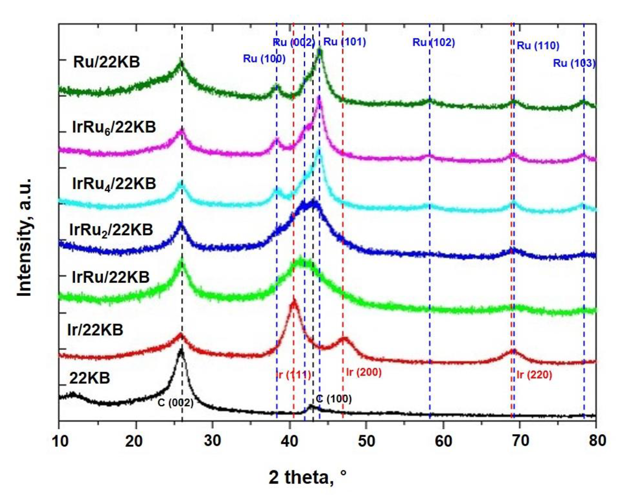
2.2. Catalyst Characterization

Figure 1 shows the XRD patterns of the synthesized Ir/Ru catalysts supported on 22 KB (IrxRuy/22 KB). The obtained peaks were compared with the Joint Committee on powder diffraction standards database patterns for Ir (red line in Figure 1, card no. 06-0598) and Ru (blue line in Figure 1, 06-0663), which are indicated on the peaks of Ir/22 KB and Ru/22 KB, as shown in Figure 1. While the Ir/22 KB catalyst particles had a face-centered cubic (FCC) crystal structure, the synthesized Ru/22 KB catalyst particles formed a hexagonal closely packed (HCP) crystal structure. Deconvolution of the diffraction patterns of the Ir and Ru binary alloys has not been carried out, yet some trends were obvious. Specifically, as the Ru content increased from IrRu/22 KB to IrRu6/22 KB, the primary peak position shifted from 2θ = 40.657° to 44.008°. In the case of IrRu/22 KB and IrRu2/22 KB, the main peak is very broad and difficult to assign the corresponding planes compared to the monometallic Ir/22 KB and Ru/22 KB, which suggest the two catalysts comprise of the random alloy structure of IrRu. The XRD patterns of IrRu4/22 KB and IrRu6/22 KB resembled that of Ru/22 KB. Further, for IrRu4/22 KB and IrRu6/22 KB, a small peak corresponding to Ru (100) appeared before the main Ru (101) peak of the HCP. It can be seen that due to the higher Ru content, the synthesized IrRu4 and IrRu6 catalysts exhibited the HCP crystal structure of Ru. This indicates that the obvious HCP structure of IrRu alloy has appeared from these compositions. Therefore, XRD analysis implied that Ir and Ru formed binary alloys.
All prepared catalysts were subjected to the TGA analysis in the air atmosphere. The TGA results were collected in order to estimate the total precious group metal (PGM) weight loading of each synthesized catalyst, which are summarized in Table 1. In addition, for IrRu4/KB, ICP–ES analysis was conducted to verify whether it is similar to the PGM weight loading estimated from the TGA. The Ir/Ru atomic ratio obtained from the ICP–ES analysis, i.e., 1:3.94, matched well with the target Ir/Ru ratio of 1:4. Furthermore, the measured total PGM loading from ICP–ES analysis was close to that estimated from the TGA. Based on these results, it was assumed that the other Ir and Ru binary alloys were prepared with the intended compositions.
Additionally, the PGM weight loading of the catalysts estimated from TGA, such as 28.2 wt.% for IrRu4/22 KB, for example, were later used for calculating the PGM loading level (LL) in the anode catalyst layer, e.g., 0.053 mgIrRu4/cm2.

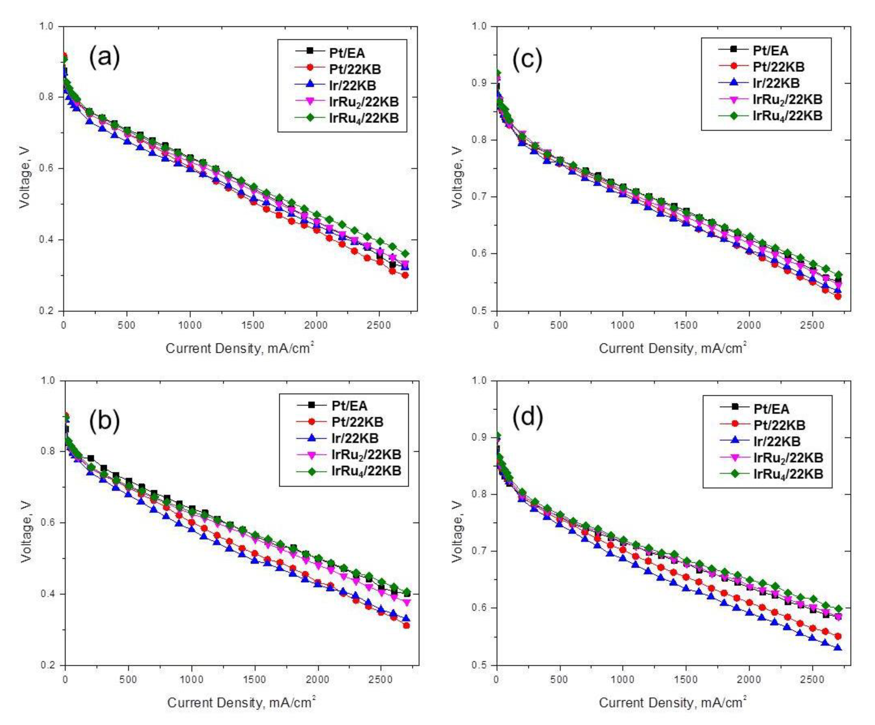
2.3. MEA Performance

MEAs prepared using representative anode catalysts, namely, Pt/EA, Pt/22 KB, IrRu4/22 KB, IrRu2/22 KB, and Ir/22 KB, were used for single-cell performance tests at four different conditions, as described in Section 3.3. The IV polarization curves of these MEAs (Figure 2) show that the MEAs performed better under conditions of 90 °C/150 kPag than at 65 °C/ambient pressure. However, the performance differences between the various anode MEAs decreased at higher temperatures, lower RH, and back pressurized conditions. From the polarization curves, we concluded that non-Pt-based catalysts, specifically, Ir, IrRu2, and IrRu4, show comparable performances to MEAs with Pt-based anodes; this is in agreement with the half-cell results for HOR activity reported by Jin et al. [40]. In addition, Durst et al. proposed Ir/C anode catalysts as a replacement for Pt/C, which showed minor performance loss (<20 mV at 1.5 A/cm2 at 0.1 mgPGM/cm2), but with 3-fold lower startup/shutdown degradation rates [46]. Therefore, in terms of the MEA performance, the catalyst materials based on
IrRu alloys presented here are undoubtedly suitable for replacing Pt in the anodes of MEAs for PEMFCs [34].

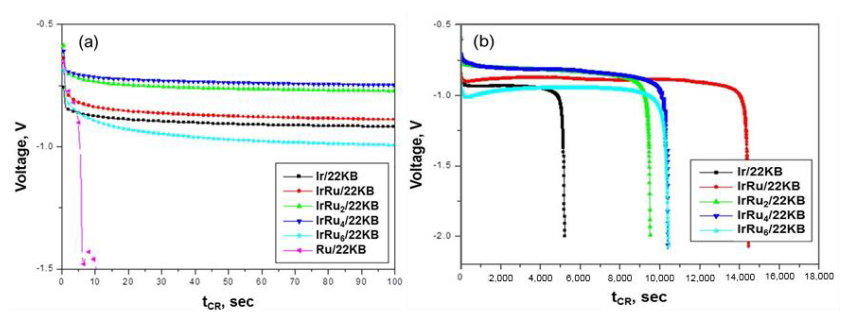
2.4. Cell Reversal Tolerance of Various Anode MEAs

In this work, we subjected various anode catalyst MEAs to simulated CR conditions as described in Section 3.4. During these experiments, chronopotentiometry curves (hereafter denoted as V–t curves) were obtained and used to analyze the CR tolerance of different anode MEAs. Typically, the V–t curves showed the following behavior. The cell voltage dropped to negative potentials as soon as the CR experiment was initiated by drawing a current of 0.2 A/cm2 under fuel-deficient conditions. After this initial abrupt drop, the cell voltage exhibited a steady decrease with time. Finally, the voltage was drastically descended to −2.0 V and the CR experiment was terminated.
Figure 3 shows V–t curves of the single-cell MEAs using Ir/22 KB, Ru/22 KB and various bimetallic alloy catalysts with different Ir/Ru ratios. Figure 3a shows V–t curves of each catalyst within the initial 100 s of the CR period and Figure 3b shows the same curves for the complete experiment. Table 2 summarizes the total PGM, Ir and Ru loading levels (LL, mg/cm2) in the anode and CR test results for each MEA. It should be noted that values are given in the table for representative purposes and do not show the variability of the results.
As can be seen from Figure 3a, two steps were observed in the V–t curve of Ru/22 KB: the first step showed a steep voltage drop from −0.74 to −0.9 V and the second step exhibited a voltage drop from −1.4 to −1.8 V. During the first step, it is expected that water oxidation catalyzed by Ru took place initially, and oxidation and dissolution of Ru occurred simultaneously. It is well known that Ru suffers from severe corrosion at high potentials [41,42]. Therefore, Ru dissolution in the anode should occur immediately under CR conditions, thereby preventing water oxidation and the production of electrons [42,47]. The control CR experiment using pure 22 KB carbon support without any metallic catalyst in the anode was also performed, and its V–t curve is compared with those of Pt/22 KB, Ir/22 KB and Ru/22 KB, shown in Figure S2. The V–t curves of Ru/22 KB and 22 KB resemble each other, and it indicates that the COR probably occurred during the second step for Ru/22 KB. Due to the intrinsic instability of Ru, the tCR,−2.0 V of Ru/22 KB was ~12 s. In contrast to Ru/22 KB, only one step was observed in the V–t curve of Ir/22 KB; at the start of the experiment, the catalyst exhibited a gradual voltage decrease from −0.84 to −0.91 V. In addition, the tCR,−2.0 V of Ir was more than 5000 s, thereby it is inferred that Ir has significantly higher CR tolerance than Ru.
Comparing the initial voltages of binary alloy catalysts during CR tests (Figure 3a), the absolute cell potentials increased in the following order: IrRu4 <IrRu2 <IrRu <IrRu6, with IrRu6 showing the largest negative potential. Notably, a lower absolute cell potential implies that the water oxidation takes place at a lower voltage; hence, the catalyst is more active towards the OER. Furthermore, considering Ir, IrRu, IrRu2 and IrRu4, as the Ru content increased, the absolute initial voltage after 1 s decreased (Table 2), which implied that the OER activity also increased. The OER activities of these catalysts were even higher than those of Ru and Ir, which revealed the synergistic effects of OER–active Ir and Ru. However, in the case of IrRu6/22 KB, the voltage was initially slightly higher than that of Ir (IrRu6: −0.797 V; Ir: −0.839 V), but then rapidly dropped to even lower values (IrRu6: −0.977 V; Ir: −0.91 V) after 60 s. Therefore, it seems that the characteristic behavior of IrRu6 was predominantly influenced by the unstable Ru.
Applying the Ir/Ru binary alloys for the anode catalysts remarkably improved the CR durability under fuel starvation. Since the PGM LLs (i.e., Ir and Ru contents) have differed, a direct comparison of the different binary compositions on the CR tolerance was not straightforward. However, even a small amount of Ir significantly increased the CR tolerance by strengthening the catalyst’s OER stability, as concluded from comparing the initial voltages and tCR,−2.0 V values of Ru/22 KB and IrRu6/22 KB. In addition, comparing these same values for Ir/22 KB and IrRu/22 KB implied that even small amounts of Ru remarkably improved the CR durability of the MEA by enhancing the catalyst’s OER activity.

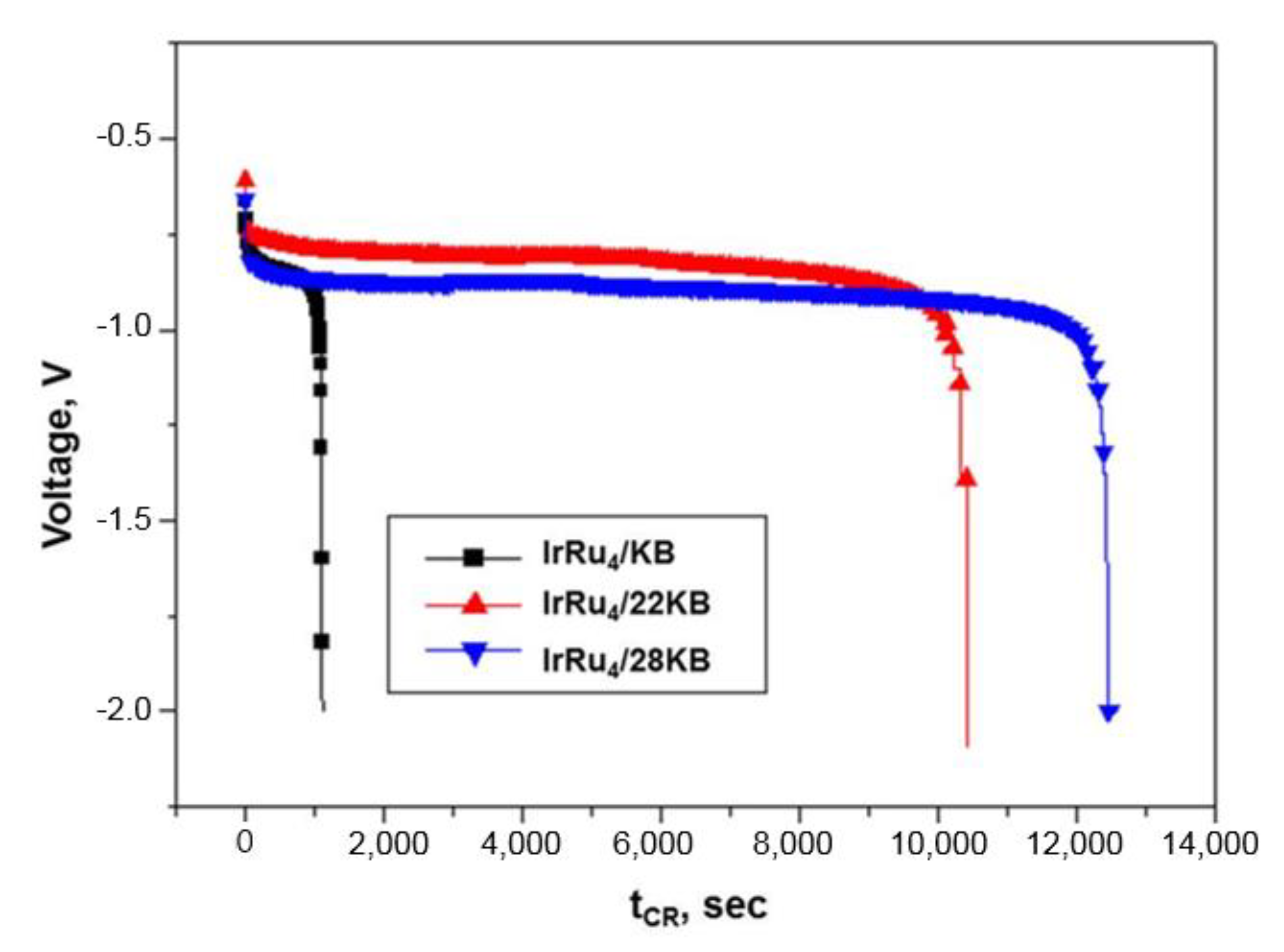
2.5. Effect of Carbon Support on CR Tolerance

Previous studies reported that carbon supports with a high degree of graphitization enhanced the durability of catalyst layers under fuel starvation and other transient conditions [7,15,48,49,50,51]. As the IrRu4 composition showed the best MEA performance among the compositions studied here, and its single-cell performance was comparable to the commercial Pt catalyst, IrRu4 composition was fixed for the following carbon support study. Three carbon supports were used to prepare IrRu4/KB, IrRu4/22 KB and IrRu4/28 KB samples for further testing. These catalysts were used to fabricate the corresponding anode MEAs to evaluate the effect of the degree of graphitization of the carbon support on the CR tolerance. Figure 4 shows V–t curves during CR of single-cell MEAs with IrRu4 catalyst dispersed on different carbon supports having different graphitization degrees. The CR test results are summarized in Table 3. The PGM LLs (mgPGM/cm2) were slightly different, yet the metal catalyst materials were all IrRu4 with ~30 wt% metal loading. Although the catalysts were all nominally IrRu4, the initial voltages at 1 s and 60 s after the CR test was started were different and did not show a consistent trend. However, the tCR,−2.0 V of IrRu4 catalysts increased significantly with heat-treatment temperature: 0.31 h for IrRu4/KB, 2.89 h for IrRu4/22 KB and 3.46 h for IrRu4/28 KB; this implies that a higher degree of carbon graphitization provided higher CR durability. In fact, by changing only the degree of graphitization of the carbon support, the durability of the RTA was increased by a factor of 10, as listed in Table 3. During CR tests, both water oxidation (evolving oxygen) and COR seem to take place at the anode. Therefore, it is expected that the absolute amounts of both the OER catalyst and carbon materials will greatly influence the tCR,−2.0 V. In this respect, higher PGM LLs would result in higher tCR,−2.0 V values. In addition, it was evident that the higher degree of graphitization of the carbon support increased the time for a cell to show abrupt voltage changes. Thus, to enhance the CR tolerance using a new catalyst, one should consider combining stable support under high potential and a multifunctional catalytic composition, such as IrRu alloys, to achieve both high HOR and OER activity. Future studies will investigate the influence of combining metal oxide support with IrRu-based catalysts to develop improved RTAs.

3. Materials and Methods

3.1. Preparation of the IrxRuy/C Catalysts

Ir, Ru and various Ir–Ru binary catalysts (Ir:Ru ratios of 1:0, 1:1, 1:2, 1:4, 1:6 and 0:1) were dispersed on carbon support using a facile impregnation method followed by reduction under an H2/N2 atmosphere in a tube furnace at 573 K (300 °C) to achieve ~30 wt% PGM loading. Dihydrogen hexachloroiridate (IV) hydrate (Heraeus, Germany) and ruthenium (III) chloride hydrate (Heraeus, Hanau, Germany) were used as metal precursors for Ir and Ru, respectively.
As reported by others [35,39], the impregnation was performed by first dispersing carbon support powder in ethyl alcohol under ultrasonication, followed by vortex mixing the Ir and Ru precursors predissolved in ethyl alcohol. After vigorous mixing, the solvent was evaporated using a rotary evaporator and the remaining solid was dried at 353 K overnight. The obtained samples were pulverized using a mortar and pestle and finally reduced at 573 K in a tube furnace under a mixed H2/N2 gas flow.
Four types of Ketjenblack (KB) carbon supports were used: commercially available KB 300 J; KB 300 J thermally treated at 1273 K (1000 °C) and 2473 K (2200 °C) in a furnace in-house under inert atmosphere; and KB carbon heat-treated above 3073 K (2800 °C) purchased from a supplier (hereafter denoted as KB, 10 KB, 22 KB and 28 KB, respectively). The prepared catalysts were named according to the type of carbon support used and the Ir/Ru atomic ratio. For example, IrRu4/22 KB refers to an Ir:Ru atomic ratio of 1:4 supported on the 22 KB carbon. Pt and Pt-based catalysts were purchased from RTX (Deajeon, Korea) and Tanaka Kikinzoku Kogyo (Tokyo, Japan) and were used as received.

3.2. Physicochemical Characterization of Synthesized Catalysts

Powder XRD patterns were collected using a Philips X’Pert Pro X-ray diffractometer with a Cu-Kα radiation source. ICP–ES was used to investigate the content of Ir, Ru and carbon for a selected sample. TGA (TA Instruments, New Castle, DE, USA) was used to estimate the total metal loading of all synthesized catalysts. For the TGA, the change of the catalyst weight was recorded while the catalyst was heat-treated from the room temperature to 1173 K (ramp rate: 5 K/min) while air gas was flowing. After this process, the carbon support is all burnt and removed, and the final sample weight reflects the weight of the oxide of the synthesized catalyst, which later was adapted for the PGM LL calculation. Nitrogen adsorption/desorption isotherms were obtained (ASAP 2020, Micromeritics, Norcross, GA, USA) and used to determine the Brunauer–Emmett–Teller (BET) surface area of the carbon supports heat-treated at different temperatures. Raman spectroscopy was used to quantify the degree of graphitization of the carbon supports for samples prepared at different heat-treatment temperatures.

3.3. Preparation and IV-Performance Evaluation of MEAs

To fabricate the MEAs, a commercial 52 wt.% PtCo/C (TEC36 F52) catalyst was chosen for the cathode, while the various aforementioned as-synthesized and purchased catalysts were used in the anode. The catalyst slurries were prepared by ball milling mixtures of catalyst powders, appropriate amounts of a perfluorosulfonic-acid-type ionomer dispersion, an organic solvent and deionized water. The solid content of the catalyst slurry was 10 wt.%–13 wt.%, which was viscous enough to prevent particle sedimentation. The prepared catalyst slurries were coated onto decal films and dried overnight in an oven at 333 K. Catalyst-coated membranes with an active area of 26 cm2 were fabricated by placing a perfluorosulfonic-acid polytetrafluoroethylene (PTFE)-based membrane between the anode and cathode catalyst layers via the decal transfer technique. The Pt loading in the cathode was 0.18 mgPt/cm2, while the PGM loading in the anodes was 0.02–0.06 mgPGM/cm2, where these PGM LLs were back-calculated from the weight change of the catalyst layer-coated decal film before and after the decal transfer. The MEAs were fabricated by attaching gas diffusion layers to both sides of the electrodes.
Single cells were assembled for the MEAs of representative anode catalysts with a pair of graphite blocks with single serpentine flow fields for the reactants. I–V polarization curves were obtained to characterize the single-cell performances using a test station (SciTech Korea Co., Inc., Seoul, Korea). The MEA performances were evaluated at: (1) 338 K (65 °C), 50% relative humidity (RH), ambient pressure; (2) 338 K (65 °C), 100% RH, ambient pressure; (3) 363 K (90 °C), 50% RH, 150 kPag; and (4) 363 K (90 °C), 100% RH, 150 kPag. Hydrogen and air fuel gases were supplied to the anode and cathode at stoichiometric ratios (SRs) of 1.5 and 2.0, respectively, for ambient pressure testing and 1.2 and 2.0, respectively, for back-pressurized conditions.

3.4. Anode Cell Reversal Durability Test Method

The anode durability of the various anode-MEAs was tested by interrupting the fuel supply at the anode to cause CR. In order to mimic fuel starvation conditions, N2 was supplied to the anode instead of H2, and the air was supplied to the cathode. A single-cell MEA was operated at 65 °C, 50% RH and ambient pressure with SRs of 1.5 and 2.0 for the anode and cathode, respectively; the cell was subjected to these conditions for at least 30 min before starting the measurements. The CR test was initiated by setting the current density to 0.2 A/cm2. The elapsed time after the start of CR (tCR) until the voltage reached −2.0 V (tCR,−2.0 V) was measured. For safety purposes, the minimum voltage was set to −2.1 V so that the instrument could shut down the CR test automatically beyond the minimum voltage.

4. Conclusions

Although a cell reversal during the operation of PEMFCs in FCEVs is inevitable, its consequences can be alleviated by designing advanced anode materials. In this study, we discussed the selection of anode catalysts in terms of effective materials and the degree of graphitization of the carbon support. The dispersing metals were varied from a single component to binary components with differing compositions (Ir:Ru = 1:0, 1:1, 1:2, 1:4, 1:6 and 0:1 (mol/mol)). IrxRuy/C catalysts were synthesized by a simple impregnation method using metal salts and carbon support and a successive reduction in a hydrogen atmosphere at 573 K. From the XRD patterns, it was suggested the crystal structure of the IrRu alloy is changed from the FCC of the Ir to HCP of the Ru with increasing the Ru contents. Further, by increasing the thermal treatment temperature, the graphitization of carbon support is increased supported by the Raman spectra, the BET surface area of the carbon support is decreased, inversely.
While MEAs incorporating IrRu alloy catalysts showed Pt-comparable performance at 363 K, the IrRu alloy anode showed incomparably higher CR durability than the conventional Pt-based MEA. For IrxRuy alloy catalysts, the synergetic effects of Ir and Ru on the CR durability were found: Ir strengthens the catalyst’s OER stability and Ru enhances the catalyst’s OER activity, as it was previously investigated by other researchers [41,42]. Moreover, dispersing the active IrRu4 alloy nanoparticles on highly graphitized carbon support enhanced the CR durability by a factor of 10. Furthermore, it should be highlighted that the IrRu alloy catalyst could completely replace Pt in the anode by acting as a sole anode component. In conclusion, we demonstrated that the binary alloy of OER–active Ir and Ru (preferably IrRu, IrRu2 and IrRu4) is a promising anode component that features both good HOR activity and excellent CR tolerance properties. Based on the results of our work, we conclude that the development of an RTA catalyst requires a smart selection of both support that is stable under high voltage and an active metal composition that exhibits high HOR and OER activities simultaneously.

Supplementary Materials

The following are available online at https://www.mdpi.com/2073-4344/10/8/932/s1, Figure S1: Raman spectra of KB, 10 KB, 22 KB and 28 KB carbon supports, normalized to the same maximum peak height, Figure S2: Voltage–time (V–t) plot of 22 KB, Ru/22 KB, Ir/22 KB and Pt/22 KB anode MEAs, Table S1: N2 adsorption BET surface areas and Raman spectroscopic parameters of the carbon black supports.

Author Contributions

Conceptualization, E.Y. and C.P.; methodology, E.Y. and D.Y.; formal analysis, E.Y. and D.Y.; investigation, S.W.L. and B.L.; data curation, E.Y.; writing—original draft preparation, E.Y.; writing—review and editing, E.Y., S.W.L., B.L., D.Y. and C.P.; funding acquisition, C.P. All authors have read and agreed to the published version of the manuscript.

Funding

This research was funded by Hyundai Mobis, Grant Number GI06280.

Acknowledgments

C.P. thanks to the support from the GIST Research Institute (GRI) grant (GK12490) funded by the Gwangju Institute of Science and Technology in 2020.

Conflicts of Interest

The authors declare no conflict of interest.

References

  1. Banham, D.; Ye, S. Current status and future development of catalyst materials and catalyst layers for proton exchange membrane fuel cells: An industrial perspective. ACS Energy Lett. 2017, 2, 629–638. [Google Scholar] [CrossRef]
  2. Kongkanand, A.; Mathias, M.F. The priority and challenge of high-power performance of low-platinum proton-exchange membrane fuel cells. J. Phys. Chem. Lett. 2016, 7, 1127–1137. [Google Scholar] [CrossRef] [PubMed]
  3. Daud, W.; Rosli, R.; Majlan, E.; Hamid, S.; Mohamed, R.; Husaini, T. PEM fuel cell system control: A review. Renew. Energy 2017, 113, 620–638. [Google Scholar] [CrossRef]
  4. Martínez-Huerta, M.; Lázaro, M. Electrocatalysts for low temperature fuel cells. Catal. Today 2017, 285, 3–12. [Google Scholar] [CrossRef] [Green Version]
  5. Chen, H.; Zhao, X.; Zhang, T.; Pei, P. The reactant starvation of the proton exchange membrane fuel cells for vehicular applications: A review. Energy Convers. Manag. 2019, 182, 282–298. [Google Scholar] [CrossRef]
  6. Hong, B.K.; Mandal, P.; Oh, J.-G.; Litster, S. On the impact of water activity on reversal tolerant fuel cell anode performance and durability. J. Power Sources 2016, 328, 280–288. [Google Scholar] [CrossRef]
  7. Qin, C.; Wang, J.; Yang, D.; Li, B.; Zhang, C. Proton exchange membrane fuel cell reversal: A review. Catalysts 2016, 197, 1–21. [Google Scholar] [CrossRef]
  8. Atanasoski, R.T.; Vernstrom, G.D.; Haugen, G.M.; Watschke, T.M.; Wheldon, J.M.; Hendricks, S.M.; Atanasoska, L.L.; Hesteret, A.E. V.D.3 Durable Catalysts for Fuel Cell Protection During Transient Conditions. In Proceedings of the Annual Merit Review DOE Hydrogen and Fuel Cells Program, Arlington, VA, USA, 9–13 May, 2011. [Google Scholar]
  9. Lim, K.H.; Lee, W.H.; Jeong, Y.; Kim, H. Analysis of carbon corrosion in anode under fuel starvation using on-line mass spectrometry in polymer electrolyte membrane fuel cells. J. Electrochem. Soc. 2017, 164, F1580–F1586. [Google Scholar] [CrossRef]
  10. Roh, C.-W.; Kim, H.-E.; Choi, J.; Lim, J.; Lee, H. Monodisperse IrOx deposited on Pt/C for reversal tolerant anode in proton exchange membrane fuel cell. J. Power Sources 2019, 443, 227270. [Google Scholar] [CrossRef]
  11. Hong, B.K.; Kim, S.H.; Kim, C.M. Powering the future through hydrogen and polymer electrolyte membrane fuel cells. Johns. Matthey Technol. Rev. 2020, 64, 236. [Google Scholar] [CrossRef]
  12. Pak, C.; Lee, S.W.; Baik, C.; Lee, B.H.; You, D.J.; You, E. New strategy for reversal tolerant anode for automotive polymer electrolyte fuel cell. Chin. Chem. Lett. 2019, 30, 1186–1189. [Google Scholar] [CrossRef]
  13. Hong, B.K.; Kim, S.H. Recent advances in fuel cell electric vehicle technologies of Hyundai. ECS Trans. 2018, 86, 3–11. [Google Scholar] [CrossRef]
  14. Shen, G.; Liu, J.; Wu, H.B.; Xu, P.; Liu, F.; Tongsh, C.; Jiao, K.; Li, J.; Liu, M.; Cai, M. Multi-functional anodes boost the transient power and durability of proton exchange membrane fuel cells. Nat. Commun. 2020, 11, 1–10. [Google Scholar] [CrossRef] [PubMed] [Green Version]
  15. Wang, Y.-J.; Fang, B.; Li, H.; Bi, X.T.; Wang, H. Progress in modified carbon support materials for Pt and Pt-alloy cathode catalysts in polymer electrolyte membrane fuel cells. Prog. Mater. Sci. 2016, 82, 445–498. [Google Scholar] [CrossRef]
  16. Jung, W.S.; Popov, B.N. Improved durability of Pt catalyst supported on N-doped mesoporous graphitized carbon for oxygen reduction reaction in polymer electrolyte membrane fuel cells. Carbon 2017, 122, 746–755. [Google Scholar] [CrossRef]
  17. Jung, W.S.; Popov, B.N. Hybrid cathode catalyst with synergistic effect between carbon composite catalyst and Pt for ultra-low Pt loading in PEMFCs. Catal. Today 2017, 295, 65–74. [Google Scholar] [CrossRef]
  18. Park, Y.-B.; You, E.; Pak, C.; Min, M. Preparation and characterization of durable catalyst via diazonium reaction in PEMFC. Electrochim. Acta 2018, 284, 242–252. [Google Scholar] [CrossRef]
  19. Lori, O.; Elbaz, L. Advances in ceramic supports for polymer electrolyte fuel cells. Catalysts 2015, 5, 1445–1464. [Google Scholar] [CrossRef] [Green Version]
  20. Wang, Y.-J.; Wilkinson, D.P.; Neburchilov, V.; Song, C.; Guest, A.; Zhang, J. Ta and Nb co-doped TiO2 and its carbon-hybrid materials for supporting Pt–Pd alloy electrocatalysts for PEM fuel cell oxygen reduction reaction. J. Mater. Chem. A 2014, 2, 12681–12685. [Google Scholar] [CrossRef]
  21. Kim, J.-H.; Kwon, G.; Lim, H.; Zhu, C.; You, H.; Kim, Y.-T. Effects of transition metal doping in Pt/M-TiO2 (M = V, Cr, and Nb) on oxygen reduction reaction activity. J. Power Sources 2016, 320, 188–195. [Google Scholar] [CrossRef]
  22. Jeon, Y.; Ji, Y.; Cho, Y.I.; Lee, C.; Park, D.-H.; Shul, Y.-G. Oxide–carbon nanofibrous composite support for a highly active and stable polymer electrolyte membrane fuel-cell catalyst. ACS Nano 2018, 12, 6819–6829. [Google Scholar] [CrossRef]
  23. Mandal, P.; Hong, B.K.; Oh, J.-G.; Litster, S. Understanding the voltage reversal behavior of automotive fuel cells. J. Power Sources 2018, 397, 397–404. [Google Scholar] [CrossRef]
  24. Yi, M.H.; Choi, J.S.; Rho, B. Synthesis and durability of carbon-supported catalysts for PEMFC. Trans. Korean Hydrog. New Energy Soc. 2015, 26, 318–323. [Google Scholar] [CrossRef] [Green Version]
  25. Moore, C.E.; Eastcott, J.; Cimenti, M.; Kremliakova, N.; Gyenge, E.L. Novel methodology for ex situ characterization of iridium oxide catalysts in voltage reversal tolerant proton exchange membrane fuel cell anodes. J. Power Sources 2019, 417, 53–60. [Google Scholar] [CrossRef]
  26. Hu, L.; Hong, B.K.; Oh, J.-G.; Litster, S. Robust operation of fuel cell systems in subfreezing conditions: A material-based solution to achieve better anode durability. Acs Appl. Energy Mater. 2019, 2, 7152–7161. [Google Scholar] [CrossRef]
  27. Cai, C.; Wan, Z.; Rao, Y.; Chen, W.; Zhou, J.; Tan, J.; Pan, M. Water electrolysis plateau in voltage reversal process for proton exchange membrane fuel cells. J. Power Sources 2020, 455, 227952. [Google Scholar] [CrossRef]
  28. Joo, T.; Hu, L.; Hong, B.K.; Oh, J.-G.; Litster, S. On the origin of deactivation of reversal-tolerant fuel cell anodes under voltage reversal conditions. J. Power Sources 2020, 472, 228439. [Google Scholar] [CrossRef]
  29. Ralph, T.R.; Hudson, S.; Wilkinson, D.P. Electrocatalyst stability in PEMFCs and the role of fuel starvation and cell reversal tolerant anodes. ECS Trans. 2006, 1, 67–84. [Google Scholar] [CrossRef]
  30. Cullen, D.A.; More, K.L.; Atanasoska, L.L.; Atanasoski, R.T. Impact of IrRu oxygen evolution reaction catalysts on Pt nanostructured thin films under start-up/shutdown cycling. J. Power Sources 2014, 269, 671–681. [Google Scholar] [CrossRef] [Green Version]
  31. Zhou, X.; Ji, H.; Li, B.; Zhang, C. High-repetitive reversal tolerant performance of proton-exchange membrane fuel cell by designing a suitable anode. ACS Omega 2020, 5, 10099–10105. [Google Scholar] [CrossRef]
  32. Wang, J.; Zhou, X.; Li, B.; Yang, D.; Lv, H.; Xiao, Q.; Ming, P.; Wei, X.; Zhang, C. Highly efficient, cell reversal resistant PEMFC based on PtNi/C octahedral and OER composite catalyst. Int. J. Hydrog. Energy 2020, 45, 8930–8940. [Google Scholar] [CrossRef]
  33. Pătru, A.; Rabis, A.; Temmel, S.E.; Kotz, R.; Schmidt, T.J. Pt/IrO2–TiO2 cathode catalyst for low temperature polymer electrolyte fuel cell–Application in MEAs, performance and stability issues. Catal. Today 2016, 262, 161–169. [Google Scholar] [CrossRef]
  34. Zhu, Z.; Yan, X.; Tang, H.; Cai, H.; Pan, M.; Zhang, H.; Luo, J. Protic ionic liquid modified electrocatalyst enables robust anode under cell reversal condition. J. Power Sources 2017, 351, 138–144. [Google Scholar] [CrossRef]
  35. You, E.; Min, M.; Jin, S.-A.; Kim, T.; Pak, C. Highly durable, cost-effective, and multifunctional carbon-supported IrRu-based catalyst for automotive polymer electrolyte fuel cell anodes. J. Electrochem. Soc. 2018, 165, F3094–F3099. [Google Scholar] [CrossRef] [Green Version]
  36. Lee, S.W.; Lee, B.; Baik, C.; Kim, T.-Y.; Pak, C. Multifunctional Ir–Ru alloy catalysts for reversal-tolerant anodes of polymer electrolyte membrane fuel cells. J. Mater. Sci. Technol. 2021, 60, 105–112. [Google Scholar] [CrossRef]
  37. Kim, T.-Y.; Lee, S.W.; Pak, C. Optimization of carbon-supported Ir–Ru alloys for polymer electrolyte fuel cell anodes under cell reversal. J. Ind. Eng. Chem. 2020, 85, 87–93. [Google Scholar] [CrossRef]
  38. Lee, S.W.; Lee, B.H.; Kim, T.-Y.; Baik, C.; Kim, M.S.; Chai, G.S.; Pak, C. Multifunctional non-Pt ternary catalyst for the hydrogen oxidation and oxygen evolution reactions in reversal-tolerant anode. Catal. Commun. 2019, 130, 105758. [Google Scholar] [CrossRef]
  39. You, E.; You, D.; Lee, S.; Pak, C. Design of anode catalyst material for a cell reversal tolerant MEA: Ir, Ru, and their binary alloys supported on carbon black. 2018 ECS Meet. Abstr. 2018, 2, 1470. [Google Scholar]
  40. Jin, S.-A.; Pak, C.; Yoo, D.J.; Lee, K.H. Electrode catalyst for fuel cell, method of preparing the same, and membrane electrode assembly and fuel cell including electrode catalyst. US Pat. Appl. 2013, 13, 426. [Google Scholar]
  41. Cherevko, S.; Geiger, S.; Kasian, O.; Kulyk, N.; Grote, J.-P.; Savan, A.; Shrestha, B.R.; Merzlikin, S.; Breitbach, B.; Ludwig, A. Oxygen and hydrogen evolution reactions on Ru, RuO2, Ir, and IrO2 thin film electrodes in acidic and alkaline electrolytes: A comparative study on activity and stability. Catal. Today 2016, 262, 170–180. [Google Scholar] [CrossRef]
  42. Reier, T.; Oezaslan, M.; Strasser, P. Electrocatalytic oxygen evolution reaction (OER) on Ru, Ir, and Pt catalysts: A comparative study of nanoparticles and bulk materials. ACS Catal. 2012, 2, 1765–1772. [Google Scholar] [CrossRef]
  43. Pantea, D.; Darmstadt, H.; Kaliaguine, S.; Sümmchen, L.; Roy, C. Electrical conductivity of thermal carbon blacks: Influence of surface chemistry. Carbon 2001, 39, 1147–1158. [Google Scholar] [CrossRef]
  44. Loupe, N.; Doan, J.; Smotkin, E.S. Twenty years of operando IR, X-ray absorption, and Raman spectroscopy: Direct methanol and hydrogen fuel cells. Catal. Today 2017, 283, 11–26. [Google Scholar] [CrossRef]
  45. Jawhari, T.; Roid, A.; Casado, J. Raman spectroscopic characterization of some commercially available carbon black materials. Carbon 1995, 33, 1561–1565. [Google Scholar] [CrossRef]
  46. Durst, J.; Orfanidi, A.; Rheinländer, P.J.; Hasché, F.; Eickes, C.; Suchsland, P.; Binder, M.; Gasteiger, H.A. Selective hydrogen oxidation catalyst for reduced startup/shutdown degradation in low temperature fuel cells. ECS Trans. 2015, 69, 67–76. [Google Scholar] [CrossRef]
  47. Taniguchi, A.; Akita, T.; Yasuda, K.; Miyazaki, Y. Analysis of electrocatalyst degradation in PEMFC caused by cell reversal during fuel starvation. J. Power Sources 2004, 130, 42–49. [Google Scholar] [CrossRef]
  48. Jung, J.; Park, B.; Kim, J. Durability test with fuel starvation using a Pt/CNF catalyst in PEMFC. Nanoscale Res. Lett. 2012, 7, 34–41. [Google Scholar] [CrossRef] [Green Version]
  49. Castanheira, L.; Silva, W.O.; Lima, F.H.; Crisci, A.; Dubau, L.; Maillard, F.D.R. Carbon corrosion in proton-exchange membrane fuel cells: Effect of the carbon structure, the degradation protocol, and the gas atmosphere. ACS Catal. 2015, 5, 2184–2194. [Google Scholar] [CrossRef]
  50. Oh, H.-S.; Lim, K.H.; Roh, B.; Hwang, I.; Kim, H. Corrosion resistance and sintering effect of carbon supports in polymer electrolyte membrane fuel cells. Electrochim. Acta 2009, 54, 6515–6521. [Google Scholar] [CrossRef]
  51. Artyushkova, K.; Atanassov, P.; Dutta, M.; Wessel, S.; Colbow, V. Structural correlations: Design levers for performance and durability of catalyst layers. J. Power Sources 2015, 284, 631–641. [Google Scholar] [CrossRef] [Green Version]
Figure 1. XRD patterns of Ir, IrRu, IrRu2, IrRu4, IrRu6, and Ru supported on 22 KB. The XRD pattern of carbon support 22 KB is also shown for comparison.
Catalysts 10 00932 g001
Figure 2. Polarization curves of polymer electrolyte membrane fuel cells (PEMFCs) with membrane electrode assemblies (MEAs) prepared from various anode catalysts (Pt/EA, Pt/22 KB, Ir/22 KB, IrRu2/22 KB and IrRu4/22 KB) at (a) 65 °C, 50% RH, ambient pressure; (b) 65 °C, 100% RH, ambient pressure; (c) 90 °C, 50% RH, 150 kPa; (d) 90 °C, 100% RH, 150 kPa.
Catalysts 10 00932 g002
Figure 3. Voltage–time (V–t) plot of Ir/22 KB, IrRu/22 KB, IrRu2/22 KB, IrRu4/22 KB, IrRu6/22 KB and Ru/22 KB anode MEAs (a) within initial 100 s during the cell reversal test and (b) during the whole experimental period.
Catalysts 10 00932 g003
Figure 4. Voltage–time (V–t) plot of IrRu4/KB, IrRu4/22 KB and IrRu4/28 KB anode MEAs during the cell reversal test.
Catalysts 10 00932 g004
Table 1. Notation and brief specification of catalysts used in this study. Nonplatinum catalysts were synthesized and Pt-based catalysts * were purchased from commercial suppliers.
CatalystCarbon SupportMetal Loading (wt%)Nominal Atomic Ratio
Ir/22 KB22 KB28.2 (TGA)Ir:Ru = 1:0
IrRu/22 KB28.9 (TGA)Ir:Ru = 1:1
IrRu2/22 KB33.5 (TGA)Ir:Ru = 1:2
IrRu4/22 KB28.2 (TGA)Ir:Ru = 1:4
IrRu6/22 KB29.3 (TGA)Ir:Ru = 1:6
Ru/22 KB29.6 (TGA)Ir:Ru = 0:1
IrRu4/KBKB26.6 (TGA), 24.9 (Ir: 8.1, Ru: 16.8, ICP)Ir:Ru = 1:4
IrRu4/28 KB28 KB25.0 (TGA)Ir:Ru = 1:4
Pt/22 KB *22 KB, RTX30
Pt/EA *EA, graphitized carbon, TKK19.8
PtCo/F *F, stabilized carbon, TKKPt: 48.6, Co: 4.8Pt:Co = 3:1
Table 2. Results of cell reversal test using anodes prepared with Ir, Ru and their alloy catalysts.
Anode CatalystPGM LL (mg/cm2)Ir (mg/cm2)Ru (mg/cm2)Voltage at tCR = 1 s (V)Voltage at tCR = 60 s (V)tCR,−2.0 V (s)
Ir/22 KB0.0330.033-−0.839−0.915231
IrRu/22 KB0.0550.0360.019−0.768−0.87914,454
IrRu2/22 KB0.0540.0260.028−0.69−0.7649516
IrRu4/22 KB0.0530.0170.036−0.687−0.7410,397
IrRu6/22 KB0.0580.0140.044−0.797−0.97710,424
Ru/22 KB0.035-0.035−0.742-12
Table 3. Results of cell reversal tests using IrRu4 dispersed on different types of carbon supports.
Anode CatalystPGM LL
(mg/cm2)
Voltage at tCR = 1 s
(V)
Voltage at tCR = 60 s
(V)
tCR,−2.0 V
(h)
IrRu4/KB0.060−0.688−0.7880.31
IrRu4/22 KB0.053−0.687−0.7402.89
IrRu4/28 KB0.048−0.742−0.8183.46

