
Geometric Error Analysis and Compensation in Spherical Generating Grinding of Hemispherical Shell Resonators
Abstract
:1. Introduction
2. Method
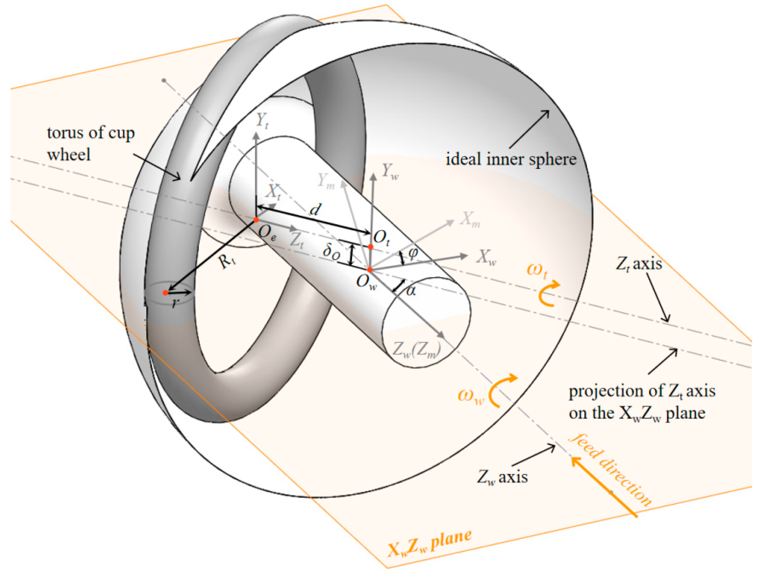
2.1. Analysis of Tool Setting Error on HSR Machining
2.2. Analysis of Tool Wear on HSR Machining
2.3. Compensation Strategy and Process
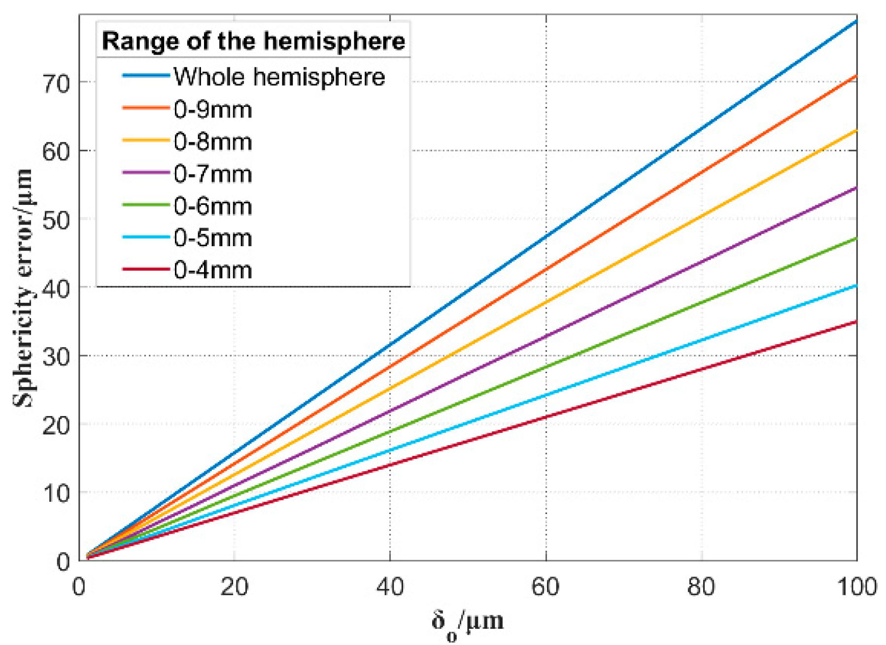
- Adjust δo to make the surface shape an approximate sphere.
- Adjust the feed Fz of the wheel in the Zm direction to ensure the concentricity of the inner and outer spherical surfaces.
- Adjust the wheel position parameter d to make the machining spherical radius meet the requirements.
3. Results and Discussion
3.1. Compensation of Height Error δo
3.2. Compensation of Inner and Outer Spherical Radius and Concentricity Error
4. Conclusions
Author Contributions
Funding
Data Availability Statement
Conflicts of Interest
Nomenclature
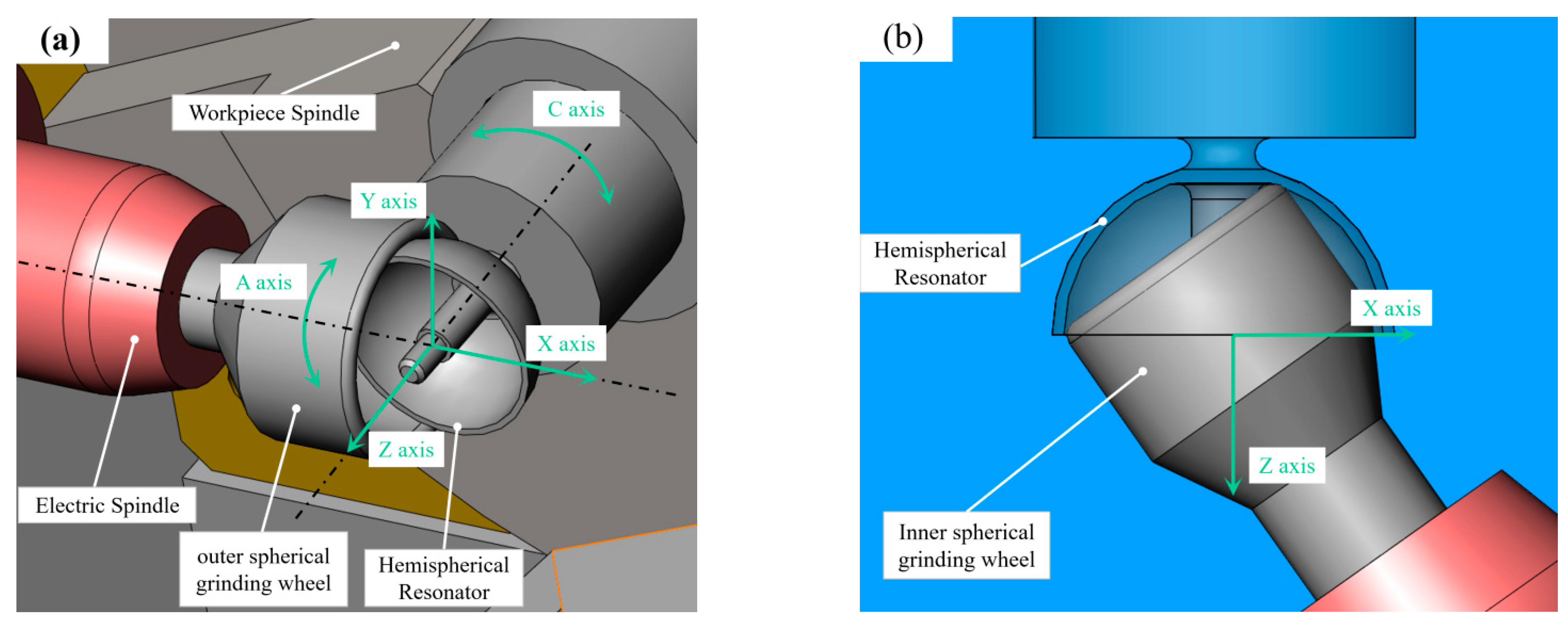
| X, Y, Z, C | Four axes of the machine |
| Xw, Yw, Zw | Three axes of the workpieces |
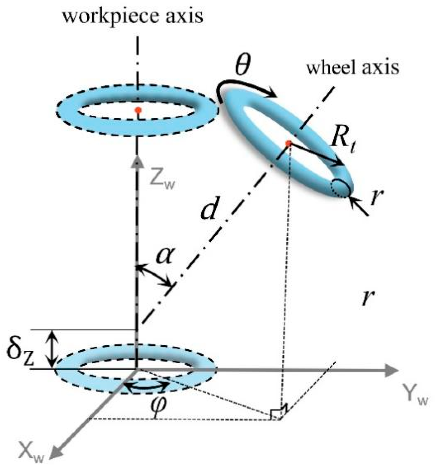
| α | The rotation angle around the Y-axis of wheel |
| φ | The rotation angle around the Z-axis of wheel |
| θ | The spin angle around the Zw-axis of wheel |
| d | the distance from the workpiece axis to the wheel axis |
| x2, y2, z2 | Coordinates of any point on the initial torus |
| x1, y1, z1 | Coordinates of any point on the final torus |
| x0, y0, z0 | Normal equation of any point on the torus |
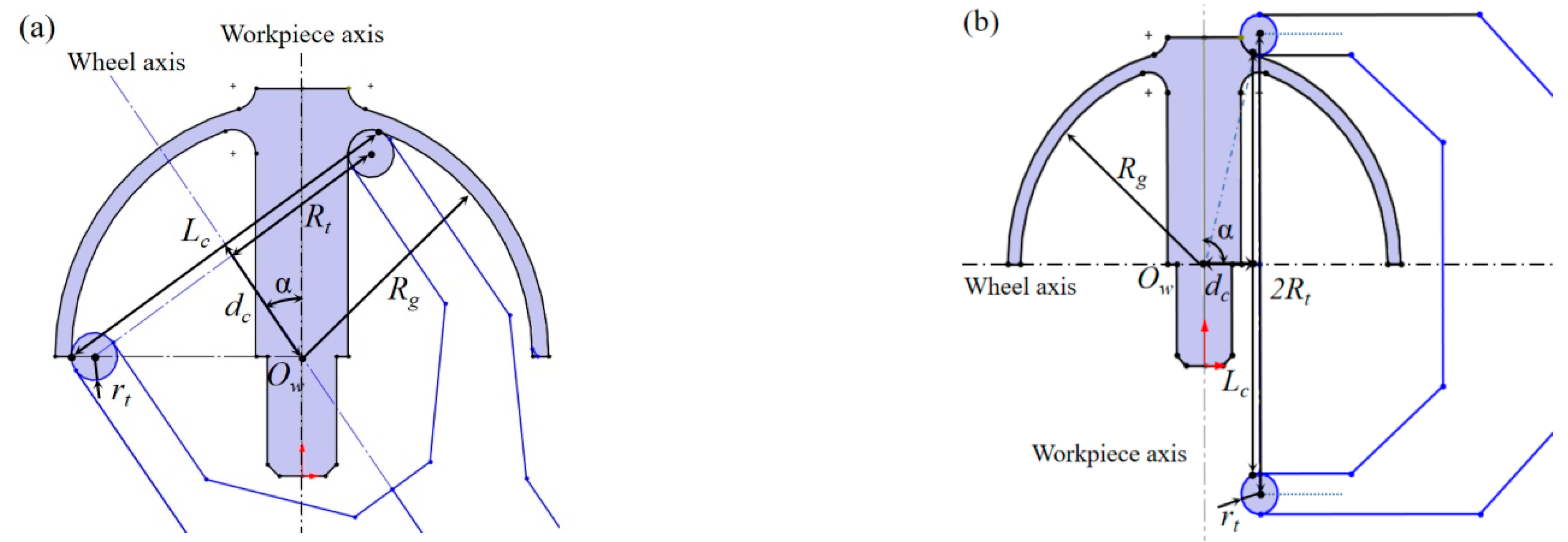
| Rt | Mean radius of the torus |
| r | Arc radius of the torus end |
| Rg | Radius of the spherical surface |
| Ow | Center point of the sphere |
| dc | Distance of the chord center from the Ow |
| Lc | Chord of the workpiece circle on the XwZw plane |
| Ot | Pedal on the Zt axis |
| δr, δRt | Error corresponding to r, Rt |
| δα, δd, δz | Error corresponding to α, d, z |
| δO | Error of the non-intersection between the Zt and Zw |
| Δβ | Angle between Zt axis and XwZw plane |
| Lz | Distance between the point on the sphere and Zw axis |
| x3, y3, z3 | Contour points of the sphere |
| AB | Contact line between wheel and workpiece |
References
- Delhaye, F. HRG by SAFRAN: The game-changing technology. In Proceedings of the 2018 IEEE International Symposium on Inertial Sensors and Systems (INERTIAL), Lake Como, Italy, 26–29 March 2018; pp. 1–4. [Google Scholar]
- Rozelle, D.M. The hemispherical resonator gyro: From wineglass to the planets. In Proceedings of the 19th AAS/AIAA Space Flight Mechanics Meeting, Savannah, Georgia, 8–12 February 2009; pp. 1157–1178. [Google Scholar]
- Joubert, S.V.; Shatalov, M.Y.; Coetzee, C.E. Analysing manufacturing imperfections in a spherical vibratory gyroscope. In Proceedings of the 2011 4th IEEE International Workshop on Advances in Sensors and Interfaces (IWASI), Savelletri di Fasano, Italy, 28–29 June 2011; pp. 165–170. [Google Scholar]
- Chen, Y.; Xi, X.; Shi, Y.; Lu, K.; Xiao, D.; Wu, X. Simulated analysis of forming imperfection for micro shell resonators. Microsyst. Technol. 2021, 27, 723–737. [Google Scholar] [CrossRef]
- Fess, E.; Bechtold, M.; Wolfs, F.; Bechtold, R. Developments in precision optical grinding technology. In Proceedings of the Optifab 2013, Rochester, NY, USA, 14–17 October 2013; SPIE: Bellingham, WA, USA, 2013; pp. 96–100. [Google Scholar]
- Xu, L.; Hu, D.; Dong, W.; Xie, C.; Liu, M. An equivalent-sphere-based grinding of large aspheric and spherical surfaces. Int. J. Adv. Manuf. Technol. 2022, 120, 1663–1676. [Google Scholar] [CrossRef]
- Chen, W.; Huang, H. Ultra-precision grinding of spherical convex surfaces on combination brittle materials using resin and metal bond cup wheels. J. Mater. Process. Technol. 2003, 140, 217–223. [Google Scholar] [CrossRef]
- Gracewski, S.M.; Li, Y.; Zhou, Y.; Funkenbusch, P.D.; Ruckman, J.L. Relationship between microgrinding parameters and lens surface features. In Optical Manufacturing and Testing II; SPIE: Bellingham, WA, USA, 1997; pp. 223–230. [Google Scholar]
- Zhou, B.; Xia, Y. Study on Processing of High Precision Graphite Ball with Four Axis Ball Grinder. In Proceedings of the 4th Annual International Conference on Material Engineering and Application (ICMEA 2017), Wuhan, China, 15–17 December 2017; pp. 239–242. [Google Scholar]
- Kuriyagawa, T.; Zahmaty, M.S.S.; Syoji, K. A new grinding method for aspheric ceramic mirrors. J. Mater. Process. Technol. 1996, 62, 387–392. [Google Scholar] [CrossRef]
- Chen, M.; Li, Z.; Yu, B.; Peng, H.; Fang, Z. On-machine precision preparation and dressing of ball-headed diamond wheel for the grinding of fused silica. Chin. J. Mech. Eng. 2013, 26, 982–987. [Google Scholar] [CrossRef]
- Wei, X.; Li, B.; Chen, L.; Xin, M.; Liu, B.; Jiang, Z. Tool setting error compensation in large aspherical mirror grinding. Int. J. Adv. Manuf. Technol. 2018, 94, 4093–4103. [Google Scholar] [CrossRef]
- Xie, J.; Zhou, R.; Xu, J.; Zhong, Y. Form-truing error compensation of diamond grinding wheel in CNC envelope grinding of free-form surface. Int. J. Adv. Manuf. Technol. 2010, 48, 905–912. [Google Scholar] [CrossRef]
- Guo, B.; Zhao, Q.; Li, H. Ultraprecision grinding of TiC-based cermet hemisphere couples. Int. J. Adv. Manuf. Technol. 2014, 73, 1281–1289. [Google Scholar] [CrossRef]
- Wang, T.; Liu, H.; Wu, C.; Chen, J.; Chen, M. Interference and grinding characteristics in ultra-precision grinding of thin-walled complex structural component using a ball-end grinding wheel. Chin. J. Aeronaut. 2021, 34, 192–207. [Google Scholar] [CrossRef]
- Zhang, Q.; Zhao, Q.; To, S.; Guo, B. A further study of wheel normal grinding of hemisphere couples on TiC-based cermet. Int. J. Adv. Manuf. Technol. 2016, 87, 2593–2602. [Google Scholar] [CrossRef]
- Schäfer, H.; Diehl, J.; Urban, L. Grinding and Polishing Machine for Grinding and/or Polishing Workpieces to an Optical Quality. U.S. Patent No. 7,455,569, 25 November 2008. [Google Scholar]
- Peng, Y.; Dai, Y.; Song, C.; Chen, S. Error analysis and compensation of line contact spherical grinding with cup-shaped wheel. Int. J. Adv. Manuf. Technol. 2016, 83, 293–299. [Google Scholar] [CrossRef]


| Test No. | Sphericity before Compensation/μm | Corresponding δo /μm | Sphericity after Compensation/μm | Corresponding Residual δo /μm |
|---|---|---|---|---|
| 1 | 4.2 | 7.8 | 0.7 | 1.3 |
| 2 | 6.3 | 11.5 | 0.9 | 1.6 |
| 3 | 10.5 | 19.2 | 0.8 | 1.5 |
| 4 | 14.9 | 27.2 | 1.2 | 2.0 |
| 5 | 20.5 | 37.4 | 1.2 | 2.0 |
| Test No. | Radius of Inner Sphere/mm | Radius of Outer Sphere/mm | Concentricity/μm | |||
|---|---|---|---|---|---|---|
| Before | After | Before | After | Before | After | |
| 1 | 9.9903 | 9.9997 | 10.7338 | 10.7010 | 14.7 | 0.6 |
| 2 | 9.9883 | 9.9992 | 10.7582 | 10.7019 | 62.5 | 1.6 |
| 3 | 9.9765 | 9.9990 | 10.7321 | 10.7009 | 52.6 | 1.7 |
| 4 | 9.9558 | 9.9978 | 10.7142 | 10.7006 | 38.5 | 0.8 |
| 5 | 9.9386 | 9.9958 | 10.7685 | 10.7022 | 76.2 | 2.4 |
Publisher’s Note: MDPI stays neutral with regard to jurisdictional claims in published maps and institutional affiliations. |
© 2022 by the authors. Licensee MDPI, Basel, Switzerland. This article is an open access article distributed under the terms and conditions of the Creative Commons Attribution (CC BY) license (https://creativecommons.org/licenses/by/4.0/).
Share and Cite
Wang, Y.; Guan, C.; Dai, Y.; Xue, S. Geometric Error Analysis and Compensation in Spherical Generating Grinding of Hemispherical Shell Resonators. Micromachines 2022, 13, 1535. https://doi.org/10.3390/mi13091535
Wang Y, Guan C, Dai Y, Xue S. Geometric Error Analysis and Compensation in Spherical Generating Grinding of Hemispherical Shell Resonators. Micromachines. 2022; 13(9):1535. https://doi.org/10.3390/mi13091535
Chicago/Turabian StyleWang, Yu, Chaoliang Guan, Yifan Dai, and Shuai Xue. 2022. "Geometric Error Analysis and Compensation in Spherical Generating Grinding of Hemispherical Shell Resonators" Micromachines 13, no. 9: 1535. https://doi.org/10.3390/mi13091535