
The Precision Analysis of Cutting Edge Preparation on CBN Cutting Inserts Using Rotary Ultrasonic Machining


Abstract
:1. Introduction
2. Materials and Methods
3. Results and Discussion
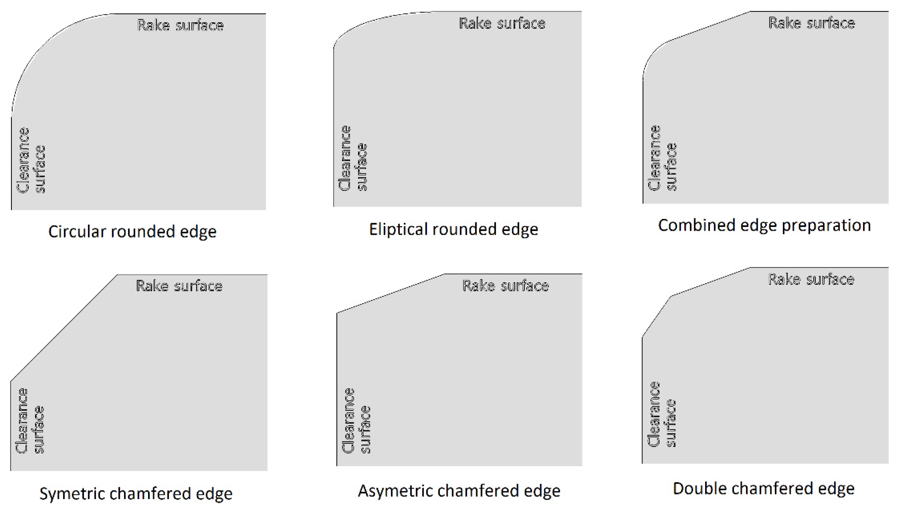
- The cutting edge preparation can have many shapes. Most of the methods are limited to only one shape (usually circular rounding). However, almost any shape can be created using three-axis machining.
- During three-axis machining, the cutting tool´s rake surface produces the cutting edge. The ultrasonic vibrations are perpendicular to the machined surface. There are several tool paths needed, and the resultant machined surface contains very small “cascades.” Although more tool paths cause a smoother surface, the machining time will be longer.
- The process of cutting edge preparation is often time-consuming (even several hours long). However, a chamfer around the whole cutting insert (one side) can be created in a couple of seconds when five-axis machining is used. This is caused by creating a cutting edge using a single tool path. Therefore, the processing time is very little affected by size.
- Five-axis machining can only create chamfers; however, with different sizes and angles.
- During five-axis machining, the lateral surface of the cutting tool produces the cutting edge. The ultrasonic vibrations are parallel to the machined surface and the cutting tool is more affected by the torque.
- CBN is very hard and abrasive. It can wear the lateral surface of the cutting tool during five-axis machining, which decreases the shape and dimensional accuracy.
- The true dimensions of the cutting inserts differing from those written on the inserts box. Therefore, the tool paths that were generated in CAM according to the ideal 3D CAD model are displaced, and the tool´s relative position is changed. This could be solved by the very precise measurement of every single cutting insert before its processing.
- The zero point determined by a tough probe in the machine tool differs from that created in CAM software. The cutting insert is small and there is little space for tough probe movement. Moreover, the tough probe itself may not have been satisfactorily calibrated. Even a small displacement of the zero point from the cutting insert’s center would cause an increase in the cutting edge preparation on one side, and a decrease on the opposite side. This could be solved by applying a specially designed fixture.
- The zero point is determined with translation axes. However, an inclination in the rotational axes could negatively affect the accuracy. Cutting inserts have very small dimensions and it is difficult to measure their inclination. It is recommended to re-measure the inclination for every cutting insert before machining. This could also be solved by applying a specially designed fixture.
- Rapid tool wear causes changes in the cutting tool´s dimensions during the process. A harder workpiece material causes more intensive tool wear. Moreover, CBN is one of the hardest known materials. Tool wear cannot be prevented, and even its reduction could be problematic (the cutting conditions may already have been optimized). However, the effect of tool wear could be reduced if the tool is sent for re-measurement between processes. This could be reduced even more if the machining is repeated once more after re-measurement.
- The positioning precision of the machine tool itself has a major impact on determining the zero point, as well as the tool path coordinates. A low machine tool precision could be difficult (and expensive) to solve, but one cheap solution could be precision positioning measurement using an external device and consequently software correction of the positioning via a control system.
- Unsatisfactory positioning precision of the machine tool. A machine tool could lose accuracy due to aging and collisions. This could be reduced by positioning precision measurement using an external device, and consequently the software correction of the positioning via a control system.
- Differences between the cutting tool dimensions recorded in the machine tool and those used in CAM software can cause the wrong tool path to be generated. In CAM software, the real dimensions of the tool must be used rather than those indicated on the tool box.
- Difficulties of cutting tool measurement using a laser probe. Differences between cutting tool dimensions recorded in the machine tool and reality will manifest as inaccuracies. This would be reduced by the proper cleaning of the cutting tool and the calibration of the laser probe.
- Over time even the thermal expansion of the tool and workpiece materials could affect precision, if the machine tool cannot compensate for this. However, proper cooling could reduce this effect.
- Moreover, nothing is perfectly rigid. The machine tool has some stiffness. Even when only a very small amount of material is removed, the CBN material is very resistant. This could be reduced by using more tool paths during machining.
4. Conclusions
Author Contributions
Funding
Data Availability Statement
Conflicts of Interest
References
- Baron, S.; Tounsi, T.; Gäbler, J.; Mahlfeld, G.; Stein, C.; Höfer, M.; Sittinger, V.; Hoffmeister, H.-W.; Herrmann, C.; Dröder, K. Diamond coatings for advanced cutting tools in honing and grinding. Procedia CIRP 2022, 108, 589–594. [Google Scholar] [CrossRef]
- Prengel, H.G.; Santhanam, A.T.; Penich, R.M.; Jindal, P.C.; Wendt, K.H. Advanced PVD-TiAlN coatings on carbide and cermet cutting tools. Surf. Coat. Technol. 1997, 94–95, 597–602. [Google Scholar] [CrossRef]
- Wang, H.; Dong, Z.; Yuan, S.; Guo, X.; Kang, R.; Bao, Y. Effects of tool geometry on tungsten removal behavior during nano-cutting. Int. J. Mech. Sci. 2022, 225, 107384. [Google Scholar] [CrossRef]
- Zhang, H.; Yan, R.; Deng, B.; Lin, J.; Yang, M.; Peng, F. Investigation on surface integrity in laser-assisted machining of Inconel 718 based on in-situ observation. Procedia CIRP 2022, 108, 129–134. [Google Scholar] [CrossRef]
- Airao, J.; Nirala, C.K. Machinability of Ti-6Al-4V and Nimonic-90 in ultrasonic-assisted turning under sustainable cutting fluid. Mater. Today Proc. 2022, 62, 7396–7400. [Google Scholar] [CrossRef]
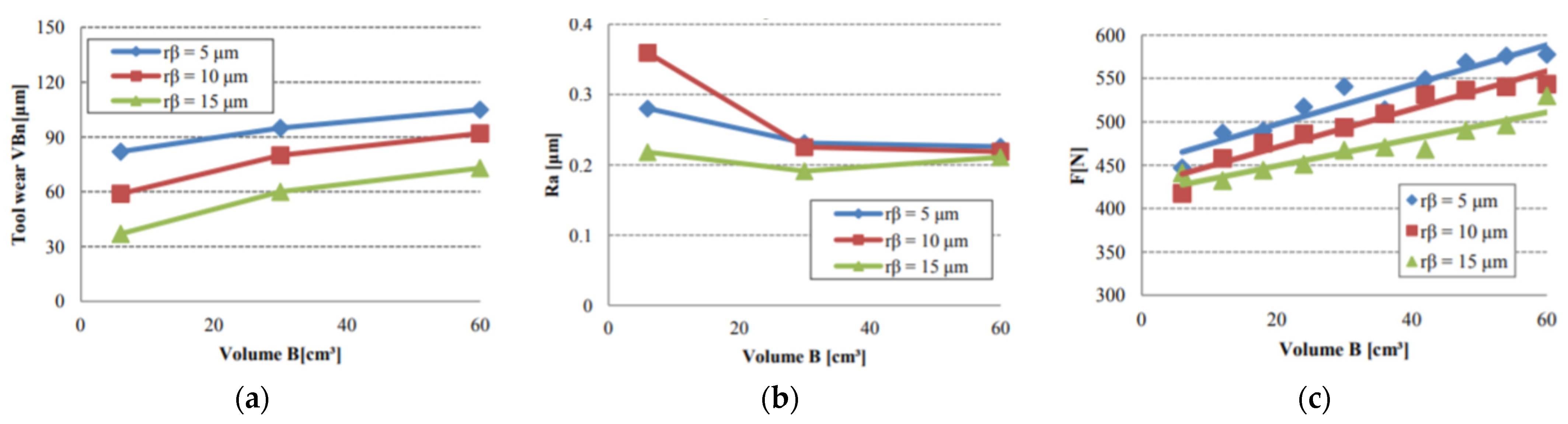
- Denkena, B.; Kohler, J.; Mengasha, M.S. Influence of the cutting edge rounding on the chip formation process: Part 1. Investigation of material flow, process forces, and cutting temperature. Prod. Eng. 2012, 6, 329–338. [Google Scholar] [CrossRef]
- Rech, J.; Yen, Y.-C.; Schaff, M.; Hamdi, H.; Altan, T.; Bouzakis, K. Influence of cutting edge radius on the wear resistance of PM-HSS milling inserts. Wear 2005, 259, 1168–1176. [Google Scholar] [CrossRef]
- Bouzakis, K.-D.; Michailidis, N.; Skordaris, G.; Kombogiannis, S.; Hadjiyiannis, S.; Efstathiou, K.; Erkens, G.; Rambadt, S.; Wirth, I. Effect of the Cutting Edge Radius and its Manufacturing Procedure, on the Milling Performance of PVD Coated Cemented Carbide Inserts. CIRP Ann. 2002, 51, 61–64. [Google Scholar] [CrossRef]
- Chastagner, M.W.; Shih, A. Abrasive Jet Machining for Edge Generation. Trans. NAMRI/SME 2007, 35, 359–366. [Google Scholar]
- Shaffer, W.R. Cutting Tool Edge Preparation; Technical Paper; Society of Manufacturing Engineers: Southfield, MI, USA, 1999; pp. 1–8. [Google Scholar]
- Cselle, T. Influence of Edge Preparation on the Performance of Coated Cutting Tools. In Proceedings of the International Conference on Metallurgical Coatings and Thin Films, San Diego, CA, USA, 28 April–2 May 2007; p. 34. [Google Scholar]
- Cheung, F.; Zhou, Z.; Geddam, A.; Li, K. Cutting edge preparation using magnetic polishing and its influence on the performance of high-speed steel drills. J. Mater. Process. Technol. 2008, 208, 196–204. [Google Scholar] [CrossRef]
- Yussefian, N.; Koshy, P.; Buchholz, S.; Klocke, F. Electro-erosion edge honing of cutting tools. CIRP Ann. 2010, 59, 215–218. [Google Scholar] [CrossRef]
- Aurich, J.C.; Zimmermann, M.; Leitz, L. The preparation of cutting edges using a marking laser. Prod. Eng. 2010, 5, 17–24. [Google Scholar] [CrossRef]
- Vopát, T.; Podhorský, Š; Sahul, M.; Haršáni, M. Cutting edge preparation of cutting tools using plasma discharges in electrolyte. J. Manuf. Process. 2019, 46, 234–240. [Google Scholar] [CrossRef]
- Kuruc, M. Rotary Ultrasonic Machining. Application for Cutting Edge Preparation; Springer: Berlin/Heidelberg, Germany, 2021. [Google Scholar] [CrossRef]
- Vel, L.; Demazeau, G.; Etourneau, J. Cubic Boron Nitride: Synthesis, Physicochemical Properties and Applications. Mater. Sci. Eng. B 1991, 10, 149. [Google Scholar] [CrossRef]
- Wentorf, R.H. Synthesis of the Cubic Form of Boron Nitride. J. Chem. Phys. 1961, 34, 809–812. [Google Scholar] [CrossRef]
- Fukunaga, O. Science and technology in the recent development of boron nitride materials. J. Phys. Condens. Matter 2002, 14, 10979–10982. [Google Scholar] [CrossRef]
- Kawaguchi, M.; Kuroda, S.; Muramatsu, Y. Electronic structure and intercalation chemistry of graphite-like layered material with a composition of BC6N. J. Phys. Chem. Solids 2007, 69, 1171–1178. [Google Scholar] [CrossRef]
- Komatsu, T.; Samedima, M.; Awano, T.; Kakadate, Y.; Fujiwara, S. Creation of Superhard B–C–N Heterodiamond Using an Advanced Shock Wave Compression Technology. J. Mater. Processing Technol. 1999, 85, 69. [Google Scholar] [CrossRef]
- Leichtfried, G. Properties of diamond and cubic boron nitride. In Landolt-Börnstein—Group VIII Advanced Materials and Technologies: Powder Metallurgy Data. Refractory, Hard and Intermetallic Materials 2A2; Springer: Berlin/Heidelberg, Germany, 2002; pp. 118–139. [Google Scholar]
- Tian, Y.; Xu, B.; Yu, D.; Ma, Y.; Wang, Y.; Jiang, Y.; Hu, W.; Tang, C.; Gao, Y.; Luo, K.; et al. Ultrahard nanotwinned cubic boron nitride. Nature 2013, 493, 385–388. [Google Scholar] [CrossRef] [PubMed]
- Halnn Superhard Tools: Advantages of Halnn CBN Inserts Milling Hard Materials. Published on 27 May 2019. Available online: https://www.linkedin.com/pulse/advantages-halnn-cbn-inserts-milling-hard-materials-halnn-tools/ (accessed on 26 July 2022).
- Singh, R.P.; Singhal, S. Rotary Ultrasonic Machining: A Review. In Materials and Manufacturing Processes; Taylor & Francis Group: Oxford, UK, 2016; Volume 31, pp. 1795–1824. ISSN 1042-6914. [Google Scholar]
- Kuruc, M. Machine tool loads in rotary ultrasonic machining of alumina, CBN and synthetic diamond. In Proceedings of the 26th DAAAM International Symposium, Zadar, Croatia, 21–24 October 2015; DAAAM International: Viedeň, Austria, 2015; pp. 519–523, ISBN 978-3-902734-07-5. [Google Scholar]
- Kuruc, M.; Vopát, T.; Peterka, J. Surface roughness of poly-crystalline cubic boron nitride after rotary ultrasonic machining. In Annals of DAAAM and Proceedings of DAAAM Symposium: Collection of Working Papers for 25th DAAAM International Symposium, Vienna, Austria, 26–29 November 2014; Elsevier: Amsterdam, The Netherlands, 2015; Volume 25, ISSN 2304-1382. [Google Scholar]
- Kuruc, M.; Urminský, J.; Necpal, M.; Morovič, L.; Peterka, J. Comparison of machining of poly-crystalline cubic boron nitride by rotary ultrasonic machining and laser beam machining in terms of shape geometry. In Proceedings of the Strojírenská Technologie—Plzeň 2015: 6. Ročník Mezinárodní Konference, Plzeň, Czech Republic, 3–4 February 2015; pp. 122–128, ISBN 978-80-261-0304-2. [Google Scholar]
- Fulemova, J.; Janda, Z. Influence of the Cutting Edge Radius and the Cutting Edge Preparation on Tool Life and Cutting Forces at Inserts with Wiper Geometry. Procedia Eng. 2014, 69, 565–573. [Google Scholar] [CrossRef] [Green Version]


| Cutting Speed vc (m/min) | Feed Rate vf (mm/min) | Depth of Cut ap (µm) | Ultrasonic | |
|---|---|---|---|---|
| Frequency f (kHz) | Amplitude A (µm) | |||
| 400 | 300 | 5 | 21.5 | 10 |
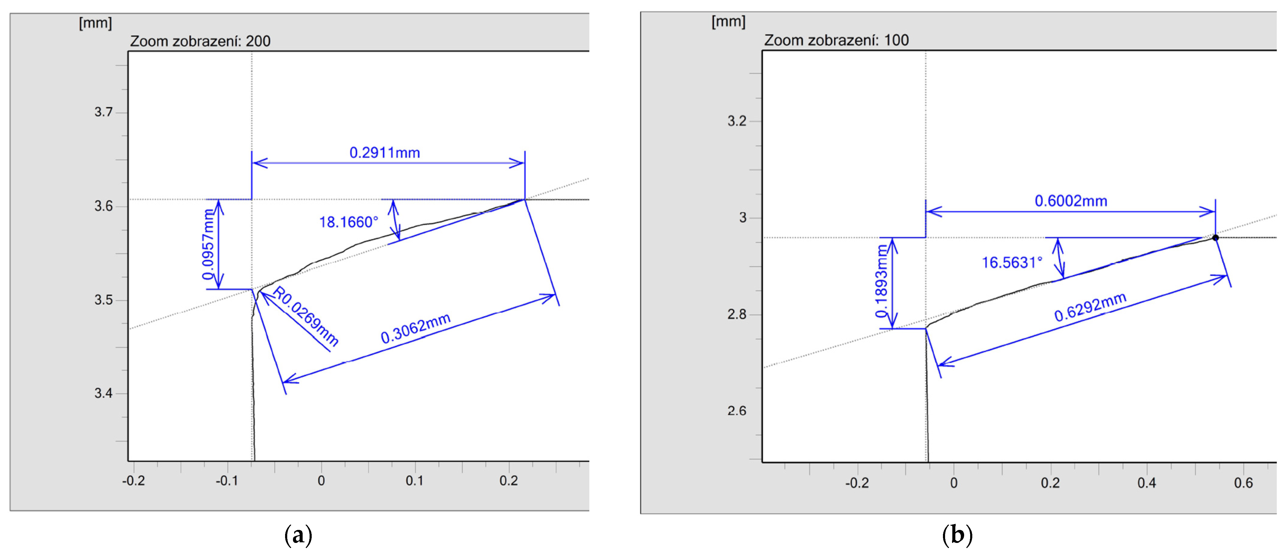
| Edge | Required Dimension | Obtained Dimension | Required Angle | Obtained Angle |
|---|---|---|---|---|
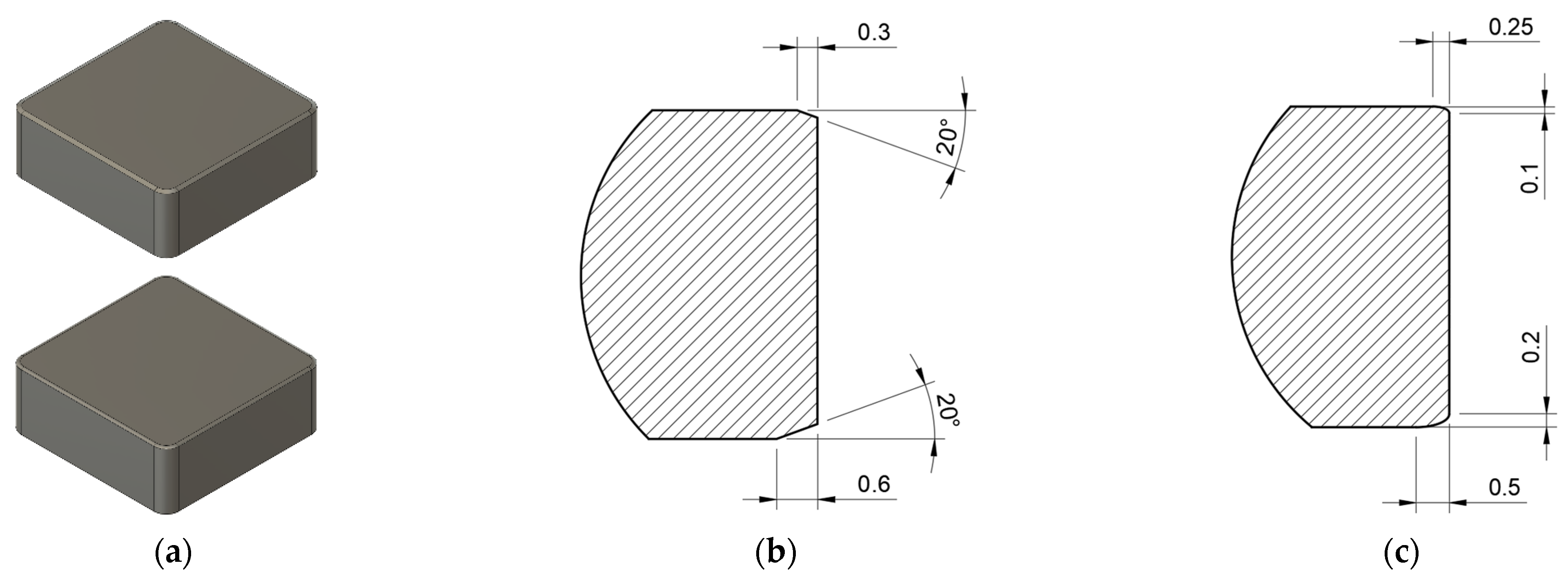
| #1 | 0.3 mm | 0.2911 mm | 20° | 18.1660° |
| #2 | 0.2973 mm | 20.7369° | ||
| #3 | 0.2935 mm | 22.7874° | ||
| #4 | 0.3027 mm | 21.9188° | ||
| #5 | 0.6 mm | 0.5805 mm | 20° | 16.9430° |
| #6 | 0.6002 mm | 16.5631° | ||
| #7 | 0.5904 mm | 17.3275° | ||
| #8 | 0.5778 mm | 17.0797° |
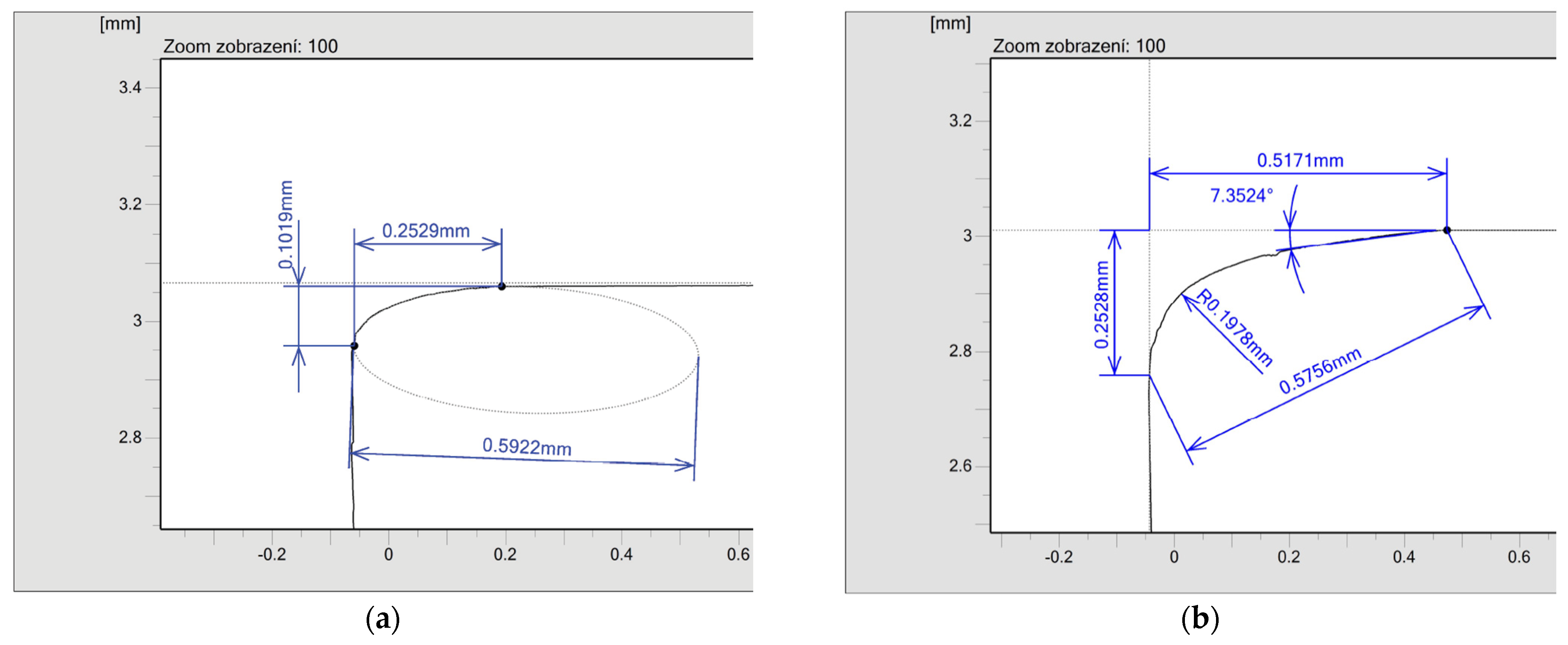
| Edge | Required Dimension | Obtained Dimension | Required Dimension | Obtained Dimension |
|---|---|---|---|---|
| #1 | 0.25 mm | 0.2529 mm | 0.1 mm | 0.1019 mm |
| #2 | 0.2515 mm | 0.0862 mm | ||
| #3 | 0.2455 mm | 0.1027 mm | ||
| #4 | 0.2498 mm | 0.0915 mm | ||
| #5 | 0.5 mm | 0.4652 mm | 0.2 mm | 0.2026 mm |
| #6 | 0.5050 mm | 0.2151 mm | ||
| #7 | 0.5171 mm | 0.2528 mm | ||
| #8 | 0.4789 mm | 0.1986 mm |
| Cutting-Edge Preparation | Mean First Value | Deviation of the First Value | Mean Second Value | Deviation of the Second Value |
|---|---|---|---|---|
| 0.3 mm × 20° | 0.296150 mm | 0.005058 | 20.8998° | 2.008721 |
| 0.6 mm × 20° | 0.587225 mm | 0.010206 | 16.9783° | 0.319300 |
| 0.25 × 0.1 mm | 0.249925 mm | 0.003211 | 0.095575 mm | 0.008068 |
| 0.5 × 0.2 mm | 0.491550 mm | 0.023721 | 0.217275 mm | 0.024704 |
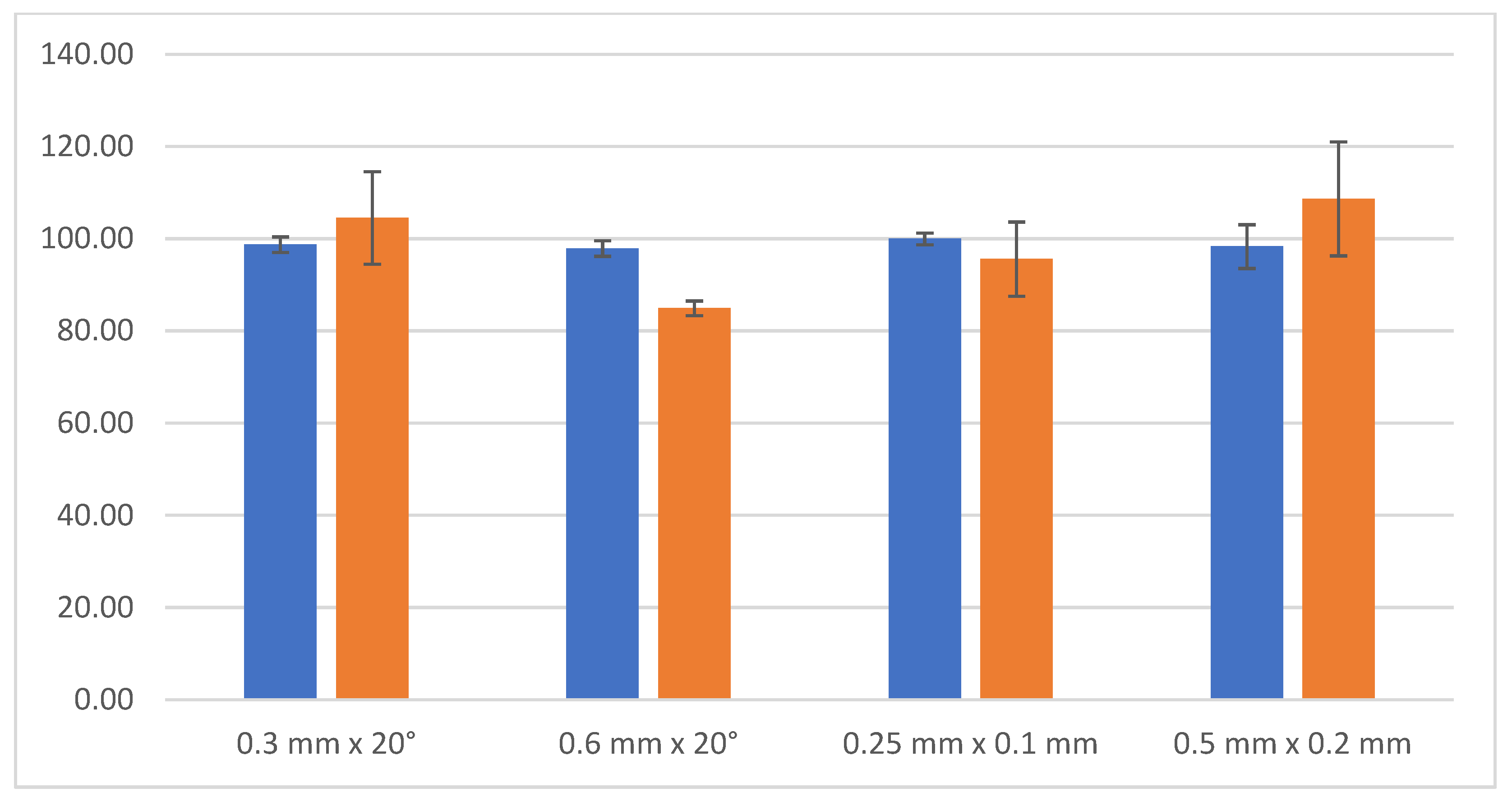
| Cutting-Edge Preparation | Mean First Value | Deviation of the First Value | Mean Second Value | Deviation of the Second Value |
|---|---|---|---|---|
| 0.3 mm × 20° | 98.717% | 1.686% | 104.499% | 10.044% |
| 0.6 mm × 20° | 97.871% | 1.701% | 84.891% | 1.597% |
| 0.25 × 0.1 mm | 99.970% | 1.284% | 95.575% | 8.068% |
| 0.5 × 0.2 mm | 98.310% | 4.744% | 108.638% | 12.352% |
Publisher’s Note: MDPI stays neutral with regard to jurisdictional claims in published maps and institutional affiliations. |
© 2022 by the authors. Licensee MDPI, Basel, Switzerland. This article is an open access article distributed under the terms and conditions of the Creative Commons Attribution (CC BY) license (https://creativecommons.org/licenses/by/4.0/).
Share and Cite
Kuruc, M.; Vopát, T.; Moravčíková, J.; Milde, J. The Precision Analysis of Cutting Edge Preparation on CBN Cutting Inserts Using Rotary Ultrasonic Machining. Micromachines 2022, 13, 1562. https://doi.org/10.3390/mi13101562
Kuruc M, Vopát T, Moravčíková J, Milde J. The Precision Analysis of Cutting Edge Preparation on CBN Cutting Inserts Using Rotary Ultrasonic Machining. Micromachines. 2022; 13(10):1562. https://doi.org/10.3390/mi13101562
Chicago/Turabian StyleKuruc, Marcel, Tomáš Vopát, Jana Moravčíková, and Ján Milde. 2022. "The Precision Analysis of Cutting Edge Preparation on CBN Cutting Inserts Using Rotary Ultrasonic Machining" Micromachines 13, no. 10: 1562. https://doi.org/10.3390/mi13101562