
Two-Step Glass Molding Process for Forming Glass Edges with Obtuse Angles for Mobile Displays

 and
and
Abstract
:1. Introduction
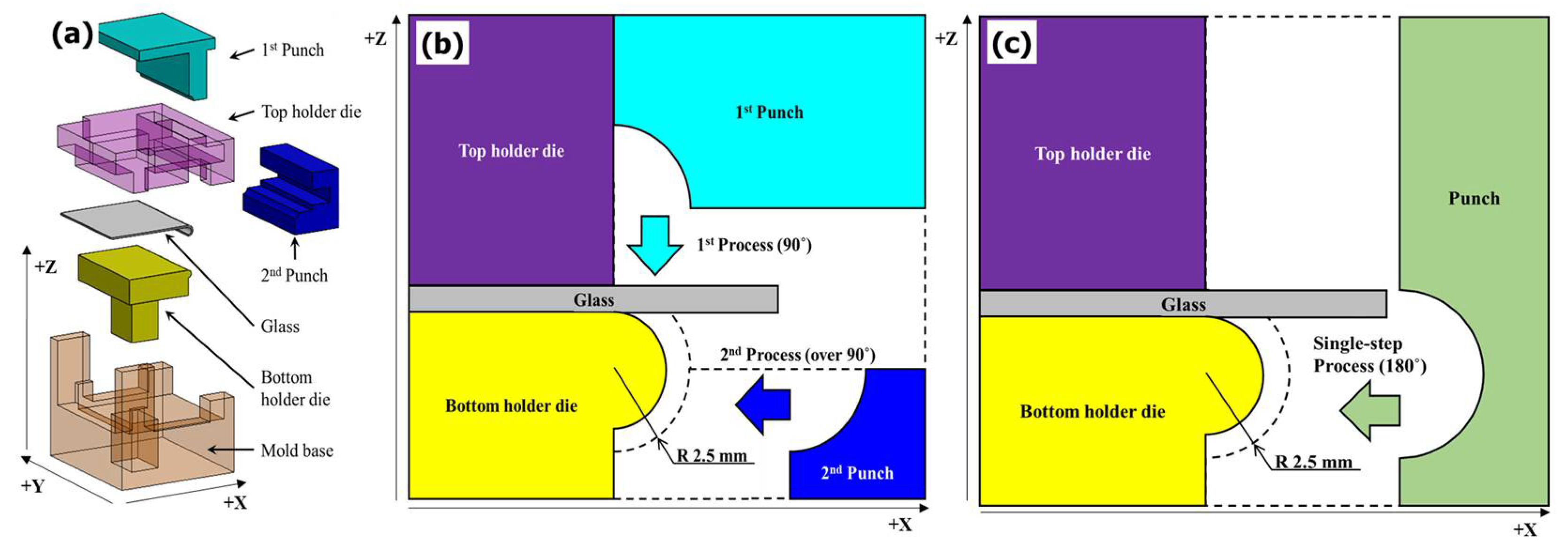
2. Two-Step Glass Hot Forming Processes
3. Analysis of Glass Properties for GMP Analysis
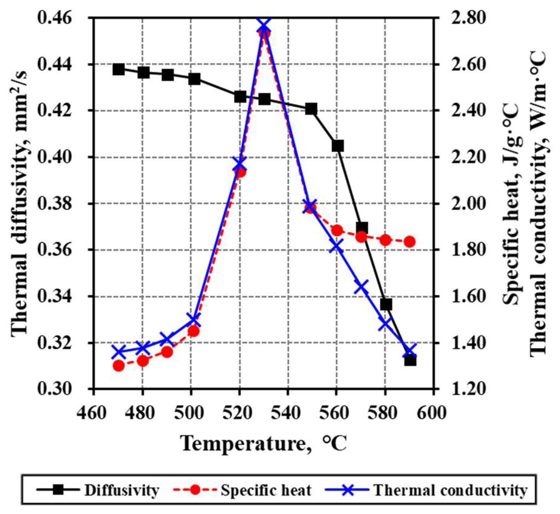
3.1. Temperature-Dependent Behavioral Characteristics of Glass
3.2. Glass for the GMP Process
4. Finite Elemental Analysis of Glass Molding Press
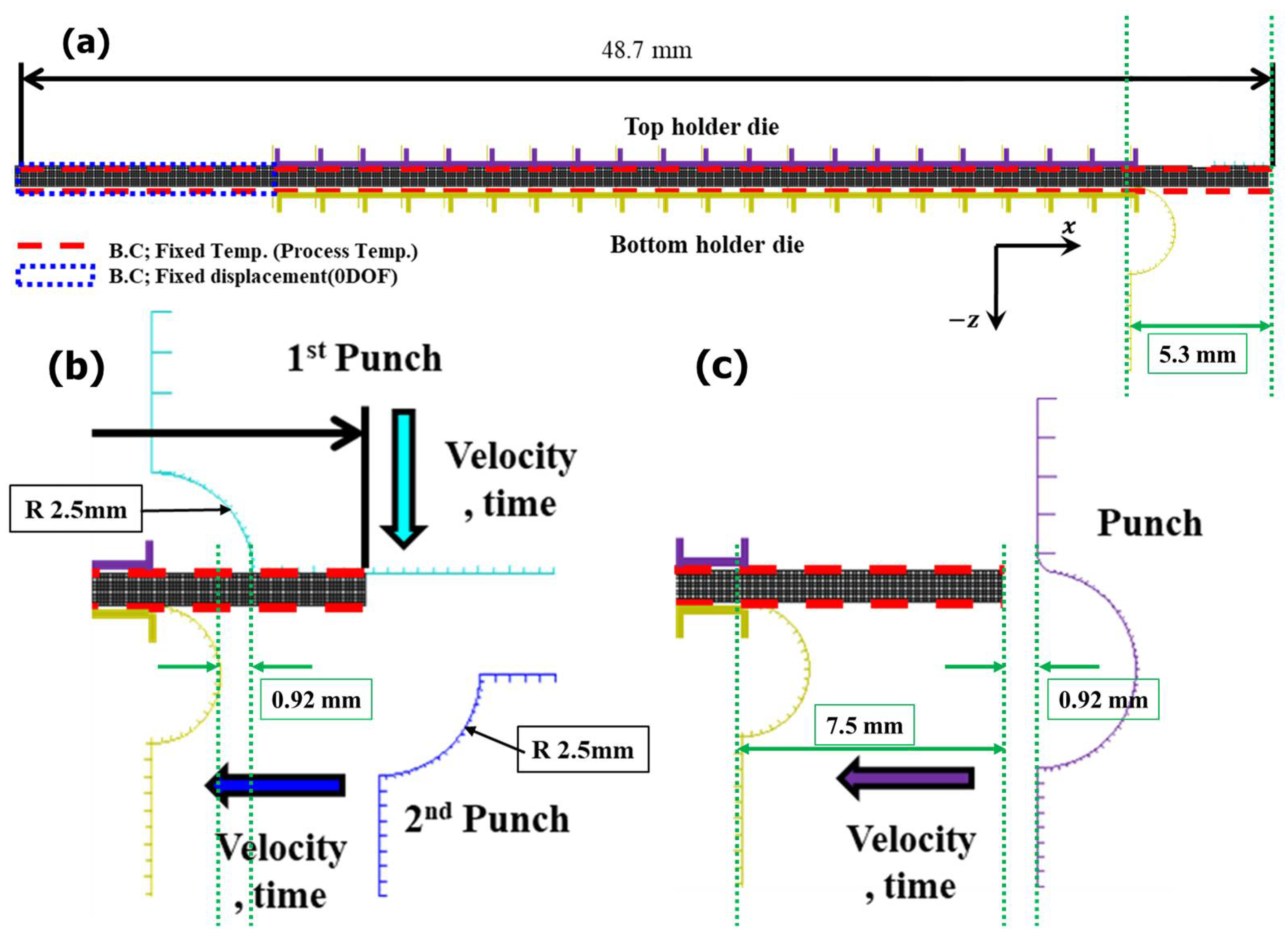
4.1. Analysis Geometry and Condition
4.2. Analysis Results
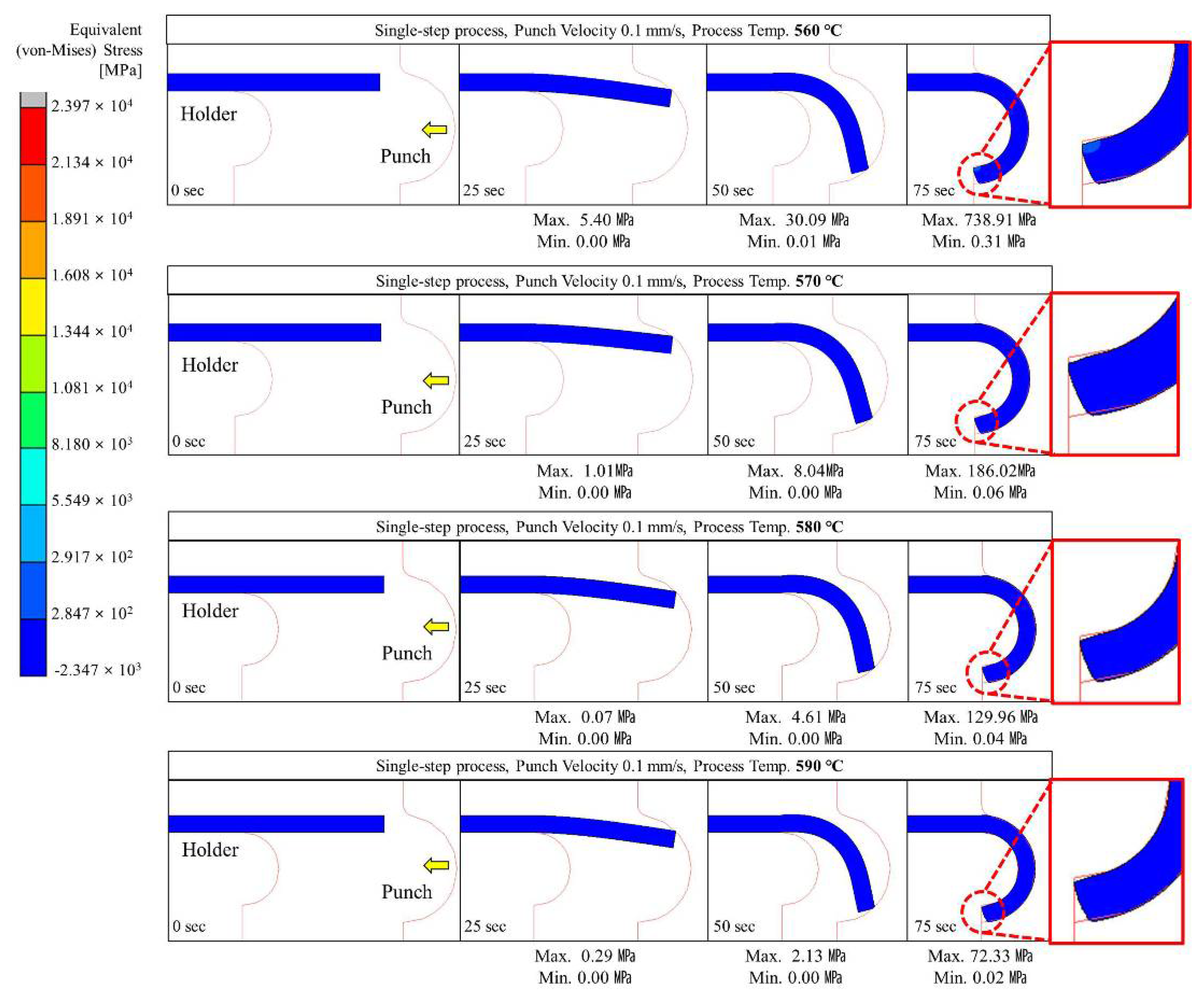
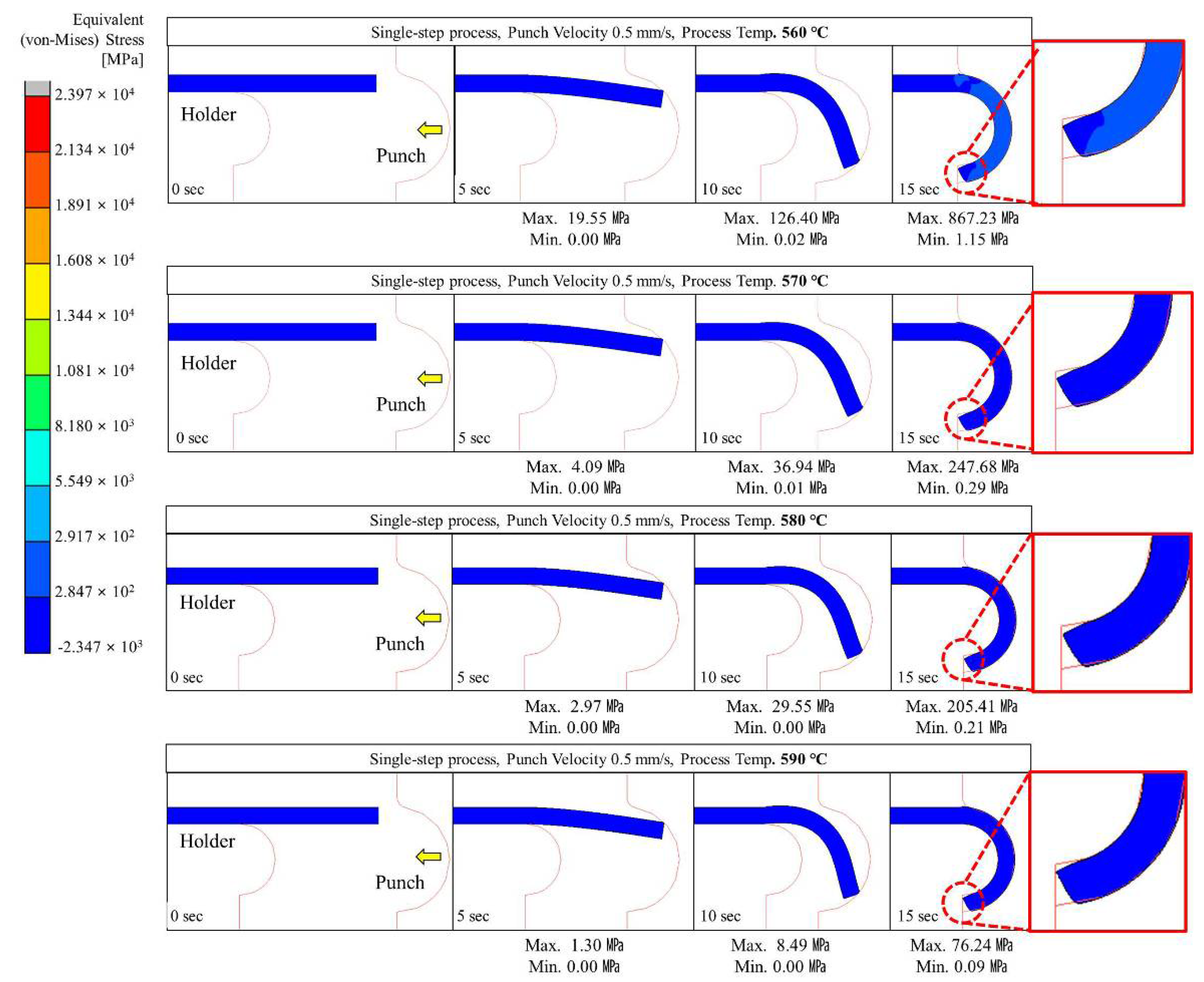
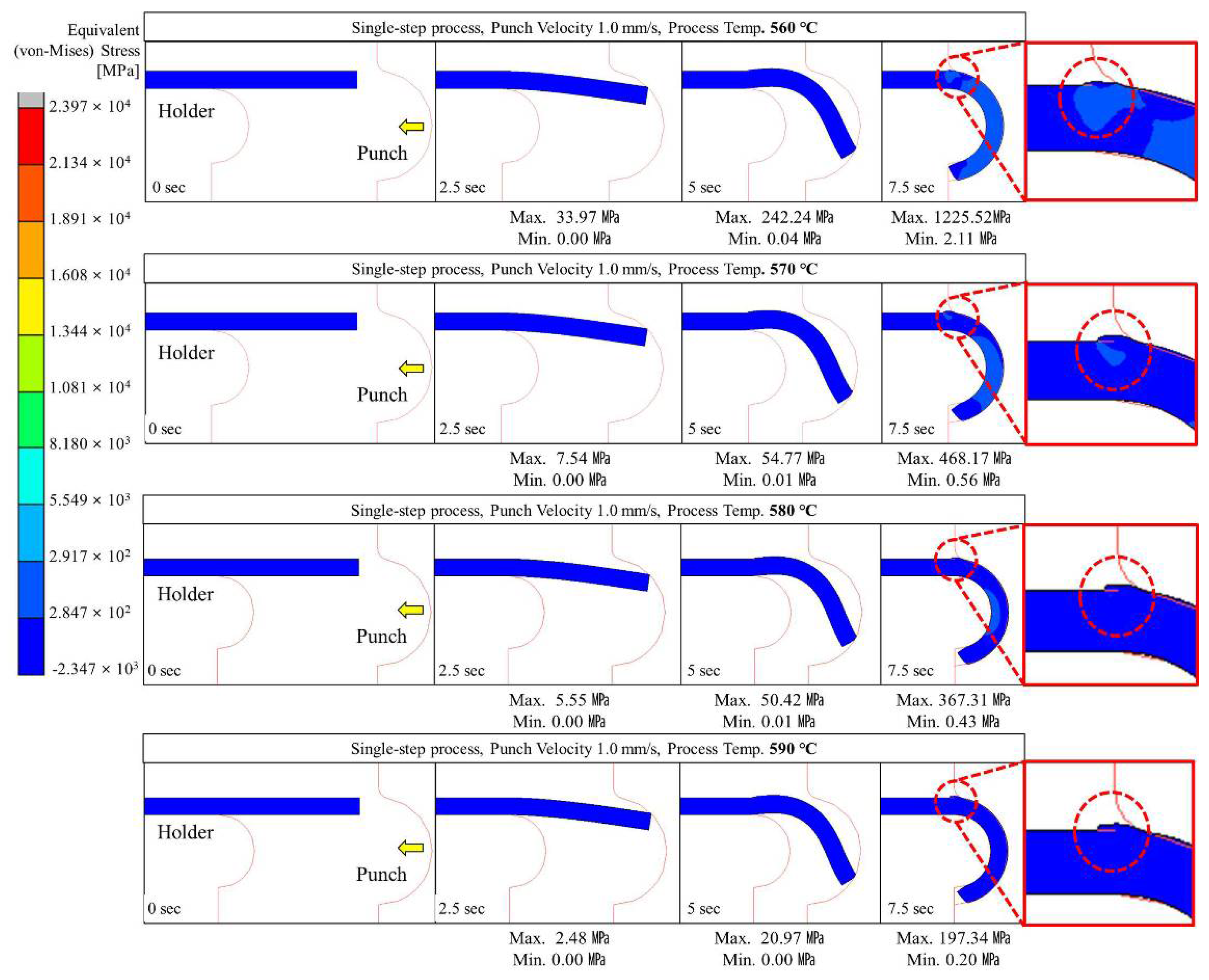
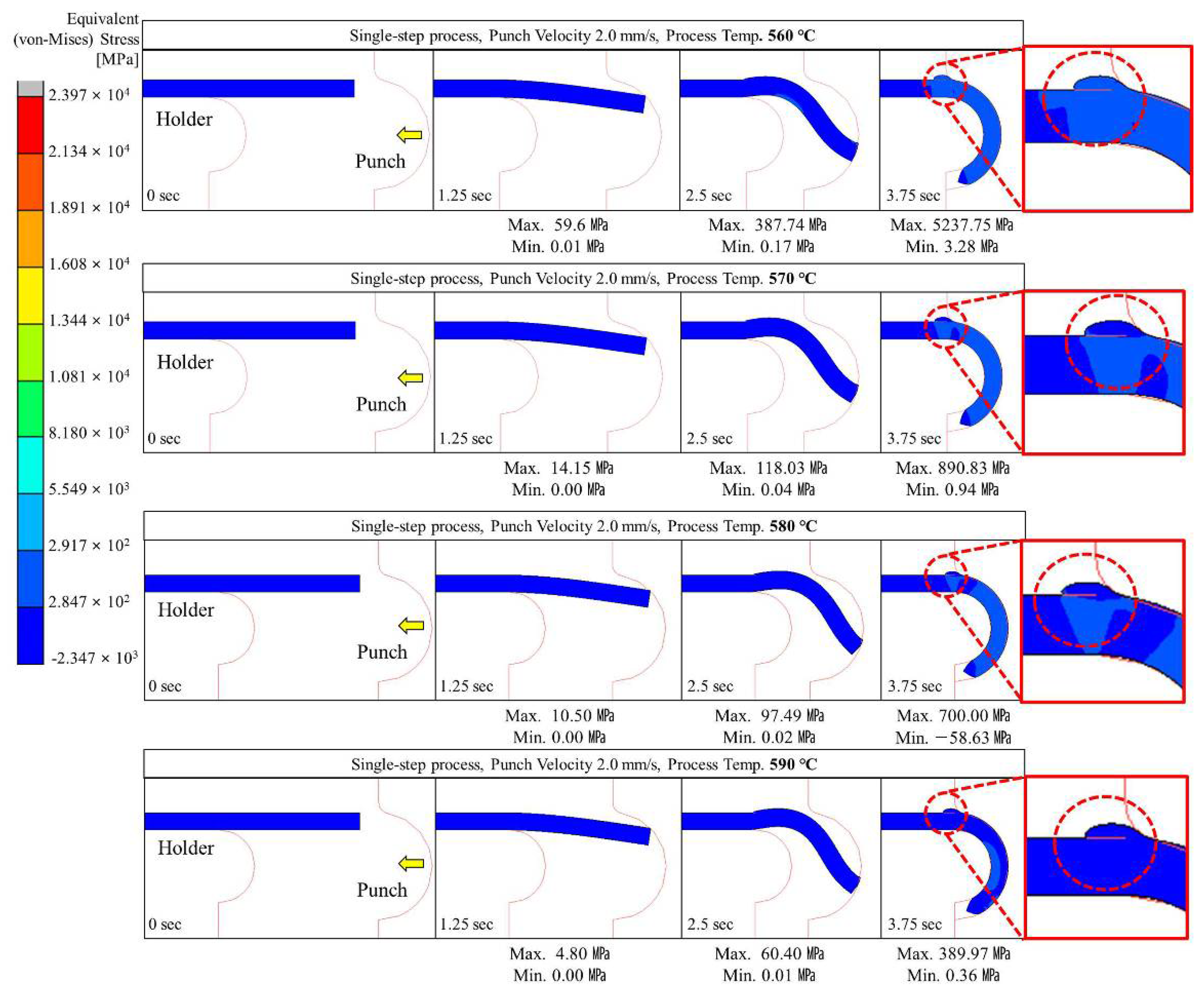
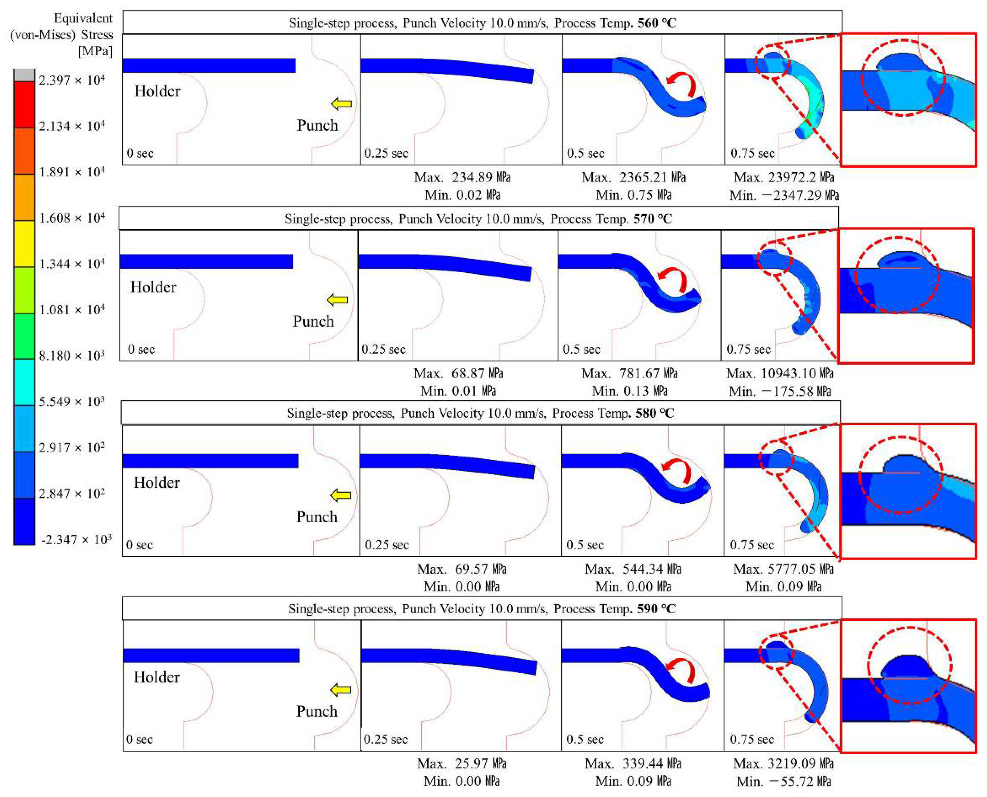
4.2.1. Single-Step Compression Forming (Simultaneous Forming Up to 180°)
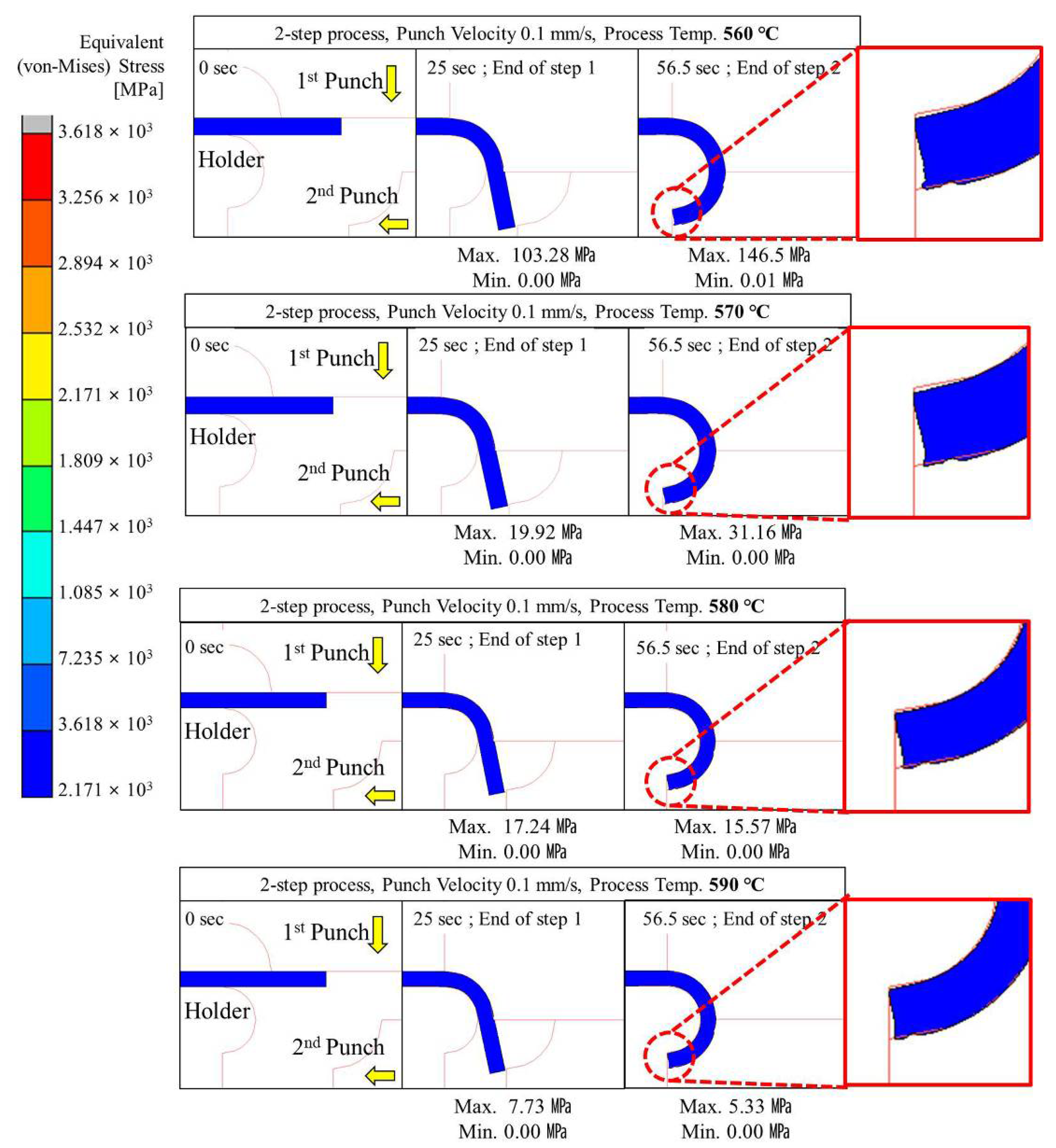
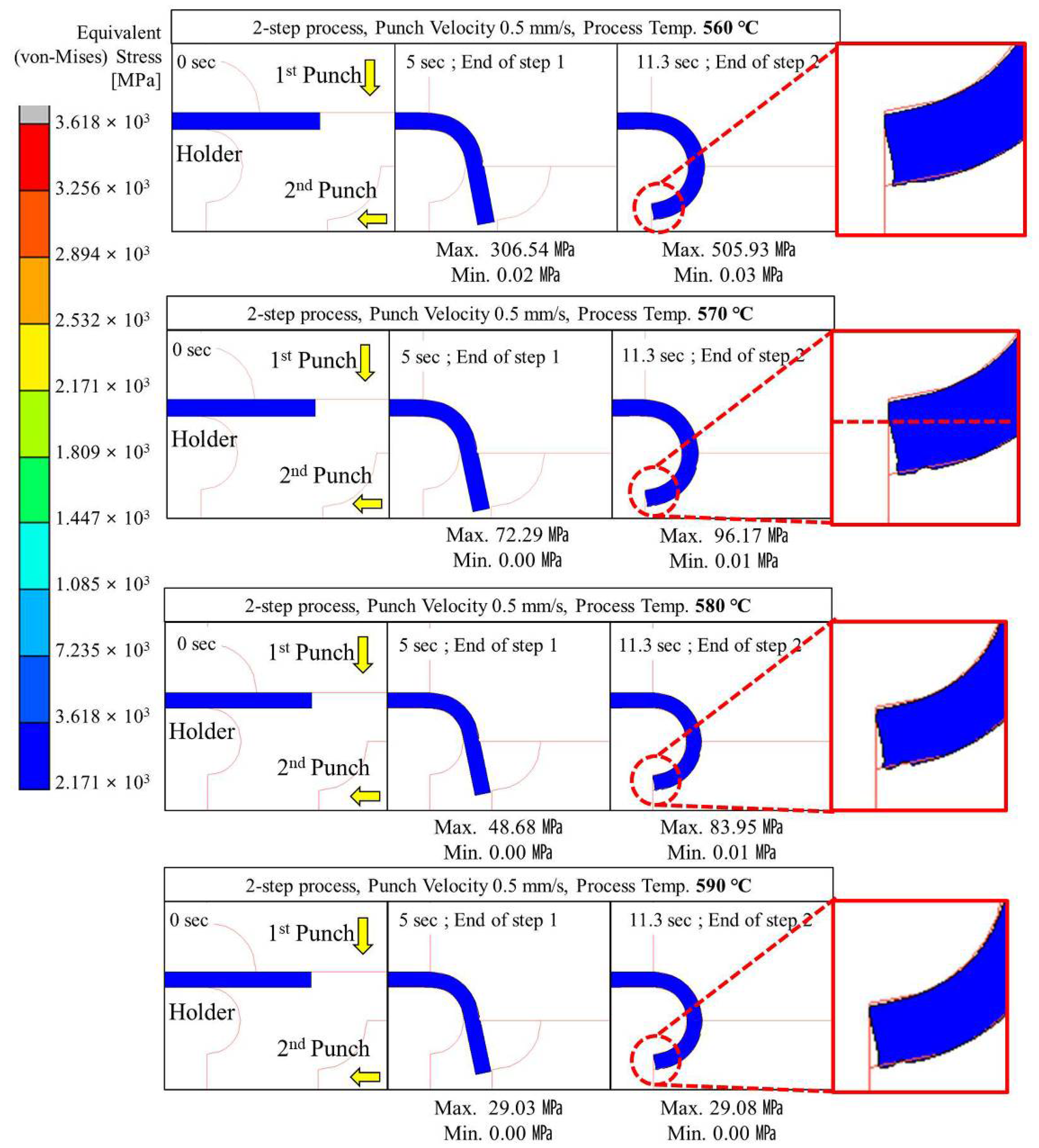
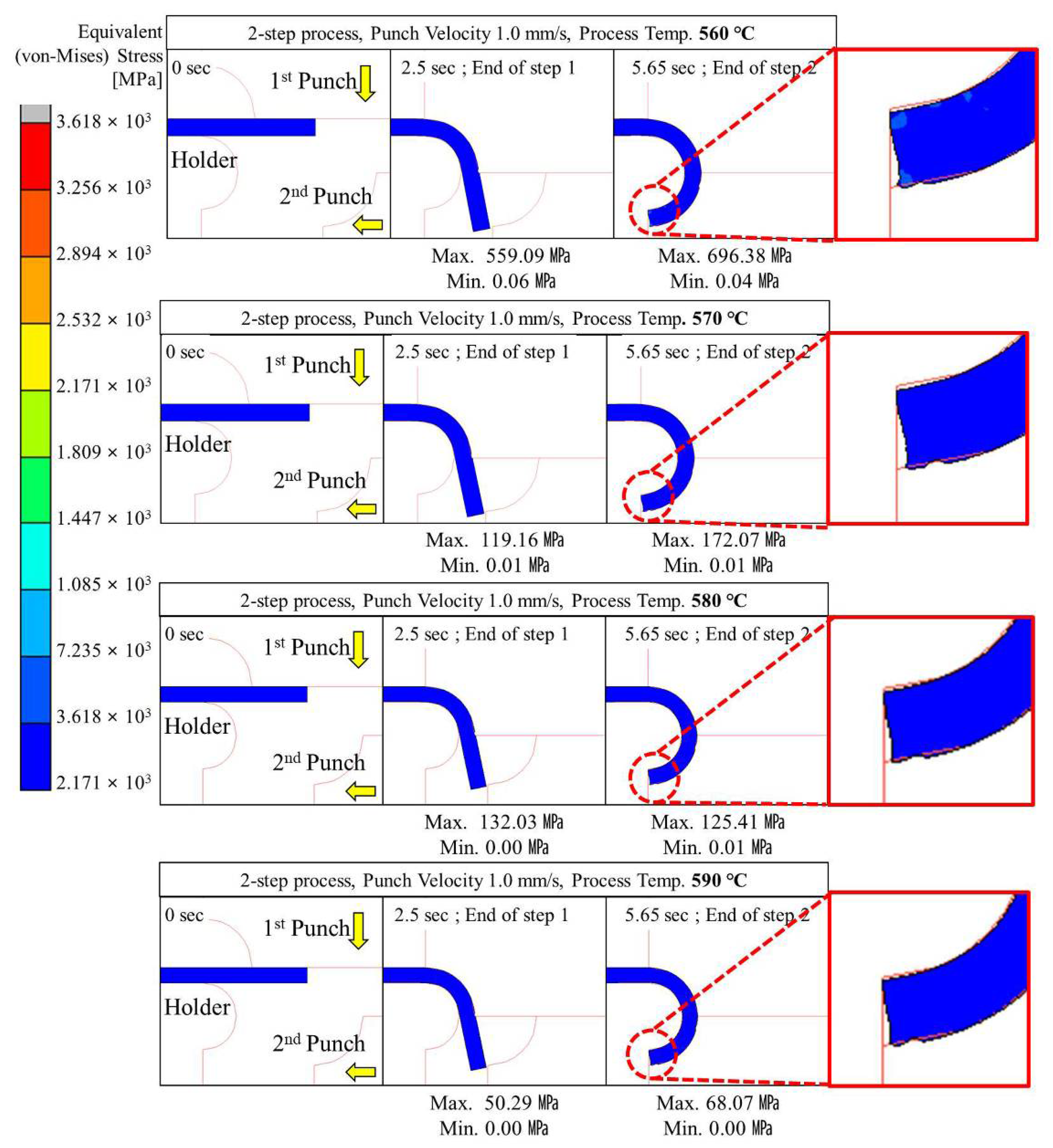
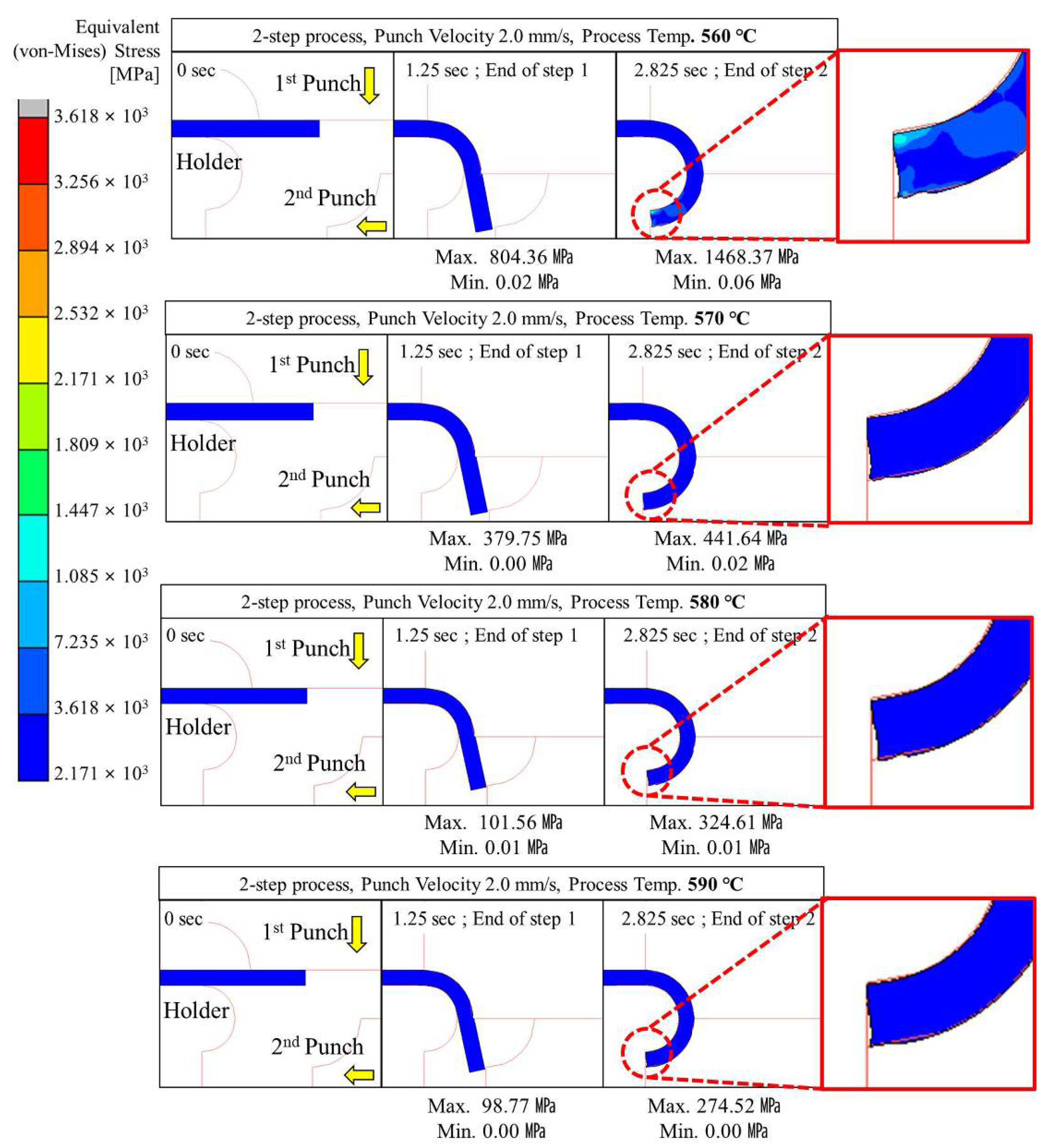
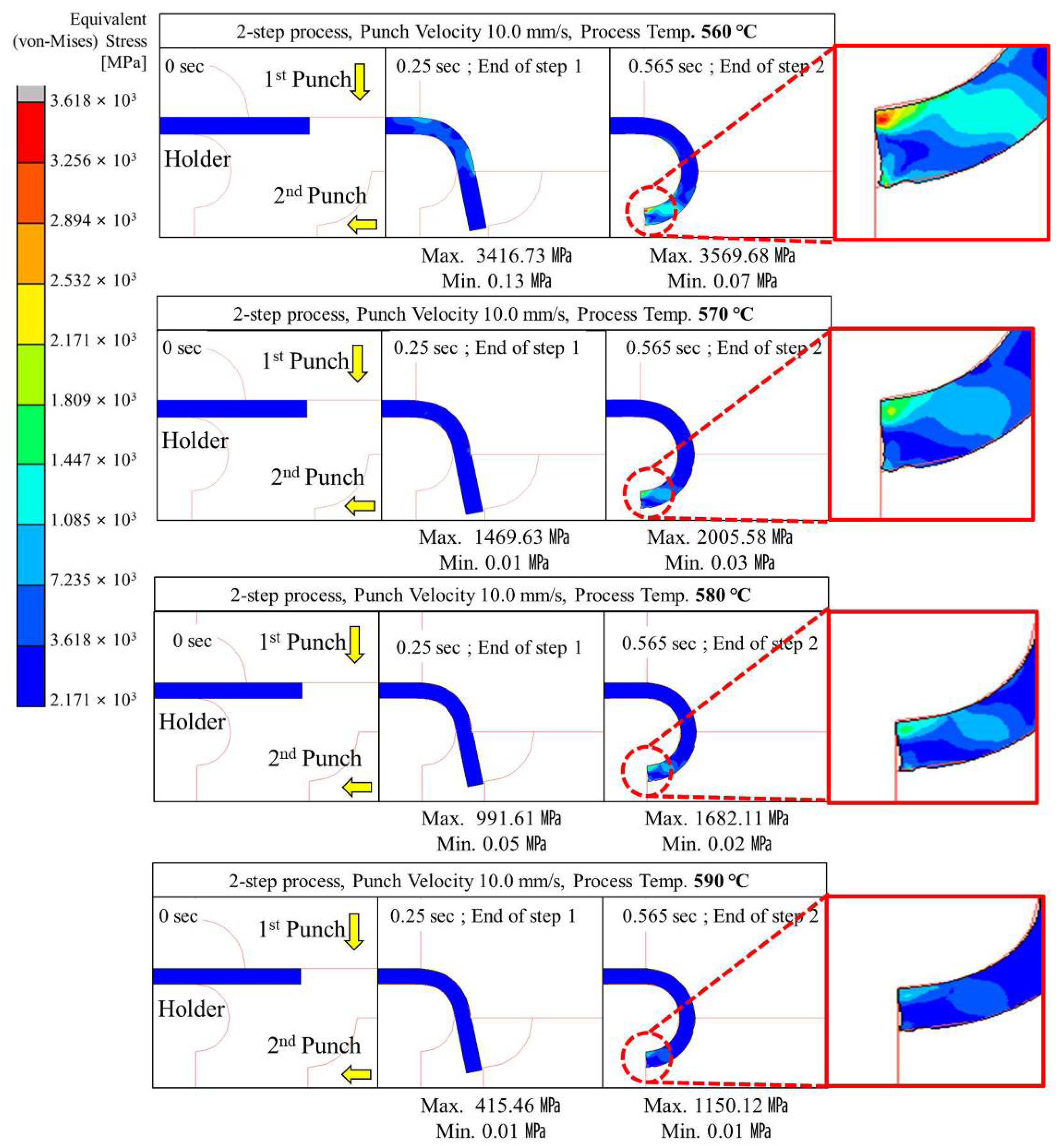
4.2.2. Two-Step Compression Forming (Sequential Forming to 90° and 180°)
5. Experiments
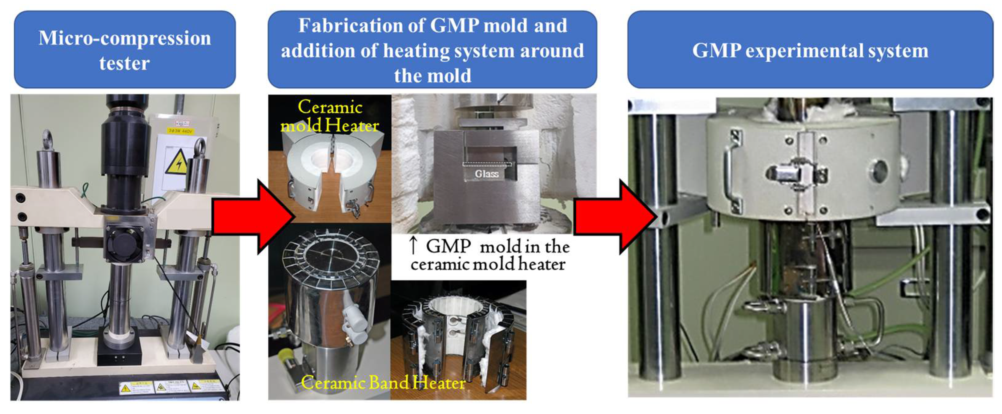
5.1. Equipment
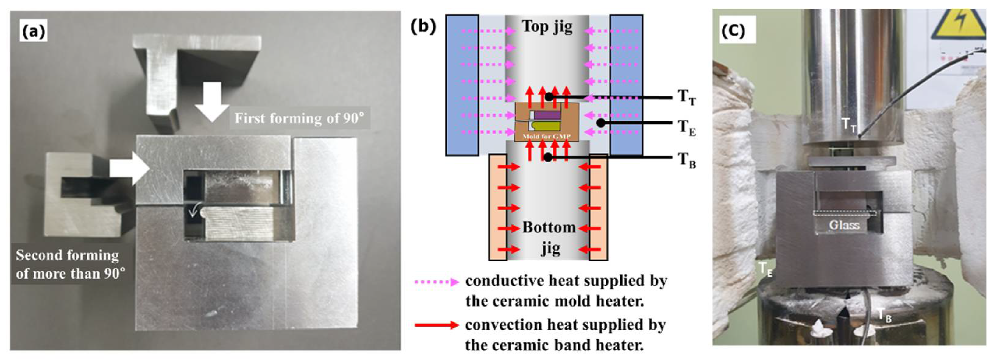
5.2. Experimental Setup
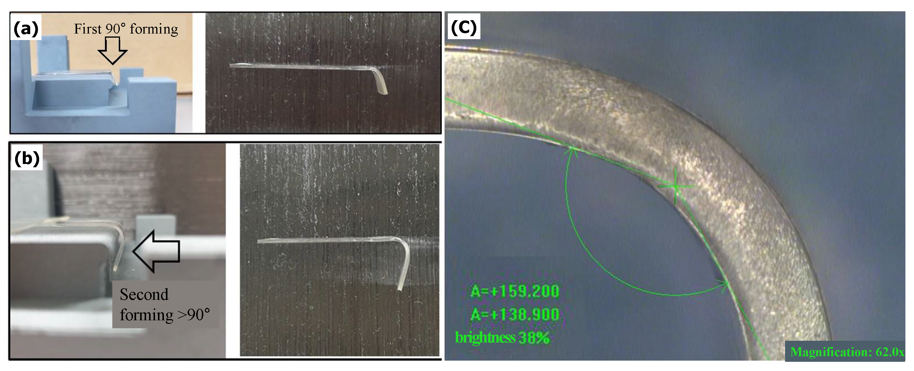
5.3. Experimental Results
6. Conclusions
- (1)
- The FEM simulation results showed that it is possible to form a glass edge with a curvature of 180° without damaging the material and without introducing surface irregularities by applying two-step compression forming with quadrant-shaped (curvature 90° + 90°) punches rather than single-step compression forming with a semi-circular (curvature 180°) punch during the GMP process for curved glass molding.
- (2)
- The optimal conditions for two-step compression forming to form a curved edge with a curvature of 90° or more using glass of 10 mm (width) × 40 mm (length) × 0.8 mm (thickness) were derived using plastic analysis and are as follows: punch speeds of less than 2 mm/s and 10 mm/s at forming temperatures of 560 °C and 570 °C, respectively.
- (3)
- An actual glass forming experiment performed by applying a punch speed of 1 mm/s at a forming temperature of 570 °C resulted in formed glass with a curvature radius of 2.5 mm and a thickness deviation of 30 μm, similar to the analysis results. The curvature, however, was found to be 138.9° instead of 180°. This may be the result of the overestimation of the curvature in the analysis and the spring-back phenomenon occurred in the actual test specimen due to the unremoved residual stress, because the annealing and cooling steps were not properly implemented in the FEM simulation and forming experiments.
- (4)
- This study made it possible to form a curvature edge of more than 90° by only thermoforming a part of the upper and lower mold shapes used to perform the GMP process. This approach obviated the need to apply heat pressing to the entire upper and lower surfaces of the cover glass.
- (5)
- The mold design method that is mainly used in the conventional GMP process cannot apply the undercut structure for molding and extracting the edge surface with a curvature of more than 90°. This study overcame this problem by proposing a mold that can mold cover glass with an edge surface of 90° or more, even if the shape of the top and bottom of the mold does not correspond to the curvature shape of the cover glass to be created.
7. Discussion
Author Contributions
Funding
Institutional Review Board Statement
Informed Consent Statement
Data Availability Statement
Acknowledgments
Conflicts of Interest
References
- Worldwide Smartphone Market Forecast, 2018–2022; Market Intelligence & Consulting Institute (MIC): Taipei, Taiwan, 2018.
- Mawston, N.; Wu, Y.; Sui, L. Strategy Analytics: Global Smartphone Shipments Surge to 340 Million Units, Up +24% YoY in Q1 2021. Strateg. Anal. 2021, 4, 19. [Google Scholar]
- Wang, S.D.C. Curved Glass for Touch Screen Mobile Phone. Glass Enamel. 2015, 43, 25–28. [Google Scholar]
- Rongxin, Y. Discussion on the Curved Screen of Smart Phone. Digit. Commun. World 2019, 5, 277. [Google Scholar]
- Zhang, Z.; Ming, W.; Zhang, Y.; Yin, L.; Xue, T.; Yu, H.; Chen, Z.; Liao, D.; Zhang, G. Analyzing Sustainable Performance on High-Precision Molding Process of 3d Ultra-Thin Glass for Smart Phone. J. Clean. Prod. 2020, 255, 12096. [Google Scholar] [CrossRef]
- Nicholas, D.J.; Boon, J.E. The Generation of High Precision Aspherical Surfaces in Glass by CNC Machining. J. Phys. Appl. Phys. 1981, 14, 593–600. [Google Scholar] [CrossRef]
- Liu, Y.-H.; Huang, F.-S.; Ou, C.-H. Curling Die Set. U.S. Patent US20080039863A1, 14 February 2008. [Google Scholar]
- Liu, S.-J.; Chen, C.-S.; Huang, L.-B.; Yang, R.-J.; Liu, L. Method for Manufacturing Curved Glass Sheet and Mold Employed in the Same. U.S. Patent US8448470B2, 25 May 2013. [Google Scholar]
- Kim, D.-H.; Ku, J.-O.; Choi, K.-J.; Kim, H.-E. Device For Forming Touch Window Glass For Smart Phone. Korea Patent KR10-1260434, 26 April 2013. [Google Scholar]
- Bader, H.; Vollmer, M.; Hochhaus, R.; Mocnik, R.; Brenz, H.-J. Method for Making a Curved Glass-Ceramic Panel By Bending a Green Glass Panel to Be Ceramicized and Apparatus for Performing Said Method. U.S. Patent US20020020192A1, 21 February 2002. [Google Scholar]
- Nieber, A.R.; Tsuda, S. 3D Forming of Glass. U.S. Patent US20160311717A1, 27 October 2016. [Google Scholar]
- Choi, B.-G.; Youn, K.-B. Cover Glass and Manufacturing Method Thereof. U.S. Patent US20190187757A1, 20 June 2019. [Google Scholar]
- Kim, T.-K.; Oh, S.-T.; Choi, J.-C. Electronic Device Including Glass Housing. EU Patent 19195595.4, 21 December 2017. [Google Scholar]
- Hendren, K.J.; Wang, P.X.; Garelli, A.T.; Degner, B.W.; Ligtenberg, C.A.; Mathew, D.C. Electronic Device with Glass Housing Member. U.S. Patent 20210397220, 23 December 2021. [Google Scholar]
- Inews24. (In Korean). Available online: https://m.inews24.com/v/1425283 (accessed on 22 November 2021).
- Prest, C.D.; Russell-Clarke, P.N. Electronic Device with Glass Enclosure. U.S. Patent US20220057885A1, 24 February 2022. [Google Scholar]
- Etnews. (In Korean). Available online: https://m.etnews.com/20220322000115?obj=Tzo4OiJzdGRDbGFzcyI6Mjp7czo3OiJyZWZlcmVyIjtOO3M6NzoiZm9yd2FyZCI7czoxMzoid2ViIHRvIG1vYmlsZSI7fQ%3D%3D (accessed on 22 March 2022).
- Aono, Y.; Negishi, M.; Takano, J. Development of Large Aperture Aspheric Lens with Glass Molding. In Advanced Optical Manufacturing and Testing Technology; Proc. SPIE: Chengdu, China, 2000; Volume 4231, pp. 16–23. [Google Scholar]
- Umetani, M. Manufacturing of Optical Glass Lens by Press-Molding Method. New Glass 1998, 13, 32–37. [Google Scholar]
- Yan, J.; Zhou, T.; Masuda, J.; Kuriyagawa, T. Modeling High-Temperature Glass Molding Process by Coupling Heat Transfer and Viscous Deformation Analysis. Precis. Eng. 2009, 33, 150–159. [Google Scholar] [CrossRef]
- Kim, H.; Cha, D.; Lee, J.; Kim, S.; Kim, J. A Study on Pressing Conditions in the Molding of Aspheric Glass Lenses for Phone Camera Module Using Design of Experiments. J. Korean Inst. Electr. Electron. Mater. Eng. 2007, 20, 720–725. [Google Scholar] [CrossRef]
- Jeong, T.; Park, G.; Kim, D. Effect of the Molding Conditions on Formability in Progressive Glass Molding Press. J. Korean Soc. Technol. Plast. 2009, 18, 633–639. [Google Scholar]
- Su, L.; Wang, F.; He, P.; Dambon, O.; Klocke, F.; Yi, A.Y. An Integrated Solution for Mold Shape Modification in Precision Glass Molding to Compensate Refractive Index Change and Geometric Deviation. Opt. Lasers Eng. 2014, 53, 98–103. [Google Scholar] [CrossRef]
- Cha, D.H.; Park, H.S.; Hwang, Y.; Kim, J.; Kim, H. Experimental Study of Glass Molding Process and Transcription Characteristics of Mold Surface in Molding of Aspheric Glass Lenses. Opt. Rev. 2011, 18, 241–246. [Google Scholar] [CrossRef]
- Wang, T.; Zhou, T.; Chen, J.; Song, L. Study the Formation Process of Cuboid Microprotrusion by Glass Molding Process. Micromachines 2017, 8, 66. [Google Scholar] [CrossRef] [Green Version]
- Zhang, Y.; You, K.; Fang, F. Pre-Compensation of Mold in Precision Glass Molding Based on Mathematical Analysis. Micromachines 2020, 11, 1069. [Google Scholar] [CrossRef] [PubMed]
- Zhou, T.; Liu, X.; Liang, Z.; Liu, Y.; Xie, J.; Wang, X. Recent Advancements in Optical Microstructure Fabrication through Glass Molding Process. Front. Mech. Eng. 2017, 12, 46–65. [Google Scholar] [CrossRef] [Green Version]
- Zhou, T.; Yan, J.; Masuda, J.; Oowada, T.; Kuriyagawa, T. Investigation on Shape Transferability in Ultraprecision Glass Molding Press for Microgrooves. Precis. Eng. 2011, 35, 214–220. [Google Scholar] [CrossRef]
- Li, K.; Xu, G.; Luo, H.; Liu, X.; Gong, F. Glass Flow Behaviors in Micro-Channels during Hot Embossing. Ceram. Int. 2020, 46, 21517–21526. [Google Scholar] [CrossRef]
- Jiang, K.; Li, K.; Xu, G.; Gong, F.; Wu, X.; Diao, D.; Zhu, L. A Novel and Flexible Processing for Hot Embossing of Glass Microfluidic Channels. Ceram. Int. 2021, 47, 1447–1455. [Google Scholar] [CrossRef]
- Asgar, M.A.; Kim, J.; Haq, M.R.; Kim, T.; Kim, S.-M. A Comprehensive Review of Micro/Nano Precision Glass Molding Molds and Their Fabrication Methods. Micromachines 2021, 12, 812. [Google Scholar] [CrossRef]
- Zhou, T.; Zhu, Z.; Liu, X.; Liang, Z.; Wang, X. A Review of the Precision Glass Molding of Chalcogenide Glass (ChG) for Infrared Optics. Micromachines 2018, 9, 337. [Google Scholar] [CrossRef] [Green Version]
- Wang, T.; Chen, J.; Zhou, T.; Song, L. Fabricating Microstructures on Glass for Microfluidic Chips by Glass Molding Process. Micromachines 2018, 9, 269. [Google Scholar] [CrossRef] [Green Version]
- Jang, H.; Haq, M.R.; Ju, J.; Kim, Y.; Kim, S.-M.; Lim, J. Fabrication of All Glass Bifurcation Microfluidic Chip for Blood Plasma Separation. Micromachines 2017, 8, 67. [Google Scholar] [CrossRef] [Green Version]
- Kuang, R.; Yang, P.; Liu, R.; Shan, X.; Wu, Y.; Li, G.; Liu, M. Analysis of the Variation in Surface Roughness of a Glass Sheet After Hot Bending. Glass Technol. Eur. J. Glass Sci. Technol. 2015, 56, 214–220. [Google Scholar] [CrossRef]
- He, W.; Chen, Z.; Ming, W.; Du, J.; Cao, Y.; Ma, J.; Wei, A. Multi-Objective Optimization of Glass Multi-Station Bending Machining for Smartphone Curved Screen. J. Braz. Soc. Mech. Sci. Eng. 2019, 41, 476. [Google Scholar] [CrossRef]
- Na, J.W.; Rhim, S.H.; Oh, S.I.; Jeon, B.H. Finite Element Analysis of Glass Lens Forming Process Using Open Die. Trans. Mater. Proc. 2003, 12, 296–301. [Google Scholar] [CrossRef] [Green Version]
- SUMITA Optical Glass, Inc.; Optical Glass Materials. Available online: https://www.sumita-opt.co.jp/en/products/optical.html (accessed on 13 June 2022).
- Jang, S.H.; Kang, J.J.; Shin, K.H.; Jung, W.C.; Heo, Y.M.; Jung, T.S. Study on the Aspheric Glass Lens Forming Simulation in the Progressive GMP Process. In Proceedings of the Korean Society for Technology of Plasticity in Spring; The Korean Society for Technology of Plasticity: Seoul, Korea, 2008; pp. 539–542. [Google Scholar]
- Saha, P.K. Aluminum Extrusion Technology; ASM International®: Materials Park, OH, USA, 2000; pp. 8–27. [Google Scholar]
- Timoshenko, S.P.; Gere, J.M. Theory of Elastic Stability, 2nd ed.; McGraw-Hill: New York, NY, USA, 1961. [Google Scholar]
- Chang, S.H.; Lee, Y.M.; Jung, T.S.; Kang, J.J.; Hong, S.K.; Shin, G.H.; Heo, Y.M. Simulation of an Aspheric Glass Lens Forming Behavior in Progressive GMP Process. AIP Conf. Proc. 2007, 908, 1055–1060. [Google Scholar]
- Chang, S.H.; Heo, Y.M.; Shin, G.H.; Lee, Y.M.; Kang, J.J.; Jung, T.S. An Experimental Study on Flow Characteristics of PBK-40 for Glass Molding Press Simulation. Key Eng. Mater. 2008, 364–366, 476–481. [Google Scholar]


| Category | Properties | Unit | Value |
|---|---|---|---|
| Thermal | Transformation Point | Tg (°C) | 501 |
| Yielding Point | At (°C) | 549 | |
| Thermal Expansion | 100–300 °C (10−6/°C) | 7.3 | |
| Mechanical | Young’s Modulus | E (GPa) | 799 |
| Modulus of Rigidity | G (GPa) | 325 | |
| Poisson’s Ratio | σ | 0.229 | |
| Other | Specific Gravity | s.g | 2.39 |
| Analysis Condition | ||
|---|---|---|
| Condition | Single-Step Process | 2-Step Process |
| Initial/process temperature on glass and die and punch, °C | 560/570/580/590 °C | |
| Boundary condition |
| |
Mold moving speed (mm/s) |
|
|
| K | 838.67 (@560 °C)/427.4 (@570 °C)/213.3 (@580 °C)/104.2 (@590 °C) | |
| M | 0.794 (@560 °C)/0.853 (@570 °C)/0.893 (@580 °C)/0.912 (@580 °C) | |
| Coefficient of friction | 1 | |
| Temperature (°C)/Punch Speed (mm/s) | Single-Step Compression Process | 2-Step, Compression Process | ||||||||
|---|---|---|---|---|---|---|---|---|---|---|
| 0.1 | 0.5 | 1 | 2 | 10 | 0.1 | 0.5 | 1 | 2 | 10 | |
| 560 | 738.91 | 867.23 | 1225.52 | 5237.75 | 23,972.2 | 146.50 | 505.93 | 616.38 | 1468.37 | 3569.68 |
| 570 | 186.02 | 247.68 | 468.17 | 9808.83 | 10,943.1 | 31.16 | 96.17 | 172.07 1 | 441.64 | 2005.58 |
| 580 | 129.96 | 205.41 | 367.31 | 700.00 | 5777.05 | 15.57 | 83.95 | 125.41 | 324.61 | 1682.11 |
| 590 | 72.33 | 76.24 | 197.34 | 389.97 | 3219.07 | 5.33 | 29.08 | 68.07 | 274.52 | 1150.12 |
| Measuring Position | 2-Step Process (Dimension: mm) | ||||||||
|---|---|---|---|---|---|---|---|---|---|
| 570 °C | 560 °C | ||||||||
| Pt.1 | Pt.2 | Pt.3 | Avg. (L-L0) | Pt.1 | Pt.2 | Pt.3 | Avg. (L-L0) | ||
 | 0.1 | 0.771 | 0.767 | 0.758 | 0.035 | 0.768 | 0.765 | 0.758 | 0.036 |
| 0.5 | 0.770 | 0.768 | 0.764 | 0.033 | 0.772 | 0.765 | 0.763 | 0.033 | |
| 1 | 0.773 | 0.768 | 0.762 | 0.032 | 0.771 | 0.765 | 0.767 | 0.032 | |
| 2 | 0.769 | 0.765 | 0.785 | 0.027 | 0.769 | 0.766 | 0.763 | 0.034 | |
| 10 | 0.774 | 0.766 | 0.782 | 0.026 | 0.773 | 0.764 | 0.775 | 0.029 | |
| Measuring Position | (Dimension: μm) | Ra | Rz |
|---|---|---|---|
 | Before forming | 0.31 | 1.88 |
| After 2-step process | 2.435 | 30.211 |
Publisher’s Note: MDPI stays neutral with regard to jurisdictional claims in published maps and institutional affiliations. |
© 2022 by the authors. Licensee MDPI, Basel, Switzerland. This article is an open access article distributed under the terms and conditions of the Creative Commons Attribution (CC BY) license (https://creativecommons.org/licenses/by/4.0/).
Share and Cite
Park, J.; Chang, S.; Lee, D.; Lee, H.; Kang, B.; Kim, J. Two-Step Glass Molding Process for Forming Glass Edges with Obtuse Angles for Mobile Displays. Micromachines 2022, 13, 1032. https://doi.org/10.3390/mi13071032
Park J, Chang S, Lee D, Lee H, Kang B, Kim J. Two-Step Glass Molding Process for Forming Glass Edges with Obtuse Angles for Mobile Displays. Micromachines. 2022; 13(7):1032. https://doi.org/10.3390/mi13071032
Chicago/Turabian StylePark, Jeongyeon, Sungho Chang, Dongwon Lee, Hyeonhwa Lee, Bongchul Kang, and Jongsu Kim. 2022. "Two-Step Glass Molding Process for Forming Glass Edges with Obtuse Angles for Mobile Displays" Micromachines 13, no. 7: 1032. https://doi.org/10.3390/mi13071032