
Analysis of Tool Wear and Roughness of Graphite Surfaces Machined Using MCD and NCD-Coated Ball Endmills

Abstract
:1. Introduction
2. Experimental Setup
2.1. Preparation of Workpiece and Diamond-Coated Tool
2.1.1. High-Purity Graphite Workpiece
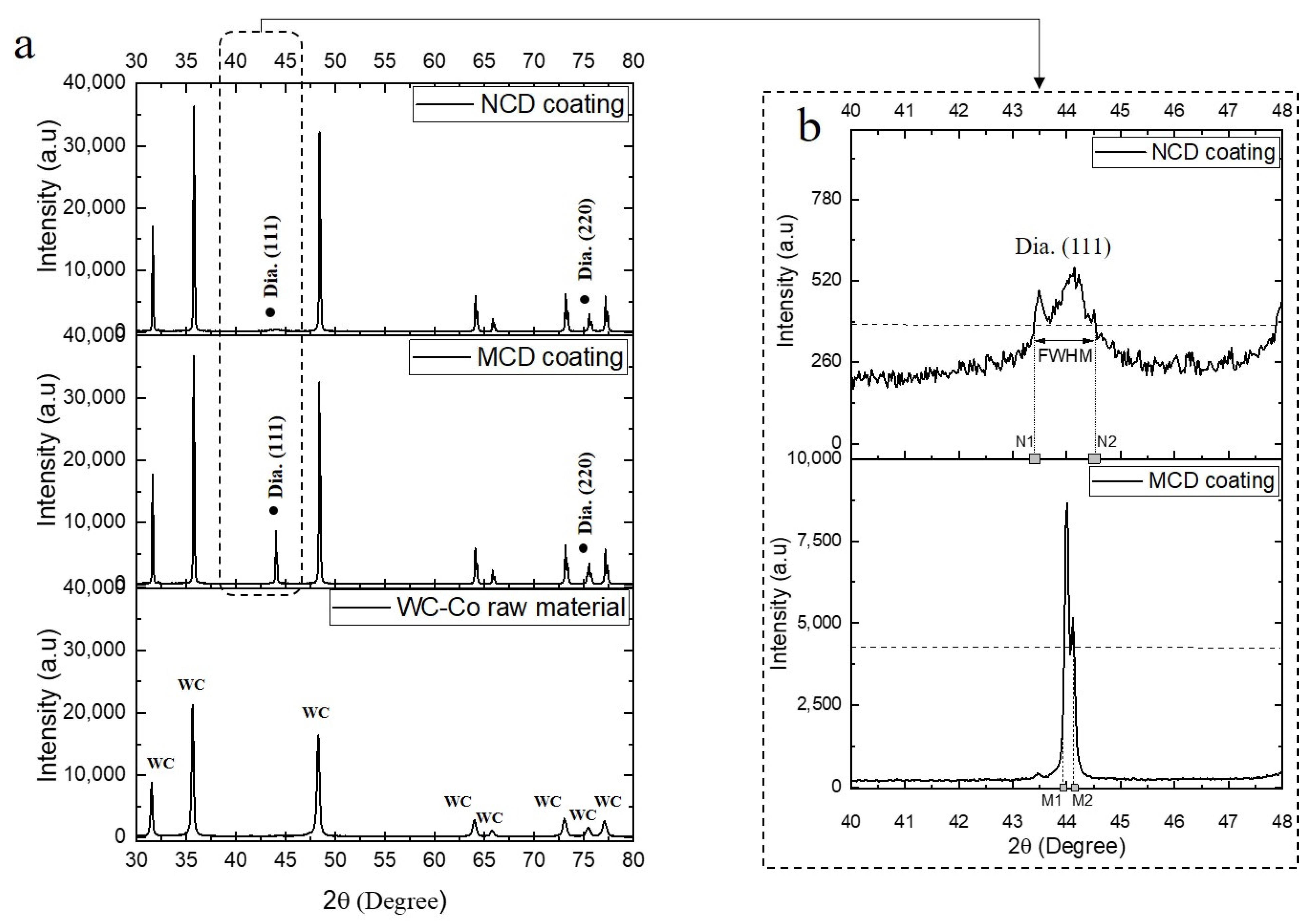
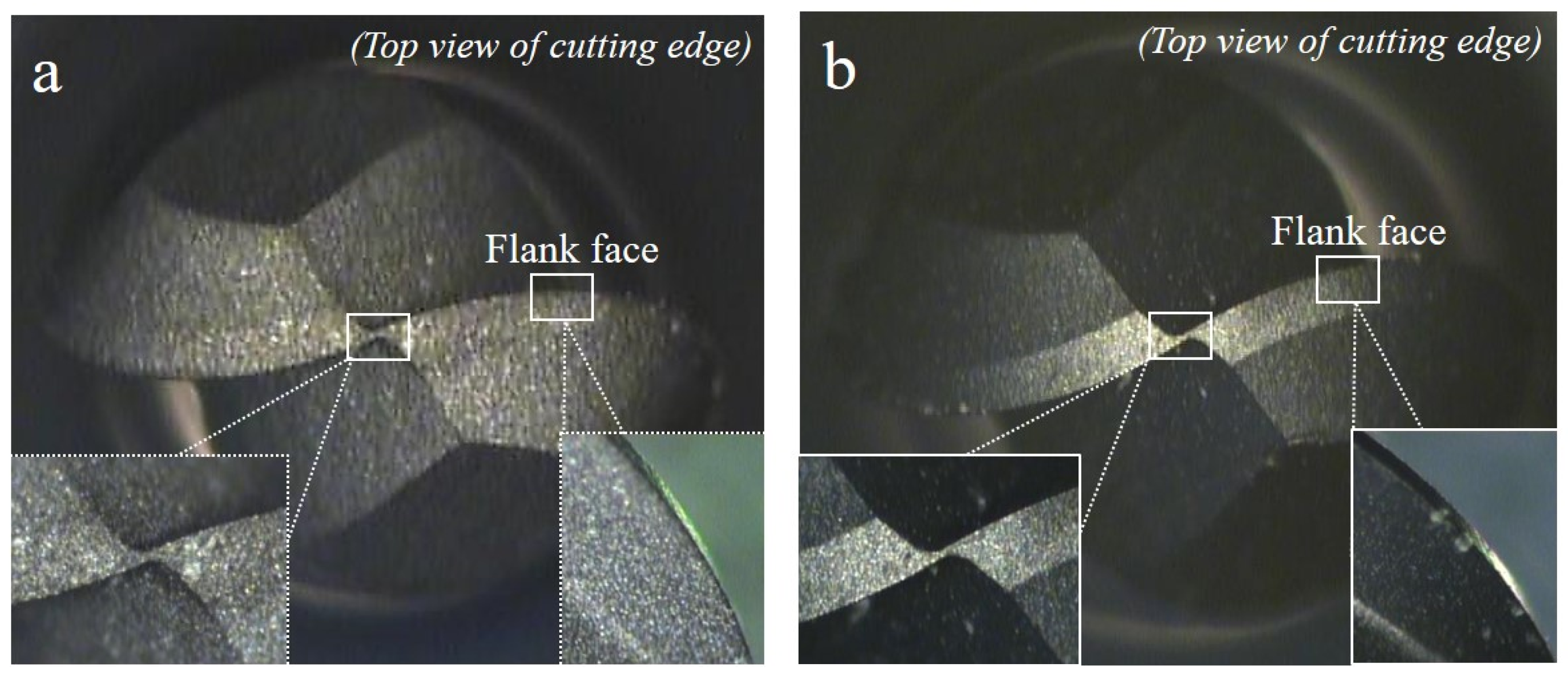
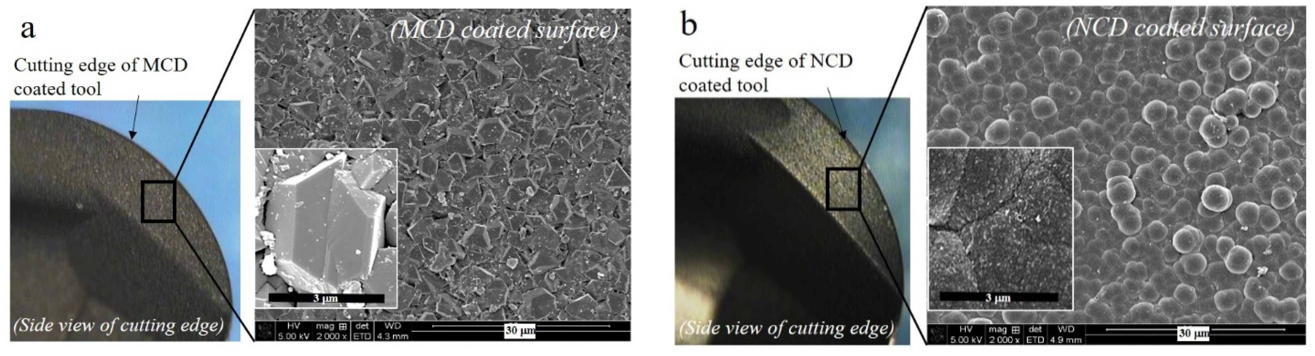
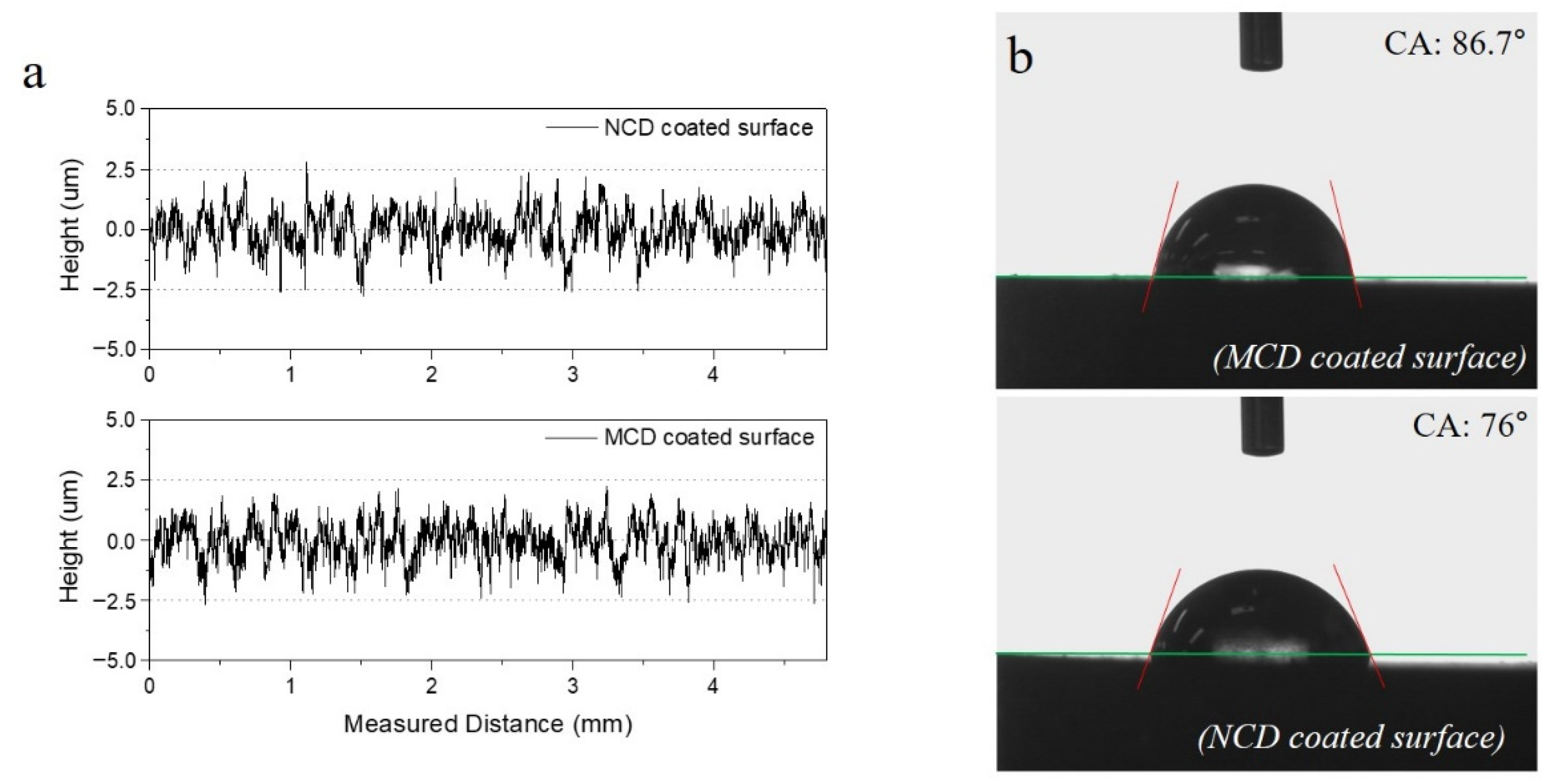
2.1.2. Diamond-Coated Endmill Tool
2.2. Measurement Equipment
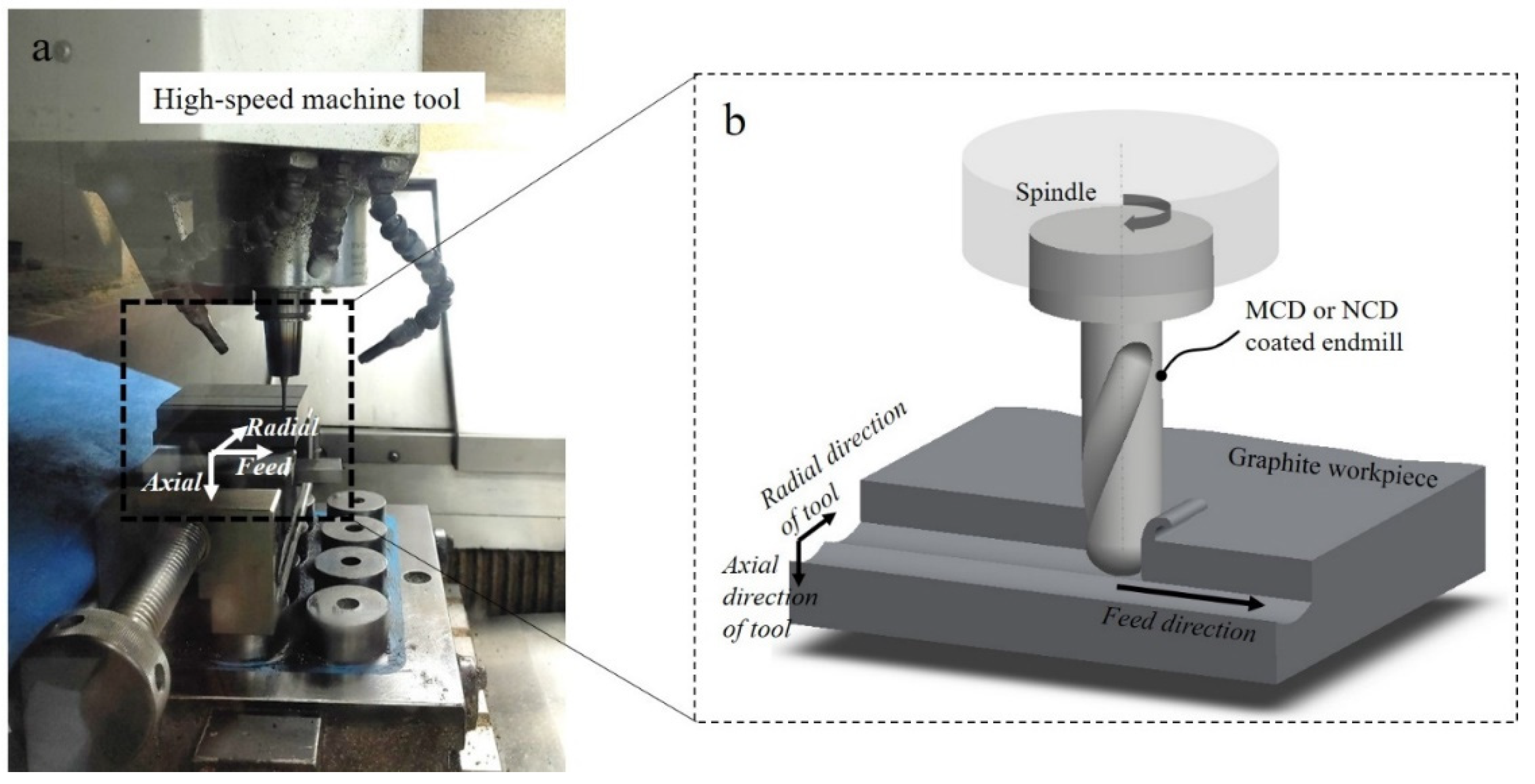
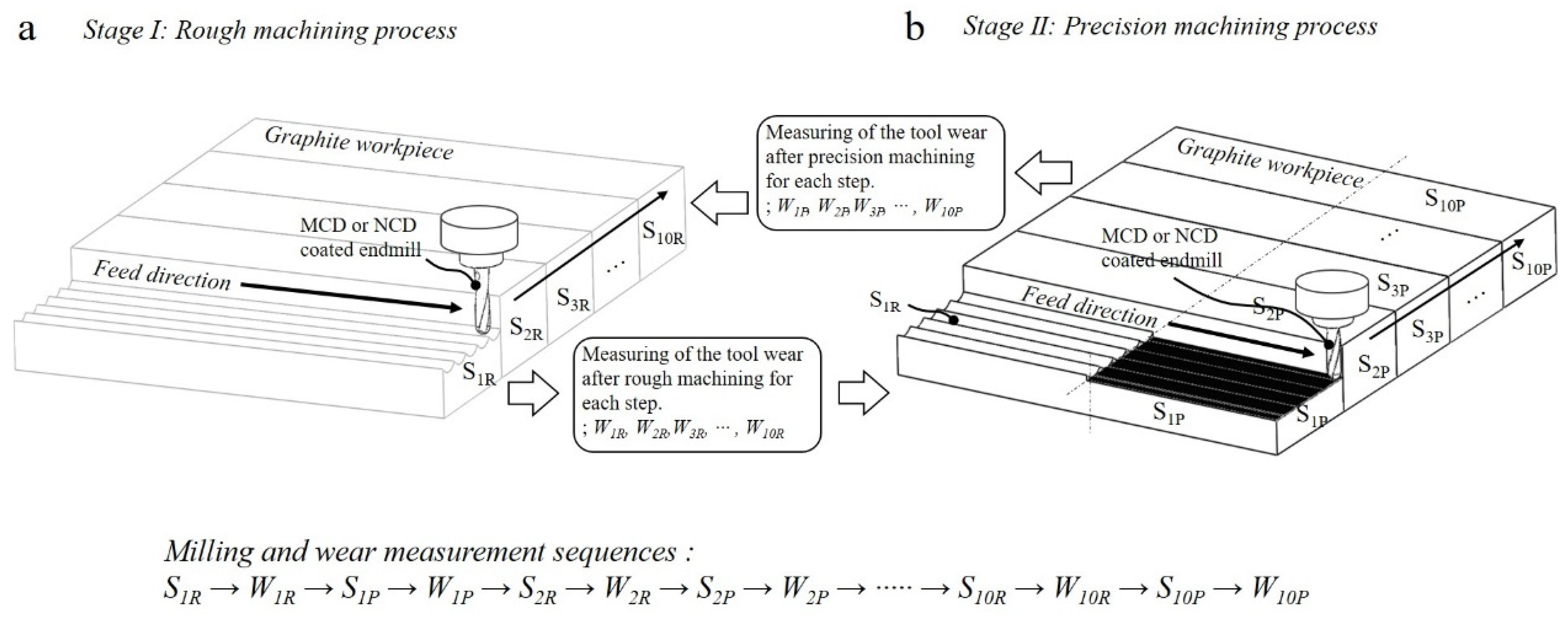
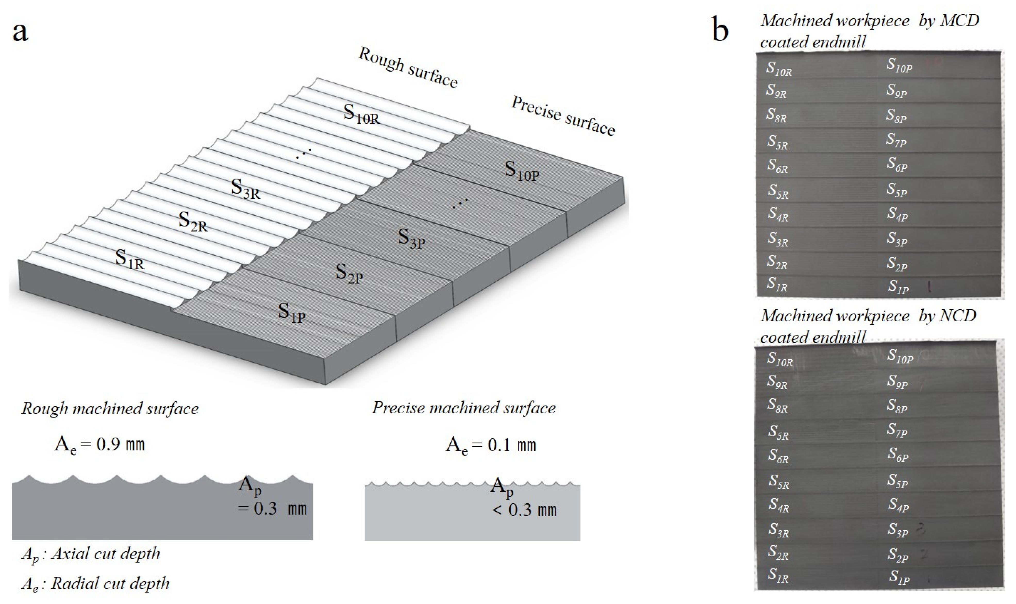
2.3. Experimental Conditions and Procedures
3. Results and Discussion
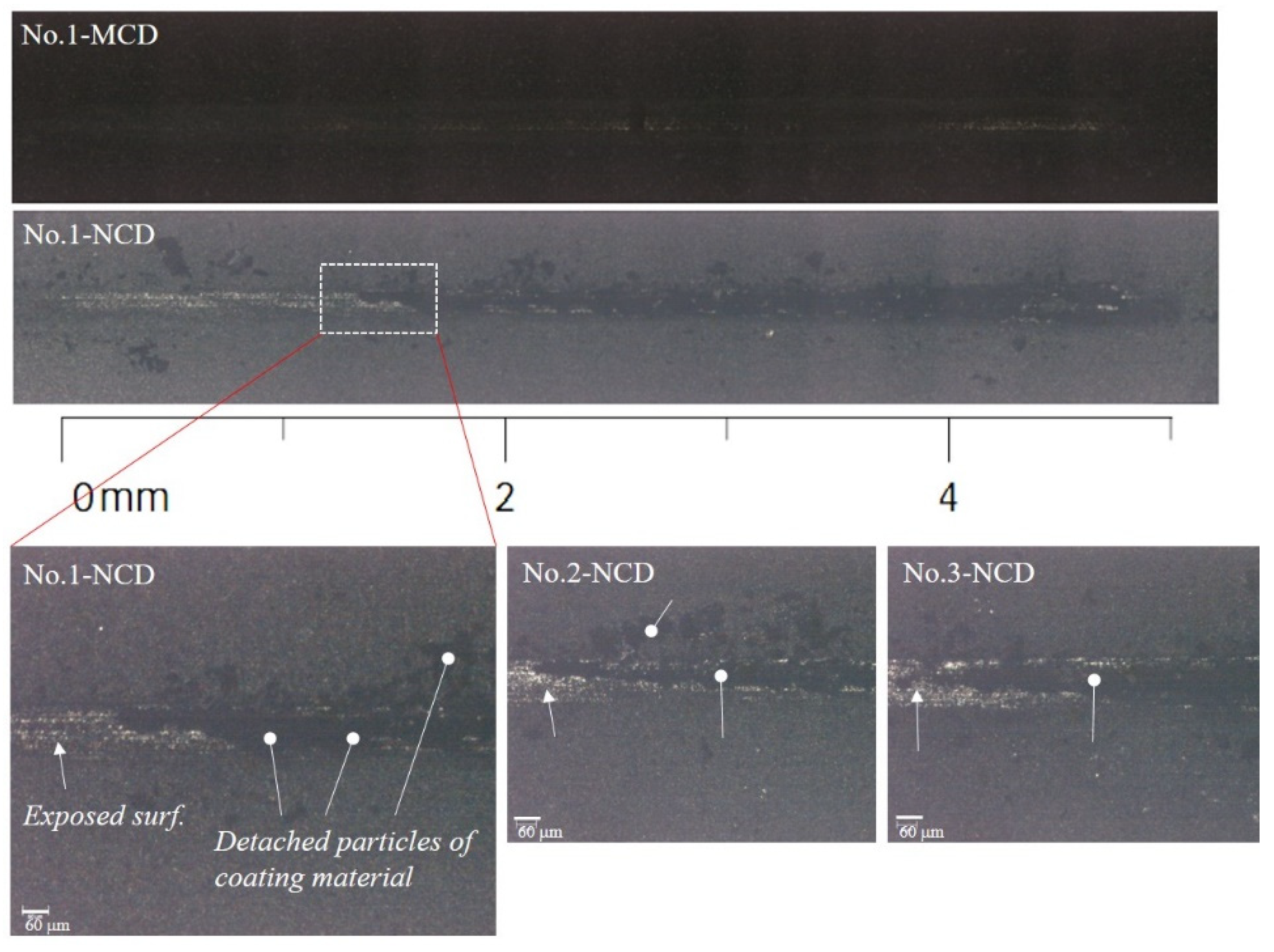
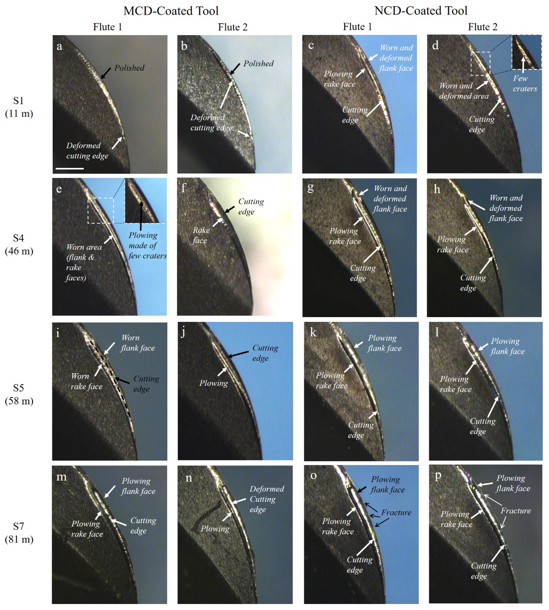
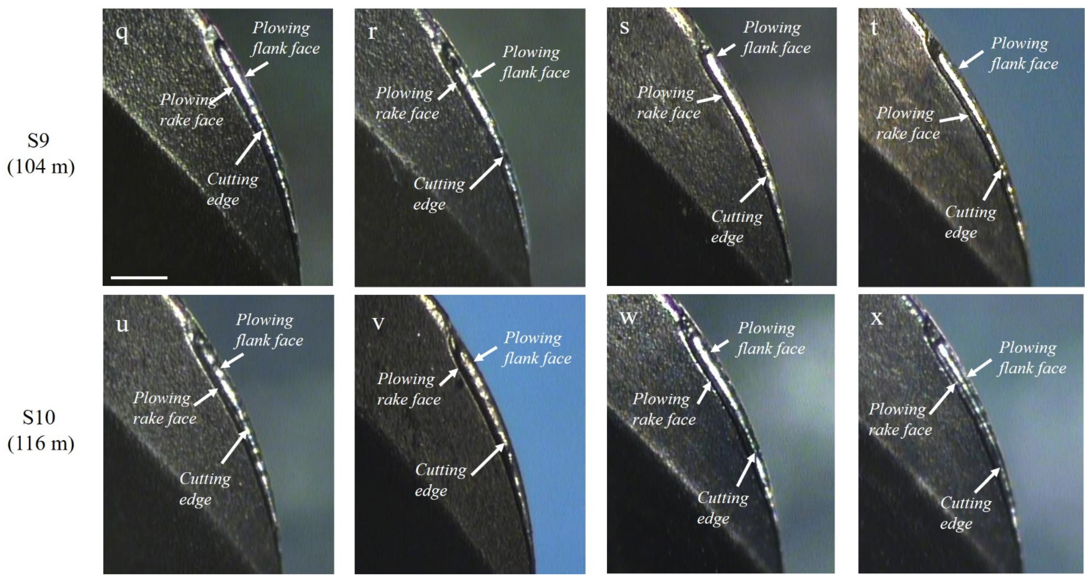
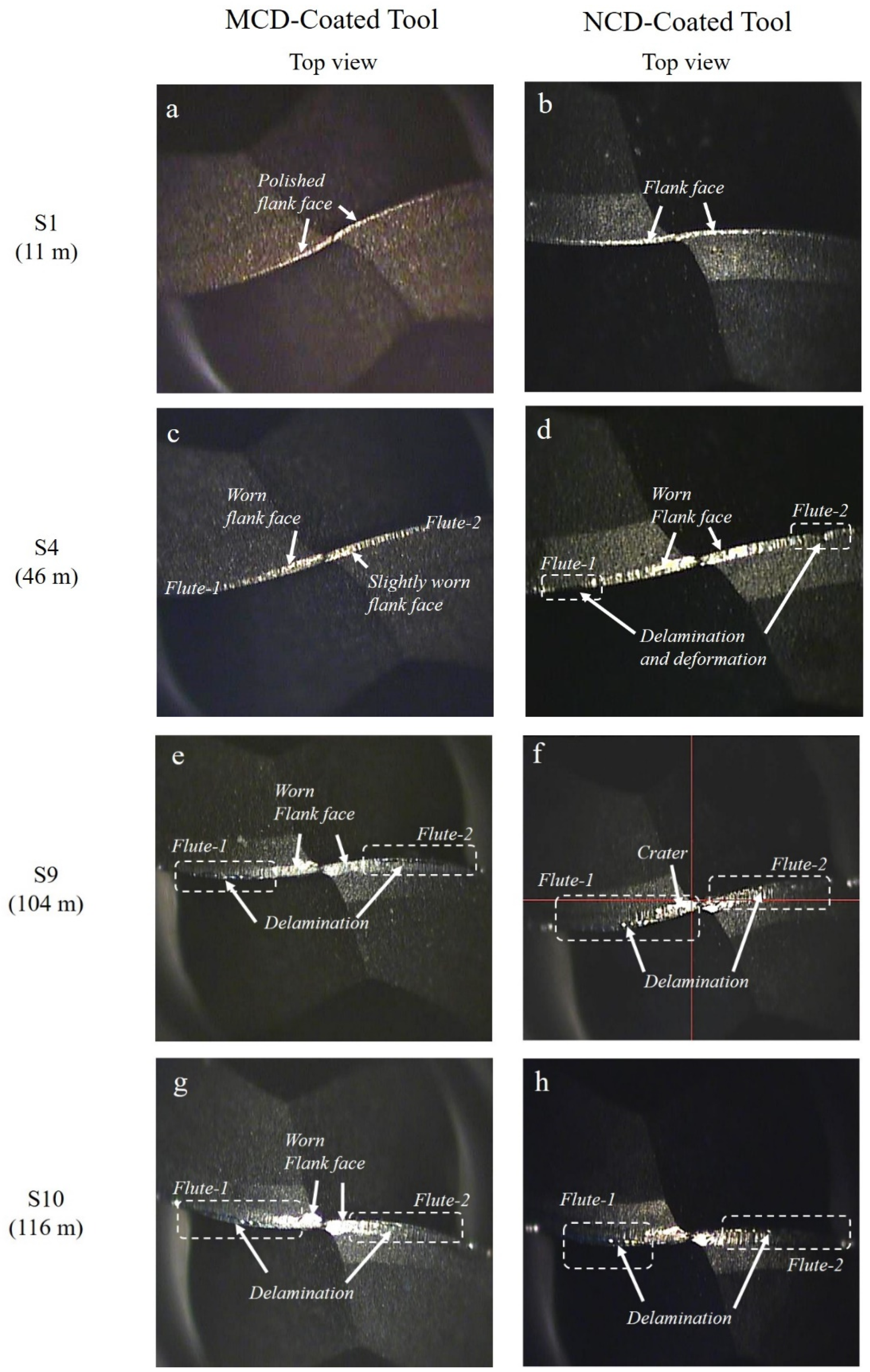
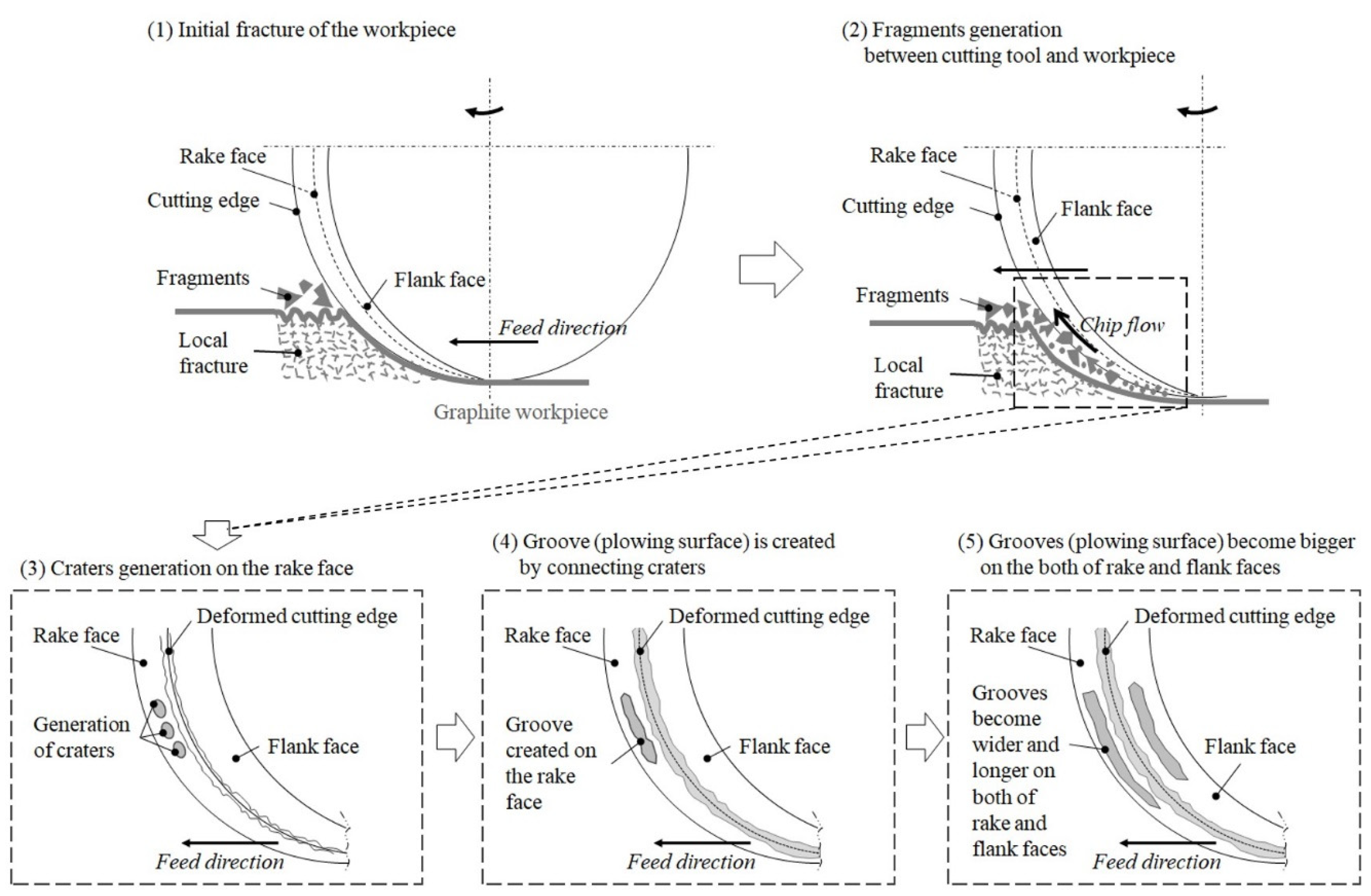
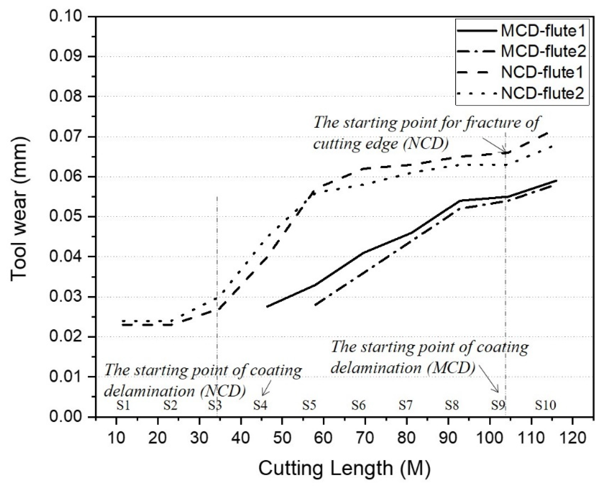
3.1. Tool Wear of Diamond-Coated Endmills
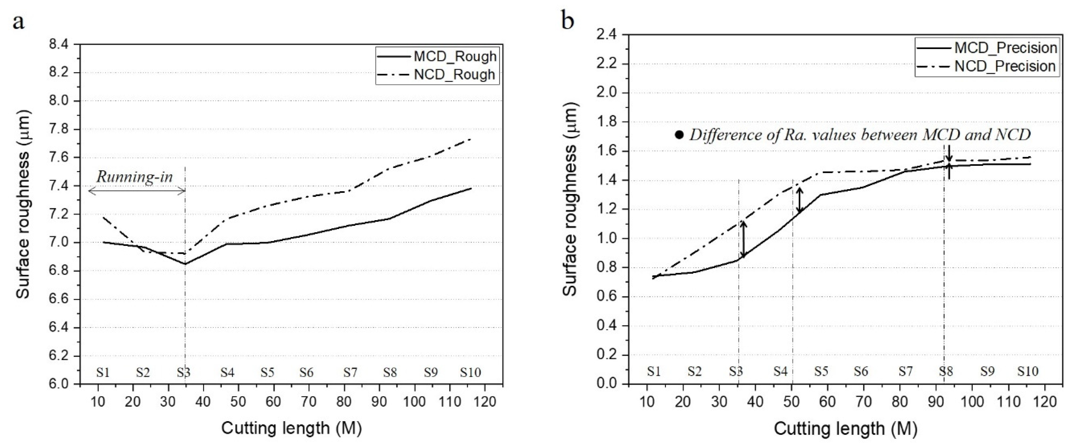
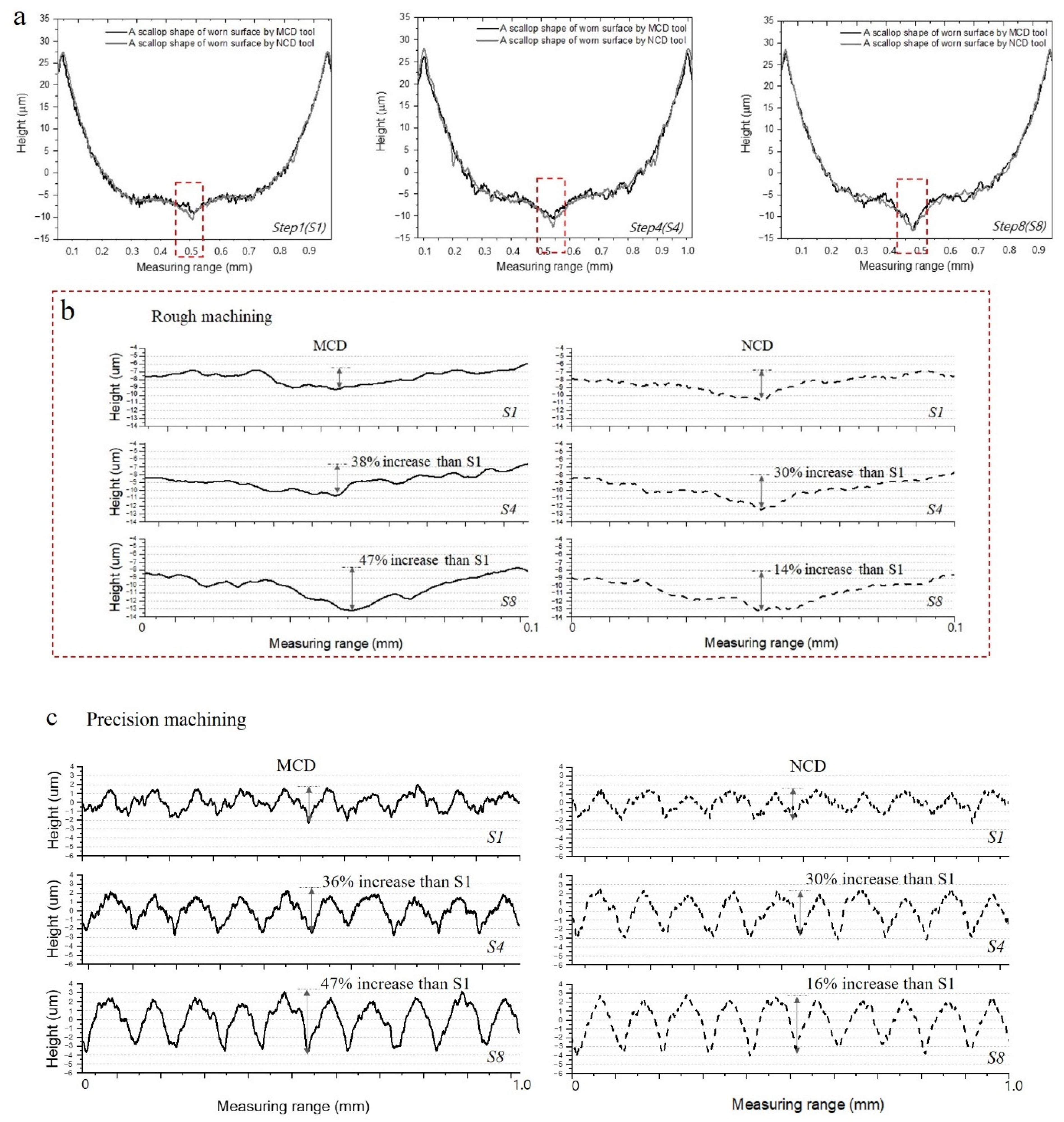
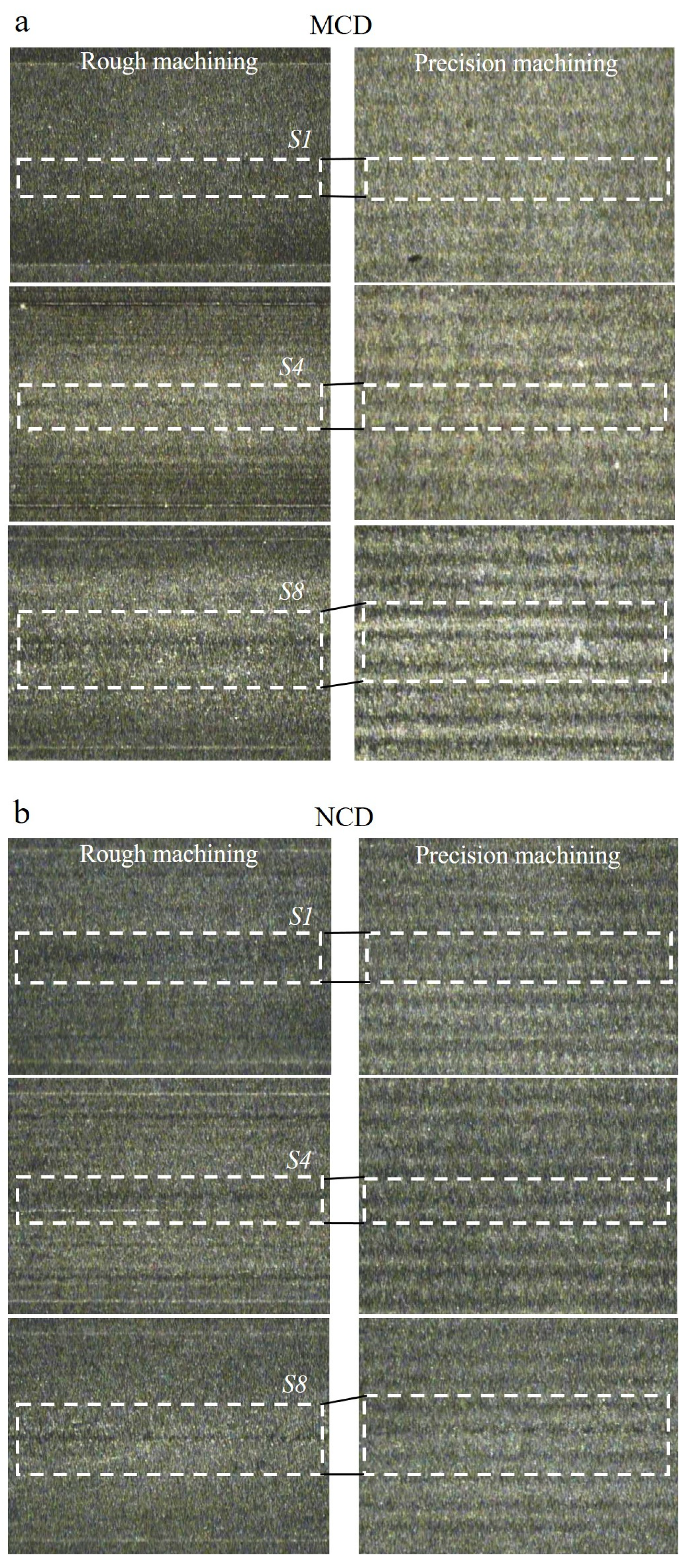
3.2. Relations between Machined Surface, Surface Roughness, and Tool Wear
4. Conclusions
- The wear of the tool flank and rake faces progressed the same during machining regardless of the type of crystalline diamond coating. However, the total tool wear differed as the delamination and damage times changed according to the adhesion strength of the coating layer.
- The size of the diamond crystal was not a dominant factor on coating wear, but it had a major impact on the wear of the machined surface in contact with the cutting edge centre during precision machining. Therefore, despite an increasing cutting length, the NCD-coated tool with a fine grain size showed a decrease in the abrasive wear rate of the machined surface.
- For rough machining, delamination wear was the wear mechanism for the MCD and NCD coatings. Therefore, the MCD coating, which had a higher bonding force with the substrate, showed a higher performance in terms of service life and machinability.
- When rough and precision machining processes were performed with one tool, the two coated tools provided similar roughness on the final machined surface.
Author Contributions
Funding
Institutional Review Board Statement
Informed Consent Statement
Data Availability Statement
Conflicts of Interest
References
- Ashby, M.F. Materials Selection in Mechanical Design, 3rd ed.; Elsevier Butterworth–Heinemann: Oxford, UK, 2005. [Google Scholar] [CrossRef]
- Yang, Y.K.; Chuang, M.T.; Lin, S.S. Optimization of dry machining parameters for high-purity graphite in endmilling process via design of experiments methods. J. Mater. Process. Technol. 2009, 209, 4395–4400. [Google Scholar] [CrossRef]
- Wang, C.Y.; Zhou, L.; Fu, H.; Hu, Z.L. High speed milling of graphite electrode with endmill of small diameter. Chin. J. Mech. Eng. 2007, 20, 27–31. [Google Scholar] [CrossRef]
- Cabral, G.; Reis, P.; Polini, R.; Titus, E.; Ali, N.; Davim, J.P.; Grácio, J. Cutting performance of time-modulated chemical vapour deposited diamond coated tool inserts during machining graphite. Diam. Relat. Mater. 2006, 15, 1753–1758. [Google Scholar] [CrossRef]
- Wang, H.; Yang, J.; Sun, F. Cutting performances of MCD, SMCD, NCD and MCD/NCD coated tools in high-speed milling of hot bending graphite molds. J. Mater. Process. Technol. 2020, 276, 116401. [Google Scholar] [CrossRef]
- Singla, A.; Singh, N.K.; Singh, Y.; Jangir, D.K. Micro and nano-crystalline diamond coatings of co-cemented tungsten carbide tools with their characterization. J. Bio-Tribo-Corros. 2021, 7, 35. [Google Scholar] [CrossRef]
- Bian, R.; Ferraris, E.; Ynag, Y.; Qian, J. Experimental investigation on ductile mode micro-milling of ZrO2 ceramics with diamond-coated end mills. Micromachines 2018, 9, 127. [Google Scholar] [CrossRef] [PubMed] [Green Version]
- Wang, L.; Lei, X.L.; Shen, B.; Sun, F.H.; Zhang, Z.M.; Chen, M. Cutting performances of boron doped diamond-coated milling tools in machining graphite. Mater. Sci. Forum 2012, 697, 458–461. [Google Scholar] [CrossRef]
- Suwa, H.; Sakamoto, S.; Nagata, M.; Tezuka, K.; Samukawa, T. Applicability of diamond-coated tools for ball end milling of sintered tungsten carbide. Int. J. Autom. Technol. 2020, 14, 18–25. [Google Scholar] [CrossRef]
- Lei, X.L.; Wang, L.; Shen, B.; Sun, F.H.; Zhang, Z.M.; Chen, M. Fabrication and application of diamond coated micro ball end mills. Mater. Sci. Forum 2012, 697, 462–465. [Google Scholar] [CrossRef]
- Okada, M.; Yoshida, A.; Furumoto, T.; Watanabe, H.; Asakawa, N.; Otsu, M. Mechanisms and characteristics of direct cutting of tungsten carbide using a diamond-coated carbide endmill. Int. J. Adv. Manuf. Technol. 2016, 86, 1827–1839. [Google Scholar] [CrossRef]
- Aleksandrov, F.T.; Kurtela, M.; Sakoman, M.; Šnajdar, M.M. Influence of Co Content and Chemical Nature of the Co Binder on the Corrosion Resistance of Nanostructured WC-Co Hardmetals in Acidic Solution. Materials 2021, 14, 3933. [Google Scholar] [CrossRef]
- Najar, K.A.; Islam, S.A.; Sheikh, N.A. Surface engineering of tungsten carbide tool material by nano and microcrystalline diamond coatings. In Surface Engineering of Modern Materials; Springer: Cham, Switzerland, 2020; pp. 149–163. [Google Scholar] [CrossRef]
- Sun, F.H.; Zhang, Z.M.; Shen, H.S.; Chen, M. Growth of nanocrystalline diamond films on co-cemented tungsten carbide substrates by hot filament CVD. Mater. Sci. Forum 2004, 471, 52–58. [Google Scholar] [CrossRef]
- Dumpala, R.; Chandran, M.; Kumar, N.; Dash, S.; Ramamoorthy, B.; Rao, M.R. Growth and characterization of integrated nano- and microcrystalline dual layer composite diamond coatings on WC–Co substrates. Int. J. Refract. Met. Hard Mater. 2013, 37, 127–133. [Google Scholar] [CrossRef]
- Wang, L.; Liu, Y.; Chen, H.; Wang, M. Modification methods of diamond like carbon coating and the performance in machining applications: A review. Coatings 2022, 12, 224. [Google Scholar] [CrossRef]
- Wang, C.; Wang, X.; Sun, F. Tribological behavior and cutting performance of monolayer, bilayer and multilayer diamond coated milling tools in machining of zirconia ceramics. Surf. Coat. Technol. 2018, 353, 49–57. [Google Scholar] [CrossRef]
- Kanda, K.; Takehana, S.; Yoshida, S.; Watanabe, R.; Takano, S.; Ando, H.; Shimakura, F. Application of diamond-coated cutting tools. Surf. Coat. Technol. 1995, 73, 115–120. [Google Scholar] [CrossRef]
- Suh, N.P. The delamination theory of wear. Wear 1973, 25, 111–124. [Google Scholar] [CrossRef]
- Williams, J. Wear and surface damage. In Engineering Tribology; Cambridge University Press: Cambridge, MA, USA, 2005; pp. 166–199. [Google Scholar] [CrossRef]
- Lee, H.H.; Lee, S.; Park, J.K.; Yang, M. Friction and wear characteristics of surface-modified titanium alloy for metal-on-metal hip joint bearing. Int. J. Precis. Eng. Manuf. 2018, 19, 917–924. [Google Scholar] [CrossRef]
- Qu, J.; Blau, P.J.; Watkins, T.R.; Cavin, O.B.; Kulkarni, N.S. Friction and wear of titanium alloys sliding against metal, polymer, and ceramic counterfaces. Wear 2005, 258, 1348–1356. [Google Scholar] [CrossRef]
- Yu, K.H.; Cheong, C.Y. A study on the precision cutting characteristics by the diamond tool on the cutting distance. J. Korean Soc. Mach. Tool Eng. 1998, 7, 127–133. [Google Scholar]
- Ernest, R. Friction and Wear of Materials, 2nd ed.; John Wiley & Sons: New York, NY, USA, 1995; pp. 191–206. [Google Scholar]


| Mechanical Property | Value |
|---|---|
| Bulk density (g/cm3) | 1.84 |
| Grain size (μm) | 7 |
| Flexural strength (MPa) | 72 |
| Hardness Rockwell “H” | 90 |
| Geometry | Parameter | Value |
|---|---|---|
 | Radius R (mm) | 1.5 |
| Diameter of tool shank d (mm) | 6.0 | |
| Cut length l1 (mm) | 8.0 | |
| Effective length l2 (mm) | 16.0 | |
| Tool length L (mm) | 60.0 | |
| Helix angle θ (°) | 30 | |
| Flute number z | 2 |
| Grain Size (um) | Cobalt (%) | Density (g/cm3) | Hardness (HV30) |
|---|---|---|---|
| 1.0 | 6.0 | 14.9 ± 0.1 | 1740 ± 50 |
| Scratch Parameter | Value |
|---|---|
| Load range (N) | 1–30 |
| Load rate (N/min) | 58 |
| Acoustic emission sensitivity | 9 |
| Scanning load (N) | 0.1 |
| Speed (mm/min) | 10 |
| Length (mm) | 5 |
| Milling Parameter | Value |
|---|---|
| Cutting velocity Vc (m/min) | 104 |
| Spindle speed N (rpm) | 11,000 |
| Feed rate F (mm/min) | 1200 |
| Feed per tooth fz (mm/tooth) | 0.055 |
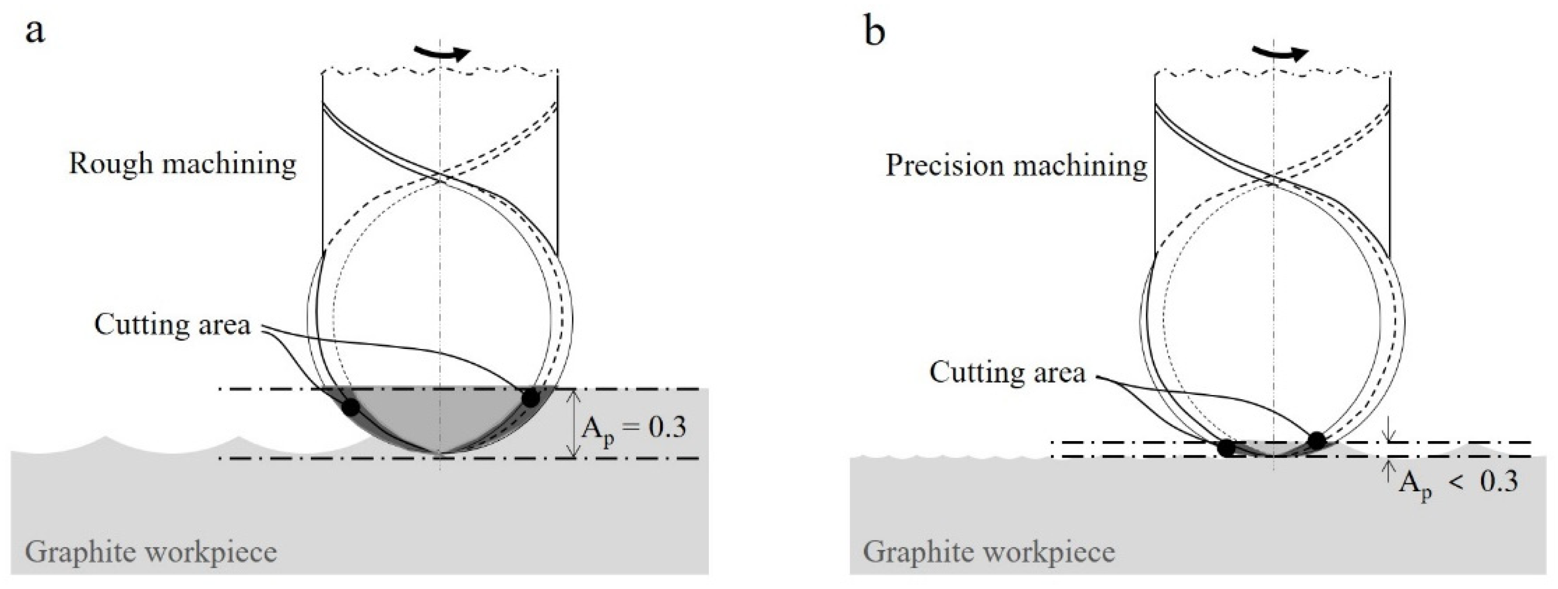
| Axial cut depth Ap (mm) | 0.3 (rough machining)/<0.3 (precision machining) |
| Radial cut depth Ae (mm) | 0.9 (rough machining)/0.1 (precision machining) |
| Total cutting length (m) | 104.4 (rough machining)/12 (precision machining) |
| Lubrication environment | Dry |
Publisher’s Note: MDPI stays neutral with regard to jurisdictional claims in published maps and institutional affiliations. |
© 2022 by the authors. Licensee MDPI, Basel, Switzerland. This article is an open access article distributed under the terms and conditions of the Creative Commons Attribution (CC BY) license (https://creativecommons.org/licenses/by/4.0/).
Share and Cite
Lee, H.; Kim, J.; Park, J.; Kim, J. Analysis of Tool Wear and Roughness of Graphite Surfaces Machined Using MCD and NCD-Coated Ball Endmills. Micromachines 2022, 13, 766. https://doi.org/10.3390/mi13050766
Lee H, Kim J, Park J, Kim J. Analysis of Tool Wear and Roughness of Graphite Surfaces Machined Using MCD and NCD-Coated Ball Endmills. Micromachines. 2022; 13(5):766. https://doi.org/10.3390/mi13050766
Chicago/Turabian StyleLee, Hyeonhwa, Jinsoo Kim, Jeongyeon Park, and Jongsu Kim. 2022. "Analysis of Tool Wear and Roughness of Graphite Surfaces Machined Using MCD and NCD-Coated Ball Endmills" Micromachines 13, no. 5: 766. https://doi.org/10.3390/mi13050766