Article

Vision-Based Moving-Target Geolocation Using Dual Unmanned Aerial Vehicles

1
Department of Computer Science and Technology, Harbin Engineering University, Harbin 150009, China
2
Defense Innovation Institute, Chinese Academy of Military Science, Beijing 100071, China
*
Author to whom correspondence should be addressed.
These authors contributed equally to this work.
Remote Sens. 2023, 15(2), 389; https://doi.org/10.3390/rs15020389
Submission received: 1 November 2022 / Revised: 4 January 2023 / Accepted: 5 January 2023 / Published: 8 January 2023

Abstract

:
This paper develops a framework for geolocating ground-based moving targets with images taken from dual unmanned aerial vehicles (UAVs). Unlike the usual moving-target geolocation methods that rely heavily on accurate navigation state sensors or assumptions of the known target’s altitude, the proposed framework does not have the same limitations and performs geolocation of moving targets utilizing dual UAVs equipped with the low-quality navigation state sensors. Considering the Gaussian measurement errors and yaw-angle measurement bias provided by low-quality sensors, we first propose an epipolar constraint-based corresponding-point-matching method, which enables the historical measurement data to be used to estimate the current position of the moving target; after that, we propose a target altitude estimation method based on multiview geometry, which utilizes multiple images, including historical images, to estimate the altitude of the moving target; finally, considering the negative influence of yaw-angle measurement bias on the processes of target altitude estimation and parameter regression, we take advantage of multiple iterations among the two processes to accurately estimate the moving target’s two-dimensional position and the yaw-angle measurement biases of two UAVs. The effectiveness and practicability of the framework proposed in this paper are proved by simulation experiments and actual flight experiments.

1. Introduction

In recent years, with the advantages of small size, simple operation, and low price [1,2,3], unmanned aerial vehicles (UAVs) are increasingly being deployed for a wide variety of missions, including surveillance and reconnaissance. UAV-based computer vision capabilities, such as target detection and tracking, play particularly important roles in the above missions. However, it is not sufficient to simply detect and track a moving target; we often need to know the three-dimensional position of the moving target, which is obtained by the process of target geolocation [4,5,6]. In this paper, target geolocation refers to the process of using UAVs to obtain target information and estimate the position of the target in the world coordinate system. In this process, GPS (global positioning system) and AHRS (attitude and heading reference system) are used to acquire the UAV’s navigation state, such as position and attitude, for geolocation in real time; the UAV’s navigation state and the target’s image are acquired simultaneously. There have been many studies on ground target geolocation technology [7,8,9]. Fabian et al. [10] analyzed the factors that affect the accuracy of moving-target geolocation. Generally speaking, a precise geolocation result depends on accurate navigation state measurement of UAVs and target’s altitude. Therefore, it is difficult to obtain the accurate geolocation result of the non-cooperative target utilizing the onboard low-quality navigation state sensors. For this reason, this paper aims to achieve accurate geolocation by using only vision to mitigate the effects of Gaussian measurement errors and the yaw-angle measurement bias, and to accurately estimate the position of the grounded moving target, which is a challenge.
In recent years, scholars have conducted a considerable amount of research on moving-target geolocation using UAV systems. In general, moving-target geolocation methods can be divided into two categories: the methods based on one-shot learning [11,12,13,14] and the methods based on multiview geometry [15,16,17]. As the most commonly used method, the one-shot method only obtains one image of the moving target but require the altitude of the moving target. There are many ways to get the altitude information of the moving target. Some researchers utilized a DEM (digital elevation model) to obtain the altitude of the moving target. Qiao et al. [18] proposed a vision-based geolocation frame could estimate the three-dimensional position of a moving target in real time with a gimbal-stabilized camera, but an accurate digital elevation model is required to obtain the altitude of a moving target on the ground. Alternatively, some researchers obtained the target’s altitude through estimating the distance between the UAV and the moving target based on the size of the target in the image. Zhang et al. [19] proposed a relative distance estimation method based on the prior information of the target that required the size of the target to be known and then used the geometric relationship to calculate the distance between the UAV and the target. Zhu et al. [20] showed that their learning-based method could estimate the distance to a specific target. Nevertheless, their experimental results showed that the distance estimation methods based on prior information work well only if the target is close and are not suitable for accurately geolocating grounded targets with UAVs. In practical applications, the distance from the UAV to the target is usually determined by a laser rangefinder [11], which has the highest accuracy among the above-mentioned methods. However, the use of laser-based methods for the continuous geolocation of moving targets will greatly reduce the flight time of UAVs due to the weight of the laser rangefinder. It is worth noting that the above-mentioned methods all assume that the UAV’s navigation state is accurate; that is, they do not consider the negative influence of the measurement errors of the UAV’s navigation state on the ground moving-target geolocation.
To avoid the limits of the above-mentioned methods, some researchers utilized multiple UAVs to simultaneously acquire multiple images of a moving target and estimated its position by multiview geometry. Wang et al. [21] utilized multiple UAVs to geolocate a moving target and presented nonlinear filter based on solving the Fokker–Planck equation to address the issue of the time delay during data transmission. Xu et al. [22] proposed a method to adaptively adjust the weights according to the positions of the UAVs, which can improve the accuracy of the results of the weighted least-squares. However, these methods did not solve the problems well. On the one hand, mitigating the negative influence of Gaussian measurement errors on geolocation requires multiple images, and each UAV can only obtain one image at a time, which means that a large number of UAVs are required for accurate moving-target geolocation. On the other hand, although the above-mentioned methods using multiple measurements can mitigate the influence of Gaussian measurement errors provided by the navigation state sensors, they still have not solved the problem of yaw-angle measurement bias.
The yaw-angle bias provided by the AHRS may vary every time when the AHRS is initialized, and the assumption of unknown and constant bias is justified in a short time window [23]. Related to this, Zhang et al. [24] proposed a vision-based target geolocation method, which focuses on eliminating the effects of yaw-angle measurement bias provided by low-quality sensors on target geolocation. Further, Zhang et al. [25] focused on improving the estimation accuracy of yaw-angle bias by utilizing a particle swarm optimization algorithm to derive an expression of the optimal trajectory and perform optimal trajectory planning and then to enhance the geolocation performance. However, their methods can only be applied to the stationary-target geolocation scenarios.
In the scenario assumed in this paper, two UAVs follow a single moving target on the ground and estimate the position of the moving target in real time. Except for the images of the moving target, all the information of the target is unknown. Both UAVs are equipped with monocular cameras to obtain target images. In addition, UAVs are equipped with GPS and AHRS to obtain their own positional and attitude information. In the navigation state measurement of UAVs, there are Gaussian measurement errors for position and attitude information, and due to different measurement principles, there are also measurement biases for yaw angle. The purpose of this paper is to mitigate the negative impact of UAV navigation state measurement errors on moving-target geolocation accuracy in the above scenario. In order to deal with this issue, we develop a ground-based moving-target geolocation framework utilizing dual UAVs, and the constructed system is shown in Figure 1. The proposed framework is free from the above-mentioned constraint of assuming the ground target is stationary, and it geolocates the moving target using sequential images taken from dual UAVs and navigation states provided by low-quality sensors.
The main contributions of this paper are as follows.
  • We propose a ground moving-target geolocation framework that utilizes only the sequence of images obtained by two UAVs with low-quality sensors. The framework contains the processes of corresponding point matching, target altitude estimation, and parameter regression, which are used to mitigate the negative influences of Gaussian measurement errors and yaw-angle biases.
  • In order to obtained more available images using only two UAVs, we propose a corresponding-point-matching method based on epipolar constraint. The method enables the historical images to be used to estimate the current position of the moving target. In addition, in order to filter out the wrong corresponding points, we propose an outer point filtering method based on the consistency principle.
  • The effectiveness of the proposed framework was verified via the experiments in simulated and real environments.

2. Methods

The proposed ground moving-target geolocation framework based on dual UAVs is illustrated in Figure 2. The framework utilizes a multiprocess architecture to process the four tasks of data acquisition, target detection, corresponding point matching, and moving-target geolocation in parallel. Moreover, in the moving-target geolocation, the two subtasks of target altitude estimation and parameter regression are processed iteratively.
The data acquisition process uses two UAVs equipped with a camera and low-quality navigation sensors to track the moving target and obtain the images of the target and the navigation states of two UAVs simultaneously; then, the images and navigation states are transmitted to the ground station in real time. The target detection process obtains the latest image from each UAV and achieves accurate detection of the moving target with the image pair. The corresponding point matching is to provide sufficient measurement data for the subsequent moving-target geolocation; it matches the corresponding points in the past images according to the target points provided by the target detection process, and then the past frames’ images can be utilized to estimate the current position of the moving target. The process of target altitude estimation aims to estimate the target’s altitude utilizing the current images and the past images. After that, the target’s altitude is used by the parameter regression process to estimate the two-dimensional position of the target and the yaw-angle measurement biases of two UAVs. Considering the yaw-angle measurement biases, there are several iterations between the target altitude estimation and the parameter regression until the estimated yaw-angle biases are less than the given threshold or the number of iterations reaches the given maximum.

2.1. Parameter Regression

The parameter regression is used to estimate the two-dimensional position of target and the yaw-angle measurement biases of two UAVs. The target geolocation model based on UAV can be visualized in Figure 3.
According to [24], it can be expressed as
x P y P = x v y v + z P z v 0 , 0 , 1 C w c x p y p f × 1 0 0 0 1 0 C w c x p y p f
where ( x P , y P , z P ) T and ( x v , y v , z v ) T represent the coordinates of the current target’s position P and the UAV’s position in the world coordinate system w, respectively. The coordinates of projection point p of current target’s position P are represented as ( x p , y p ) in the image plane; and f is the focal length of the camera. In a simulation experiment, the precise focal lengths can be obtained directly. In a real experiment, we used the kit provided by ROS [26] to calibrate the cameras to obtain the focal lengths. The UAV’s navigation state ( x v , y v , z v , ψ , θ , ϕ ) was measured by the onboard GPS and AHRS. The rotation matrix C c w represents the transformation from the camera coordinate system c to the world coordinate system w. The relative altitude h between the current target’s position and the UAV is defined as
h = z v z P
In general, the pitch angle θ and the roll angle ϕ of a UAV can be measured accurately, but the yaw-angle measurement will have large error due to the use of magnetometer. Hence, to solve the above-mentioned issue, we estimate the yaw-angle measurement biases of two UAVs and target’s position by parameter regression. The estimation process is illustrated as follows.
The goal of parameter regression is to estimate the parameter ξ = [ ξ 1 , ξ 2 ] T , where
ξ 1 : = [ x P , y P ] T
is the two-dimensional coordinate of the moving target and
ξ 2 : = [ δ ψ L , δ ψ R ] T
are the yaw-angle measurement biases of the left UAV and right UAV, respectively. The measured navigation state of two UAVs is τ = [ τ 1 , τ 2 , τ 3 ] T , where
τ 1 : = [ x v L , y v L , z v L , x p L , y p L , θ L , ϕ L ] T
is the navigation state of the left UAV and
τ 2 : = [ x v R , y v R , z v R , x p R , y p R , θ R , ϕ R ] T
is the navigation state of the right UAV. The measured navigation state τ 3 : = [ ψ L , ψ R ] T includes the yaw angles of the left UAV and the right UAV, respectively. According to (1), the general form of the measurement equation is as follows:
ξ 1 = F ( τ 1 , τ 2 , τ 3 )
and the actual measurements are
γ 1 = τ 1 + w 1 , w 1 N ( 0 , Q 1 )
γ 2 = τ 2 + w 2 , w 2 N ( 0 , Q 2 )
γ 3 = τ 3 + ξ 2 + w 3 , w 3 N ( 0 , Q 3 )
where the Gaussian measurement noise covariances Q 1 and Q 2 are both 7 × 7 symmetric positive-definite matrices, and Q 3 is a 2 × 2 symmetric positive-definite matrix. Combine (8), (9) and (10) into the measurement equation as follows:
ξ 1 = F ( γ 1 w 1 , γ 2 w 2 , γ 3 ( ξ 2 + w 3 ) )
Then, the linearized measurement equation is obtained by using Taylor’s theorem:
F ( γ 1 , γ 2 , γ 3 ) ξ 1 + F τ 1 γ 1 , γ 2 , γ 3 · w 1 + F τ 2 γ 1 , γ 2 , γ 3 · w 2 + F τ 3 γ 1 , γ 2 , γ 3 · w 3 + F τ 3 γ 1 , γ 2 , γ 3 · ξ 2
Suppose that 2 N bearing measurements of the moving target are taken by the left UAV and the right UAV at the discrete time t = 1 , , N ; that is, ( γ 1 1 , γ 2 1 , γ 3 1 ) ,…, ( γ 1 N , γ 2 N , γ 3 N ) . For 2 N bearing measurements, the linear measurement equations are as follows:
F ( γ 1 1 , γ 2 1 , γ 3 1 ) · · F ( γ 1 N , γ 2 N , γ 3 N ) = I 2 F τ 3 γ 1 1 , γ 2 1 , γ 3 1 · · · · I 2 F τ 3 γ 1 N , γ 2 N , γ 3 N ξ + W
where
W N ( 0 , Q )
is the geolocation error caused by the Gaussian measurement error of the UAV’s navigation state, and its convariance matrix is as follows:
Q = d i a g F τ 1 γ 1 k , γ 2 k , γ 3 k Q 1 F τ 1 γ 1 k , γ 2 k , γ 3 k T + F τ 2 γ 1 k , γ 2 k , γ 3 k Q 2 F τ 2 γ 1 k , γ 2 k , γ 3 k T + F τ 3 γ 1 k , γ 2 k , γ 3 k Q 3 F τ 3 γ 1 k , γ 2 k , γ 3 k T k = 1 N
From (13), the two-dimensional position of moving target and the yaw-angle biases of two UAVs can be solved effectively with the weighted least-square method.

2.2. Estimation of Target Altitude

It can be seen in (1) that the target’s altitude z P is required by the process of parameter regression. In this section, the target’s altitude z P is obtained by utilizing the multiview geometry.
The left UAV and the right UAV continuously acquire the navigation state and the target images when tracking the moving target. We select the current image and N 1 past images from the sequence of images taken by each UAV as the measurement data to estimate the current position of the moving target, and the two adjacent images in these N images must meet the baseline constraint—that is, the distance between the positions of UAV when taking these two images must be greater than or equal to the given threshold. Any image g L i ( i = 1 , . . . , N ) taken by the left UAV and any image g R j ( j = 1 , . . . , N ) taken by the right UAV can be form an image pair m i j , and a total of N 2 image pairs can be obtained. For each image pair m i j , its multiview geometry model is shown in Figure 4. The points p L and p R are the corresponding points of the target’s position P projected in the left image, g L i , and the right image, g R j , respectively. The corresponding points in the current images are provided by target detection process, but the corresponding points in the past images are provided by the process of corresponding point matching described in Section 2.3. O L and O R are the origins of the left and right camera coordinate systems, respectively. According to the principle of multiview geometry, if there is no measurement error, the lines O L p L and O R p R will intersect at point P. Nevertheless, due to the Gaussian measurement error and yaw-angle biases provided by the low-quality sensors, the lines will not intersect at the point P. Therefore, we approximate the intersection point P to the nearest point P from the two lines.
Let a p L ( a R ) , T R L + b R R L T p R ( b R ) be ray O L p L and ray O R p R in the left coordinate system, respectively. We denote J as an orthogonal vector with the rays O L p L and O R p R . The problem is now simplified to searching the midpoint P of the line segment parallel to J that joins O L p L and O R p R .
The endpoints of the line segment ( a 0 p L and T R L + b 0 R R L T p R ) are calculated to solve the following equation:
p L R R L T p R p L × R R L T p R a b c = T R L
for a 0 , b 0 , and c 0 . We let h i j be the relative altitude between the target and the UAV when taking the image g L i , and h i j is estimated utilized image g L i and g R j . Similarly, h j i is the relative altitude between the target and the UAV when taking the image g R j , and h j i is estimated utilizing image g R j and g L i . Thus, the relative altitude h i j and h j i can be obtained from the following equations:
h i j = 1 2 0 0 1 R L a 0 p L + b 0 R R L p R + T R L
h j i = 1 2 0 0 1 R R b 0 p R + a 0 R L R p L + T L R
where p L : = [ x p L , y p L , f L ] T and p R : = [ x p R , y p R , f R ] T are the coordinates of the corresponding points in the left and right coordinate systems, respectively. The matrices R R L and T R L are the rotation matrix and displacement matrix from the right coordinate system to the left coordinate system, respectively. Similarly, the matrices R L R and T L R are the rotation matrix and displacement matrix from the left coordinate system to the right coordinate system respectively. That is,
R L : = C c n ( ψ i + δ ψ L n , θ i , ϕ i ) , R R : = C c n ( ψ j + δ ψ R n , θ j , ϕ j )
where δ ψ L n and δ ψ R n is the estimated value given by parameter regression in the n t h iteration and the initial values δ ψ L 0 = δ ψ R 0 = 0 . There are N image pairs containing image g L i or image g R j , so we can get N estimates of relative altitude for each image g L i or image g R j . Thus, we can get the average altitude h ¯ i and h ¯ j for image g L i and g R j by the following equations, respectively.
h ¯ i = j = 1 N h i j N , h ¯ j = i = 1 N h j i N
After that, we estimate the target’s altitude according to the indirect adjustment theory. After the estimation of relative altitude, each image g k ( k = 1 , . . . , 2 N ) has an estimated relative altitude h ¯ k . There is estimation error for relative altitude h ¯ k and measurement error for UAV’s altitude z v k . According to (2), we have
z v k + e v k = z P + h ¯ k + e h k
where e v k is the measurement error of z v k and e h k is the estimation error of h ¯ k . For 2 N images, we use E k to represent e v k e h k and have
E 1 · · E 2 N = J 2 N , 1 z P z v 1 h ¯ 1 · · z v 2 N h ¯ 2 N
where J 2 N , 1 represents the 2 N × 1 matrix of ones. According to the least-squares theory, z P can be obtained as follows:
z P = ( J 2 N , 1 T J 2 N , 1 ) 1 J 2 N , 1 T z v 1 h ¯ 1 · · z v 2 N h ¯ 2 N
Finally, the estimated altitude of the moving target is used to estimate the yaw-angle biases and the two-dimensional positions described in Section 2.1.

2.3. Corresponding Point Matching

In this paper, the corresponding points refer to the projection points of the target’s current position P on different images. The target points provided by target detection in the current images g L 1 and g R 1 captured by the left and right UAVs, respectively, are corresponding points of the moving target’s current position, but the target points provided by target detection in the past images cannot be regarded as corresponding points because the target’s position has changed. Therefore, it is necessary to match the corresponding points before using the past images to estimate the current position of the moving target.
In this section, we first propose a corresponding-point-matching method for the current images and the past images based on an epipolar constraint. As mentioned above, 2 N images are required for each estimation of target position, of which N images are from the left camera and the other N images are from the right camera. Among the 2 N images, there are two current images, denoted as g L 1 and g R 1 , and the remaining 2 N 2 images are the past images. For each matching of the corresponding point, the current images g L 1 and g R 1 and any past image g n ( n = 1 , . . . , 2 N 2 ) are used to build a corresponding-point-matching model, as shown in Figure 5. The points p L : = [ x p L , y p L ] T and p R : = [ x p R , y p R ] T are the corresponding points provided by target detection in the current images g L 1 and g R 1 captured by the left UAV and right UAV. The point p n : = [ x p , y p ] T is the corresponding point provided by the corresponding point matching in the past image g n . O L , O R , and O n are the optical centers of cameras. The points e 1 , e L , and e 2 , e R are the intersection points of the lines O L O n and O R O n with the image plane, respectively.
The coordinate of target point p L in the camera coordinate system O n is represented as
p L = R L n K L 1 x p L , y p L , 1 T + T L n
where the matrix K L is the intrinsic matrix of the left camera. The matrices R L n and T L n are the rotation matrix and translation matrix from coordinate system O L to coordinate system O n , respectively. The coordinate of target point p R in the camera coordinate system O n is represented as
p R = R R n K R 1 x p R , y p R , 1 T + T R n
where the matrix K R is the intrinsic matrix of the right camera. The intrinsic matrix K reflects the attributes of the camera, and its description is as follows:
K = f x 0 c x 0 f y c y 0 0 1
where f x represents the ratio of the physical focal length to the physical size of the pixel in the x direction, and f y represents the ratio of the physical focal length to the physical size of the pixel in the y direction. For the cameras used in simulation experiments and real experiments, there is f x = f y = f . The coordinate of the principal point of photograph is denoted as ( c x , c y ) . The intrinsic matrix K is obtained by camera calibration, and the intrinsic matrices of the left camera and the right camera are denoted as K L and K R , respectively. The matrices R R n and T R n are the rotation matrix and translation matrix from coordinate system O R to coordinate system O n , respectively. In the corresponding-point-matching model, the three-dimensional point P may be at any position on the line O L P because its depth information is unknown. However, no matter where the three-dimensional point P is on the line O L P , its projection point p n on image g n must be on the line e 1 p n according to the imaging principle. The line e 1 p n can be described as
T L n × p L K n 1 x p , y p , 1 T = 0
where K n 1 x p , y p , 1 T is the coordinate of point p n in the camera coordinate system O n . Similarly, the line e 2 p n can also be determined on the image g n according to the target point p R , which can be described as
T R n × p R K n 1 x p , y p , 1 T = 0
Therefore, the coordinates of corresponding point p n on the image g n can be solved by combining (27) and (28). In other words, the corresponding point we are looking for is the intersection of line e 1 p n and line e 2 p n . In the above process, the rotation and translation matrices between cameras are necessary. For this, the corresponding point matching subtask first extracts ORB features from the current images, which is an effective and fast-computing feature point. Then, the subtask matches the feature points extracted from these two current images with the feature points extracted from the past image. After that, the eight-point algorithm with random sample consensus (RANSAC) is used to improve the accuracy of feature point matching and estimate the fundamental matrices F L n and F R n . The rotation and translation matrices between cameras can be obtained by decomposing the fundamental matrices F L n and F R n .
However, the error matching of the feature points extracted from the current images and the past image will reduce the accuracy of the fundamental matrix estimation and then reduce the accuracy of the corresponding point matching. In this regard, we propose a method based on the consistency principle to filter the wrong corresponding points. The subtask of corresponding point matching can obtain 2 N 2 corresponding points because there are 2 N 2 past images selected to be used to estimate the current position of the moving target. Then, the two current images and each of the 2 N 2 past image form multiple groups of observation data—that is, ( g L 1 , g R 1 , g 1 ) ,…, ( g L 1 , g R 1 , g 2 N 2 ) . Each group is sent to the iterations of target altitude estimation and parameter regression. After that, we can get 2 N 2 estimates of yaw-angle biases—that is, ξ 2 1 ,…, ξ 2 2 N 2 . For each estimate ξ 2 n ( n = 1 , . . . , 2 N 2 ) , we calculate its consistency factor C n according to the following equation:
C n = m = 1 ; m n 2 N 2 I ( e ( n , m ) ) 2 N 2
I ( ) is an indicator function defined by
I ( e ( n , m ) ) = 1 , i f e ( n , m ) < T H 0 , o t h e r w i s e
where e n m is defined by
e n m = a b s ( δ ψ L n δ ψ L m ) + a b s ( δ ψ R n δ ψ R m )
After that, we have C m a x = M A X ( C 1 , . . . , C 2 N 2 ) and its corresponding estimates ξ 2 n = [ δ ψ L n , δ ψ R n ] T . The set S p of corresponding points to be filtered is obtained; that is,
S p = p m | e n m T H
The corresponding points p m in set S p are considered as incorrect corresponding points, and their corresponding image g m will no longer be used to estimate the position for the moving target. It should be noted that if N = 2 and e n m T H , the two past images are eliminated and the geolocation is terminated because there is not enough measurement data.
In this section, a corresponding-point-matching method based on epipolar constraint is proposed. Considering the existence of a wrong corresponding point, we also propose a method based on the consistency principle to eliminate the wrong corresponding points. After corresponding point matching, multiple past images can be used to estimate the current position of the moving target.

3. Results

In this section, we evaluate the performance of the proposed geolocation framework for a moving target. In order to conduct the simulation experiments, we built a moving-target geolocation platform based on ROS and GAZEBO [26] to evaluate the robustness of the proposed framework by various simulations. In addition, we used two quad-rotor UAVs to further verify the effectiveness of the framework in a real experiment.

3.1. Simulation Experiment

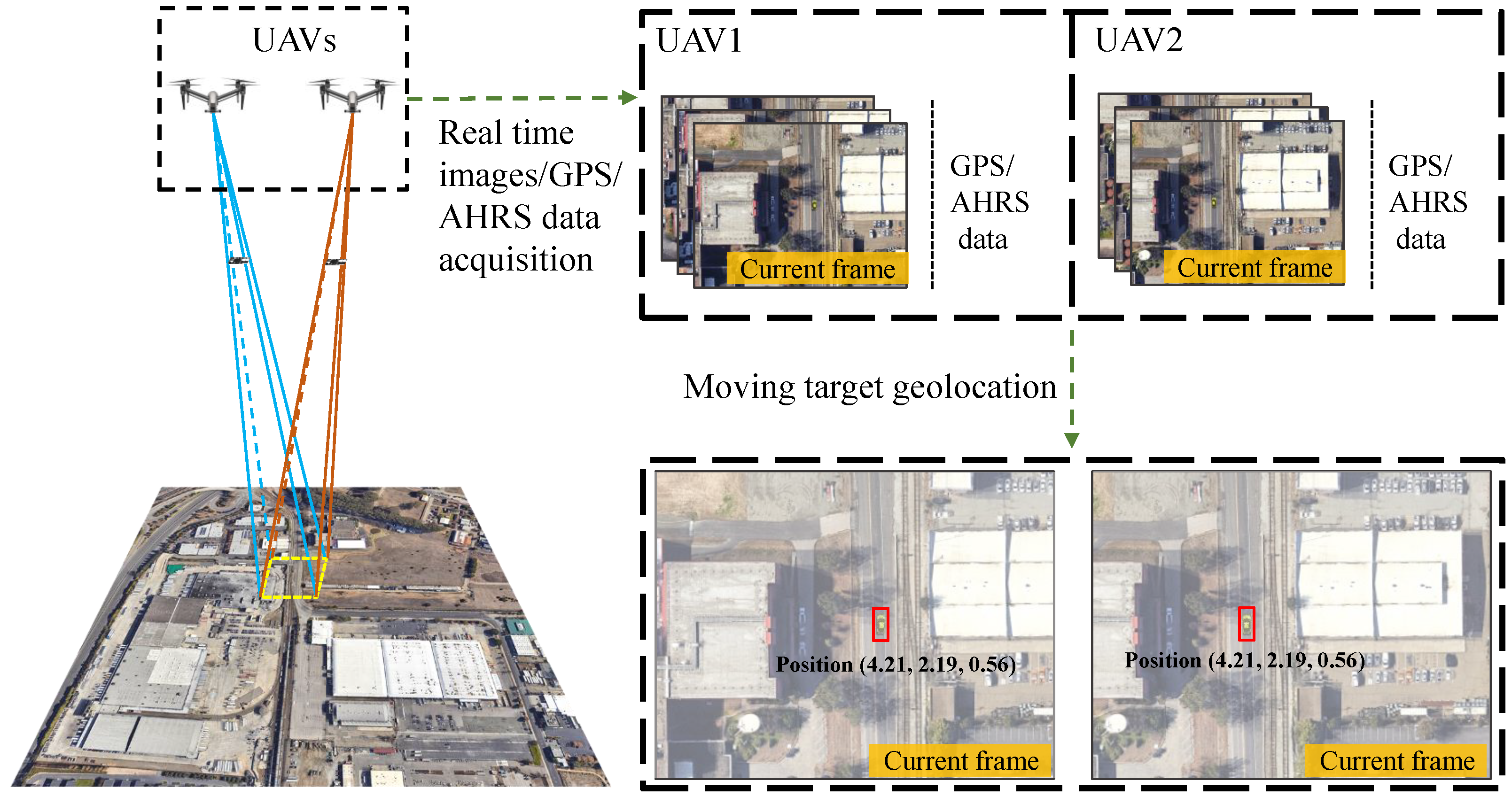
For simulation experiments, a moving target detection and tracking platform in an urban environment was built. In the platform, a vehicle runs in a city environment, as shown in Figure 6, and two UAVs with vertically downward cameras detect the target utilizing Yolov5 [27], as shown in Figure 7. The flight altitude of the two UAVs is 100 m, and the baseline between the two UAVs is 70 m. In the process of target sensing, the UAVs first use the target detection algorithm to find the target, and then use the proposed method to continuously geolocate the moving target. We implemented the proposed framework using Python and ran the framework on a machine with Intel(R) an i7-10700 @2.90 GHz CPU and NVIDIA RTX 2070 Super GPU.
Before geolocating the moving target using multiple images, including the past images, the corresponding points in the past images were matched using the corresponding-point-matching method described in Section 2.3. The accuracy of the corresponding-point-matching method proposed in this paper depends heavily on the estimation of the fundamental matrix F, and wrong corresponding point matching will cause an error in target geolocation. However, the estimation of the fundamental matrix is occasionally inaccurate due to the matching error of ORB features between the current image and the past image. Therefore, the method of filtering the wrong corresponding points is proposed in Section 2.3.
In order to evaluate the performance of the method for corresponding point matching and the effectiveness of the method for filtering the wrong corresponding points, we obtained the experimental results shown in Figure 8. In this experiment, we did not consider the influence of UAV navigation state measurement error on the geolocation results, but only observed the changes caused by the corresponding points. It is worth noting that eight images were used for each geolocation in this experiment. In Figure 8, the black line is the ground-truth path of the moving target, and the yellow line is the path estimated by the proposed moving-target geolocation framework without filtering the wrong corresponding points. It can be seen that the corresponding point matching introduces errors to the moving-target geolocation, and the geolocation error is large when the car is at the corner of an image, which is due to the small overlap between the current image and the past images, so there are not enough ORB features to estimate an accurate fundamental matrix. However, the geolocation error was greatly reduced after using the proposed method of filtering the wrong matching points, as shown by the red line.
The statistical characteristics of continuous geolocation results are shown in Table 1, in which we count the mean absolute errors (MAEs), the standard deviations (STDs), and the maximum errors (MAX) of geolocation results in each direction, X, Y, and Z. The mean absolute error (MAE) is calculated as follows:
M A E = i = 1 n y i y ^ i n
where n represents the number of geolocations, and y i and y ^ i represent the estimated value and the true value, respectively. It can be seen in Table 1 that the proposed method can effectively filter out the wrong corresponding points and reduce the geolocation errors.
After matching corresponding points, the past images and the current images are used to estimate the target’s altitude z P . We obtained the statistical characteristics of altitude estimation in the continuous geolocation process, as shown in Table 2. We utilized 4 or 8 images to obtain the altitude estimation results, and compared the mean absolute errors, the standard deviations, and the maximum errors of altitude estimation errors when using different numbers of images. In addition, we set σ ψ = σ θ = σ φ = 2 and σ x v = σ y v = σ z v = 3 m . The yaw-angle biases δ ψ L , δ ψ R of the left and right UAVs were set as follows:
δ ψ L = 0.2t + δ ψ 0 ; δ ψ R = 0.2t δ ψ 0
where t ( s ) represents the flight time of UAVs and δ ψ 0 was set to 20 in this experiment. It can be seen form the results shown in Table 2 that the more images used for target altitude estimation, the more accurate the altitude estimation will be. However, using more images means more computing costs, and the average processing speed of moving-target geolocation was 22 FPS when utilizing eight images and the above-mentioned machine in the realistic experiment.
Similarly to the experiments of target altitude estimation, we evaluated the performance of yaw-angle bias estimation. In this experiment, the true values of yaw-angle biases need to be known in order to evaluate our method, but it is difficult to measure the yaw-angle biases of a sensor in actual flight. Therefore, we set the same experimental conditions as the altitude estimation experiment to evaluate the performance of yaw-angle biases’ estimation in the simulation environment. As shown in Table 3, the same conclusion can be obtained—that is, the proposed method can effectively estimate the yaw-angle biases of UAVs, and the more images used, the more reliable the estimation results will be.
In the proposed framework, the altitude of a moving target and the yaw-angle biases of two UAVs are estimated iteratively until the preset conditions are reached. We preset two conditions for stopping the iteration. One is that the estimated yaw-angle biases of the current iteration are less than 0.1, and the other is that the maximum number of iterations is reached, and we set the maximum number of iterations to 20 in this study. Table 4 shows the average absolute errors of the estimated values in the iteration process of the proposed framework utilizing eight images under the above-mentioned experimental settings. It can be seen that when the number of iterations is four, the estimated yaw-angle biases and target altitude reach stable values. After that, the results of subsequent iterations fluctuate around the stable values. This is because in the iteration process, there is not only the influence of yaw-angle biases, but also the influence of Gaussian measurement errors. This makes it impossible for the whole system to reach a minimum yaw-angle biases through multiple iterations.
The main factors that affect the geolocation accuracy are the measurement errors of the UAV’s navigation state. Therefore, we evaluated the performance of the proposed framework under different measurement errors of the UAV’s attitude angle and position. As the comparison algorithm, the one-shot method assumes that the distance from UAV to the moving target is known (e.g., provided by laser rangefinder) and utilizes only one image to estimate the three-dimensional coordinates of the moving target. This approach assumes that the UAV navigation state is provided by an accurate AHRS, so it does not consider the influence of the UAV navigation state measurement errors on the geolocation result. We first assume that only the attitude angle has Gaussian measurement error in the UAV’s navigation state, and then compares the performance of the proposed framework and the one-shot method. Specifically, we set σ ψ = 1 , , 5 , respectively, and σ ψ = σ θ = σ φ . In the comparisons, we compared the three-dimensional geolocation errors and the distance error, as shown in Figure 9. It should be noted that the distance error is the distance between the estimated three-dimensional position and the true three-dimensional position.
The proposed framework utilizes 4 or 8 images to obtain the geolocation results for each geolocation. It can be seen that with an increase in attitude-angle measurement errors, the geolocation errors obtained by the two methods increase. In terms of the x coordinate and y coordinate, the geolocation errors of our method are always smaller than those of the one-shot method. This is because the proposed framework can expand the measurement data by corresponding point matching, and more measurement data can mitigate the negative influence of Gaussian measurement errors. In the same way, for the proposed framework, the geolocation results obtained by using eight images are more stable than those obtained by using four images. However, in terms of z coordinate, the geolocation error of our method is larger than that of the one-shot method. There are two reasons for this phenomenon. On the one hand, the target’s altitude z P is calculated according to the distance between the UAV and the moving target, and the true distance is assumed to be known for the one-shot method. On the other hand, the altitude estimation method described in Section 2.2 regards the point closest to the two lines of sight as the target point. The geolocation error caused by attitude measurement errors is more concentrated on the target altitude because the horizontal distance between the UAV and the target is much smaller than the vertical distance. Finally, the distance error of our method with eight images is smaller than that of the one-shot method, because the distance error contains the three-dimensional errors.
Then, we assumed that only the position has Gaussian measurement error in the UAV’s navigation state, and then compared the performance of the proposed framework and the one-shot method. Specifically, we set σ z = 1 m , , 5 m , respectively, and σ x = σ y = σ z . In the comparisons, we compare the three-dimensional geolocation errors and the distance error, as shown in Figure 10. The same conclusion can be obtained; that is, our method can greatly mitigate the impact of Gaussian measurement errors on the geolocation results due to the using of the historical measurement data. The difference is that our method with eight images is better than the one-shot method in terms of z coordinate. There are two reasons for this phenomenon. On the one hand, the influence of UAV’s position measurement error is greater than that of attitude measurement error for the one-shot method. On the other hand, the proposed framework can mitigate the negative influence of Gaussian measurement error by using weighted least-squares. In terms of distance error, our method is superior to the one-shot method, no matter whether four images or eight images are used.
After that, we assume that both the position and the attitude angle have Gaussian measurement error in the UAV’s navigation state, and then compare the performance of the proposed framework and the one-shot method. Specifically, we set σ z = 1 m , , 5 m , σ ψ = 1 , , 5 , respectively, and σ x = σ y = σ z , σ ψ = σ θ = σ φ . It can be seen in Figure 11 that our method with eight images has better mitigation effects on the negative influence of various Gaussian measurement errors. In this experiment, the assumption of measurement errors is consistent with most application scenarios. Even if the yaw-angle bias is not considered, the proposed framework is better than the one-shot method in practical applications.
In addition to the Gaussian measurement errors, the yaw-angle biases provided by the low-quality sensors also affect the geolocation results. Therefore, we assume that the navigation state has both Gaussian measurement errors and yaw-angle biases, and compare the performances of the proposed method and the one-shot method at different yaw-angle biases. In detail, we set σ ψ = σ θ = σ φ = 2 and σ x = σ y = σ z = 3 m . The yaw-angle biases δ ψ L , δ ψ R of the left and right UAVs are set as (34). We set δ ψ 0 to 10, 15, 20, 25, and 30, respectively, and then compared the performances of the two methods. It is shown in Figure 12 that the geolocation accuracy of the one-shot method is greatly reduced when there is bias in yaw-angle measurement, and as the yaw-angle measurement bias increases, the geolocation accuracy of the one-shot method becomes lower and lower. Compared with the one-shot method, the accuracy of our method does not change significantly as the yaw-angle measurement bias increases. This is because our method can estimate the yaw-angle bias through the iterations between the estimation of the target’s altitude and the parameter regression to avoid the negative impact of the yaw-angle measurement bias on geolocation accuracy. However, in terms of z-coordinate error, the accuracy of both methods has no obvious change as yaw-angle bias increases. There are two reasons for this phenomenon. On the one hand, the one-shot method assumes that the distance between the UAV and the moving target is known and the yaw-angle measurement error has little impact on the target’s altitude estimation. On the other hand, the proposed framework can eliminate the negative influence of the yaw-angle biases by utilizing the iterations between the processes of altitude estimation and parameter regression.
In conclusion, we first verified the effectiveness of the proposed corresponding-point-matching method, target altitude estimation method, and yaw-angle bias estimation method in the simulation environment. In addition, we conducted a lot of simulation experiments to verify the effectiveness and robustness of the proposed framework, and the simulation experiments showed that the geolocation results of the proposed framework are more accurate and stable under Gaussian measurement errors and yaw-angle biases compared with the commonly used one-shot method.

3.2. Evaluation in Real Environment

A real indoor experiment has also been performed to further validate the proposed framework. The UAVs used in this experiment were a laboratory product designed by our group, as shown in Figure 13a. A camera waws installed vertically downward on each UAV, so the attitude of the camera could be known from the attitude of the UAV. The two UAVs tracked the moving target, as shown in Figure 13b, and transmitted their pose information and target images to the ground station in real time. The two UAVs and the ground station were run in the ROS system, and the precise position and attitude information of the UAVs were provided by VICON (a motion capture system).
The important experimental parameters are shown in Table 5. The results of the realistic experiment are shown in Table 6. A total of 147 geolocation estimates were performed while the UAVs were tracking the moving target. Each geolocation needed to use eight images, among which, the distance between two adjacent images should satisfy T r e 0.25 m. This shows that our method successfully achieved the geolocation of the moving target, and the absolute mean errors of the three coordinates were 0.035, 0.034, and 0.159 m, respectively. When taking advantage of eight images for geolocation, the FPS was 22, which still meets the real-time requirements.
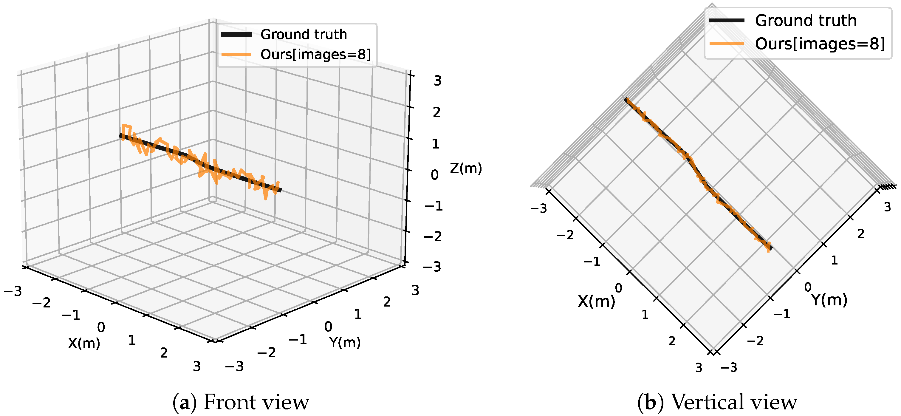
The geolocation path of the realistic is shown in Figure 14. The black path represents the actual position of the moving target obtained from VICON. The yellow path represents the position of the moving target obtained from our method. It can be seen that the path obtained by our method is undulating due to the influence of Gaussian measurement error of the UAV’s navigation state. The above-mentioned simulation experiments have demonstrated that our method can mitigate the effects of Gaussian measurement errors by utilizing the historical measurements.
The simulated and realistic experiments show that the proposed framework implements the function of geolocating the moving target using only UAV vision and does not rely on the accurate AHRS. Compared with the commonly used one-shot method, the proposed framework can mitigate the effects of measurement errors in a UAV’s position and attitude by using multiple measurement data and estimating the yaw-angle biases.

4. Discussion

In order to solve the problem that Gaussian measurement errors and system measurement errors of UAV state will lead to a decline in moving-target geolocation accuracy, we proposed a moving-target geolocation framework based on two UAVs. Our method uses a two-step strategy to obtain the final result. The accuracy of the final result depends on three aspects: the matching accuracy for the corresponding points, the accuracy of estimating target altitude, and the accuracy of estimating yaw-angle biases. It can be seen in the experimental results shown in Figure 8 and Table 1 that the proposed corresponding-point-matching method and error-corresponding-point-filtering method can enable historical measurement data to be used to estimate the current position of a moving target. In the subsequent processing step, our method obtains the final result through multiple iterations between target altitude estimation and yaw-angle bias estimation. The experimental results shown in Table 2 and Table 3 demonstrate that our method can estimate the target altitude and yaw-angle biases, and the more measurement data are used, the more accurate the estimated target altitude and yaw-angle biases will be. Even so, due to the influence of Gaussian measurement errors, it is still difficult for the proposed framework to accurately estimate the yaw-angle biases, which will be one of the directions of our future exploration.
After that, we evaluated the geolocation performance of the proposed method. For Gaussian measurement errors, obtaining more measurement data is the most effective method to mitigate the influence of Gaussian measurement errors. However, we do not simply increase the number of UAVs to obtain more observation data. If so, the cost will be higher and the system will be extremely complex. Our strategy is to have historical measurement data used to estimate the current position of the moving target through corresponding point matching. From the experimental results in Figure 9, Figure 10 and Figure 11, we can see that our method can mitigate the influence of Gaussian measurement errors very well. In contrast, the one-shot method is easily affected by the Gaussian measurement error because it can only use one measurement datum. For yaw-angle biases, our strategy is to eliminate the negative impact of yaw-angle biases through multiple iterations between target altitude estimation and yaw-angle bias estimation. The experimental results in Figure 12 show that our method can greatly mitigate the impact of yaw-angle biases on geolocation results compared with the one-shot method, which does not consider yaw-angle biases. It is worth noting that Zhang et al. [24] also considered the influence of yaw-angle biases on target geolocation, but their method assumes that the target is stationary. Unlike this, our method can be applied to moving-target geolocation.
In practical applications, the state measurement error of UAV is an important factor affecting the geolocation accuracy of moving-target tracking. The experimental results show that the proposed method can effectively mitigate the influence of UAV state measurement error on moving-target geolocation accuracy. However, the limitation of our method is that corresponding point matching requires the use of image background information, which is difficult to achieve in some scenes with simple background information (such as the geolocation of a moving target on the sea). Therefore, our next research plan is to develop a more general geolocation method.

5. Conclusions

In this paper, we explored the problem of moving-target geolocation based on a UAV platform with low-quality navigation state sensors. Our aim was to mitigate the influences of Gauss measurement errors and yaw-angle measurement bias from low-quality sensors on the moving-target geolocation accuracy. For this challenge, we proposed a vision-based moving-target geolocation framework using dual UAVs, which can use historical measurement data to estimate the yaw-angle biases of two UAVs and mitigate the impact of Gaussian measurement errors. The results of the simulations and realistic experiments demonstrate that the proposed framework has higher geolocation accuracy than the traditional one-shot based method.
The framework proposed in this paper is only applicable to single target geolocation scenarios. However, multi-target geolocation based on the UAV platform is also one of the urgent needs in practical applications. Therefore, in future work, we will develop a more general geolocation method.

Author Contributions

Conceptualization, B.D. and J.G.; methodology, T.P.; software, T.P.; validation, J.G.; formal analysis, H.D.; investigation, H.D. and B.Z.; resources, T.P.; data curation, J.G.; writing—original draft preparation, T.P.; writing—review and editing, J.G. and H.D.; visualization, T.P.; supervision, B.D.; project administration, B.D.; funding acquisition, B.D. All authors have read and agreed to the published version of the manuscript.

Funding

This research was funded by National Natural Science Foundation of China, grant number 61472095 and 61902423.

Data Availability Statement

The data presented in this study are available on request from the corresponding author.

Conflicts of Interest

The authors declare no conflict of interest.

References

  1. Potena, C.; Khanna, R.; Nieto, J.; Siegwart, R.; Nardi, D.; Pretto, A. AgriColMap: Aerial-ground collaborative 3D mapping for precision farming. IEEE Robot. Autom. Lett. 2019, 4, 1085–1092. [Google Scholar] [CrossRef]
  2. Yuan, Y.; Fang, F.; Zhang, G. Superpixel-based seamless image stitching for UAV images. IEEE Trans. Geosci. Remote Sens. 2020, 59, 1565–1576. [Google Scholar] [CrossRef]
  3. Zhang, F.; Yang, T.; Liu, L.; Liang, B.; Bai, Y.; Li, J. Image-only real-time incremental UAV image mosaic for multi-strip flight. IEEE Trans. Multimed. 2020, 23, 1410–1425. [Google Scholar] [CrossRef]
  4. Gautam, D.; Lucieer, A.; Bendig, J.; Malenovskỳ, Z. Footprint determination of a spectroradiometer mounted on an unmanned aircraft system. IEEE Trans. Geosci. Remote Sens. 2019, 58, 3085–3096. [Google Scholar] [CrossRef]
  5. Zhao, X.; Pu, F.; Wang, Z.; Chen, H.; Xu, Z. Detection, tracking, and geolocation of moving vehicle from uav using monocular camera. IEEE Access 2019, 7, 101160–101170. [Google Scholar] [CrossRef]
  6. Tang, D.; Fang, Q.; Shen, L.; Hu, T. Onboard detection-tracking-localization. IEEE/ASME Trans. Mechatronics 2020, 25, 1555–1565. [Google Scholar] [CrossRef]
  7. Deng, F.; Zhang, L.; Gao, F.; Qiu, H.; Gao, X.; Chen, J. Long-range binocular vision target geolocation using handheld electronic devices in outdoor environment. IEEE Trans. Image Process. 2020, 29, 5531–5541. [Google Scholar] [CrossRef] [PubMed]
  8. Yang, X.; Lin, D.; Zhang, F.; Song, T.; Jiang, T. High accuracy active stand-off target geolocation using UAV platform. In Proceedings of the 2019 IEEE International Conference on Signal, Information and Data Processing (ICSIDP), Chongqing, China, 11–13 December 2019; pp. 1–4. [Google Scholar]
  9. Cai, Y.; Ding, Y.; Zhang, H.; Xiu, J.; Liu, Z. Geo-location algorithm for building targets in oblique remote sensing images based on deep learning and height estimation. Remote Sens. 2020, 12, 2427. [Google Scholar] [CrossRef]
  10. Fabian, A.J.; Klenke, R.; Truslow, P. Improving UAV-Based Target Geolocation Accuracy through Automatic Camera Parameter Discovery. In Proceedings of the AIAA Scitech 2020 Forum, Orlando, FL, USA, 6–10 January 2020; p. 2201. [Google Scholar]
  11. Liu, C.; Liu, J.; Song, Y.; Liang, H. A novel system for correction of relative angular displacement between airborne platform and UAV in target localization. Sensors 2017, 17, 510. [Google Scholar] [CrossRef] [PubMed]
  12. El Habchi, A.; Moumen, Y.; Zerrouk, I.; Khiati, W.; Berrich, J.; Bouchentouf, T. CGA: A new approach to estimate the geolocation of a ground target from drone aerial imagery. In Proceedings of the 2020 Fourth International Conference On Intelligent Computing in Data Sciences (ICDS), Fez, Morocco, 21–23 October 2020; pp. 1–4. [Google Scholar]
  13. Namazi, E.; Mester, R.; Lu, C.; Li, J. Geolocation estimation of target vehicles using image processing and geometric computation. Neurocomputing 2022, 499, 35–46. [Google Scholar] [CrossRef]
  14. Xu, C.; Huang, D.; Liu, J. Target location of unmanned aerial vehicles based on the electro-optical stabilization and tracking platform. Measurement 2019, 147, 106848. [Google Scholar] [CrossRef]
  15. Bai, G.; Liu, J.; Song, Y.; Zuo, Y. Two-UAV intersection localization system based on the airborne optoelectronic platform. Sensors 2017, 17, 98. [Google Scholar] [CrossRef] [PubMed]
  16. Carniglia, P.; Balaji, B.; Rajan, S. Geolocation of mobile objects from multiple UAV optical sensor platforms. In Proceedings of the 2018 IEEE SENSORS, New Delhi, India, 28–31 October 2018; pp. 1–4. [Google Scholar]
  17. Xu, C.; Yin, C.; Han, W.; Wang, D. Two-UAV trajectory planning for cooperative target locating based on airborne visual tracking platform. Electron. Lett. 2020, 56, 301–303. [Google Scholar] [CrossRef]
  18. Qiao, C.; Ding, Y.; Xu, Y.; Xiu, J. Ground target geolocation based on digital elevation model for airborne wide-area reconnaissance system. J. Appl. Remote Sens. 2018, 12, 016004. [Google Scholar] [CrossRef]
  19. Gao, F.; Deng, F.; Li, L.; Zhang, L.; Zhu, J.; Yu, C. MGG: Monocular Global Geolocation for Outdoor Long-Range Targets. IEEE Trans. Image Process. 2021, 30, 6349–6363. [Google Scholar] [CrossRef] [PubMed]
  20. Zhu, J.; Fang, Y. Learning Object-Specific Distance From a Monocular Image. In Proceedings of the 2019 IEEE/CVF International Conference on Computer Vision (ICCV), Seoul, Republic of Korea, 27 October–2 November 2019; pp. 3838–3847. [Google Scholar] [CrossRef]
  21. Wang, X.; Qin, W.; Bai, Y.; Cui, N. Cooperative target localization using multiple UAVs with out-of-sequence measurements. Aircr. Eng. Aerosp. Technol. 2017, 89, 112–119. [Google Scholar] [CrossRef]
  22. Xu, C.; Yin, C.; Huang, D.; Han, W.; Wang, D. 3D target localization based on multi–unmanned aerial vehicle cooperation. Meas. Control 2021, 54, 895–907. [Google Scholar] [CrossRef]
  23. Pachter, M.; Ceccarelli, N.; Chandler, P.R. Vision-based target geolocation using micro air vehicles. J. Guid. Control Dyn. 2008, 31, 597–615. [Google Scholar] [CrossRef]
  24. Zhang, L.; Deng, F.; Chen, J.; Bi, Y.; Phang, S.K.; Chen, X.; Chen, B.M. Vision-based target three-dimensional geolocation using unmanned aerial vehicles. IEEE Trans. Ind. Electron. 2018, 65, 8052–8061. [Google Scholar] [CrossRef]
  25. Zhang, L.; Deng, F.; Chen, J.; Bi, Y.; Phang, S.K.; Chen, X. Trajectory planning for improving vision-based target geolocation performance using a quad-rotor UAV. IEEE Trans. Aerosp. Electron. Syst. 2018, 55, 2382–2394. [Google Scholar] [CrossRef]
  26. Quigley, M.; Conley, K.; Gerkey, B.; Faust, J.; Foote, T.; Leibs, J.; Wheeler, R.; Ng, A.Y. ROS: An open-source Robot Operating System. In Proceedings of the ICRA Workshop on Open Source Software, Kobe, Hyogo, Japan, 12–17 May 2009; Volume 3, p. 5. [Google Scholar]
  27. Zhu, X.; Lyu, S.; Wang, X.; Zhao, Q. TPH-YOLOv5: Improved YOLOv5 Based on Transformer Prediction Head for Object Detection on Drone-captured Scenarios. In Proceedings of the 2021 IEEE/CVF International Conference on Computer Vision Workshops (ICCVW), Montreal, BC, Canada, 11–17 October 2021; pp. 2778–2788. [Google Scholar] [CrossRef]
Figure 1. Demonstration that the proposed framework realizes online ground moving-target geolocation using dual UAVs.
Remotesensing 15 00389 g001
Figure 2. Overview of the proposed moving-target geolocation framework using dual UAVs.
Remotesensing 15 00389 g002
Figure 3. Target geolocation model.
Remotesensing 15 00389 g003
Figure 4. Target altitude estimation model.
Remotesensing 15 00389 g004
Figure 5. Corresponding-point-matching model.
Remotesensing 15 00389 g005
Figure 6. Urban environment and moving path of the target in the GAZEBO simulation.
Remotesensing 15 00389 g006
Figure 7. Two UAVs track and detect the moving target.
Remotesensing 15 00389 g007
Figure 8. Paths of geolocation in the experiment of corresponding point matching.
Remotesensing 15 00389 g008
Figure 9. Geolocation errors under different measurement errors of attitude.
Remotesensing 15 00389 g009
Figure 10. Geolocation errors under different measurement errors of position.
Remotesensing 15 00389 g010
Figure 11. Geolocation errors under different measurement errors of attitude and position.
Remotesensing 15 00389 g011
Figure 12. Geolocation errors under different yaw-angle biases.
Remotesensing 15 00389 g012aRemotesensing 15 00389 g012b
Figure 13. Realistic experimental environment.
Remotesensing 15 00389 g013
Figure 14. Paths of geolocation.
Remotesensing 15 00389 g014
Table 1. Statistical results of geolocation in the experiment of corresponding point matching.
Before FilteringAfter Filtering
xyzxyz
MAE (m)0.2830.2741.2160.1510.1730.720
STD (m)0.3730.4081.5610.1250.1640.547
MAX (m)4.1356.3358.5740.6921.1352.464
Table 2. Statistical results of altitude estimation of the target.
Number of ImagesMAE ( m ) STD ( m ) MAX ( m )
43.3722.7699.812
82.4481.9317.819
Table 3. Statistical results of yaw-angle bias estimation.
Number of Images MAE ( deg ) STD ( deg ) MAX ( deg )
4 δ ψ L 7.6424.27013.943
δ ψ R 6.6333.47713.125
8 δ ψ L 3.0512.7817.099
δ ψ R 2.5502.1566.957
Table 4. Iterative process of parameter estimation.
Number of Iterations k12348121620
δ ψ L k ( d e g ) 16.372 4.269 2.812 2.753 2.841 2.912 2.736 3.051
δ ψ R k ( d e g ) 14.448 4.931 2.469 2.817 2.526 2.728 2.837 2.550
z P ( m ) 10.4485.9313.8192.7692.8152.6352.8642.448
Table 5. Experimental parameters.
Number of ImagesFlight AltitudeFlight Speed σ ψ σ z δ ψ L δ ψ R
82.8 m0.26 m/s 2 0.2 m 10 10
Table 6. Geolocation results.
CoordinateMAE ( m ) STD ( m ) MAX ( m )
X0.0350.0290.125
Y0.0340.0250.104
Z0.1590.1130.446
Disclaimer/Publisher’s Note: The statements, opinions and data contained in all publications are solely those of the individual author(s) and contributor(s) and not of MDPI and/or the editor(s). MDPI and/or the editor(s) disclaim responsibility for any injury to people or property resulting from any ideas, methods, instructions or products referred to in the content.

