1. Introduction
As one of the most destructive disasters, earthquakes occur more than one million times a year. A large number of people are exposed to the risks or hazards caused by earthquakes every year [
1,
2]. Taking the year 2021 only as an example, there were 115 earthquakes of magnitude 6 or higher around the world, of which 19 are earthquakes of magnitude 7 or higher. The most direct hazard caused by earthquakes is the damage or collapse of buildings, which results in substantial personnel casualties and property losses [
3]. After an earthquake, both structural and non-structural elements of buildings will be subject to varying degrees and forms of damage. Therefore, a damage assessment based on information about the destruction that occurred is an important prerequisite for post-earthquake reinforcement and repair. Reliable assessment results can not only provide references and guidance for the sustainable reinforcement and repair of post-earthquake buildings but also assist in the timely development of a sound rescue plan [
4].
There is much research on seismic risk evaluation using established mechanical models [
5,
6]. There are fewer studies on damage assessments of seismic buildings. Due to the limited development of damage assessment, visual inspection by expert surveyors is still an important traditional damage assessment method. However, the inspection results involve too much data and calculation, which is not suitable for mass assessment. Furthermore, the inspection results are heavily subjective, because some expert surveyors have different cognition and understanding of damage assessment criteria. Computer vision (CV) is a technology that integrates the management of acquired data from digital vision devices with computer hardware and software resources. Therefore, CV can realize image recognition efficiently using algorithm analysis, and alternatively use mathematical theory to indirectly calculate damage information. The functions of CV mentioned above can improve scientific (the objectivity of observations about damage detection and quantification) and real-time damage assessments simultaneously.
However, for post-earthquake buildings, damage assessment requires a combination of information involving many factors (such as building structure and soil characteristics around the building) [
7,
8]. Although there is much research on non-destructive testing methods using ultrasonic and sonic wave propagation to obtain material properties [
9,
10], many scholars use experiments and simulations to evaluate the damage and risk or reliability of structures considering the performance of buildings under the action of ground motions [
11,
12,
13,
14,
15]. It is difficult to guarantee the reliability of damage assessment results based on the information obtained with images and non-destructive testing results. Being a technology that can add virtual information to the real world, AR can supply more information to improve the scientific, universal, and visualization of the damage assessment.
A damage assessment often involves the type and quantity of the damaged information on the seismic component, which is difficult to obtain directly from the post-earthquake site. Therefore, this paper tried to combine AR and CV to obtain comprehensive information on post-earthquake buildings. However, AR cannot provide damage information directly. Thus, this paper introduced the grey value theory, which can obtain quantitative damage information using AR. To be specific, a shooting distance can be obtained using AR measures, and some quantitative damage information (such as the width of a crack) can be calculated using a combination of the shooting distance and the grey value of shooting images. It is expected that a corresponding relationship between the gray value and the image pixel can be established using an AR environment. In addition, this paper used AR to visually display the damage components’ information, and AR was also used to transfer and store information, including the damage information and damage components’ models [
16].
This paper proposed a method for the intelligent damage assessment of post-earthquake buildings. This method integrates CV and AR, which can improve visual inspection efficiently. Meanwhile, this intelligent damage assessment method can develop the objectivity, scientific, and visualization of the assessment results and make it easy to query and manage the damage information.
The contributions of this paper can be mainly concluded with three points: (1) Propose an intelligent damage assessment method that integrates CV and AR to realize an intelligent damage assessment. (2) Establish the transformation relationship from 3D coordinates to 2D image coordinates and 2D pixel coordinates, which supplies quantity information for a damage assessment. (3) As an innovative means of information collection, apply AR in the damage assessment of a post-earthquake building.
2. Literature Review
2.1. Damage Assessment of Post-Earthquake Buildings
Currently, two methods are mostly used for the damage assessment of post-earthquake buildings, which are site investigation and visual inspection by experts [
17]. Although these two methods are easy to use, they have significant shortcomings, such as being highly influenced by subjectivity, inefficiency in assessment, and difficulty to ensure the safety of assessment experts. Due to the differences in knowledge and experience held by different specialists, cognitive biases of these specialists may increase the uncertainty of damage assessment results. Undertaking multiple assessments to reduce the uncertainty of assessment results is time-consuming and labor-intensive [
18]. The FEMA (Federal Management Emergency Administration) of the United States [
19] first published “Rapid Visual Screening of Buildings for Potential Seismic Hazards: A Handbook” (FEMA154) in 1988. FEMA154 is proposed to satisfy the assessment needs of a fast, reliable, and simple calculation of damaged structures. FEMA154 performs a quick judgment of damaged structures in the form of scoring and classifies the damaged structures at different levels using the “score line” set by experts. Although FEMA154 has great guiding significance for damage assessment, it can only perform inspections from the exterior of the building, while the inspection accuracy mainly relies on the knowledge of experts.
With the development of information technology, especially the widely used UAV (Unmanned Aerial Vehicle) and 3D scanning of earthquake sites [
20,
21], damage assessments have also tended to become more intelligent. Wang et al. [
22] studied pavement crack detection techniques, and they found many problems in visual inspection and semi-automatic inspection. For example, the traditional inspection methods require far more manpower, material, and time resources than are practical. Furthermore, the speed and accuracy of detection are also difficult to estimate. In this research, Wang et al. conducted a study of the literature on crack image acquisition and crack image segmentation. The study compared the detection speed and accuracy of 12 algorithms for different crack images, which aimed to provide a reference for realizing the efficient and automatic detection of pavement cracks. Shakya et al. [
23] conducted a visual inspection of damaged buildings in Bhaktapur after the Gorkha (Nepal) earthquake. However, considering the impact on specialist safety due to aftershocks and road damage, they had to interrupt inspections several times.
2.2. Computer Vision for Damage Assessment
With the development of remote sensing technology and computer technology, damage assessment combined with CV can substantially break through the limitations of visual inspection. CV is characterized by high intelligence and precision, which makes it widely used for the inspection and detection of buildings and infrastructure [
24]. In general, CV is a science that uses camera recognition and algorithm analysis to reduce the subjective fallacies of observers [
25].
The essence of damage assessment is damage classification. In the background of the rapid development of CV, more and more algorithms are introduced into CV to improve the speed and accuracy of damage assessment. As one of the most popular machine learning algorithms, SVM (Support Vector Machine) is widely used in classification. Fayed and Atiya et al. [
26] used SVM to classify various handwriting datasets. However, SVM can only achieve binary classification. So, it was necessary for their experiment to transform the classification of handwriting into a problem of binary classification. Although the accuracy of the classification of handwriting was found to be as high as around 99% in their experiment, SVM may be not suitable for multi-classification problems. In addition, random forest is also used extensively for damage classification as it has the advantages of simple implementation, high accuracy, and resilience to over-fitting. Shanmugam et al. [
27] proposed a method for the automatic classification of glaucoma using deep learning and random forest. The accuracy of the proposed method was as high as 99%. However, random forest requires separate feature extractors to extract manually defined features (such as size and shape, etc.). Therefore, random forest may be not suitable for the damage assessment of post-earthquake buildings.
CNNs are one of the most representative deep learning algorithms, which has significant advantages for damage recognition [
28]. CNNs can not only extract features automatically but also have a strong self-learning capability. In addition, CNNs can be used for both binary classification and multi-classification [
29,
30]. Cha et al. [
31] conducted crack classification experiments on multiple photographs using CNN with an accuracy of 97.42%. Botta et al. [
32] took 468 eggshell photos and then developed a dataset of image patches. They used a CNN and SVM to classify the image patches into “Crack” and “Intact” datasets. The experimental data collected by Botta et al. showed that the CNN model had an accuracy rate of 95.38% in eggshell image classification, which performed better than the SVM model. Bai et al. [
33] proposed a method for optimizing the inspection of railway fasteners. This method used a modified Faster R-CNN (Region-Convolutional Neural Network) to recognize four different types of fasteners. The results showed that Faster R-CNN performed well in multi-classification. These studies mentioned above illustrate that CNNs can not only solve multi-classification problems but also have high classification accuracy.
2.3. Augmented Reality in Construction
Due to the specificity and complexity of earthquakes, the results of damage assessments of buildings after an earthquake are often influenced by many factors. To improve the reliability of the assessment results, multiple types of information are usually required before a damage assessment [
34]. However, traditional data collection methods make it difficult to ensure both the accuracy and comprehensiveness of post-earthquake building information. Therefore, this paper uses AR to assist CV when collecting earthquake site information. Moreover, AR also allows for immersive reading and visual display of the collected information [
35,
36]. Garbett et al. [
37] developed a BIM (Building Information Model)-AR damage assessment system for the design and construction process of buildings. This system enabled real-time transmission of information and simultaneous communication among different users. The ultimate purpose of this system was to realize multi-user collaborative work in architectural design and construction using real-time communication. Liu et al. [
16] proposed a method for post-earthquake retrofitting visualization of buildings using both AR and BIM. This method used the advantages of AR and BIM to realize the multi-level expression of seismic damage components. By integrating multi-dimensional information of seismic damage components, the multi-level information can provide guidance for subsequent retrofits. This method also promoted collaboration among builders.
3. The Fusion Mechanism of CV and AR in an Intelligent Damage Assessment
This section focuses on the methodology and mechanism of intelligent damage assessments of post-earthquake buildings using CV and AR. The deep learning algorithms built into CV can perceive the pixels of images, which is called image recognition. Image recognition is used to classify different image patterns into different image sets. The aim of image recognition is to classify different damage types into different sets. However, a damage assessment of post-earthquake buildings cannot be realized simply by identifying image patterns. Therefore, this paper expects to complement and refine the science and visualization of damage assessment by introducing AR.
In the intelligent damage assessment method proposed in this paper, the assessment process seems like a ‘black box’ (as shown in
Figure 1). To obtain the quantitative relationship of damaged information using a gray value, as a supplementary technology, AR can collect more earthquake site information to input into the ‘black box’ for an intelligent damage assessment. The images collected from the earthquake site with sensors can also synchronously transmit into the ‘black box’. The deep learning algorithm and gray value principle included in the ‘black box’ can analyze and calculate these images and data information, which aims to achieve the assessment of damaged buildings. After a damage assessment, the damage information (including damage data and damage models) will be displayed in the terminal.
The information obtained from earthquake site sensors (such as UAV) will input images into the ‘black box’ for image recognition. AR can supplement virtual data, which is called AR data. In addition, AR data does not exist in the physical world. The main purpose of AR data is to supply the original data for coordinate transformation between 2D and 3D, which aims to obtain the quantity information for a damage assessment. After receiving the sensor information, the AR data are analyzed and processed in the ‘black box’. At this time, the quantity information and type information are all in the ‘black box’, waiting to be used in a damage assessment. Finally, AR can visually display the results of a damage assessment. The intelligent assessment method proposed in this paper is to analyze the information simply twice. First, the image and shooting distance information are analyzed for image recognition and grey value calculation. Second, the fused information, including the results of the image recognition and grey value calculation, is analyzed for the damage assessment. At the same time, the real-time dynamic damage assessment of seismic damaged components in post-earthquake buildings is completed, and the results of the assessment are ready for visual display.
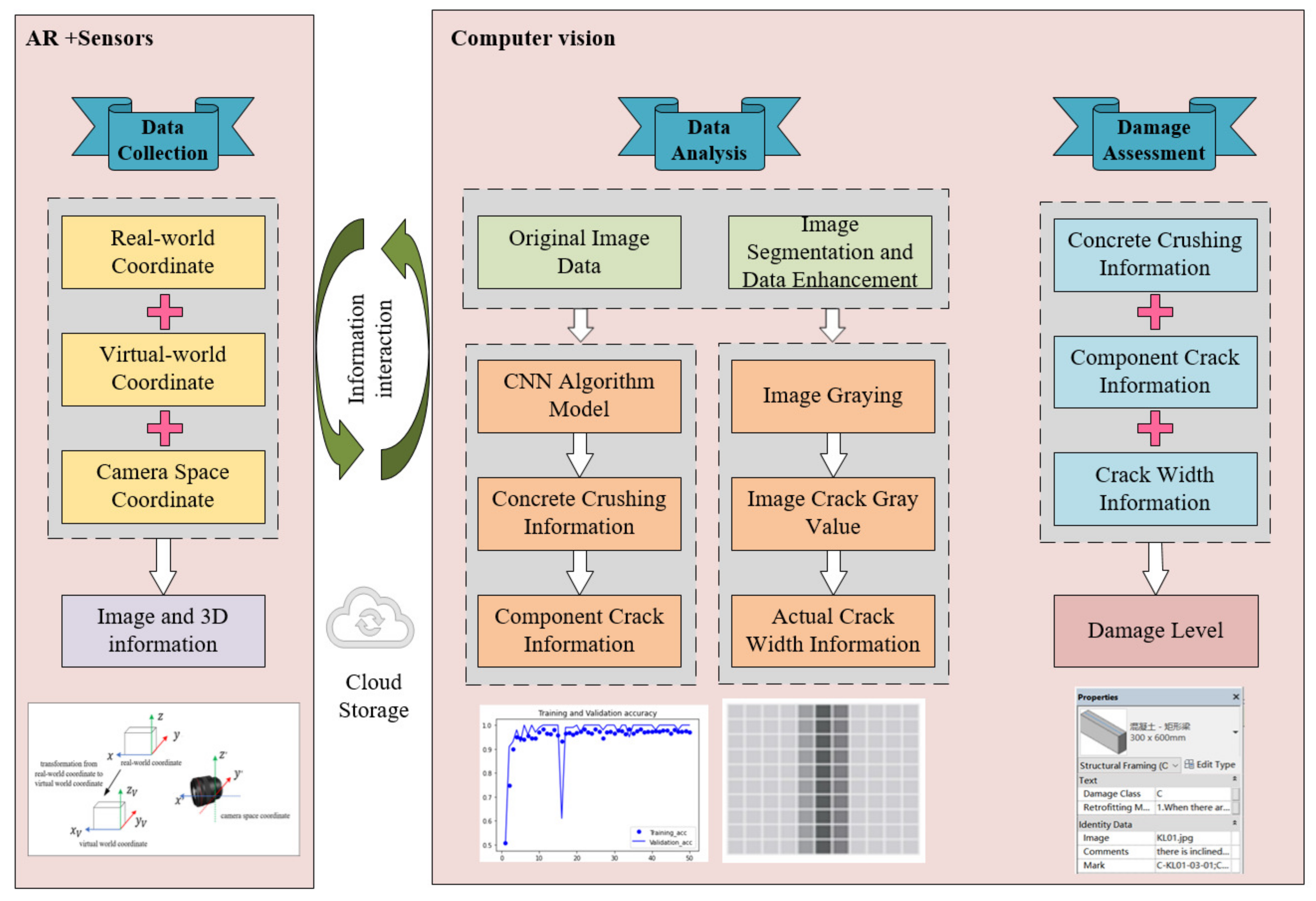
The proposed method in this paper uses AR to dynamically enhance virtual data with 3D information, including shooting distance, into the real world. Then, the AR data and images are input into a ‘black box’ to obtain the fusion data (the detailed type of damage information and quantitative damage information). Moreover, the results of the damage assessment are expressed as damage classes by comparing the fusion data with damage assessment regulations. The damage information can also be visually displayed in the AR terminal. The fusion mechanism of CV and AR in the damage assessment is shown in
Figure 2.
As is shown in
Figure 2, intelligent damage assessment starts with the use of sensors (such as UAV) and AR technology to obtain original data. The 3D information (including shooting distance) is measured by the conversion between the coordinates. Image segmentation and data augmentation are required for the original images, and then, the pre-processed images should be recognized by a CNN. Meantime, the AR data should be calculated using a gray value. After obtaining the type and quantity information (such as the information about the type and width of the crack) of the seismic components, the damage class can be assessed using the damage assessment principle. The damage information and assessment results can be displayed using the AR terminal as well.
4. A Combined CV and AR Method for Damage Assessment
4.1. Process of Intelligent Damage Assessment
The intelligent damage assessment of post-earthquake buildings is the classification of seismic components according to their damaged state. The results of a damage assessment are influenced by many factors, and the criteria for damage assessment are not identical for different structures. In order to harmonize damage assessment criteria, ‘Technical Specification for Post-earthquake Urgent Assessment and Repair of Buildings’ is chosen as the regulation of intelligent damage assessment [
38]. Taking the RC (Reinforced Concrete Frame) beam as an example, the damage class can be used to indicate the state of damage. The specific content is shown in
Table 1.
(1) Class A: Class A means that there is no damage to the frame beam, or the damage is so minimal that it does not affect the safety, applicability, and durability of the structure at all. Specifically, the components do not require repair or modification. For example, when the RC beam is unbroken concrete and non-cracked, the result of the damage assessment will be defined as Class A.
(2) Class B: Class B means that there has been some damage to the structure, but these damages have a limited impact on the performance of the structure. For example, when the RC beam is unbroken concrete with only a diagonal crack or cross crack, and the crack width is less than 0.5 mm, the result of the damage assessment is Class B.
(3) Class C: Class C means that the damage to the structure will affect its performance, and this damage may be modified. After the modification, the performance of the structure can be restored even better than before reinforcing. For example, when the RC beam is unbroken concrete with only a diagonal crack or cross crack, and the crack width is over or equal to 0.5 mm, the result of the damage assessment is Class C.
As shown in
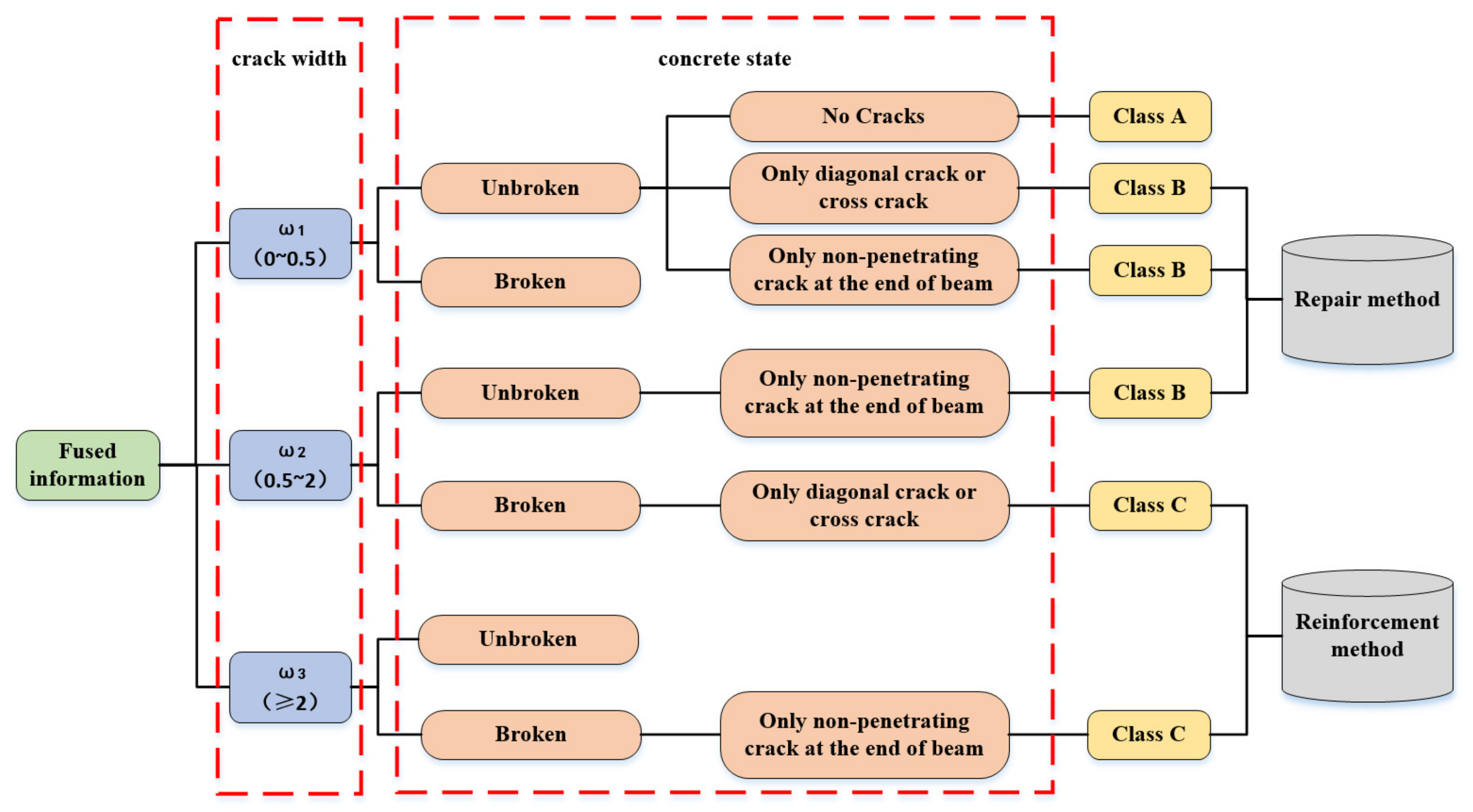
Table 1, the damage class is determined by the crack state and concrete state. The damage types of cracks and concretes can be classified using image recognition. The crack width is calculated using the gray value theory. Taking the damage assessment of RC beams as an example, the specific assessment process of damaged components is shown in
Figure 3.
As shown in
Figure 3, a complete damage assessment process requires information on the type information and the quantity information, which is called fused information. Taking the RC beams as an example, the damage assessment process can be divided into two parts: the first part aims to calculate the crack width using the gray value theory [
39]; the second part aims to complete the classification of damage types of the concrete condition and crack shape (for example, whether the concrete is broken, whether there are cracks in the components). The damage class is determined by synthesizing the quantitative damage information and damage type information. When the concrete of an RC beam is not broken and there is only a diagonal crack or cross crack with a width of 0.5~2 mm, the class of the damage assessment is Class C, which means the damaged components need to be reinforced. According to the definition of the damage class, many appropriate reinforcement methods can be selected for subsequent reinforcement and retrofitting.
4.2. Information Collection and Display of Post-Earthquake Buildings Using Augmented Reality
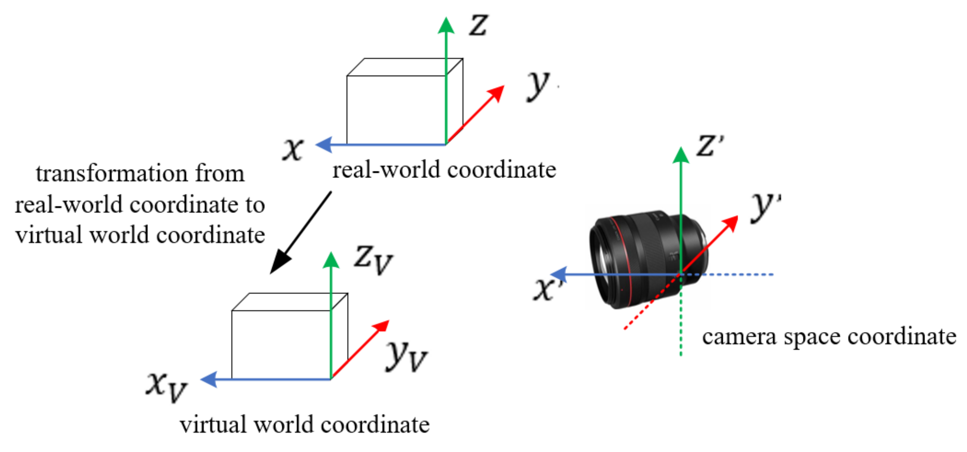
AR is used in the information collection and display based on the coordinate transformation between the virtual world and the real world. Therefore, virtual–real fusion is the key to AR. Virtual–real fusion is achieved by the transformation of coordinates, which is called registration. One of the most mature registration technologies is Fiducial Marker, which is used in this paper. Fiducial Marker involves three coordinate transformations: real-world coordinate, virtual world coordinate, and camera space coordinate [
40,
41]. The transformation relationship of these three coordinates is shown in
Figure 4.
The coordinates of the virtual world are determined by the position of the virtual object in the real world so that both the coordinates of the real world and the coordinates of the virtual world are known. The main transformation relations of the three coordinates are as follows:
where
is the real-world coordinate,
is the virtual world coordinate, and
is the transformation relationship between the real-world coordinate system and the virtual world coordinate.
where
is the camera space coordinate;
is the orthogonal identity matrix, which indicates the direction of the camera in the real-world coordinate;
is a 3D vector, which indicates the position of the camera in the real-world coordinate; and
is the transformation relationship between the camera space coordinate and the real-world coordinate.
The transformation relationship between the real-world coordinate and the virtual world coordinate is known, which means
is known. Thus, obtaining
is the key to realizing coordinated transformation.
is a transformation matrix, which means
can be converted into a combination of a rotation matrix
and a translation matrix
. The specific matrix conversion combination is shown in Equation (3).
Rotation matrix
and translation matrix
can be obtained with attitude sensors, gyroscope sensors, and positioning sensors embedded in the camera [
42].
4.3. Calculating the Quantitative Information Using Gray Value Theory
The gray value is a kind of mathematical morphology, which is widely used in image processing. Mathematical morphology is based on geometry, which uses structural elements to find the shape features of objects in an image. Because many damages (such as cracks) are not binary images, this paper selected the grayscale morphology combined with corrosion, expansion, and opening and closing operations for image preprocessing.
The corrosion calculation of the non-flat structural element
on the image
at the position
is:
The specific operation of corrosion in grayscale morphology involves superimposing the structural elements on an area of the same shape in the image, and then, respectively, calculating the gray value of each image point and taking the minimum value as the final gray value. The processing is completed after traversing each region of the image.
The expansion calculation of the structural element
on the image
at the position
is:
The specific operation of expansion in grayscale morphology is the same as that for the expansion calculation except expansion takes the maximum value as the final gray value.
If all the elements of
are constant, the above formula can be simplified as:
The opening and closing calculations are:
The purpose of coordinate transformation in
Section 4.2 is to place the virtual object in the physical world. It is impossible to measure all the quantitative information (such as crack width) directly. Therefore, on the basis of
Section 4.2, it is also necessary to transform information among the camera space coordinate, image coordinate, and pixel coordinate.
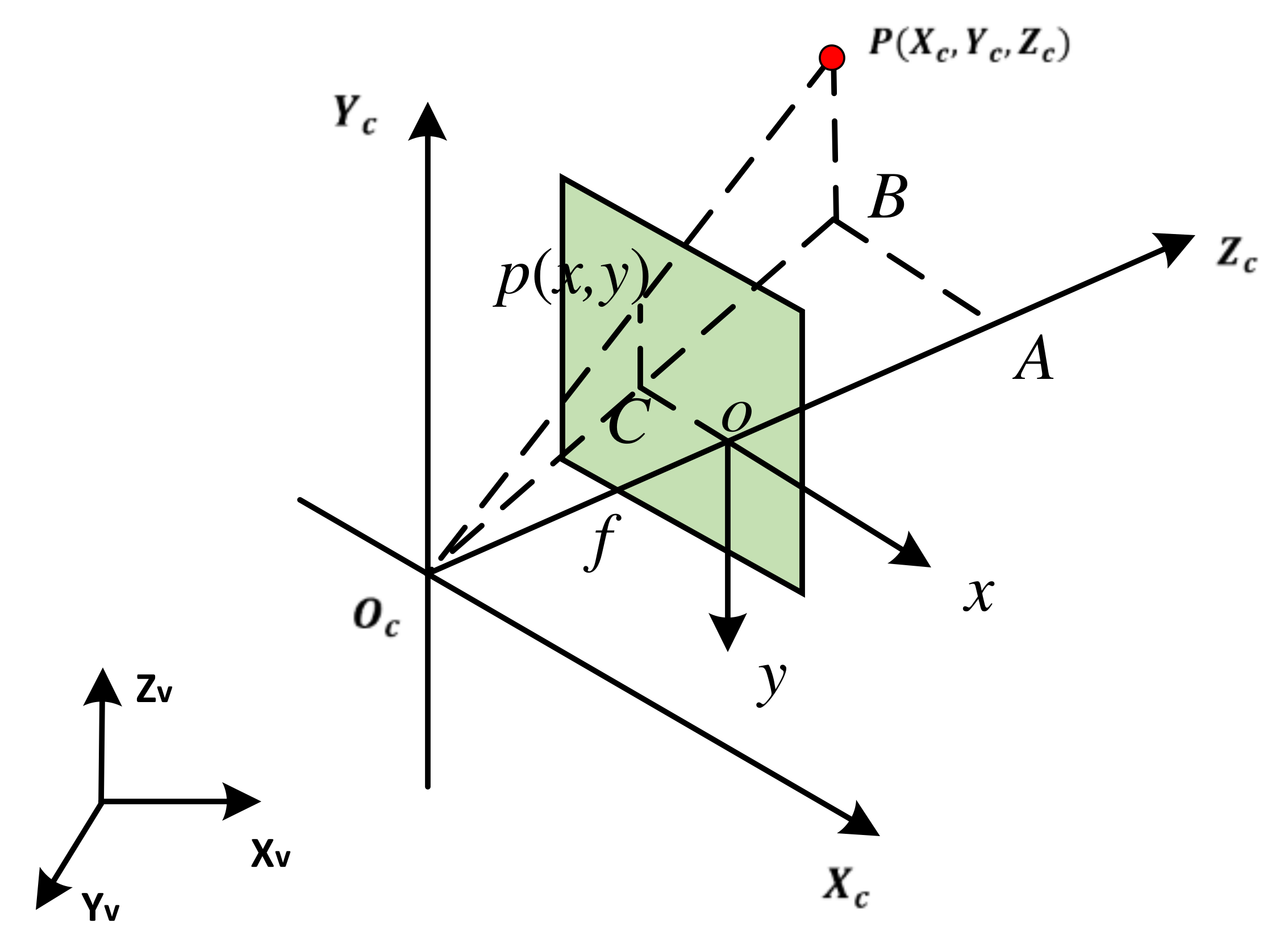
The transformation of the camera coordinates to the image coordinates is the transformation from 3D to 2D, as shown in
Figure 5:
According to the triangle similarity principle:
where
is the camera optical center,
is the camera optical axis, and
is the camera focal length
:
The expression in matrix form is:
where
,
,
is the magnification factor from an image coordinate to a pixel coordinate on the
axis, and
is the magnification factor from an image coordinate to a pixel coordinate on the
axis.
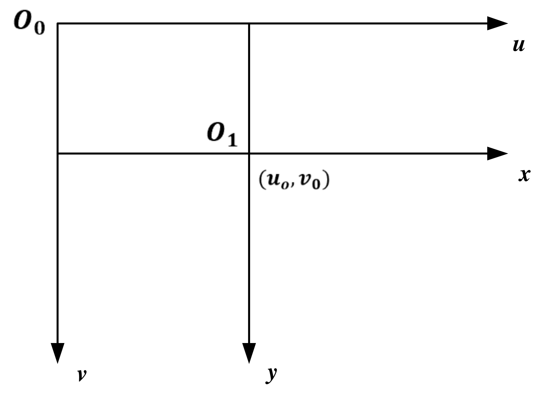
As shown in
Figure 6, to establish the transformation relationship between an image coordinate and pixel coordinate, the variational sizes in the pixel are expressed as
and
:
The expression in matrix form is:
4.4. CNN in the Damage Assessment of Post-Earthquake Buildings
The core of intelligent damage assessment based on CV and AR is to perceive information in real time and respond according to the target task [
43]. According to research and practical experience in the literature [
44,
45,
46], this paper selected the CNN as the deep learning algorithm to complete intelligent damage assessment.
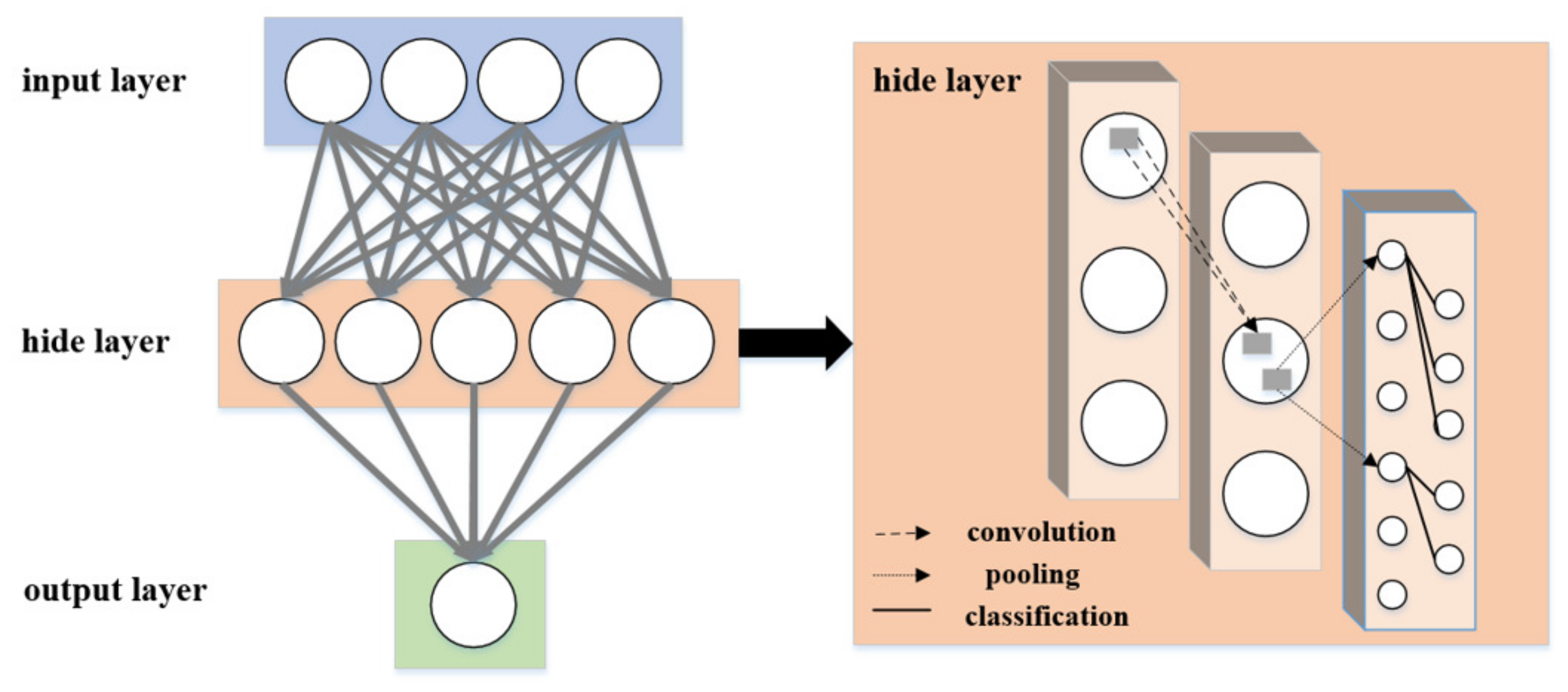
A complete CNN model consists of three layers: an input layer, a hidden layer, and an output layer (as shown in
Figure 7). The hidden layer is the core part of the CNN, which includes three common layers: convolutional layer, pooling layer, and fully connected layer. The function of the convolutional layer is to apply convolutional filters to extract features from the images. The pooling layer is divided into maximum pooling and average pooling. The purpose of the pooling layer is to compress the feature map, remove redundant information, and prevent overfitting. The fully connected layer has a mapping relationship with all the elements of the previous layer, which is represented as the probability of the final category of the input image.
The Sigmoid function, a commonly used activation function in CNNs, is often used for classification. This paper also uses the Sigmoid function as the activation function. To judge the robustness and generalization ability of the CNN model in this study, two parameters, i.e., the accuracy rate and the loss function, are introduced as evaluation indicators [
32]. The definition matrix of each evaluation indicator is shown in
Table 2, and the definition formula is as follows:
where
is the label of sample
, 1 for TP and 0 for FN and
is the probability that sample
is TP.
Even if the same buildings experienced the same earthquake, it would hardly produce the same damage [
47]. Data augmentation is the expansion of the amount of original data using image rotation, image horizontal flip, image horizontal displacement, image vertical displacement, image random cropping, and image random methods [
48]. Thus, data augmentation is necessary to ensure the learning ability and robustness of CNNs [
49].
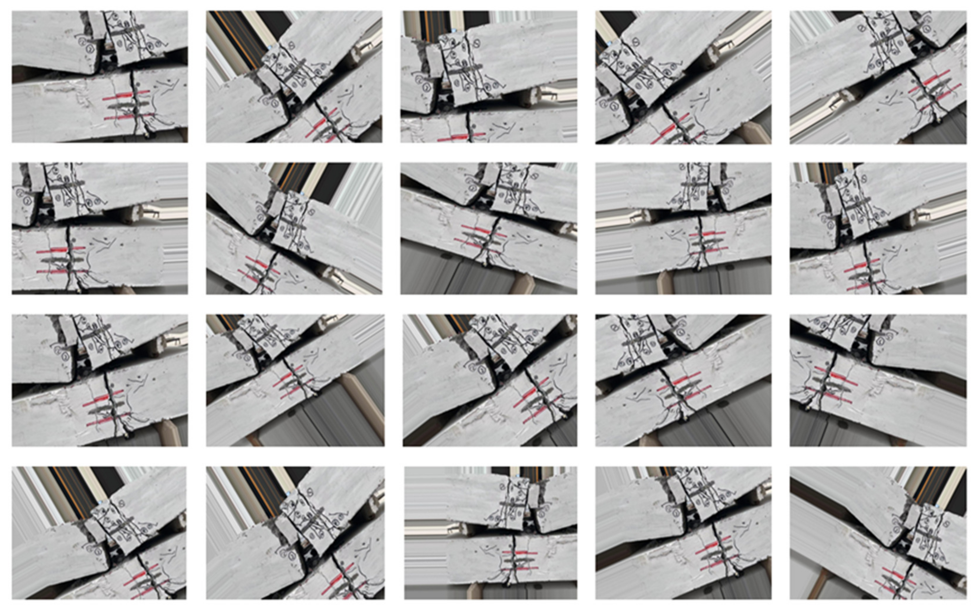
Figure 8 shows an example after data augmentation of RC beams in the ratio of 1:20 including image rotation, image horizontal flip, image horizontal displacement, image vertical displacement, image random cropping, and image random methods.
Figure 8 shows that there were more different images after data augmentation. Data augmentation can effectively expand datasets, which improves the learning ability and robustness of the CNN.
5. A Case Study on the Damage Assessment of Post-Earthquake RC Beams
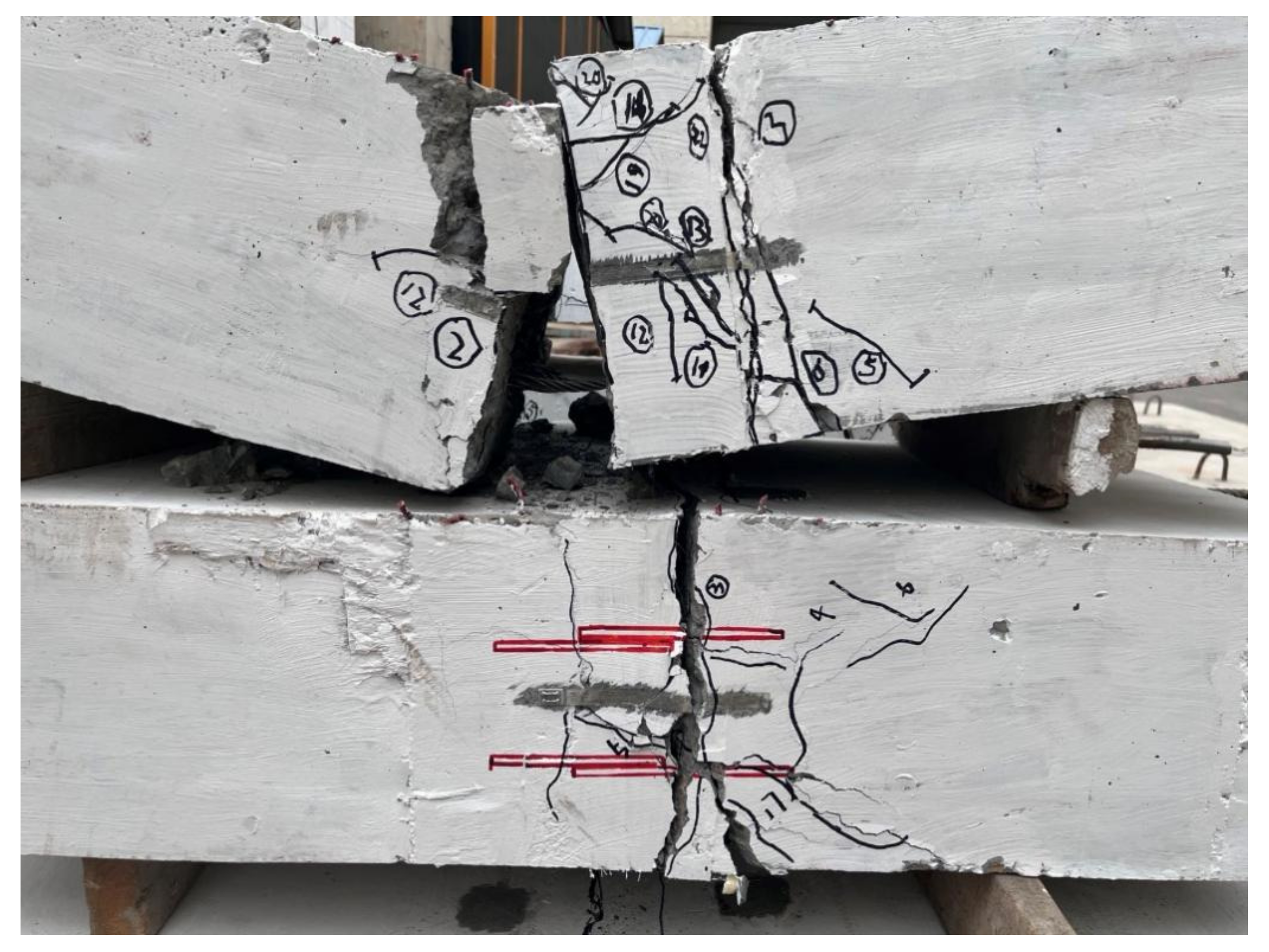
To verify the feasibility of the proposed method for intelligent damage assessment of seismic buildings, this paper used the RC beams (Simply supported beams) in an earthquake simulation laboratory as an example for a damage assessment. The decided damage assessment content is listed in
Table 1. For the seismic RC beams, the damage assessment needs information on the concrete state and crack state. The state of the crack includes information on the crack type and crack width. The seismic RC beams in the earthquake simulation laboratory are shown in
Figure 9. One of the RC beams is broken, and the other has cracks. Both beams have concrete peeling.
5.1. Crack Width Information of Post-Earthquake RC Beam Based on AR
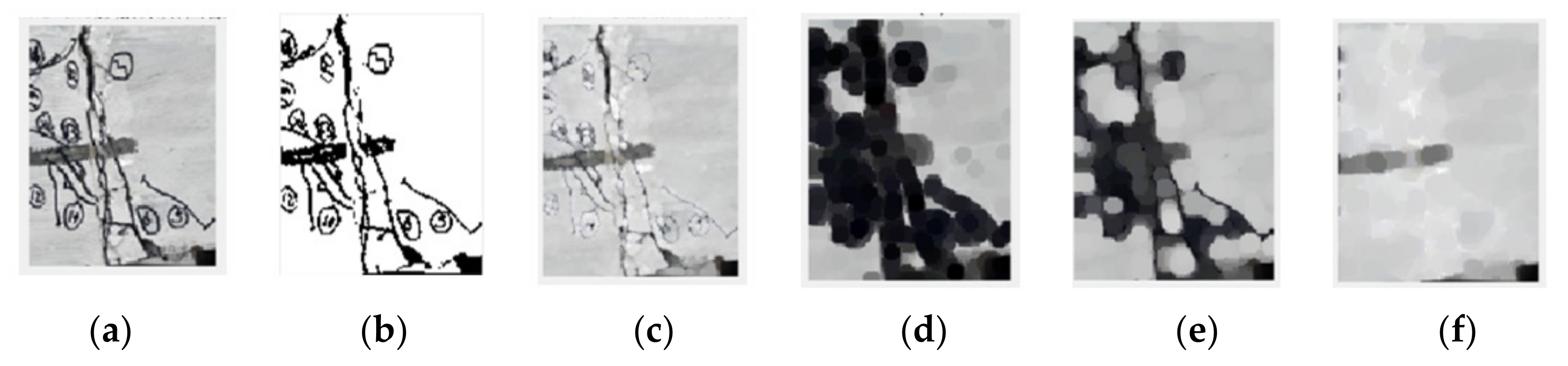
When evaluating the damage to RC beams, the crack width must be measured first. Obtaining the crack width using a gray value can reduce the deviation caused by photographing operations and algorithm processing. Especially for small cracks, a gray value provides better accuracy of the crack width. To obtain the gray value of the crack, this paper first conducted the corrosion, expansion, and opening and closing operations. The grayscale morphology of the cracks is shown in
Figure 10.
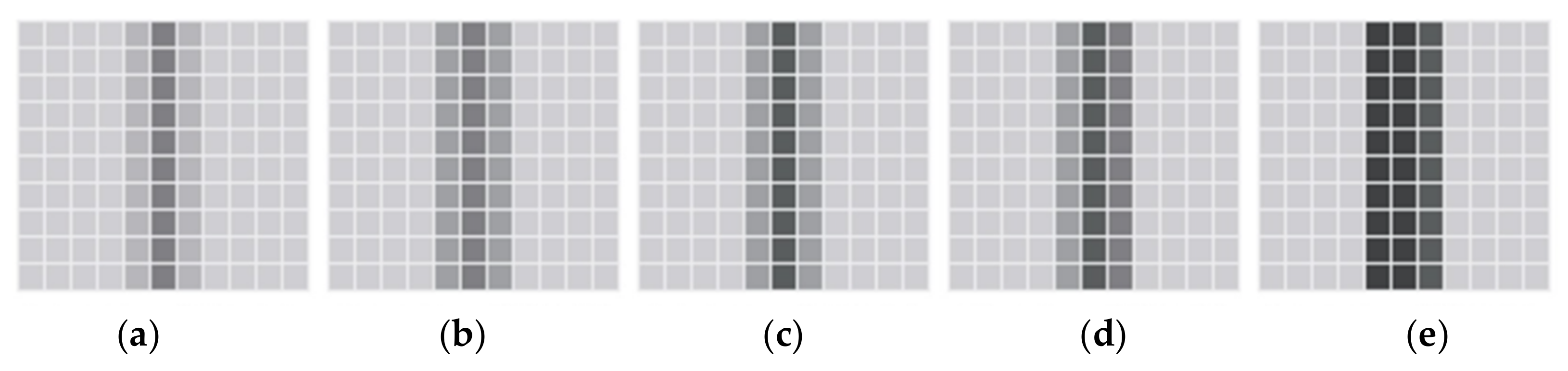
The relationship between pixel coordinates and camera space coordinates is the key to accurately calculating the crack width. According to the test data, the corresponding relationship between the average gray value and the crack width is established [
50]. When the shooting distance is 1m, the gray values corresponding to different crack widths are shown in
Figure 11.
When the corresponding relationship between the gray value and the crack width is established, the shooting distance between the image perception sensor and seismic RC beams is determined as 1m. Before information collection, the shooting distance is calculated using the measure sensors of the information collection terminal.
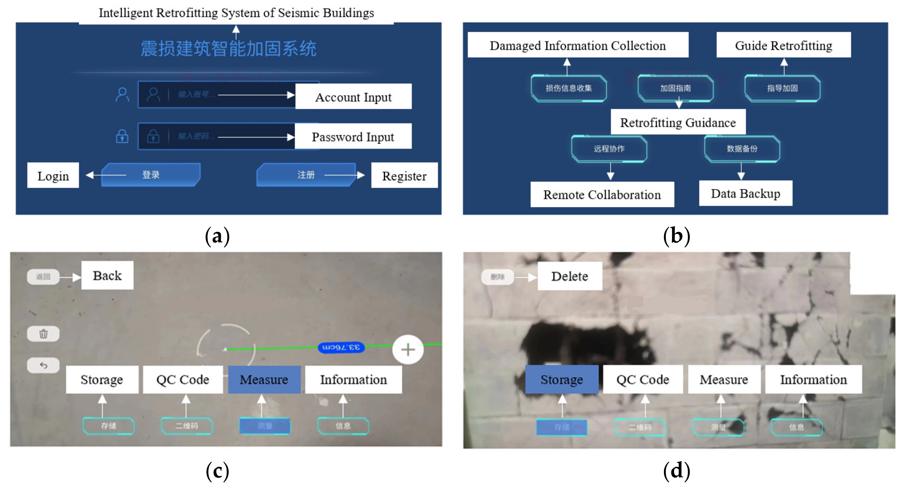
In order to verify the feasibility of the AR collection method proposed in this paper, the authors developed a simple information collection system. This information collection system can measure the shooting distance and take pictures of post-earthquake and then transform the information between the shooting distance and pictures pixels using image cognition and grey value calculation. In addition, the damage components and damage information can be visually displayed with the AR platform. The use process of the information collection system is shown in
Figure 12. Due to the still immature development of the system, the visualization of the information collection system is not of very good quality. Furthermore, as this is Chinese software and technology, only the Chinese language is supported at present.
5.2. Concrete and Crack Type Information of a Post-Earthquake RC Beam Based on a CNN
A complete CNN image recognition process includes image segmentation and data augmentation. The segmented image is called a patch. After filtering and data enhancement, a total of 4980 patches are available. 227 × 27 is the pixel size of the patches. After image segmentation, when the pixel size of the patches is 227 × 227, the damage state can be recognized well, and after reviewing the literature, our team found that a patch of this size is often used as the size for CNN recognition. If the pixel size is smaller than 227 × 227, the damage state can still be recognized well, but it will waste more manpower and time.
The authors collected 253 images with pixels 4032 × 3024 in the earthquake simulation laboratory to perform image recognition. After image augmentation, 4980 patches (227 × 227) were finally available for damage assessment [
48]. According to the different crack widths, these 4980 images were divided into three databases: 01 (ω ≤ 0.5 mm), 02 (0.5 < ω > 2 mm), and 03 (ω ≥ 2 mm). The images were used to recognize the state of concrete and cracks. The training set and test set were classified according to the ratio of 2:1. The statistical information about the dataset is shown in
Table 3.
The CNN model in this paper was set to three convolutional blocks and one fully connected block, as shown in
Figure 13. Each convolutional block contained two convolutional layers and a pooling layer, and the image after one feature extraction was used as input to the next convolution block. After three feature extractions were completed, the task of damage classification was completed in the fully connected layer. Softmax is a classifier. Using probability assignment, Softmax can classify different images into different sets.
In convolution block 1, 32@3 × 3 filters were used to extract features from the input image. In convolution block 2, each convolution layer used 64@3 × 3 filters. In convolution block 3, each convolution layer used 128@3 × 3 filters. The pooling layer was max pooling, the size of the pooling layer was 2 × 2, and the step size was 2. After the input passed through the fully connected layer, the images were changed from a three-dimensional matrix to a one-dimensional vector. One-dimensional vectors were classified with activation functions. The specific parameters of the CNN model are shown in
Table 4, and the illustration of the CNN model is shown in
Figure 13.
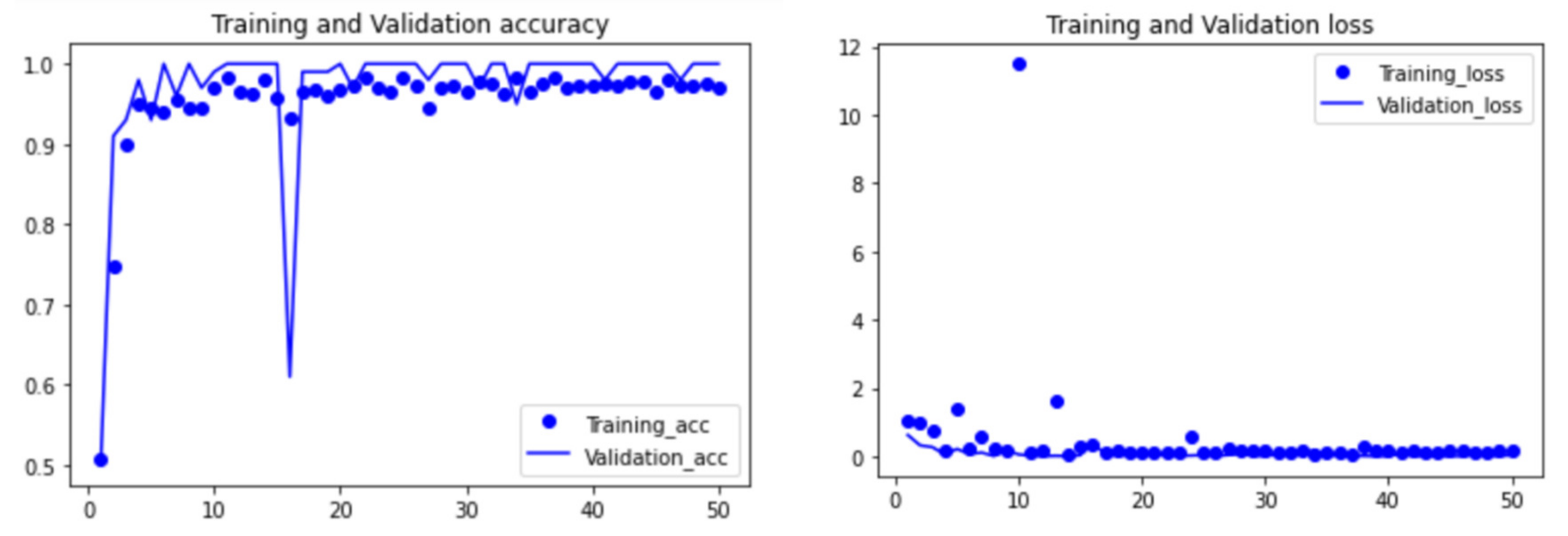
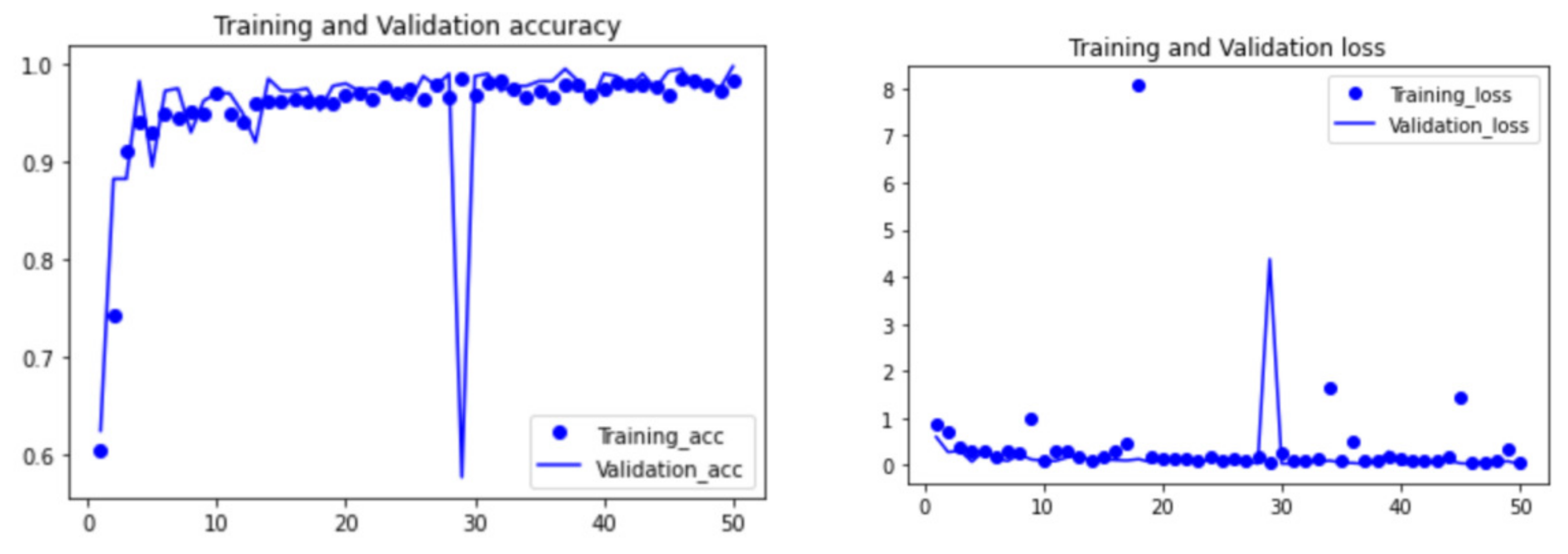
The process of image recognition mainly includes “model definition”, “data preprocessing (data augmentation)”, and “result visualization”. All the steps are implemented using python. The processed images were input into the CNN model, and the batch size of both the training set and validation set was 16. The number of iterations of the training set (echo) was 50. The visual results of the recognition accuracy and loss function generated in these 50 cycles are shown in
Figure 14 and
Figure 15.
It can be seen from the above figures that in the first 20 cycles, the accuracy and loss function values of the CNN model were not stable enough. In addition, there was still space for improvement in the accuracy and loss. However, with the number of cycles increasing, the accuracy and loss function tended to be stable and reach an ideal state. After 50 cycles, the accuracy of the CNN model training set increased from about 50% to 99.75%, and the validation set accuracy reached 98.25%. The loss function of the training set was 0.0258, and the loss function of the validation set was 0.0252.
5.3. Visual Display of the Damage Assessment Using AR
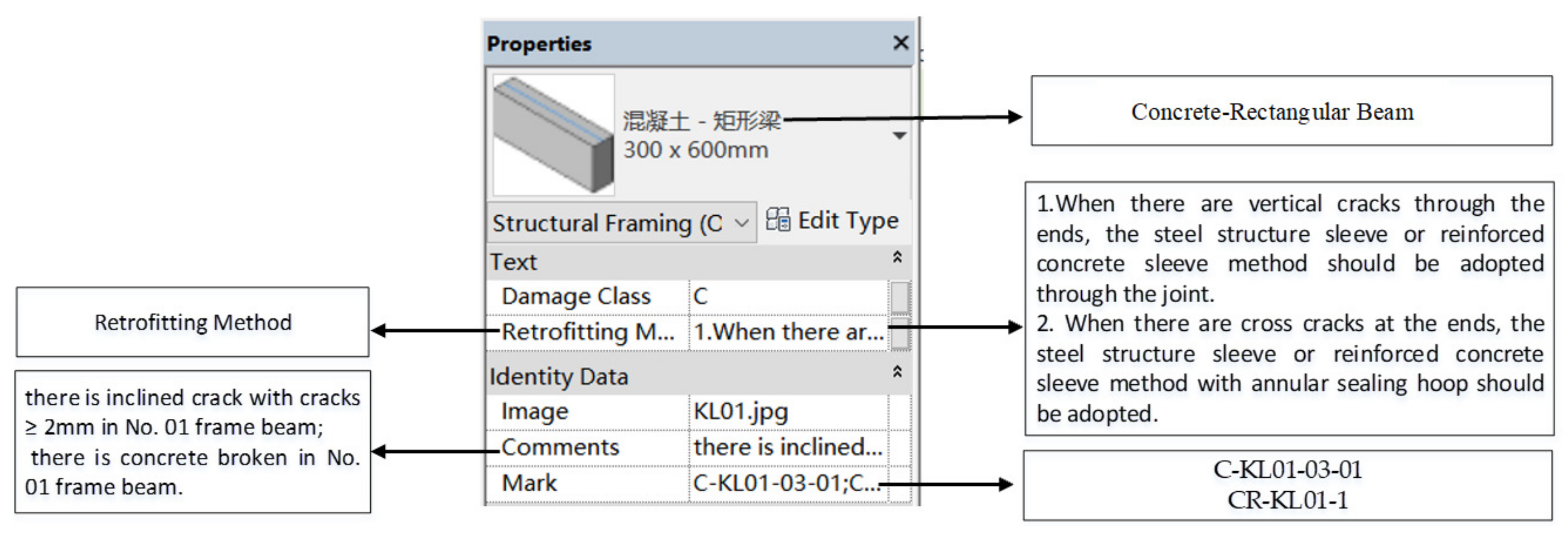
The information on shooting distance and images of the damaged RC beams collected using the above system would be transferred to a computer terminal. For the visual display method of damage components and damage information, our team has already carried out many studies, and this paper applied the method of BIM-AR to display the damage model and damage information. The visual damage components and damage information are displayed with a computer, as shown in
Figure 16. All the damage information including assessment results, damage models, and retrofitting methods were visually displayed using the AR platform (Augin
®), as shown in
Figure 17. The expression of the damage assessment comes from the specification ’Building Structural Drawing Standards’ [
51]. The expression of the damage information comes from a set of coding rules [
16].
When C-KL01-03-01: there is an inclined crack with cracks ≥ 2 mm in the no. 01 frame beam.
Where “C” represents crack; “KL01” represents the no. 01 frame beam; “03” represents the width of ≥2 mm; and “01” represents the type of the crack as an inclined crack.
When CR-KL01-1: there is broken concrete in the no. 01 frame beam.
Where “CR” represents concrete broken; “KL01” represents the no. 01 frame beam; and “1” represents a true positive.
After assessment of the crack width, crack type, and concrete fracture condition of RC beams, the results showed that the damage class of the component was C.
6. Conclusions
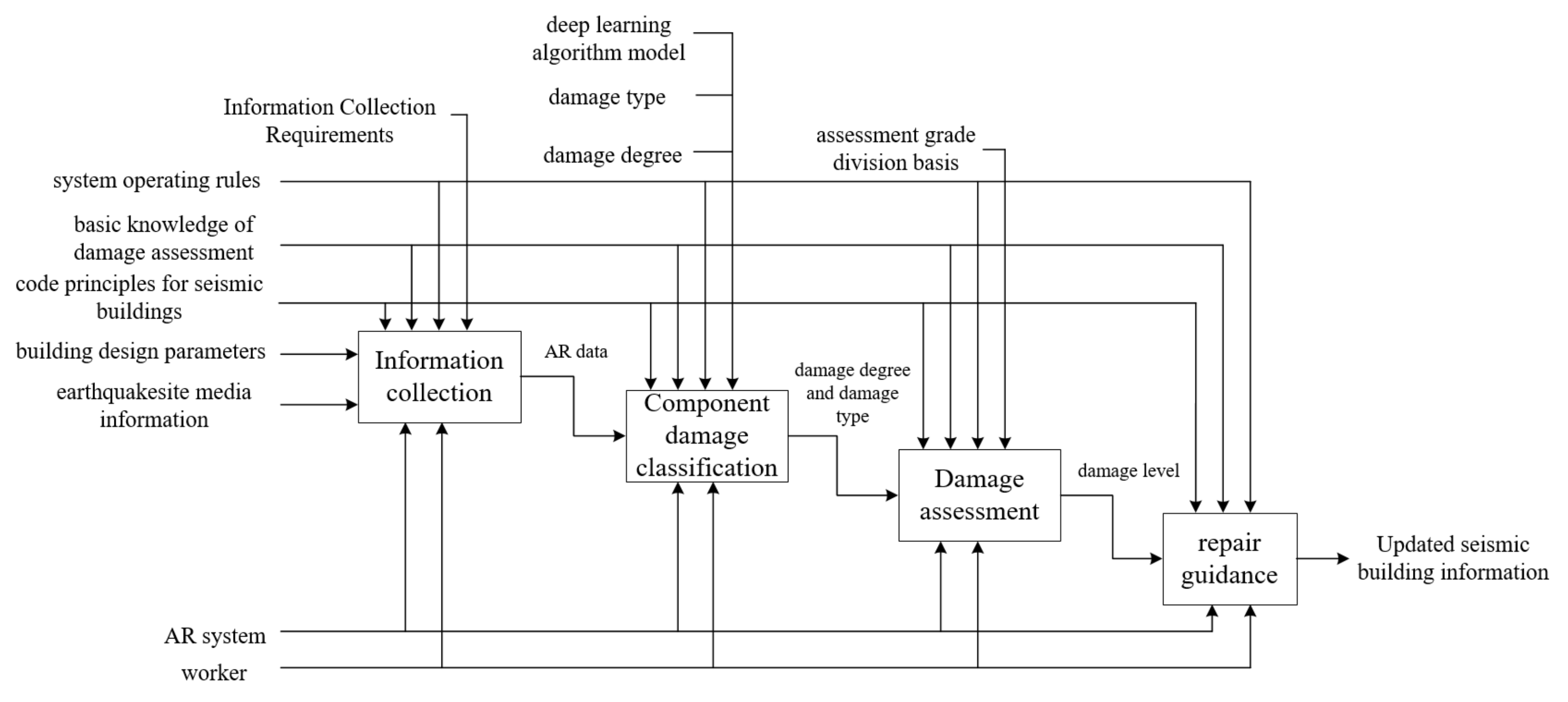
The rapid development of CV and AR has provided more scientific, effective, and visual ideas for the damage assessment of post-earthquake buildings. The IDEFO (Icam Definition Method) of the intelligent assessment method is shown in
Figure 18.
CV is the key technology to realize the traditional upgrade in the damage assessment for seismic buildings. AR is an indispensable technology for further improving the scientific, visualization, and information management of damage assessments. This paper proposed a damage assessment method for post-earthquake buildings combining CV and AR. The proposed method can improve the problems in visual inspection, such as high subjectivity, redundant data in the damage assessment process, and difficulty in information management and retrieval. The conclusions of this paper are drawn below:
This paper provided information on the fusion mechanism of CV and AR. The fusion of CV and AR not only enriches the diversity of post-earthquake building information but also realizes a closed loop of information generated during the assessment process.
This paper applied the registration technology to obtain AR data and established the transformation relationship between virtual world coordinates, real-world coordinates, and camera world coordinates. It is worth noting that the virtual–real fusion information provides a better data basis for damage assessment.
The aim of the damage assessment method for earthquake-damaged buildings is to classify different damage states into different classes. CNNs and grey values are used to analyze and process the original data. The CNN is used for image recognition, and the grey value is used to calculate the quantitative information. CNNs and grey values can not only ensure the accuracy of classification but can also prevent the problem of overfitting.
The proposed damage assessment method combining CV and AR can evaluate the damage class of seismic components more intelligently. This method not only improves the scientific accuracy and visualization of a damage assessment but also effectively solves the problems of data redundancy, information management, and retrieval difficulties. However, there are still some deficiencies. In this paper, information collection with AR and information display with AR used different AR terminals, which is not conducive to real-time analysis and information integration. Although the information on image recognition and gray value calculation can be updated in real-time, the information on the visual display terminal still needs the help of workers.
Finally, the current research on the damage assessment of post-earthquake buildings is still insufficient. Further improvement in the science of damage assessment and data management remains a priority for future research. Next, our team will work to integrate damage assessment and damage information visualization. In the future, we will continue to dynamically link and visualize damage assessment information with building design information and reinforcement method information. Then, we will try to promote the intelligence, digitization, and visualization of repair and retrofitting methods of post-earthquake buildings.
7. Patents
Based on the content of this study, an invention patent has been applied.
Author Contributions
Conceptualization, Z.L.; methodology, Z.L.; software, Z.L.; validation, Z.L., J.X. and W.B.; writing—original draft preparation, J.X.; writing—review and editing, N.W. and Y.M.; project administration, Z.L.; funding acquisition, Z.L. All authors have read and agreed to the published version of the manuscript.
Funding
This research was funded by the National Key R&D Program of China, grant number 2019YFC1509304-06.
Institutional Review Board Statement
Not applicable.
Informed Consent Statement
Not applicable.
Data Availability Statement
Data sharing is not applicable.
Acknowledgments
The authors would like to thank the Laboratory of Beijing University of Technology for all seismic test block models.
Conflicts of Interest
The authors declare no conflict of interest.
Abbreviations
| CV | Computer Vision | AR | Augmented Reality |
| CNN | Convolutional Neural Network | UAV | Unmanned Aerial Vehicle |
| FEMA | Federal Management Emergency Administration | SVM | Support Vector Machine |
| BIM | Building Information Model | R-CNN | Region-Convolutional Neural Network |
| RC | Reinforced Concrete Frame | IDEFO | Icam Definition Method |
References
- Dong, L.; Shan, J. A comprehensive review of earthquake-induced building damage detection with remote sensing techniques. J. Photogramm. Remote Sens. 2013, 84, 85–99. [Google Scholar] [CrossRef]
- Zhou, Z.; Goh, Y.M.; Li, Q. Overview and analysis of safety management studies in the construction industry. Saf. Sci. 2015, 72, 337–350. [Google Scholar] [CrossRef]
- Porter, K.; Hellman, S.; Hortacsu, A. FEMA ROVER Version 2 and ROVER ATC-20, Mobile Earthquake Safety Software. In Improving the Seismic Performance of Existing Buildings and Other Structures; ASCE: San Francisco, CA, USA, 2015. [Google Scholar]
- Zhang, L.; Pan, Y. Information fusion for automated post-disaster building damage evaluation using deep neural network. Sustain. Cities Soc. 2022, 77, 103574. [Google Scholar] [CrossRef]
- Cui, C.; Xu, M.; Xu, C.; Zhang, P.; Zhao, J. An ontology-based probabilistic framework for comprehensive seismic risk evaluation of subway stations by combining Monte Carlo simulation. Tunn. Undergr. Space Technol. 2023, 135, 105055. [Google Scholar] [CrossRef]
- Cui, C.; Liang, Z.; Xu, C.; Xin, Y.; Wang, B. Analytical solution for horizontal vibration of end-bearing single pile in radially heterogeneous saturated soil. Appl. Math. Model. 2023, 116, 65–83. [Google Scholar] [CrossRef]
- Meng, K.; Cui, C.; Liang, Z.; Li, H.; Pei, H. A new approach for longitudinal vibration of a large-diameter floating pipe pile in visco-elastic soil considering the three-dimensional wave effects. Comput. Geotech. 2020, 128, 103840. [Google Scholar] [CrossRef]
- Cui, C.; Meng, K.; Xu, C.; Wang, B.; Xin, Y. Vertical vibration of a floating pile considering the incomplete bonding effect of the pile-soil interface. Comput. Geotech. 2022, 150, 104894. [Google Scholar] [CrossRef]
- Polimeno, M.R.; Roselli, I.; Luprano, V.; Mongelli, M.; Tatì, A.; De Canio, G. A non-destructive testing methodology for damage assessment of reinforced concrete buildings after seismic events. Eng. Struct. 2018, 163, 122–136. [Google Scholar] [CrossRef]
- Cui, C.; Meng, K.; Xu, C.; Liang, Z.; Li, H.; Pei, H. Analytical solution for longitudinal vibration of a floating pile in saturated porous media based on a fictitious saturated soil pile model. Comput. Geotech. 2021, 131, 103942. [Google Scholar] [CrossRef]
- Cabanas, L.; Benito, B.; Herraiz, M. An approach to the measurement of the potential structural damage of earthquake ground motions. Earthq. Eng. Struct. Dyn. 1998, 1, 79–92. [Google Scholar] [CrossRef]
- Van de Lindt, J.W.; Goh, G.H. Effect of earthquake duration on structural reliability. Eng. Struct. 2004, 26, 1585–1597. [Google Scholar] [CrossRef]
- Song, R.; Li, Y.; van de Lindt, J.W. Impact of earthquake ground motion characteristics on collapse risk of post-mainshock buildings considering aftershocks. Eng. Struct. 2014, 81, 349–361. [Google Scholar] [CrossRef]
- Gaxiola-Camacho, J.R.; Azizsoltani, H.; Villegas-Mercado, F.J.; Haldar, A. A novel reliability technique for implementation of Performance-Based Seismic Design of structures. Eng. Struct. 2017, 142, 137–147. [Google Scholar] [CrossRef] [Green Version]
- De Risi, R.; Goda, K.; Tesfamariam, S. Multi-dimensional damage measure for seismic reliability analysis. Structural Safety. 2019, 18, 1–11. [Google Scholar] [CrossRef]
- Liu, Z.; Bai, W. Building Information Modeling Methods for Post-Earthquake Retrofitting Visualization of Buildings Using Augmented Reality. Appl. Sci. 2021, 11, 5739. [Google Scholar] [CrossRef]
- Ali, R.; Kang, D.; Suh, G.; Cha, Y.-J. Real-time multiple damage mapping using autonomous UAV and deep faster region-based neural networks for GPS-denied structures. Autom. Constr. 2021, 130, 103831. [Google Scholar] [CrossRef]
- Zhu, Z.; German, S.; Roberts, S.; Brilakis, I.; Des Roches, R. Machine Vision Enhanced Post-Earthquake Inspection. Comput. Civ. Eng. 2011, 152–160. [Google Scholar] [CrossRef]
- Federal Emergency Management Agency (F.E.M.A. USA). Rapid Visual Screening of Buildings for Potential Seismic Hazards: A Handbook (Fema P-154); Applied Technological Council (ATC): Redwood City, CA, USA, 2011.
- Levine, N.M.; Spencer, B.F., Jr. Post-Earthquake Building Evaluation Using UAVs: A BIM-Based Digital Twin Framework. Sensors 2022, 22, 873. [Google Scholar] [CrossRef]
- Mongelli, M.; De Canio, G.; Roselli, I.; Malena, M.; Nacuzi, A.; de Felice, G. 3D Photogrammetric reconstruction by drone scanning for FE analysis and crack pattern mapping of the “Bridge of the Towers”, Spoleto. Key Eng. Mater. 2017, 747, 423–430. [Google Scholar] [CrossRef]
- Wang, W.; Wang, M.; Li, H.; Zhao, H.; Wang, K.; He, C.; Wang, J.; Zheng, S.; Chen, J. Pavement crack image acquisition methods and crack extraction algorithms: A review Journal of Traffic and Transportation Engineering. Period. Off. Chang. Univ. 2019, 6, 535–556. [Google Scholar] [CrossRef]
- Shakya, M.; Kawan, C.K.; Gaire, A.K.; Duwal, S. Post-earthquake damage assessment of traditional masonry buildings: A case study of Bhaktapur municipality following 2015 Gorkha (Nepal) earthquake. Eng. Fail. Anal. 2021, 123, 105277. [Google Scholar] [CrossRef]
- Koch, C.; Georgieva, K.; Kasireddy, V.; Akinci, B.; Fieguth, P. A review on computer vision based defect detection and condition assessment of concrete and asphalt civil infrastructure. Adv. Eng. Inform. 2015, 29, 196–210. [Google Scholar] [CrossRef] [Green Version]
- Varun Kumar Reja, Koshy Varghese, Quang Phuc Ha, Computer vision-based construction progress monitoring. Autom. Constr. 2022, 138, 104245. [CrossRef]
- Fayed, H.A.; Atiya, A.F. Decision boundary clustering for efficient local SVM. Appl. Soft Comput. 2021, 110, 107628. [Google Scholar] [CrossRef]
- Shanmugam, P.; Raja, J.; Pitchai, R. An automatic recognition of glaucoma in fundus images using deep learning and random forest classifier. Appl. Soft Comput. 2021, 109, 107512. [Google Scholar] [CrossRef]
- Mostafa, K.; Hegazy, T. Review of image-based analysis and applications in construction. Autom. Constr. 2021, 122, 103516. [Google Scholar] [CrossRef]
- Guo, J.; Wang, Q.; Li, Y.; Liu, P. Façade defects classification from imbalanced dataset using meta learning-based convolutional neural network. Comput-Aided Civ. Infrastruct. Eng. 2020, 35, 1403–1418. [Google Scholar] [CrossRef]
- Perez, H.; Tah, J.H.; Mosavi, A. Deep learning for detecting building defects using convolutional neural networks. Sensors 2019, 19, 3556. [Google Scholar] [CrossRef] [Green Version]
- Cha, Y.-J.; Choi, W.; Büyüköztürk, O. Deep learning-based crack damage detection using convolutional neural networks. Comput. -Aided Civ. Infrastruct. Eng. 2017, 32, 361–378. [Google Scholar] [CrossRef]
- Botta, B.; Gattam, S.S.R.; Datta, A.K. Eggshell crack detection using deep convolutional neural networks. J. Food Eng. 2022, 315, 110798. [Google Scholar] [CrossRef]
- Bai, T.; Yang, J.; Xu, G.; Yao, D. An optimized railway fastener detection method based on modified Faster R-CNN. Measurement 2021, 182, 109742. [Google Scholar] [CrossRef]
- Zheng, M.; Xue, Q.; Wei, W.; Xu, Z. A Review on the Research Using Building Information Model Technology in Multi-Hazards Topic. J. Graph. 2018, 39, 829–834. [Google Scholar] [CrossRef]
- Borsci, S.; Lawson, G.; Broome, S. Empirical evidence, evaluation criteria and challenges for the effectiveness of virtual and mixed reality tools for training operators of car service maintenance. Comput. Ind. 2015, 67, 17–26. [Google Scholar] [CrossRef]
- Delgado, J.M.D.; Oyedele, L.; Demian, P.; Beach, T. A research agenda for augmented and virtual reality in architecture, engineering and construction. Adv. Eng. Inform. 2020, 45, 101122. [Google Scholar] [CrossRef]
- Garbett, J.; Hartley, T.; Heesom, D. A multi-user collaborative BIM-AR system to support design and construction. Autom. Constr. 2021, 122, 103487. [Google Scholar] [CrossRef]
- Yang, S.; Wu, J.; Dai, G.; Xin, H.; Fan, Y.; Wong, D.; Miao, Q.; Dai, J.; Hu, K.; Yi, F.; et al. Technical Specification for Post-earthquake Urgent Assessment and Repair of Buildings; China Architecture & Building Press: Beijing, China, 2017; pp. 27–36. [Google Scholar]
- Liu, Y.; Fan, J.; Nie, J.; Kong, S.; Qi, Y. Review and prospect of digital-image-based crack detection of structure surface. Civ. Eng. J. 2021, 54, 79–98. (In Chinese) [Google Scholar] [CrossRef]
- Brown, M.; Windridge, D.; Guillemaut, J.-Y. A family of globally optimal branch-and-bound algorithms for2D–3D correspondence-free registration. Pattern Recognit. 2019, 93, 36–54. [Google Scholar] [CrossRef]
- Jin, J.; Chen, Y. Three. Three dimensional registration techniques for augmented reality based on computer vision and magnetic tracking. Comput. Appl. 2006, 6, 1485–1489. (In Chinese) [Google Scholar]
- Shi, X.; Bian, N. Research and Implementation of Cellphone-Based Augmented Reality Indoor Guide. Comupter Appl. Softw. 2013, 30, 320–323. (In Chinese) [Google Scholar]
- Bouguettaya, A.; Zarzour, H.; Taberkit, A.M.; Kechida, A. A review on early wildfire detection from unmanned aerial vehicles using deep learning-based computer vision algorithms. Signal Process. 2022, 190, 108309. [Google Scholar] [CrossRef]
- Xu, J.; Zhou, S.; Xu, A.; Ye, J.; Zhao, A. Automatic scoring of postures in grouped pigs using depth image and CNN-SVM. Comput. Electron. Agric. 2022, 194, 106746. [Google Scholar] [CrossRef]
- Koklu, M.; Unlersen, M.F.; Ozkan, I.A.; Aslan, M.F.; Sabanci, K. A CNN-SVM study based on selected deep features for grapevine leaves classification. Measurement 2022, 188, 110425. [Google Scholar] [CrossRef]
- De, A.; Chowdhury, A.S. DTI based Alzheimer’s disease classification with rank modulated fusion of CNNs and random forest. Expert Syst. Appl. 2021, 169, 114338. [Google Scholar] [CrossRef]
- Alvanitopoulos, P.; Andreadis, I.; Elenas, A. Neuro-fuzzy techniques for the classification of earthquake damages in buildings. Measurement 2010, 43, 797–809. [Google Scholar] [CrossRef]
- Chen, K.; Reichard, G.; Xu, X.; Akanmu, A. Automated crack segmentation in close-range building façade inspection images using deep learning techniques. J. Build. Eng. 2021, 43, 102913. [Google Scholar] [CrossRef]
- Ge, Y.; Liu, H.; Wang, Y.; Xu, B.; Zhou, Q.; Shen, F. Survey on Deep Learning Image Recognition in Dilemma of Small Samples. J. Softw. 2022, 33, 193–210. (In Chinese) [Google Scholar]
- Yang, S.; Chen, H.; Li, X. Research on determining crack width by image gray scal. J. Highw. Transp. Res. Dev. 2018, 14, 71–72. (In Chinese) [Google Scholar]
- GB/T 50105-2010; Standard For Structural Drawings. China Architecture & Building Press: Beijing, China, 2010.
Figure 1.
The assessment process combines CV and AR.
Figure 1.
The assessment process combines CV and AR.
Figure 2.
The fusion mechanism of CV and AR in the damage assessment system. The Chinese characters in the picture on the bottom right means Concrete-Rectangular Beam.
Figure 2.
The fusion mechanism of CV and AR in the damage assessment system. The Chinese characters in the picture on the bottom right means Concrete-Rectangular Beam.
Figure 3.
The damage assessment process for RC beams.
Figure 3.
The damage assessment process for RC beams.
Figure 4.
The transformation relationship of coordinates.
Figure 4.
The transformation relationship of coordinates.
Figure 5.
The transformation of camera coordinates to image coordinates.
Figure 5.
The transformation of camera coordinates to image coordinates.
Figure 6.
The transformation relationship between an image coordinate and a pixel coordinate.
Figure 6.
The transformation relationship between an image coordinate and a pixel coordinate.
Figure 7.
The complete architecture of a CNN.
Figure 7.
The complete architecture of a CNN.
Figure 8.
An example of data augmentation for an image of RC beams in the ratio of 1:20.
Figure 8.
An example of data augmentation for an image of RC beams in the ratio of 1:20.
Figure 9.
The seismic RC beams in the earthquake simulation laboratory.
Figure 9.
The seismic RC beams in the earthquake simulation laboratory.
Figure 10.
The gray scale morphology of the cracks. (a) Image, (b) binarization, (c) corrosion, (d) expansion, (e) opening, and (f) closing.
Figure 10.
The gray scale morphology of the cracks. (a) Image, (b) binarization, (c) corrosion, (d) expansion, (e) opening, and (f) closing.
Figure 11.
The different gray values of different crack widths [
50]. (
a) Width: 0.09 mm, (
b) width: 0.15 mm, (
c) width: 0.20 mm, (
d) width: 0.50 mm, and (
e) width: 1.00 mm.
Figure 11.
The different gray values of different crack widths [
50]. (
a) Width: 0.09 mm, (
b) width: 0.15 mm, (
c) width: 0.20 mm, (
d) width: 0.50 mm, and (
e) width: 1.00 mm.
Figure 12.
The steps in the use process of the information collection terminal. (a) System login, (b) function selection, (c) measure shooting distance, and (d) take the image.
Figure 12.
The steps in the use process of the information collection terminal. (a) System login, (b) function selection, (c) measure shooting distance, and (d) take the image.
Figure 13.
The illustration of the CNN model.
Figure 13.
The illustration of the CNN model.
Figure 14.
Experimental results of the CNN model on the damage type of crack.
Figure 14.
Experimental results of the CNN model on the damage type of crack.
Figure 15.
Experimental results of the CNN model on the damage type of concrete.
Figure 15.
Experimental results of the CNN model on the damage type of concrete.
Figure 16.
The damage information displayed in the terminal.
Figure 16.
The damage information displayed in the terminal.
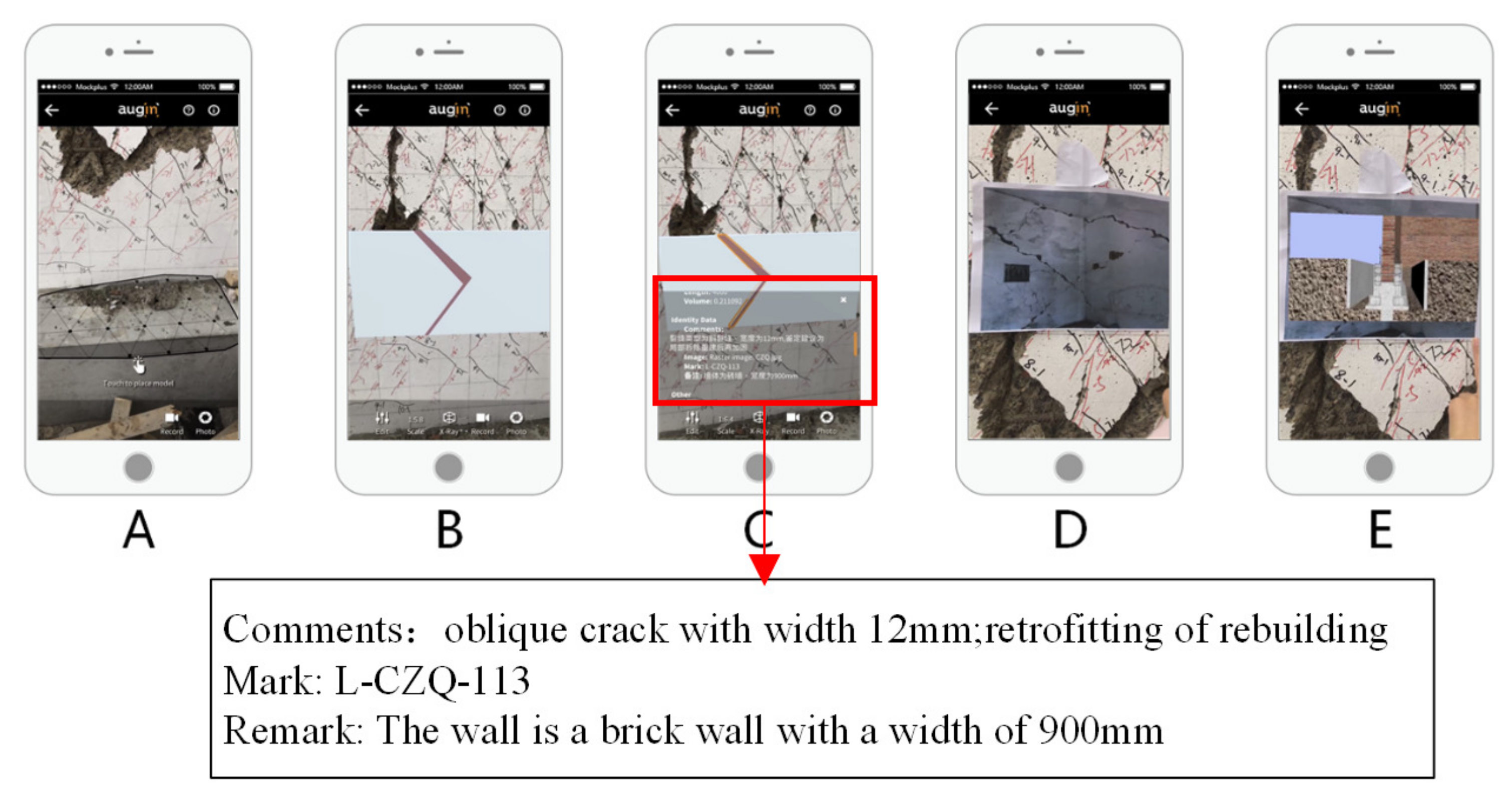
Figure 17.
Steps to viewing the damage model and information: (
A) place the model, (
B) view the model, (
C) view detailed information on the damage, (
D) identify the thumbnail, and (
E) display the repair video [
24].
Figure 17.
Steps to viewing the damage model and information: (
A) place the model, (
B) view the model, (
C) view detailed information on the damage, (
D) identify the thumbnail, and (
E) display the repair video [
24].
Figure 18.
The IDEFO of the damage assessment method.
Figure 18.
The IDEFO of the damage assessment method.
Table 1.
The Description of Damage Classes for Reinforced Concrete Frame Beams.
Table 1.
The Description of Damage Classes for Reinforced Concrete Frame Beams.
| Concrete State | Crack State | Crack Width | Damaged Class | Retrofitting Method |
|---|
| Unbroken | none | / | Class A | / |
| only diagonal crack or cross crack | <0.5 mm | Class B | ω < 0.3: When the crack is shallow, epoxy resin slurry or cement slurry should be used for surface sealing; when the crack is deep, acrylic slurry or low viscosity epoxy resin slurry should be used for pressure grouting repair. 0.3 ≤ ω < 2.0: The crack should be repaired with epoxy resin grout pressure grouting. 2.0 ≤ ω < 5.0: The crack can be repaired using pressure grouting with materials such as micro-expansion cement grouting. When the components are seriously cracked and the concrete is slightly dropped, the replacement method should be used to re-pour the components, and then steel structure sleeves or reinforced concrete sleeves should be used for reinforcement.
|
| only non-penetrating crack at the end of a beam | <2 mm |
| only diagonal crack or cross crack | ≥0.5 mm | Class C | When there are vertical cracks through the ends, the steel structure sleeve or reinforced concrete sleeve method should be used through the joint. When there are cross cracks at the ends, the steel structure sleeve or reinforced concrete sleeve method with annular sealing hoop should be used.
|
| only non-penetrating crack at the end of beam | ≥2 mm |
| Broken | / | / | Class C | / |
Table 2.
The definition matrix of each evaluation index.
Table 2.
The definition matrix of each evaluation index.
| | Validation |
|---|
| Damage | Background Noise |
|---|
| Training | | True Positive (TP) | False Negative (FN) |
| Background Noise | False Positive (FP) | True Negative (TN) |
Table 3.
Classification of images collected in the laboratory experiment.
Table 3.
Classification of images collected in the laboratory experiment.
| Concrete State Classes | Initial
Images | Processed
Patches | Training Patches | Test Patches |
|---|
| concrete unbroken, non-crack | 38 | 1020 | 680 | 340 |
| concrete unbroken, cross crack | 82 | 1500 | 1000 | 500 |
| concrete unbroken, horizontal, vertical crack | 93 | 1710 | 1140 | 570 |
| concrete broken | 40 | 750 | 500 | 250 |
| total | 253 | 4980 | 3320 | 1660 |
Table 4.
The specific parameters of the CNN model.
Table 4.
The specific parameters of the CNN model.
| Layer | Size of Filters | Number of Filters | Output | Number of Features |
|---|
| convolutional layer 1.1 | 3 × 3 | 32 | 225 × 225 × 32 | 320 |
| convolutional layer 1.2 | 3 × 3 | 32 | 223 × 223 × 32 | 320 |
| pooling layer 1 | 2 × 2 | - | 112 × 112 × 32 | - |
| convolutional layer 2.1 | 3 × 3 | 64 | 110 × 110 × 64 | 19,072 |
| convolutional layer 2.2 | 3 × 3 | 64 | 108 × 108 × 64 | 19,072 |
| pooling layer 2 | 2 × 2 | - | 54 × 54 × 64 | - |
| convolutional layer 3.1 | 3 × 3 | 128 | 52 × 52 × 128 | 73,856 |
| convolutional layer 3.2 | 3 × 3 | 128 | 50 × 50 × 128 | 73,856 |
| pooling layer 3 | 2 × 2 | - | 25 × 25 × 128 | - |
| fully connected layer | - | - | 80,000 | - |
| Disclaimer/Publisher’s Note: The statements, opinions and data contained in all publications are solely those of the individual author(s) and contributor(s) and not of MDPI and/or the editor(s). MDPI and/or the editor(s) disclaim responsibility for any injury to people or property resulting from any ideas, methods, instructions or products referred to in the content. |
© 2023 by the authors. Licensee MDPI, Basel, Switzerland. This article is an open access article distributed under the terms and conditions of the Creative Commons Attribution (CC BY) license (https://creativecommons.org/licenses/by/4.0/).


