Article

Finite Element Analysis for the Mechanism of Stress Wave Propagation and Crack Extension Due to Blasting of a Frozen Rock Mass

1
Hongda Blasting Engineering Group Co., Ltd., Guangzhou 510623, China
2
School of Resources and Civil Engineering, Northeastern University, Shenyang 110819, China
3
State Key Laboratory of Coastal and Offshore Engineering, Dalian University of Technology, Dalian 116024, China
4
State Key Laboratory of Frozen Soil Engineering, Northwest Institute of Eco-Environment and Resources, Chinese Academy of Sciences, Lanzhou 730000, China
*
Author to whom correspondence should be addressed.
Sustainability 2023, 15(5), 4616; https://doi.org/10.3390/su15054616
Submission received: 17 January 2023 / Revised: 13 February 2023 / Accepted: 1 March 2023 / Published: 4 March 2023
(This article belongs to the Special Issue Advances in Rock Mechanics and Geotechnical Engineering)

Abstract

:
The propagation mechanism of explosion stress waves in frozen rock mass is the main factor affecting the blasting efficiency and safety construction of strip mines in alpine cold regions. In order to study explosion stress wave propagation and crack extension in the blasting process of frozen rock mass with ice-filled cracks, RFPA2D is adopted to simulate the influence of the geometric parameters of ice-filled cracks (ice-filled crack thickness d, normal distance R from blasting hole to the ice-filled crack, and ice-filled crack angle α), loading intensity and loading rate on the explosion stress wave propagation effect and the damage range. The results show: The attenuation trend of explosion stress waves decreases gradually with an increase of thickness (e.g., In the case of R is 0.2 m, when d is 0.02 m, 0.04 m, and 0.08 m, the calculated attenuation factor of the minimum principal stress peak value is 7.128%, 18.056%, and 30.035%, respectively), and it decreases slightly with an increase of normal distance and ice-filled crack angle. The damage elements range of the ice-filled crack decreases when the ice-filled crack thickness and normal distance increases. The loading intensity and the loading rate have a significant influence on blasting hole fracture patterns. The ice-filled crack has a guiding effect on the growth of blasting cracks at the blasting hole. Nevertheless, the existence of ice-filled cracks inhibits the propagation of explosion stress waves in frozen rock mass.

1. Introduction

The design and disaster prevention of open pit blasting mining of mineral resources in cold regions have become key issues in the field of energy safety mining. There are a large number of naturally formed intermittent joint cracks, bedding and faults in rock mass. The existence of these structural planes affects the mechanical properties, vibration, permeability, energy transfer and other properties of rock mass. Affected by low temperature, the water in the primary fissures of open pit slopes becomes ice, which forms frozen rock mass [1,2,3,4]. The propagation and attenuation of explosion stress waves in frozen rock mass is slightly different from that in conventional rock mass, which affects the blasting effect and safety of strip mining in cold regions. Therefore, it is of great significance to study the explosion stress wave propagation and crack extension of ice-filled crack rock mass under explosion loading. This study will improve the efficiency of blasting energy utilization, blasting effect and disaster prevention of rock mass engineering in cold regions [5,6,7].
At present, many scholars have carried out a wealth of research on stress wave propagation in jointed rock masses. In terms of theoretical calculations, it is mainly divided into the discontinuous displacement method, the equivalent continuous medium method, and the continuous and discontinuous coupling method [8,9,10] to study the propagation characteristics of stress waves. The discontinuous displacement method is mainly used to analyze the stress wave propagation in a single crack or a group of parallel cracks. The fewer cracks there are, the better the analysis effect is. The equivalent continuous medium method can quickly calculate the propagation of stress waves in rock mass under a large number of cracks and uniform distribution. The continuous and discontinuous coupling method is used to analyze macroscopic joints and mesoscopic rock fissures in rock mass. Currently, this method focuses on the one-dimensional propagation law of stress waves [11,12].
In terms of physical tests, the separation Hopkinson pressure bar (SHPB) device has become the main research method to study the propagation of explosive stress waves in jointed rock masses [13,14,15]. Chen et al. [16] obtained the relationship between the transmission coefficient and the contact surface by the stress wave propagation experiment in artificial rock fractures. Kumar et al. [17] investigated the rate-dependent mechanical behavior of jointed rock with a non-persistent joint with different infill conditions under varying strain rates, i.e., 10−4 to 130 s−1 using an SHPB and static uniaxial compression test set-up. Certainly, it is a good method to study the propagation characteristics of explosion stress waves through the blasting simulation test. Luo et al. [18] used the dynamic caustics test system to study the penetration process of the main crack of the slotted hole and wing cracks of different angles. They drew the conclusion that the 90° pre-crack has a certain inhibitory effect on the reflected stretching wave. Ram et al. [19] studied the interaction between explosion waves and a structure by electric explosion technology.
The numerical simulation methods, in comparison with theoretical and experimental studies, provide easier and more economical conditions for studying stress wave propagation in jointed rock masses, especially for complex cases where theoretical and experimental solutions seem impossible.
The continuum-based method mainly contains the finite element method (FEM), XFEM (extended FEM), SPH (smoothed particle hydrodynamics), etc. [20,21,22,23]. Liang et al. [24] studied the dynamic fracture properties of rocks under different static stress conditions by RFPA2D, and concluded that the crack propagation path became more discontinuous and rougher in a smaller-heterogeneity parameter case. Bendezu et al. [25] obtained the advantages and limitations of three methods (XFEM, the conventional finite element method (FEM) using a remeshing technique, and the element deletion method) that simulate the evolution of a rock fragmentation process. Based on the experimentally obtained mechanical properties, experienced peak pressure values inside the rock samples and blast-induced fracture patterns, Banadaki et al. [26] calibrated the Johnson-Holmquist model parameters in ANSYS Autodyn. Zhao et al. [27] analyzed the blasting-induced fracture propagation in coal masses by LS-DYNA, considering the dynamic compressive and tensile failure.
The discontinuum-based methods include the DEM (discrete element method) and the DDA (discontinuous deformation analysis). Yari et al. [28] studied the effect of the position of the joints relative to the blast hole on the blast wave propagation by 3D DEM models. Lak et al. [29] simulated the process of extension of blast-induced fractures in rock masses by the DEM, which considered fracture propagation from both the rock mass inherent fractures and newly induced cracks. Hajibagherpour et al. [30] simulated the mechanism of rock fragmentation due to blast-induced shock waves in a single blast hole by UDEC. Ning et al. [31] extended the DDA to model rock mass fracturing by coupling the rock mass failure process and the penetration effect of the explosion gas based on a generalized artificial joint concept.
Coupled or hybrid continuum-discontinuum-based methods include the FEM-SPH method [32], the DEM-SPH method [33], the MPM (material point method), the CDEM (continuum-discontinuum element method) [34], and the combined finite-discrete element method (FDEM) [35,36], etc. Trivino et al. [37] simulated blasting-induced crack initiation and propagation in a granitic outcrop using FDEM. Zhao et al. [38] studied the blasting effect disturbed by joint strength, joint stiffness, joint spacing, joint angle and other factors by CDEM.
The above-related research mainly focuses on the propagation characteristics of stress waves in jointed rock mass, while the explosive stress wave propagation in frozen rock masses at low temperature is slightly involved. Frozen rock mass with ice-filled cracks is very common in the mining process of mineral resources in cold regions, and its properties are different from that of conventional rock mass [39]. It is of practical value to study the propagation process of explosion stress waves in frozen rock mass with ice-filled cracks, the growth pattern of blasting cracks in frozen rock mass, and the attenuation of explosion stress waves after passing through ice, for the safe mining of strip mines in cold regions.
The aim of this study is to explore explosion stress wave propagation and crack extension in the blasting process of frozen rock mass with ice-filled cracks. The numerical model of frozen rock mass with ice-filled cracks is established by RFPA2D in Section 2. The influences of the geometrical parameters of ice-filled cracks (ice-filled crack thickness D, normal distance R from blasting hole to ice-filled crack, and ice-filled crack angle α), loading intensity and loading rate on the explosion stress wave propagation effect and the damage range are mainly analyzed in Section 3. This research can provide theoretical suggestions for improving the efficiency and disaster prevention of blasting engineering in cold regions.

2. The Principle of RFPA2D

2.1. Overview of Mesoscopic

Rock failure process analysis (RFPA) is used to simulate the failure process of frozen rock mass with ice-filled cracks. However, we know that the rock is a heterogeneous material filled by the disorder of micro-structures, which plays a significant role on the mechanical properties of rock [40,41]. Therefore, rock heterogeneity should be considered and implemented in the numerical model. Rock heterogeneity can be well characterized by using the statistical method. In RFPA, the numerical testing sample is composed of elements with the same shape and size. It is assumed that the distribution of elemental mechanical parameters, including the strength, Poisson ratio, elastic modulus and density, can be depicted by the Weibull distribution function [42], as follows:
ϕ u = m u 0 u u 0 m 1 exp u u 0 m
where u is the mechanical and dynamic properties of elements, such as elastic modulus, strength, and density; u0 is defined as the mean value of the element parameter; m is a shape parameter which is defined as the homogeneity index of the material; and φ(u) is the distribution function of mechanical properties.

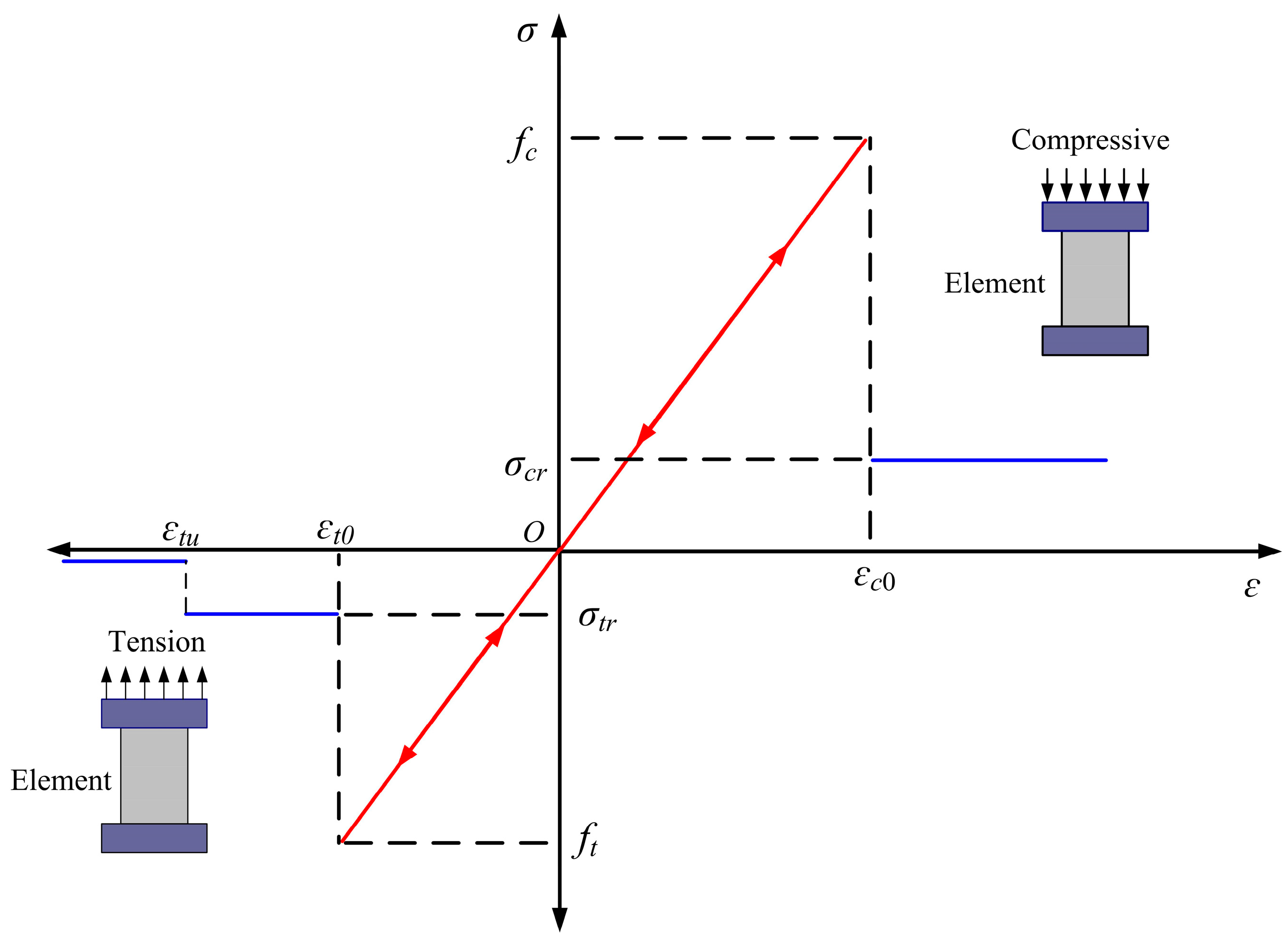
2.2. Evolutionary Damage Principle of RFPA Meso-Elements

RFPA2D uses the four-node iso-parametric element to describe the basic element. All of the elements are considered to be elastic and isotropic. The elastic damage constitutive method is adopted to elaborate the stress–strain relationship. The stress–strain curve of each element is considered as linearly elastic. When the damage threshold is reached, the maximum tensile stress criterion is used to judge the damage and failure of the element in tensile state, and the Mohr-Coulomb criterion is used to judge the damage and failure of the element in compressive and shear state. As the damage progresses, the elastic modulus of the element is gradually degraded. The modified elastic modulus can be expressed as follows:
E = (1 − D) × E0
where E and E0 are the elastic modulus after damage and the initial elastic modulus, respectively; and D is the damage variable.
Figure 1 shows the elastic damage constitutive relation of the element under uniaxial stress state. When shear failure occurs to the elements, the Mohr-Coulomb criterion is adopted:
F = σ 1 σ 3 1 + sin φ 1 sin φ f c
where σ1, σ3 and fc are the maximum principal stress, the minimum principal stress and the uniaxial compressive strength, respectively; and ϕ is the friction angle.
Damage variable D is introduced:
D = 0 ε ε c 0 1 σ c r ε E 0 ε c 0 ε
where σcr is the compressive residual strength and εc0 represents the maximum compressive strain.
When tensile failure occurs to the elements, the following is adopted:
σ 3 f t
Damage variable D is introduced:
D = 0 ε ε t 0 1 σ t r ε E 0 ε t 0 < ε ε t u 1 ε > ε t u
where ft and σtr are the tensile strength of rock and the residual strength of tensile damage, respectively; εt0 and εtu represent the maximum tensile strain and the ultimate tensile strain, respectively. When the maximum tensile strain of the rock element is reached, it loses carrying capacity.

2.3. RFPA Solution for Dynamic Finite Element Equations

The dynamic equilibrium equation for each node in motion can be expressed as [43]:
M u ¨ + C u ˙ + K u = Q
where u ¨ , u ˙ , and u are the constant vectors of displacement, velocity and acceleration at t, respectively. K, M and C are the stiffness matrix, mass matrix and damping matrix of the system, respectively.
By substituting the equations relating velocity, acceleration and displacement in the Newmark method:
u ¨ t + Δ t = 1 β Δ t 2 u t + Δ t u t 1 β Δ t u ˙ t 1 2 β 1 u ¨ t
u ¨ t + Δ t = γ β Δ t u t + Δ t u t + 1 1 β u ˙ t γ 2 β 1 u ¨ t + Δ t Δ t
By substituting Equations (8) and (9) into the dynamic equilibrium Equation (7):
K u t + Δ t = Q u t + Δ t
K = K + 1 β Δ t 2 M + γ β Δ t C
Q t + Δ t = Q t + Δ t + M 1 β Δ t 2 α t + Δ t α t 1 β Δ t α ˙ t 1 2 β 1 α ¨ t + C γ β Δ t α t + Δ t α t + 1 γ β α ˙ t + 1 γ 2 β Δ t α ¨ t
where β and γ are the integration coefficients of the Newmark method. When γ ≥ 0.5, β ≥ 0.25 × (γ + 0.5)2, the Newmark method is unconditionally stable.

3. Numerical Simulation Blasting Process Analysis of Frozen Rock Mass with Ice-filled Cracks

3.1. Model Setup

RFPA2D has been widely used in the numerical simulation of stress wave propagation in conventional jointed rock masses [44,45]. Liang et al. [24] used RFPA2D to carry out the dynamic fracture characteristics of fractured rock under different static stress conditions and compared it with the experimental results of Yang et al. [46]. The simulation results showed that RFPA2D could well simulate crack propagation and stress wave attenuation under dynamic stress, which was in good agreement with the experimental results. In addition, some achievements have been made on the effect of ice-filled cracks on the propagation efficiency of rock explosion stress waves [47]. Therefore, explosion stress wave propagation and crack extension of frozen rock mass with ice-filled cracks during blasting is studied by RFPA2D.
The blasting model of frozen rock mass is 4 m in length and 4 m in height. The mesh size is 0.01 m × 0.01 m. Single-hole blasting is adopted, and the blasting hole radius r is 0.05 m. The blasting load is simplified into triangular waves [24,45]. The loading case is shown in Figure 2. The total duration is 3 × 10⁻⁴ s, and the single-step loading time is 2 × 10⁻⁶ s.
The material parameters of the numerical simulation of rock and ice are shown in Table 1 [48]. Model I is used to study the influence of ice-filled crack thickness d, normal distance R from the ice-filled crack to the center of the blasting hole, loading intensity and loading rate on the propagation process of frozen rock mass explosion stress waves (Table 2). Model II is used to study the influences of the ice-filled crack angle α on the propagation process of frozen rock mass explosion stress waves (Table 3).

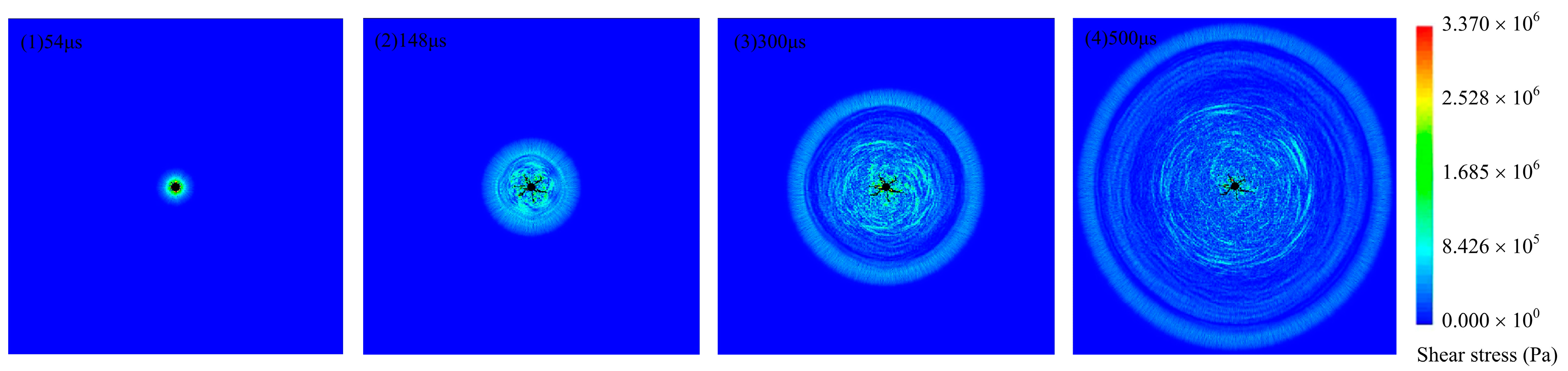
3.2. Analysis of Blasting Failure Process of Intact Frozen Rock Mass

3.2.1. Blasting Failure Process

Figure 3 shows the intact frozen rock mass explosion stress wave propagation and failure process. The cracks produced by blasting mainly occur near the blasting hole. The cracks show a uniform and divergent extension pattern. There is no ice-filled crack in the model, and explosion stress waves propagate equally on the left and right sides. At 0.54 × 10⁻⁴ s, damage elements begin to appear near the blasting hole; and at 1.48 × 10⁻⁴ s, macro blasting cracks are formed. After that, the macro cracks stop extending as the explosion stress wave has propagated out.

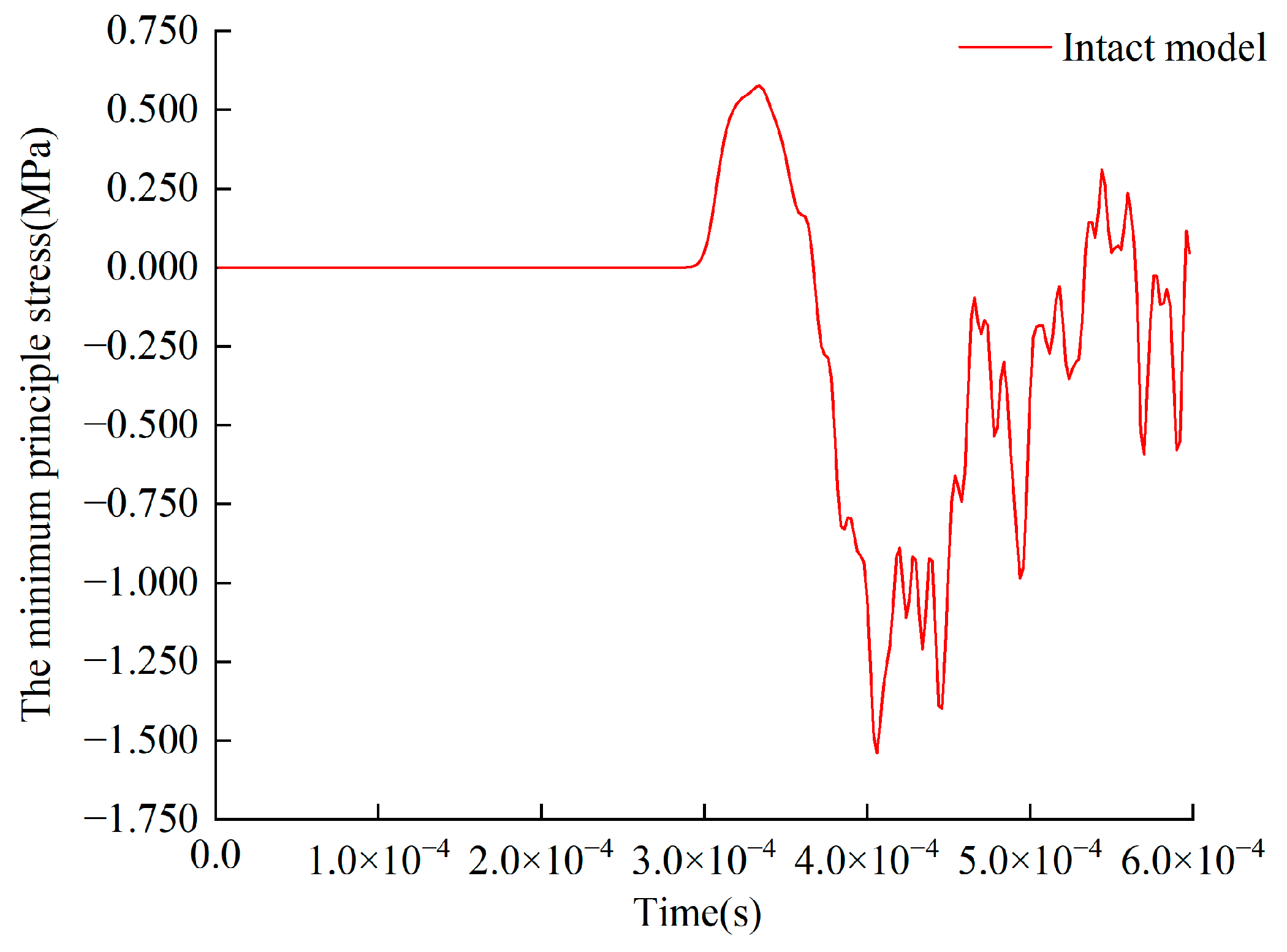
3.2.2. The Minimum Principal Stress at the Monitoring Point A

The monitoring point A is set (3.2 m, 2 m). In RFPA2D, the pressure is positive, and the tensile stress is negative. Before 2.34 × 10⁻⁴ s, the minimum principal stress at the monitoring point A does not change, and the stress waves do not reach the monitoring point A. From 2.34 × 10⁻⁴ s to 3.04 × 10⁻⁴ s, the monitoring point is squeezed by stress waves, showing stress changes; and the peak value of the minimum principal stress is 0.576 MPa. After 3.04 × 10⁻⁴ s, the symbol of the minimum principal stress value changes, and tensile stress is generated at the monitoring point under explosion stress waves. (Figure 4).

3.3. Ice-Filled Crack Thickness d Influence on Blasting Effect of Frozen Rock Mass

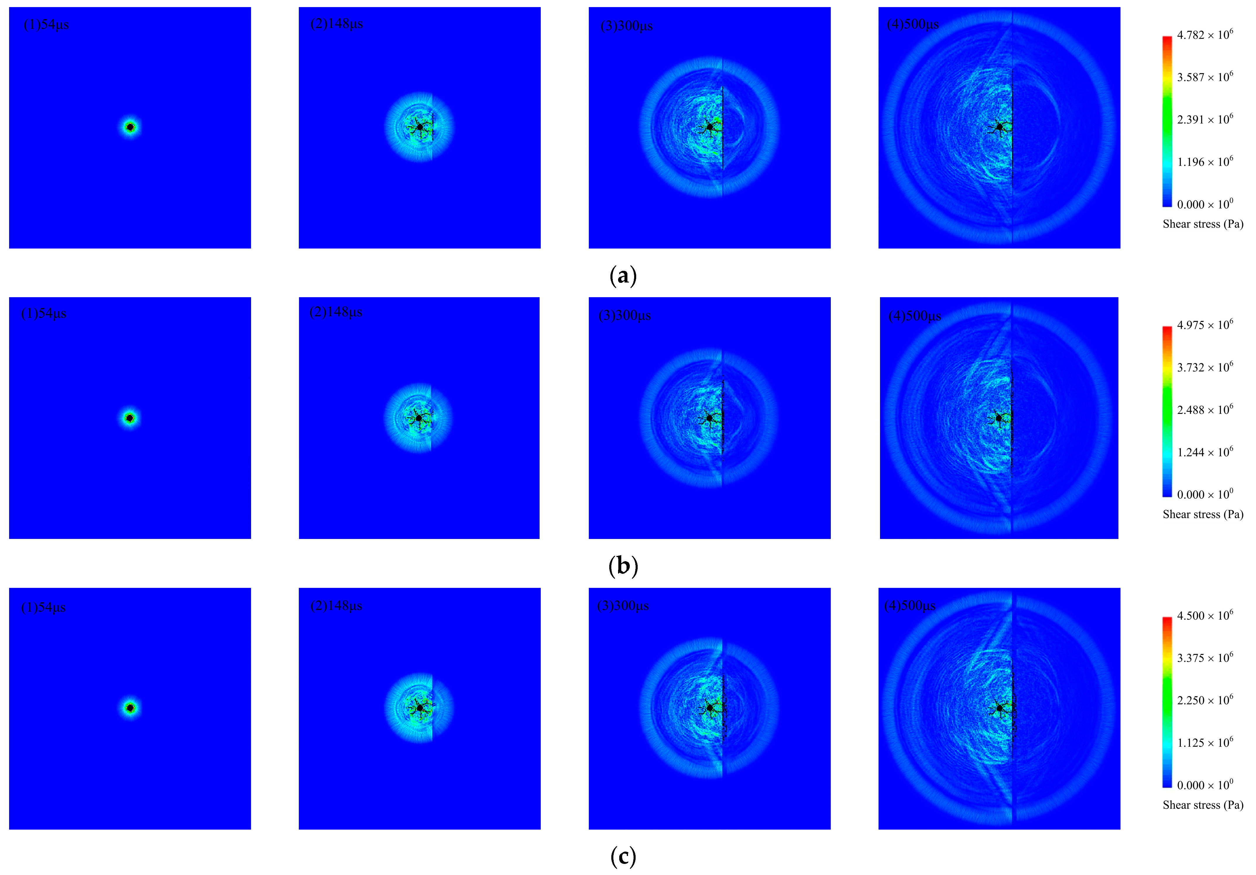
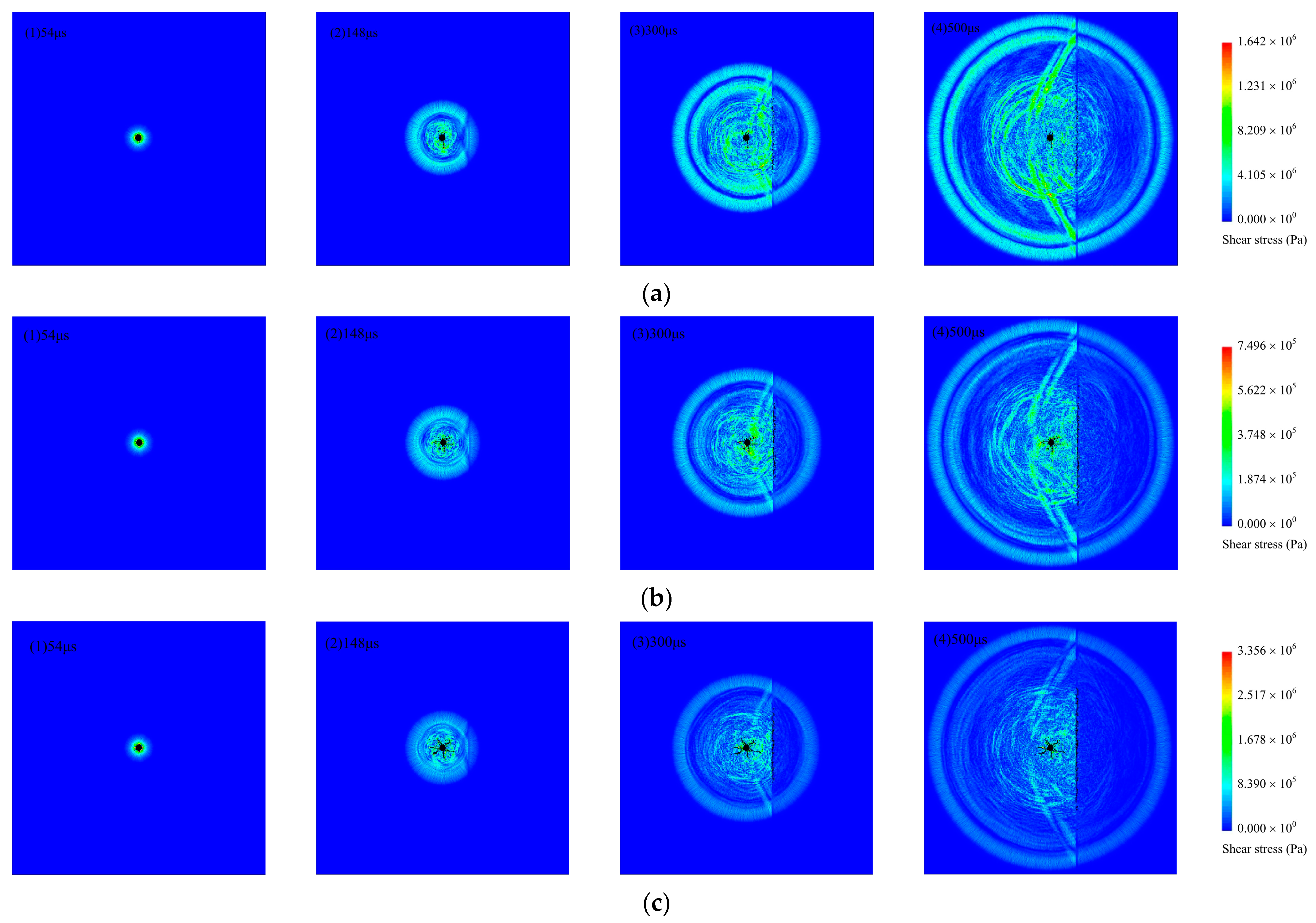
3.3.1. Blasting Failure Process

By comparing the blasting effect of frozen rock with ice-filled cracks of 0.02 m, 0.04 m and 0.08 m thickness distributed in the same normal distance, the following observations are obtained. With the propagation of explosion stress waves, the numerical simulation results are the same as the blasting effect of intact frozen rock mass, and the blasting crack appears first at the blasting hole (Figure 5). Taking d = 0.02 m and R = 0.2 m frozen rock mass with ice-filled cracks as an example, at 0.54 × 10⁻⁴ s, damage elements occur near the blasting hole. At 1.48 × 10⁻⁴ s, the stress wave reaches the ice-filled crack. When the explosion stress wave propagates to the ice-filled crack, reflects and transmits. The reflected wave collides with the incident wave, which reduces both the energy of the incident wave and the explosion range. As the mechanical strength of ice is less than that of rock, damage elements gradually appear in the ice-filled crack first. At 3.00 × 10⁻⁴ s, the explosion stress wave continues to act on the ice-filled crack, and the range of damage elements intensifies. At 5 × 10⁻⁴ s, the stress waves have passed through the ice-filled crack, and the damage range remains stable.
By comparing Figure 5(a4,b4,c4), the damage elements range of the ice-filled crack decreases when the thickness of the ice-filled crack increases. By comparing the crack propagation of the non-ice side with the ice side, the crack propagation of the blasting is induced by the ice-filled crack.

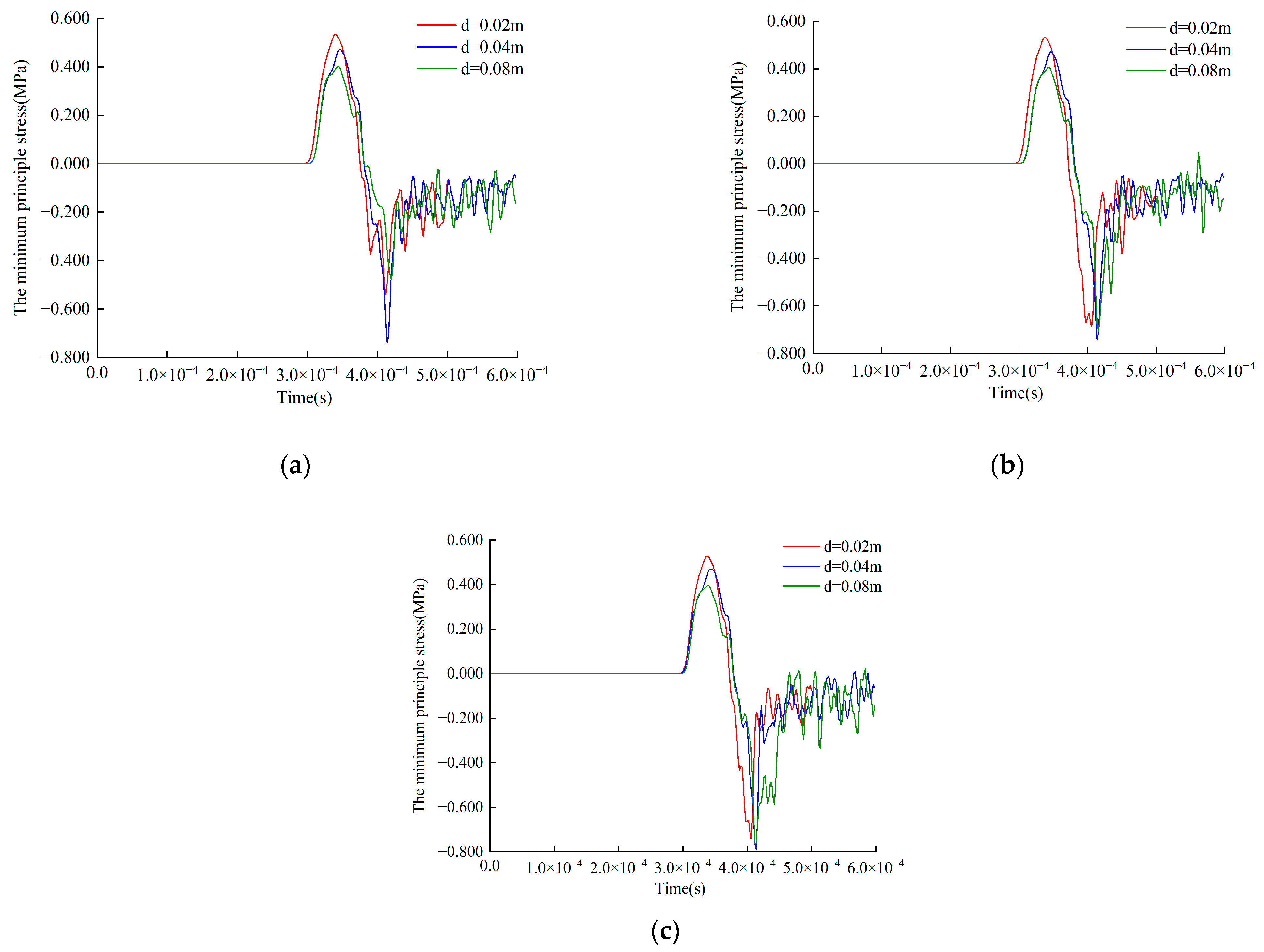
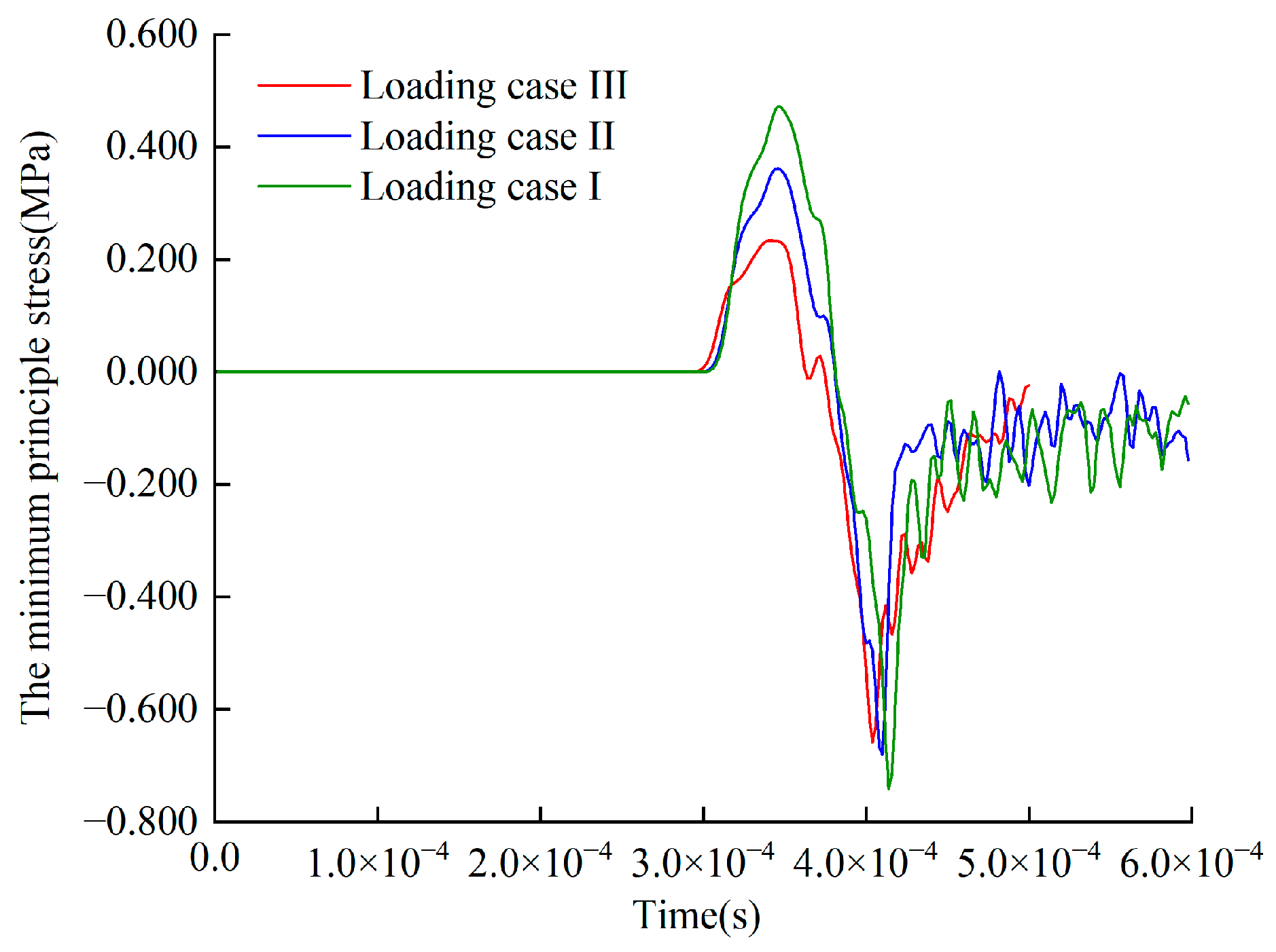
3.3.2. The Minimum Principal Stress at the Monitoring Point A with Different Ice-Filled Crack Thicknesses

By comparing the minimum principal stress at the monitoring point A of ice-filled cracks with different thicknesses (Figure 6), the minimum principal stress presents a positive increase at first, then decreases to a negative fluctuation. The minimum principal stress amplitude is similar to that of the intact frozen rock mass. Taking R = 0.8 m frozen rock mass with ice-filled crack as an example.
When d = 0.02 m, the minimum principal stress is positive and the peak value is 0.528 MPa from 2.90 × 10⁻⁴ s to 3.72 × 10⁻⁴ s. The explosion stress waves produce extrusion effects on the monitoring point. After 3.72 × 10⁻⁴ s, the stress wave propagates through the monitoring point, tensile stress is generated on the monitoring point, and the minimum principal stress turns negative. When d = 0.04 m, the peak value of the minimum principal stress is 0.470 MPa from 2.92 × 10⁻⁴ s to 3.78 × 10⁻⁴ s. When d = 0.08 m, the peak value of the minimum principal stress is 0.395 MPa from 2.96 × 10⁻⁴ s to 3.76 × 10⁻⁴ s. The results show that the minimum principal stress decreases with an increase of ice-filled crack thickness.
At the monitoring point A, the peak value of the minimum principal stress of intact frozen rock mass is 0.576 MPa. The minimum principal stress peak value of frozen rock mass with ice-filled cracks is obviously smaller than that of intact frozen rock mass. It can be seen that the existence of ice-filled cracks inhibits the propagation of explosion stress waves in frozen rock mass.

3.4. Normal Distance R Influence on Blasting Effect of Frozen Rock Mass

3.4.1. Blasting Failure Process

Figure 7 shows the explosion stress wave propagation and failure process of frozen rock mass with different normal distance R. The crack pattern at the blasting hole is similar to that of the intact frozen rock mass, showing a uniform and divergent extension. When d = 0.02 m and 0.04 m, the damage elements ranges have little differences. When d = 0.08 m, the damage elements range have obvious differences. The smaller the normal distance R is, the closer the ice-filled crack is to the blasting hole, the more obvious the explosion stress wave effect is. The thicker the ice-filled crack is, the more apparent that it is affected by normal distance.

3.4.2. The Minimum Principal Stress at the Monitoring Point A with Different Normal Distances

Taking d = 0.04 m frozen rock mass with ice-filled crack as an example (Figure 6). When R = 0.2 m, the peak value of the minimum principal stress is 0.472 MPa from 2.98 × 10⁻⁴ s to 3.82 × 10⁻⁴ s. The explosion stress wave produces extrusion effects on the monitoring point. After 3.72 × 10⁻⁴ s, as the stress wave propagates through the monitoring point, tensile stress is generated on the monitoring point, so it is a negative value. When R = 0.4 m, the peak value of the minimum principal stress is 0.472 MPa from 2.98 × 10⁻⁴ s to 3.82 × 10⁻⁴ s. When R = 0.8 m, the peak value of the minimum principal stress is 0.470 MPa from 2.98 × 10⁻⁴ s to 3.80 × 10⁻⁴ s. When the normal distance between the ice-filled crack and the blasting hole increases, the reduction of the explosion stress wave propagation will decrease slightly.

3.5. Ice-Filled Crack Angle α Influence on Blasting Effect of Frozen Rock Mass

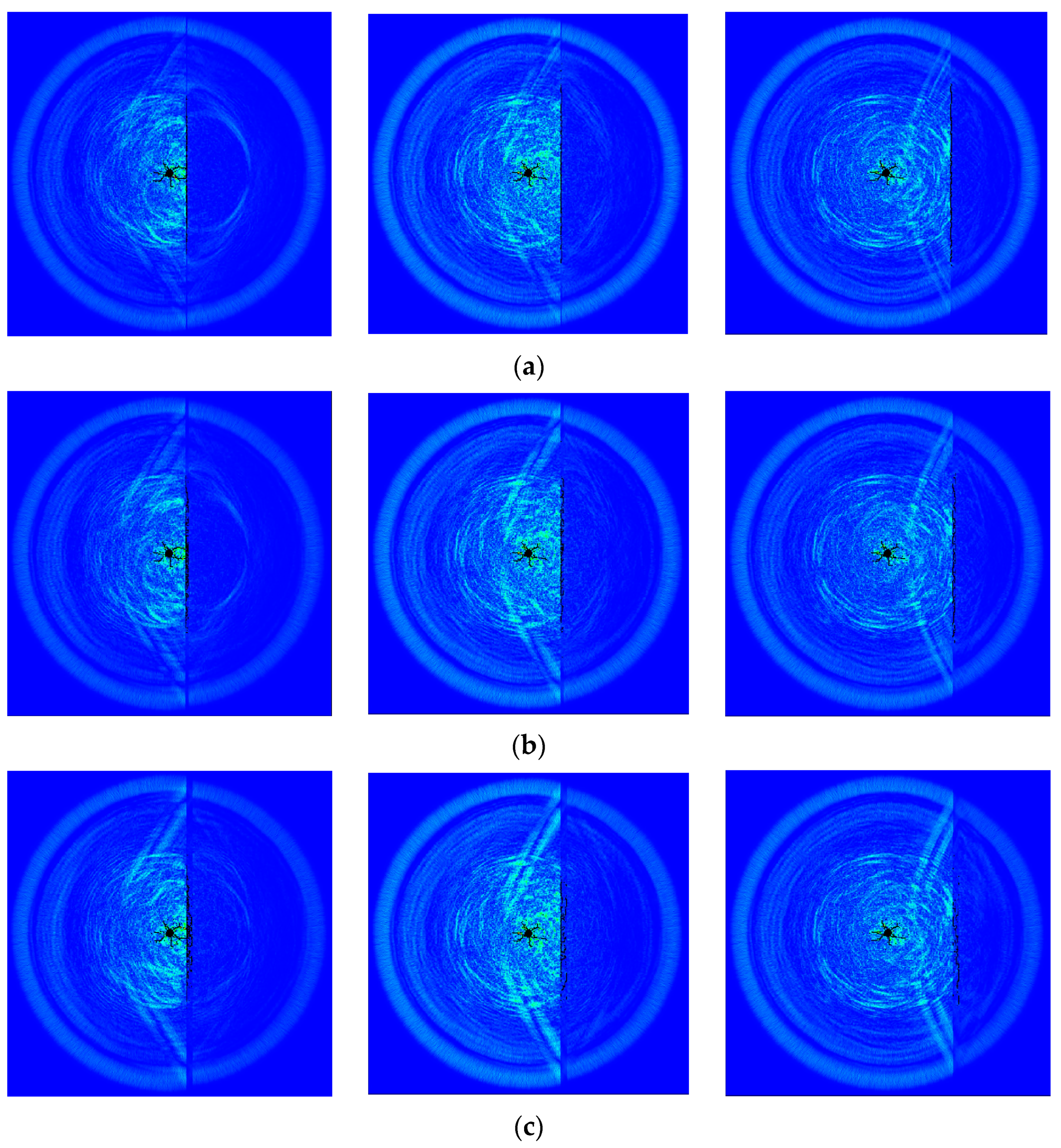
3.5.1. Blasting Failure Process

Figure 8 shows the explosion stress wave propagation and failure process of frozen rock mass with different ice-filled crack angles. Different angles affect the distance from the ice-filled crack to the blasting hole. When d = 0.04 m and R = 0.8 m, the larger the ice-filled crack angle is, the closer the ice-filled crack is to the blasting hole and the wider the damage range of the ice-filled crack.

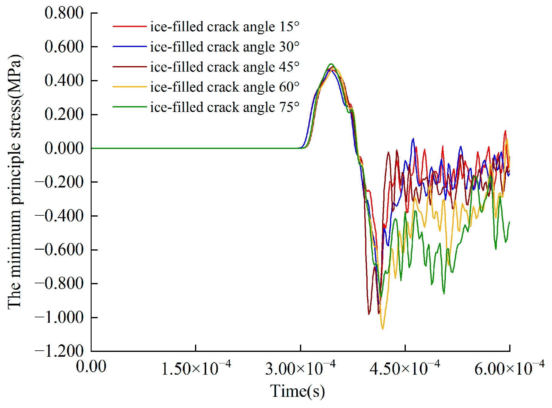
3.5.2. The Minimum Principal Stress at the Monitoring Point A with Different Loading Angles

Taking the frozen rock mass blasting process with the ice-filled crack angle 15° as an example. Before 2.92 × 10⁻⁴ s, the minimum principal stress does not change. From 2.92 × 10⁻⁴ s to 3.80 × 10⁻⁴ s, the peak value of the minimum principal stress is 0.462 MPa. After 3.80 × 10⁻⁴ s, the minimum principal stress turns negative. When the ice-filled crack angle is 30°, 45°, 60°, 75°, the peak value of the minimum principal stress is 0.464 MPa, 0.482 MPa, 0.475 MPa and 0.500 MPa, respectively (Figure 9). An increase of the ice-filled crack angle causes a slight decrease of the minimum principal stress peak value.

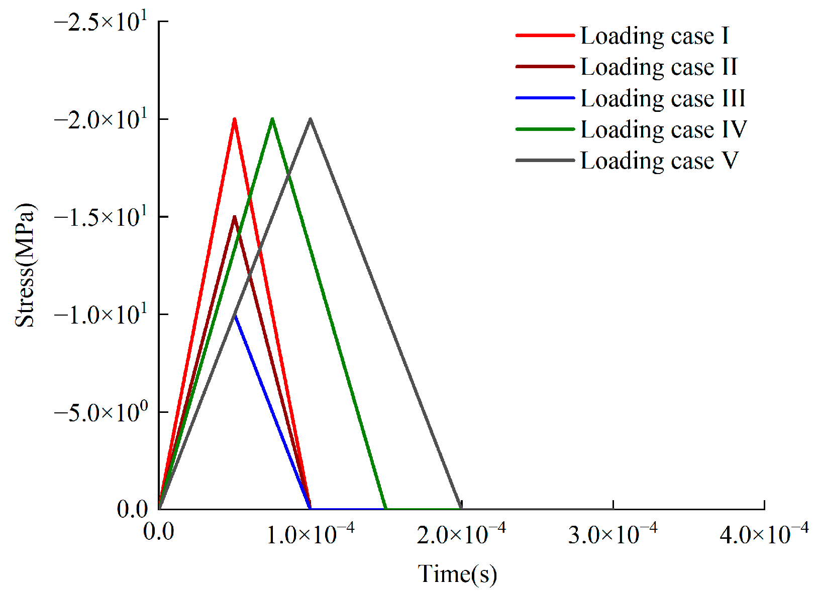
3.6. Loading Intensity Influence on Blasting Effect of Frozen Rock Mass

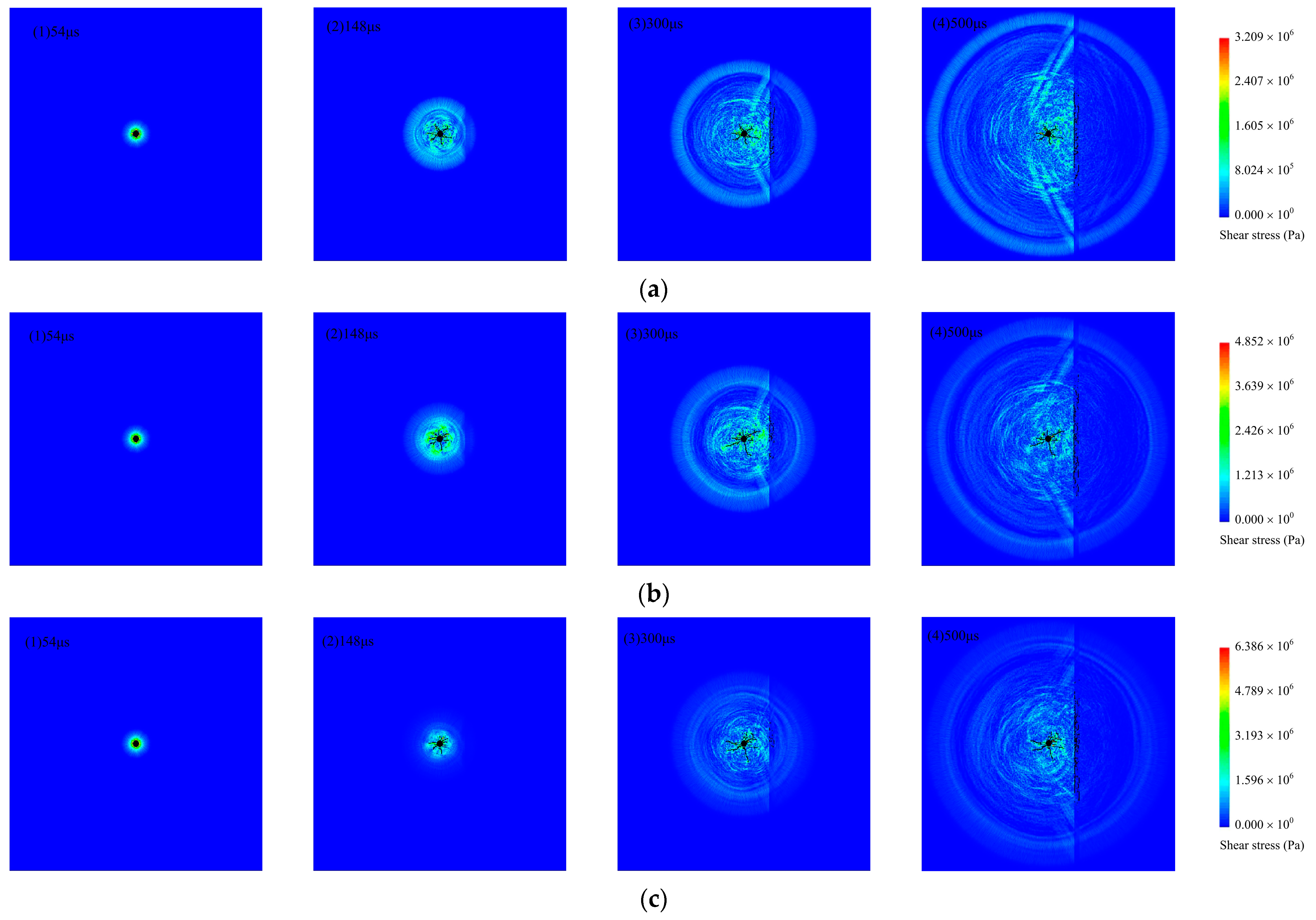
3.6.1. Blasting Failure Process

The mechanical properties of rock materials are affected by the loading peak value, which might influence the explosion stress wave propagation efficiency and blasting effect. Taking d = 0.04 m and R = 0.4 m frozen rock mass as an example to simulate the blasting process with different loading peak values. The failure patterns in loading cases I, II and III at selected times were compared in Figure 10.
With the propagation of the explosion stress wave, the blasting crack appears first at the blasting hole. At 0.54 × 10⁻⁴ s, the blasting hole begins to show damage elements. At 1.48 × 10⁻⁴ s, damage elements gradually appear in the ice-filled crack first. The blasting crack pattern at the blasting hole is obviously different due to different loading intensities. At 3.00 × 10⁻⁴ s, the explosion stress wave continues to impact the ice-filled crack, and the range of damage elements intensifies. At 5 × 10⁻⁴ s, the stress waves have passed through the ice-filled crack and the damage range remains stable. By comparison with Figure 10(a4,b4,c4), as the loading intensity increases, the blasting crack pattern at the blasting hole becomes more apparent, and the damage elements range expands. Also, the effect of explosion stress wave propagation is different.

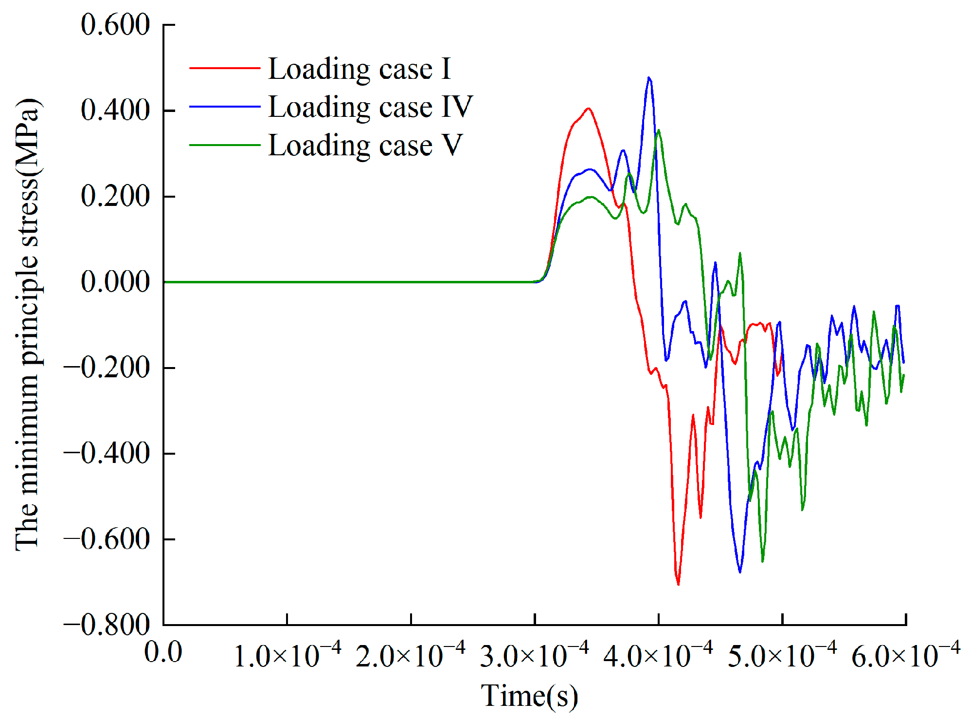
3.6.2. The Minimum Principal Stress at the Monitoring Point A with Different Loading Intensities

Taking the results of frozen rock mass with ice-filled crack blasting process when the loading intensity of the explosion stress wave is 15 MPa as an example. Before 2.96 × 10⁻⁴ s, the minimum principal stress has no change. From 2.96 × 10⁻⁴ s to 3.80×10⁻⁴ s, the peak value of the minimum principal stress is 0.362 MPa, and the explosion stress wave produces extrusion effects on the monitoring point. After 3.80 × 10⁻⁴ s, the minimum principal stress is negative. As the explosion stress wave propagates through the monitoring point, tensile stress is generated on the monitoring point. When the explosion stress wave loading intensity is 10 MPa, the minimum principal stress peak value is 0.233 MPa. When the explosion stress wave loading intensity is 20 MPa, the minimum principal stress peak value is 0.472 MPa (Figure 11). When the loading peak value of the explosion stress wave is larger, the effect of the explosion stress wave on the rock medium is more obvious.

3.7. Loading Rate Influence on Blasting Effect of Frozen Rock Mass

3.7.1. Blasting Failure Process

Different blasting loading rates also have influence on the blasting effect. Taking d = 0.08 m and R = 0.4 m frozen rock mass with ice-filled crack as an example, the failure modes of loading cases I, IV and V at selected times are compared, as shown in Figure 12.
At 0.54 × 10⁻⁴ s, the blasting hole begins to produce damage elements. At 1.48 × 10⁻⁴ s, damage elements gradually appear in the ice-filled crack first. The blasting crack pattern at the blasting hole is different due to the different loading rates. At 3.00 × 10⁻⁴ s, the explosion stress wave continues to impact the ice-filled crack, and the range of damage elements intensifies. The blasting hole crack continues to expand. At 5 × 10⁻⁴ s, the stress waves have passed through the ice-filled crack and the damage range remains stable. By comparison with Figure 12(a4,b4,c4), as the loading rate decreases, the crack length at the blasting hole increases, and the ice-filled crack shows more damage elements.

3.7.2. The Minimum Principal Stress at the Monitoring Point A with Different Loading Rates

By comparing the minimum principal stress on the monitoring point with different loading rates in Figure 13, the following results are observed. Before 2.96 × 10⁻⁴ s, the minimum principal stress stays unchanged. From 2.96 × 10⁻⁴ s to 3.80 × 10⁻⁴ s, the peak value of the minimum principal stress is 0.362 MPa in loading case I. In loading cases IV and V, the variation of the minimum principal stress at the monitoring point A fluctuates dramatically. As the loading waveform is different, the minimum principal stress appears hysteresis, and the transmitted waves generated by the explosion stress waves through the ice-filled cracks are also different.

3.8. Evaluation of the Explosion Stress Wave Attenuation Factor

In order to intuitively evaluate the effects of different ice-filled crack conditions on the explosion stress wave, the attenuation factor B of the explosion stress wave through frozen rock mass is calculated as follows,
B = β c β i β i × 100 %
where βc is the peak value of the minimum principal stress at monitoring point of frozen rock mass under different conditions; and βi is the minimum principal stress value at monitoring points of intact frozen rock mass, which is 0.576 MPa.
The attenuation trend of the explosion stress wave decreases gradually with an increase of thickness, and decreases slightly with an increase of direction, distance and ice-filled crack angle (Table 4).

4. Conclusions

In this work, the stress wave propagation and blasting crack extension mechanism of frozen rock mass with ice-filled cracks are analyzed by RFPA2D. The findings facilitate blasting design and disaster prevention in cold region strip mining. Specifically, the explosion stress wave propagation effect and the damage range are obtained, which consider the geometrical parameters of ice-filled cracks (ice-filled crack thickness D, normal distance R from blasting hole to ice-filled crack, and ice-filled crack angle α), loading intensity and loading rate. The following conclusions can be drawn:
(1)
The divergent crack extension pattern is always maintained at the blasting hole. Affected by explosion wave stress, the damage elements range of the ice-filled crack decreases when the ice-filled crack thickness and normal distance increase.
(2)
The attenuation trend of explosion stress waves decreases with an increase of ice-filled crack thickness, and decreases slightly with an increase of normal distance and ice-filled crack angle.
(3)
The loading intensity and the loading rate have a significant influence on blasting hole fracture patterns. The damage elements range of the ice-filled crack is enlarged when the loading intensity and the loading rate increase. The propagation effect of explosion stress waves is also different.
(4)
The ice-filled crack has a guiding effect on the growth of the blasting crack at the blasting hole. Nevertheless, the existence of ice-filled cracks inhibits the propagation of explosion stress waves in frozen rock mass.
It should be noted that due to the lack of access to information of a real project, in this research, only numerical modelling has been done. It is better to combine these results with experiment and field validation to achieve a more comprehensive method to study frozen rock masses blasting process.

Author Contributions

Conceptualization, T.W. and P.L.; methodology, T.W., C.T. and P.L.; software, T.W., C.T. and J.Y.; validation, T.W., B.Z. and J.Y.; formal analysis, T.W.; investigation, T.W. and B.Z.; resources, T.W., C.T. and P.L.; data curation, T.W. and P.L.; writing—original draft preparation, T.W.; writing—review and editing, C.T. and P.L.; visualization, T.W.; supervision, C.T. and P.L.; project administration, C.T.; funding acquisition, C.T. and P.L. All authors have read and agreed to the published version of the manuscript.

Funding

This research was funded by the National Natural Science Foundation of China (Grant No. 42050201) and the Open Fund of State Key Laboratory of Frozen Soil Engineering (Grant No. SKLFSE202013).

Institutional Review Board Statement

Not applicable.

Informed Consent Statement

Informed consent was obtained from all subjects involved in the study.

Data Availability Statement

The data presented in this study are available on request from the corresponding author. The data are not publicly available due to privacy concerns.

Acknowledgments

Hongda Blasting Engineering Group Co., Ltd. are appreciated for their assistance.

Conflicts of Interest

The authors declare no conflict of interest.

References

  1. Xia, C.C.; Lv, Z.T.; Li, Q.; Huang, J.H.; Bai, X.Y. Transversely Isotropic Frost Heave of Saturated Rock under Unidirectional Freezing Condition and Induced Frost Heaving Force in Cold Region Tunnels. Cold Reg. Sci. Technol. 2018, 152, 48–58. [Google Scholar] [CrossRef]
  2. Liu, N.F.; Li, N.; Li, G.F.; Song, Z.P.; Wang, S.J. Method for Evaluating the Equivalent Thermal Conductivity of a Freezing Rock Mass Containing Systematic Fractures. Rock Mech. Rock Eng. 2022, 55, 7333–7355. [Google Scholar] [CrossRef]
  3. Ma, D.D.; Xiang, H.S.; Ma, Q.Y.; Kaunda, E.E.; Huang, K.; Su, Q.Q.; Yao, Z.M. Dynamic damage constitutive model of frozen silty soil with prefabricated crack under uniaxial load. J. Eng. Mech. 2021, 147, 04021033. [Google Scholar] [CrossRef]
  4. Liu, M.H.; Ma, W.; Niu, F.J.; Luo, J.; Yin, G.A. International Journal of Heat and Mass Transfer Thermal Performance of a Novel Crushed-Rock Embankment Structure for Expressway in Permafrost Regions. Int. J. Heat Mass Transf. 2018, 127, 1178–1188. [Google Scholar] [CrossRef]
  5. Wan, W.K.; Li, C.C. Microscopic and Acoustic Interpretations of the Physics of Rock Burst and the Difference in Fracturing Patterns in Class I and Class II Rocks. Rock Mech. Rock Eng. 2022, 55, 6841–6862. [Google Scholar] [CrossRef]
  6. Li, Y.Z.; Dai, F.; Wei, M.D.; Du, H.B. Numerical Investigation on Dynamic Fracture Behavior of Cracked Rocks under Mixed Mode I/II Loading. Eng. Fract. Mech. 2020, 235, 107176. [Google Scholar] [CrossRef]
  7. Zhang, F.P.; Peng, J.Y.; Qiu, Z.G.; Chen, Q.K.; Li, Y.H.; Liu, J.P. Rock-like Brittle Material Fragmentation under Coupled Static Stress and Spherical Charge Explosion. Eng. Geol. 2017, 220, 266–273. [Google Scholar] [CrossRef]
  8. Cai, J.G.; Zhao, J. Effects of Multiple Parallel Fractures on Apparent Attenuation of Stress Waves in Rock Masses. Int. J. Rock Mech. Min. Sci. 2000, 37, 661–682. [Google Scholar] [CrossRef]
  9. Fan, L.F.; Ma, G.W.; Li, J.C. Nonlinear Viscoelastic Medium Equivalence for Stress Wave Propagation in a Jointed Rock Mass. Int. J. Rock Mech. Min. Sci. 2012, 50, 11–18. [Google Scholar] [CrossRef]
  10. Yari, M.; Bagherpour, R.; Jamali, S.; Asadi, F. Selection of Most Proper Blasting Pattern in Mines Using Linear Assignment Method: Sungun Copper Mine. Arch. Min. Sci. 2015, 60, 375–386. [Google Scholar]
  11. Lak, M.; Fatehi Marji, M.; Yarahmadi Bafghi, A.; Abdollahipour, A. Analytical and numerical modeling of rock blasting operations using a two-dimensional elasto-dynamic Green’s function. Int. J. Rock Mech. Min. Sci. 2019, 114, 208–217. [Google Scholar] [CrossRef]
  12. Pyrak-Nolte, L.J.; Morris, J.P. Single fractures under normal stress: The relation between fracture specific stiffness and fluid flow. Int. J. Rock Mech. Min. Sci. 2000, 18, 245–262. [Google Scholar] [CrossRef]
  13. Li, J.C.; Ma, G.W. Experimental Study of Stress Wave Propagation across a Filled Rock Joint. Int. J. Rock Mech. 2009, 46, 471–478. [Google Scholar] [CrossRef]
  14. Yari, M.; Monjezi, M.; Bagherpour, R. A novel investigation in blasting operation management using decision making methods. Rud. Geol. Naft. Zb. 2014, 29, 69–79. [Google Scholar]
  15. Butt, H.S.U.; Xue, P.; Jiang, T.Z.; Wang, B. Parametric identification for material of viscoelastic SHPB from wave propagation data incorporating geometrical effects. Int. J. Mech. Sci. 2015, 91, 46–54. [Google Scholar] [CrossRef]
  16. Chen, X.; Li, J.C.; Cai, M.F.; Zou, Y.; Zhao, J. A Further Study on Wave Propagation Across a Single Joint with Different Roughness. Rock Mech. Rock Eng. 2016, 49, 2701–2709. [Google Scholar] [CrossRef]
  17. Kumar, S.; Tiwari, G.; Parameswaran, V.; Das, A. Rate-dependent mechanical behavior of jointed rock with an impersistent joint under different infill conditions. J. Rock. Mech. Geotech. 2022, 14, 1380–1389. [Google Scholar] [CrossRef]
  18. Luo, H.H.; Yang, R.S.; Ma, X.M.; Zuo, J.J.; Zhang, Y.T.; Li, C.X. The Influence of Prefabricated Cracks at Different Angles on the Propagation Characteristics of Main Cracks in Slot Blasting. J. Mater. Eng. Perform. 2022. [Google Scholar] [CrossRef]
  19. Ram, O.; Sadot, O. Implementation of the exploding wire technique to study blastwave-structure interaction. Exp. Fluids. 2012, 53, 1335–1345. [Google Scholar] [CrossRef]
  20. Gharehdash, S.; Barzegar, M.; Palymskiy, I.B.; Fomin, P.A. Blast induced fracture modelling using smoothed particle hydrodynamics. Int. J. Impact Eng. 2020, 135, 103235. [Google Scholar] [CrossRef]
  21. Jeong, H.; Jeon, B.; Choi, S.; Jeon, S. Fracturing behavior around a blasthole in a brittle material under blasting loading. Int. J. Impact Eng. 2020, 140, 103562. [Google Scholar] [CrossRef]
  22. Pramanik, R.; Deb, D. Implementation of Smoothed Particle Hydrodynamics for Detonation of Explosive with Application to Rock Fragmentation. Rock Mech. Rock Eng. 2015, 48, 1683–1698. [Google Scholar] [CrossRef]
  23. Zhou, W.H.; Hu, C.Z.; Bao, J.; Zheng, J.J.; Liang, R. Numerical study on crack propagation and stress wave propagation during blasting of jointed rock mass. Chin. J. Theor. Appl. Mech. 2022, 54, 2501–2512. (In Chinese) [Google Scholar]
  24. Liang, Z.Z.; Qian, X.K.; Zhang, Y.F.; Liao, Z.Y. Numerical Simulation of Dynamic Fracture Properties of Rocks under Different Static Stress Conditions. J. Cent. South Univ. 2022, 29, 624–644. [Google Scholar] [CrossRef]
  25. Bendezu, M.; Romanel, C.; Roehl, D. Finite element analysis of blast-induced fracture propagation in hard rocks. Comput. Struct. 2017, 182, 1–13. [Google Scholar] [CrossRef]
  26. Dehghan Banadaki, M.M.; Mohanty, B. Numerical simulation of stress wave induced fractures in rock. Int. J. Impact Eng. 2012, 40–41, 16–25. [Google Scholar] [CrossRef]
  27. Zhao, J.J.; Zhang, Y.; Ranjith, P.G. Numerical Simulation of Blasting-Induced Fracture Expansion in Coal Masses. Int. J. Rock Mech. Min. Sci. 2017, 100, 28–39. [Google Scholar] [CrossRef]
  28. Yari, M.; Ghadyani, D.; Jamali, S. Development of a 3D numerical model for simulating a blast wave propagation system considering me position of the blasting hole and in-situ discontinuities. Rud. Geol. Naft. Zb. 2022, 37, 67–78. [Google Scholar]
  29. Lak, M.; Fatehi Marji, M.; Yarhamadi Bafghi, A.R.; Abdollahipour, A. Discrete element modeling of explosion-induced fracture extension in jointed rock masses. J. Min. Environ. 2019, 10, 125–138. [Google Scholar]
  30. Hajibagherpour, A.R.; Mansouri, H.; Bahaaddini, M. Numerical modeling of the fractured zones around a blasthole. Comput. Geotech. 2020, 123, 103535. [Google Scholar] [CrossRef]
  31. Ning, Y.J.; Yang, J.; Ma, G.W.; Chen, P.W. Modelling rock blasting considering explosion gas penetration using discontinuous deformation analysis. Rock Mech. Rock Eng. 2011, 44, 483–490. [Google Scholar] [CrossRef]
  32. Johnson, G.R. Linking of Lagrangian particle methods to standard finite element methods for high velocity impact computations. Nucl. Eng. Des. 1994, 150, 265–274. [Google Scholar] [CrossRef]
  33. Fakhimi, A.; Lanari, M. DEM-SPH simulation of rock blasting. Comput. Geotech. 2014, 55, 158–164. [Google Scholar] [CrossRef]
  34. Yue, Z.W.; Zhou, J.; Feng, C.; Wang, X.; Peng, L.Z.; Cong, J.Y. Coupling of material point and continuum discontinuum element methods for simulating blast-induced fractures in rock. Comput. Geotech. 2022, 144, 104629. [Google Scholar] [CrossRef]
  35. Wu, D.; Li, H.B.; Shao, Z.S.; Chen, S.H.; Zhou, C.H.; Liu, L.W. Effects of infilling materials on mechanical behaviors and cracking process of pre-cracked rock: Insights from a hybrid continuum-discontinuum method. Eng. Fract. Mech. 2021, 253, 107843. [Google Scholar] [CrossRef]
  36. Yan, C.Z.; Xie, X.; Ren, Y.H.; Ke, W.H.; Wang, G. A FDEM-based 2D coupled thermal-hydro-mechanical model for multiphysical simulation of rock fracturing. Int. J. Rock Mech. Min. Sci. 2022, 149, 104964. [Google Scholar] [CrossRef]
  37. Trivino, L.F.; Mohanty, B. Assessment of crack initiation and propagation in rock from explosion-induced stress waves and gas expansion by cross-hole seismometry and FEM-DEM method. Int. J. Rock Mech. Min. Sci. 2015, 77, 287–299. [Google Scholar] [CrossRef]
  38. Zhao, A.P.; Feng, C.; Guo, R.K.; Li, S.H.; Jia, J.J. Effect of joints on blasting and stress wave propagation. Chin. J. Rock Mech. Eng. 2018, 37, 2027–2036. (In Chinese) [Google Scholar]
  39. Bai, Y.; Shan, R.L.; Ju, Y.; Wu, Y.X.; Tong, X.; Han, T.Y.; Dou, H.Y. Experimental study on the strength, deformation and crack evolution behaviour of red sandstone samples containing two ice-filled fissures under triaxial compression. Cold Reg. Sci. Technol. 2020, 174, 103061. [Google Scholar] [CrossRef]
  40. Wu, N.; Liang, Z.Z.; Li, Y.; Qian, X.K.; Gong, B. Effect of confining stress on representative elementary volume of jointed rock masses. Geomech. Eng. 2019, 18, 627–638. [Google Scholar]
  41. Zhu, W.C.; Liu, J.; Yang, T.H.; Sheng, J.C.; Elsworth, D. Effects of local rock heterogeneities on the hydromechanics of fractured rocks using a digital-image-based technique. Int. J. Rock Mech. Mining Sci. 2006, 43, 1182–1199. [Google Scholar] [CrossRef]
  42. Erarslan, N.; Liang, Z.Z.; Williams, D.J. Experimental and Numerical Studies on Determination of Indirect Tensile Strength of Rocks. Rock Mech. Rock Eng. 2012, 45, 739–751. [Google Scholar] [CrossRef]
  43. Zhu, W.C.; Niu, L.L.; Li, S.H.; Xu, Z.H. Dynamic Brazilian Test of Rock under Intermediate Strain Rate: Pendulum Hammer-Driven SHPB Test and Numerical Simulation. Rock Mech. Rock Eng. 2015, 48, 1867–1881. [Google Scholar] [CrossRef]
  44. Qian, X.K.; Liang, Z.Z.; Liao, Z.Y. A Three-Dimensional Numerical Investigation of Dynamic Fracture Characteristics of Rock Specimens with Preexisting Surface Flaws. Adv. Civ. Eng. 2018, 2018, 8027582. [Google Scholar] [CrossRef]
  45. Qian, X.K.; Liang, Z.Z.; Liao, Z.Y.; Wang, K. Numerical investigation of dynamic fracture in rock specimens containing a pre-existing surface flaw with different dip angles. Eng. Frac. Mech. 2020, 223, 106675. [Google Scholar] [CrossRef]
  46. Li, P.F.; Wang, T.T.; Tang, C.A.; Zhang, B.B. Propagation Characteristics of Explosion Stress Wave in Ice-filled Rock Mass. Blasting 2022, 39, 44–52. (In Chinese) [Google Scholar]
  47. Yang, X.; Pu, C.J.; Tang, X.; Xiao, Z.X.; Guan, S.H.; Liao, T. Experimental study of effects of manual crack on blasting cracks propagation. Blasting 2014, 31, 26–31. (In Chinese) [Google Scholar]
  48. Wang, T.T.; Li, P.F.; Tang, C.A.; Zhang, B.B.; Yu, J.; Geng, T. Tensile Characteristics and Fracture Mode of Frozen Fractured Rock Mass Based on Brazilian Splitting Test. Appl. Sci. 2022, 12, 11788. [Google Scholar] [CrossRef]
Figure 1. Elastic damage constitutive relation of the element under uniaxial stress state.
Sustainability 15 04616 g001
Figure 2. Explosion stress waves applied on the blasting hole.
Sustainability 15 04616 g002
Figure 3. Intact frozen rock mass explosion stress wave propagation and failure process.
Sustainability 15 04616 g003
Figure 4. The minimum principal stress during blasting at intact frozen rock monitoring point.
Sustainability 15 04616 g004
Figure 5. Explosion stress wave propagation and failure process of frozen rock mass with different ice-filled crack thicknesses (the normal distance R is 0.2 m). (a1a4) d = 0.02 m; (b1b4) d = 0.04 m; (c1c4) d = 0.08 m.
Sustainability 15 04616 g005
Figure 6. The minimum principal stress during blasting at frozen rock mass monitoring point with different ice-filled crack thicknesses. (a) R = 0.2 m; (b) R = 0.4 m; (c) R = 0.8 m.
Sustainability 15 04616 g006
Figure 7. Explosion stress wave propagation and failure process of frozen rock mass with different normal distance R. (a) d = 0.02 m; (b) d = 0.04 m; (c) d = 0.08 m.
Sustainability 15 04616 g007
Figure 8. Damage and cracking after blasting of frozen rock mass with different angles. (a) 15°; (b) 30°; (c) 45°; (d) 60°; (e) 75°.
Sustainability 15 04616 g008
Figure 9. The minimum principal stress during blasting at frozen rock mass monitoring point with different ice-filled crack angles.
Sustainability 15 04616 g009
Figure 10. Damage and cracking after blasting of frozen rock mass with different loading intensities. (a1a4) loading case III; (b1b4) loading case II; (c1c4) loading case I.
Sustainability 15 04616 g010
Figure 11. The minimum principal stress during blasting at frozen rock mass monitoring point with different loading intensities.
Sustainability 15 04616 g011
Figure 12. Damage and cracking after blasting of frozen rock mass with different loading rates. (a1a4) Loading case I; (b1b4) Loading case IV; (c1c4) Loading case V.
Sustainability 15 04616 g012
Figure 13. The minimum principal stress during blasting at ice-filled crack frozen rock mass monitoring point with different peak loading values.
Sustainability 15 04616 g013
Table 1. Material parameters of the model.
Elasticity Modulus
(MPa)
mCompressive Strength
(MPa)
mPoisson RatioFriction AngleDensity
(kg × m−3)
Rock32,000514750.330°2600
Ice6000108100.3526.5°917
Table 2. Calculation Model I.
Explosion ModelIce-Filled Crack Thickness d (m)
0.020.040.08
R0.2 mSustainability 15 04616 i001Sustainability 15 04616 i002Sustainability 15 04616 i003Sustainability 15 04616 i004
0.4 mSustainability 15 04616 i005Sustainability 15 04616 i006Sustainability 15 04616 i007
0.8 mSustainability 15 04616 i008Sustainability 15 04616 i009Sustainability 15 04616 i010
Table 3. Calculation Model II.
Explosion ModelIce-Filled Crack Angles α (°)
R = 0.8 m
d = 0.04 m
Sustainability 15 04616 i01115°30°45°
Sustainability 15 04616 i012Sustainability 15 04616 i013Sustainability 15 04616 i014
60°75°
Sustainability 15 04616 i015Sustainability 15 04616 i016
Table 4. Explosion stress wave attenuation at monitoring points of frozen rock mass under different conditions.
No.Width (m)R (m)Angle (°)Loading CaseAttenuation (%)
10.020.20I7.128
20.020.40I7.292
30.020.80I8.333
40.040.20I18.056
50.040.40I18.056
60.040.80I18.403
70.080.20I30.035
80.080.40I29.689
90.080.80I31.424
100.040.815I19.792
110.040.830I19.444
120.040.845I16.319
130.040.860I17.535
140.040.875I13.194
Disclaimer/Publisher’s Note: The statements, opinions and data contained in all publications are solely those of the individual author(s) and contributor(s) and not of MDPI and/or the editor(s). MDPI and/or the editor(s) disclaim responsibility for any injury to people or property resulting from any ideas, methods, instructions or products referred to in the content.

