Article

Experimental Study on Shear Strength Parameters of Round Gravel Soils in Plateau Alluvial-Lacustrine Deposits and Its Application

1
Faculty of Public Safety and Emergency Management, Kunming University of Science and Technology, Kunming 650093, China
2
College of Civil and Architectural Engineering, Yunnan Agricultural University, Kunming 650201, China
3
Yunnan Construction Investment No. 6 Construction Co., Ltd., Yuxi 653199, China
4
Zhongxing Shuchuang (Yunnan) Technology Co., Ltd., Kunming 650011, China
*
Author to whom correspondence should be addressed.
Sustainability 2023, 15(5), 3954; https://doi.org/10.3390/su15053954
Submission received: 29 December 2022 / Revised: 18 February 2023 / Accepted: 19 February 2023 / Published: 22 February 2023
(This article belongs to the Special Issue Advances in Rock Mechanics and Geotechnical Engineering)

Abstract

:
The shear strength parameters of conglomerate soils are crucial to the stability analysis of foundation support when excavating and supporting ultra-deep foundation pits in the highland alluvial lacustrine layer. The difference in water content of conglomerate soils in different regions will directly affect the values of shear strength parameters. At the same time, more research on the shear strength of conglomerate soils under different water contents is required. In this study, a series of large-scale direct shear tests were carried out on the round gravel soil in the plateau alluvial-lacustrine deposit, and the round gravel soil’s shear strength curves under natural and saturated conditions and water content were obtained. The influence of different water content on the shear strength characteristics of the round gravel soil was discussed, and the shear strength parameters of the round gravel soil with different water content were used in the numerical simulation of ultra-deep foundation pit excavation and support. The stress and deformation laws of the foundation pit support were analyzed. The results show that the peak strength of the round gravel soil in the natural water content state appears between 30% and 45% of the shear displacement, while the peak strength in the saturated water content state appears around 45–55% of the shear displacement. The shear strength tends to be stable or slightly weakened with the increase of the shear displacement. The angle of internal friction and cohesion of round gravel soil in the natural water content state is greater than those in the saturated water content state. The simulation of the foundation excavation support shows that the shear strength parameter of the round gravel soil influences the force deformation of the support structure. The higher the water content of the round gravel soil, the more the shear strength parameter affects the soil displacement. The research results can provide some reference for optimizing project design parameters.

1. Introduction

Plateau alluvial strata are formed by the joint action of river alluvium and lake marsh sedimentation. Generally, they consist of rounded gravels with high foundation strength and are often used for urban construction sites [1,2,3,4,5]. Influenced by geological activities on the Yunnan-Guizhou Plateau, rounded gravel strata are widely distributed in Kunming [6] and buried at a shallow depth. Influenced by the formation conditions, time, and geographical area of round gravel soil, the maximum particle size of round gravel soil reaches 60–80 mm, and the poor grading, strong permeability, and interparticle clay composition lead to the strength of round gravel soil are larger than general soil [7,8,9,10,11,12]. To a certain extent, these characteristics make round gravel soils have strong engineering applications, leading scholars at home and abroad to focus more on engineering applications or theoretical studies. In contrast, research on shear strength parameters of round gravel soils has yet to receive more attention [13,14,15]. With the urban construction of Kunming city, more and more projects are built on round gravel strata. The shear strength and stress-strain characteristics of round gravel soils usually need to be considered in the design calculation of foundation pits. At the same time, there are few relevant studies on round gravel soils, resulting in most foundation pits in the design calculation can only be taken according to empirical values, which seriously affects the stability of foundation pit construction. Especially nowadays, foundation pit projects are developing in the direction of super large and deep. During design calculation, a slight deviation of soil shear strength parameters greatly impacts foundation pits’ stability. According to statistics, the annual failure rate of foundation pits in China reaches more than 10–15%, which causes huge economic losses to China and threatens the safety of residents and urban construction, mainly due to the lack of experience in design and construction. Therefore, it is necessary to conduct a systematic study on the shear strength of round gravel soil parameters for systematic research to avoid the experience of errors leading to safety accidents in foundation pit construction.
With the continuous in-depth research on the physical and mechanical properties of coarse-grained soils by scholars at home and abroad, round gravel soils have also been widely studied. In terms of experimental shear properties of round gravel soil, Tang Kaishun et al. [16] conducted a large triaxial compression test on round gravel soil in the Nanning area under different compaction conditions and analyzed and compared the effect of compaction on shear strength parameters of round gravel soil under various levels of surrounding pressure. The results showed that the shear strength of round gravel soil was positively correlated with compaction and significantly improved compared with empirical engineering values. Ma Shaokun et al. [17,18] conducted a large drained dynamic triaxial test on round gravel soil in a saturated state. They analyzed the variation of cumulative strain, stress-strain hysteresis loop, and pore pressure of the round gravel soil under different relative compactness, dynamic stress amplitude, and the number of vibrations. Stark et al. [19] investigated the effect of particle shape on the internal friction angle of beach gravel soils by direct shear experiments on beach gravels. The results showed that elliptical gravels have a greater effect on the internal friction angle of beach gravel soils, and increasing the content of elliptical particles in gravel soils can significantly increase their internal friction angle magnitude. Enomoto et al. [20] investigated the strength, deformation properties, and small strain properties of undisturbed well-graded gravel soils by a series of medium and large triaxial and unconfined compression tests. The results showed that the shear modulus might be large when the small strain properties of gravel soils are determined by the dynamic method in the laboratory. The dynamic method converges to the static method test results when the wavelength is significantly larger than the mean diameter. Secondly, when gravel soil’s dry density and homogeneity coefficient exceeded certain values, the dynamic and static shear modulus values of in-situ and remodeled soils increased with the increase of dry density. For the study of the intrinsic model of round gravel soils. Chen Chen et al. [21] proposed a modified Duncan-Chang intrinsic model for round gravel soil based on the unified disturbance degree function based on the disturbance state theory with the relative density Dr as the disturbance parameter. Saberi et al. [22] established a new elastic-plastic intrinsic model for gravel soil based on double surface plasticity and critical state geomechanics. To analyze the piling characteristics of round gravel, Liu Gang et al. [23] proposed a construction method of particle ellipsoid model for round gravel, established an ellipsoid model database, and derived the piling characteristics of round gravel through numerical piling tests and comparative analysis with the results of cylinder piling tests. As for the research on the engineering application of round gravel soil, Ou Xiaoduo et al. [24] used ABAQUS to simulate the deep foundation excavation of round gravel-mudstone strata and analyze the effect of deep foundation excavation on the double-row pile support structure. Ni Xiaorong et al. [25] studied the applicability of long-spiral bored piles in round gravel strata. They proposed a new construction process of secondary pressurized piles for construction problems.
In summary, scholars at home and abroad have studied the strength, deformation, and other properties of round gravel soil influencing factors and have achieved certain research results. However, most research focuses on the engineering application of round gravel formation. Little attention is paid to the influence of water on the mechanical properties of round gravel soil, and the research results need to be more comprehensive. Due to the special geographical location and formation conditions of alluvial plateau strata, the shear strength characteristics of round gravel soil in the formation are different from those in other regions. They are greatly affected by the change in moisture content. At the same time, scholars at home and abroad have paid less attention to the physical and mechanical characteristics of round gravel soil affected by moisture content. Therefore, based on the foundation pit project of the 14th water purification plant in Kunming, this study carried out a large-scale direct shear experiment on the round gravel soil of the alluvial plateau layer, obtained the shear strength parameters of round gravel, and analyzed the change law of the shear resistance characteristics of round gravel soil under different moisture cuts.

2. Experimental Study of Shear Property Parameters of Round Gravel Soil

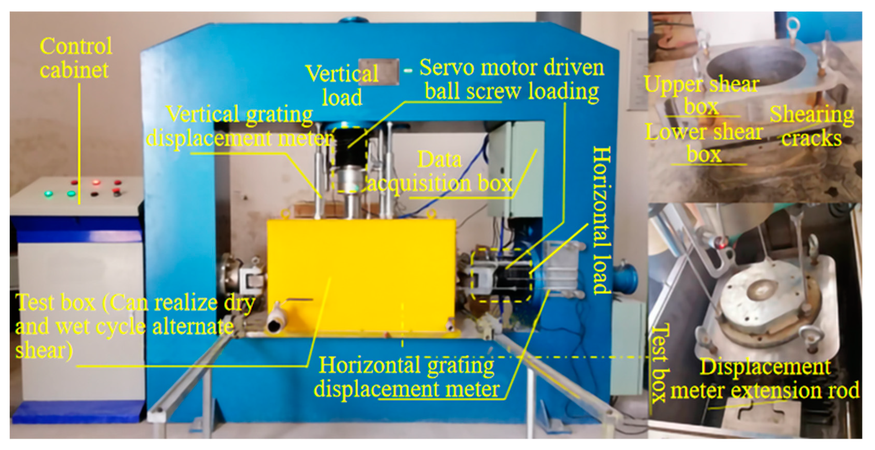
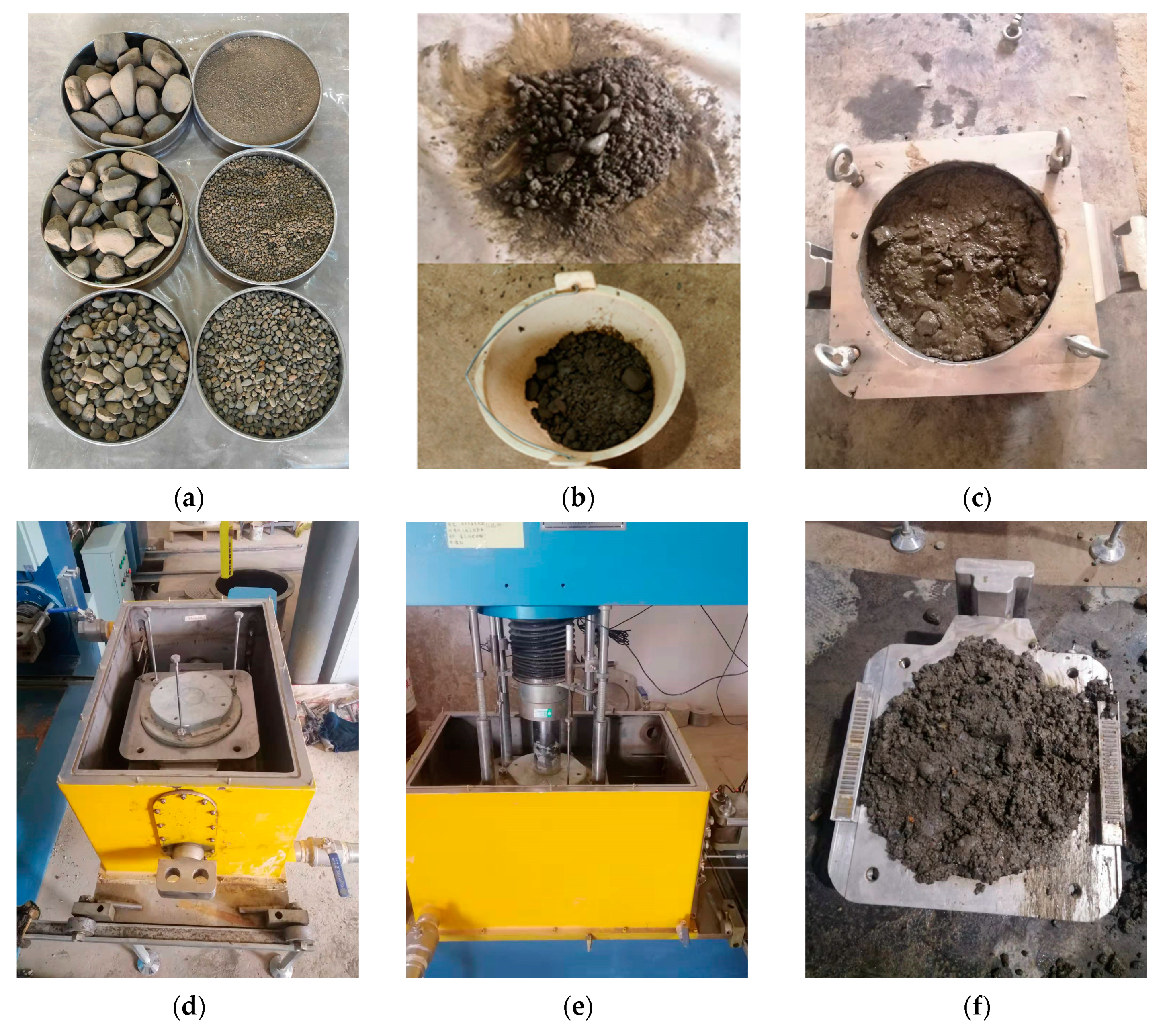
2.1. Testing Instruments

The experiment uses a DHJ-30 type coarse-grained soil stacked ring shear experimental machine, see Figure 1. the experimental machine adopts the plate frame structure with a host size of 2000 × 800 × 1400 mm. The equipment shear box is square outside and round inside, the size of Φ300 × 300 mm, the maximum axial pressure is 300 kN (normal stress 4.3 MPa), the maximum horizontal thrust is 300 kN, force sensor resolution is 0.1 kN. It can realize stress and strain type shear, in which the shear moving speed is 0.001~5 mm/min.

2.2. Experimental Soil Samples

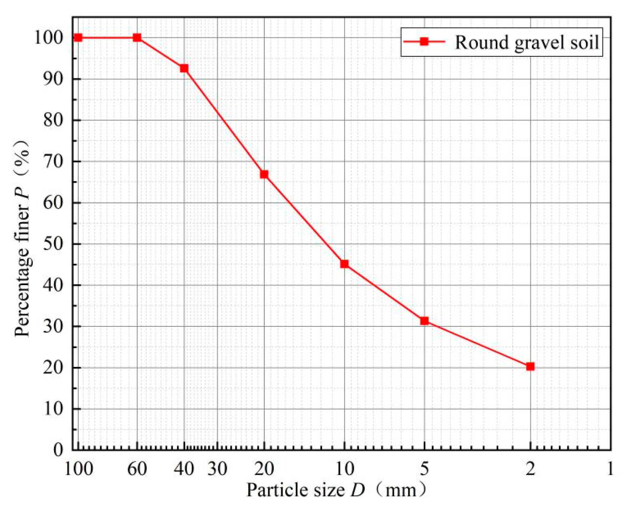
2.2.1. Round Gravel Soil Particle Size Composition

The experimental soil sample was selected from the round gravel soil of the foundation pit project of fourteen water quality purification plants in Panlong District, Kunming, at a depth of 14 m. The lithology of the stratum is alluvial round gravel, dark gray, blue, saturated, slightly dense mainly, and locally medium dense, and the photo of the sampling point is shown in Figure 2.
Due to the disturbance of soil samples during sampling and transportation, the experimental process needs to reshape the soil samples, the specimen reshaping needs to sieve the retrieved soil samples, and the sieving process is executed according to the Geotechnical Experimental Methods Standard (GB/T50123-2019) [26]. According to the experimental requirements and equipment limitations, the experiments cannot be tested for super-size particles with particle sizes greater than 60 mm, so the soil sample gradation needs to be processed. Referring to the provisions of the geotechnical experimental method standard, when the content of super-size particles is greater than or equal to 5% of the total content, the equal mass substitution method is used. When the content of super-size particles is less than 5% of the total content, the rejection method is used. From the sieving experiment, it can be seen that the soil material of Kunming’s fourteen water purification plants has less than 5% of soil particles larger than 60 mm in size. The rejection method is used to scale down the soil gradation on site, and the results of the sieving experiment are shown in Table 1.
Based on the results of particle gradation, the mass percentage of round gravel soil under different particle size grades is calculated, and the particle size grading curve is drawn. In this study, the cumulative curve of the particle size distribution of round gravelly soil after screening scale treatment is shown in Figure 3. It can be seen from Figure 3 that there are particles of all sizes of round gravelly soil in the 14th water purification plant in Kunming, indicating that there are fine particles in the coarse particles of Kunming No. 14 Water Purification Plant for filling.

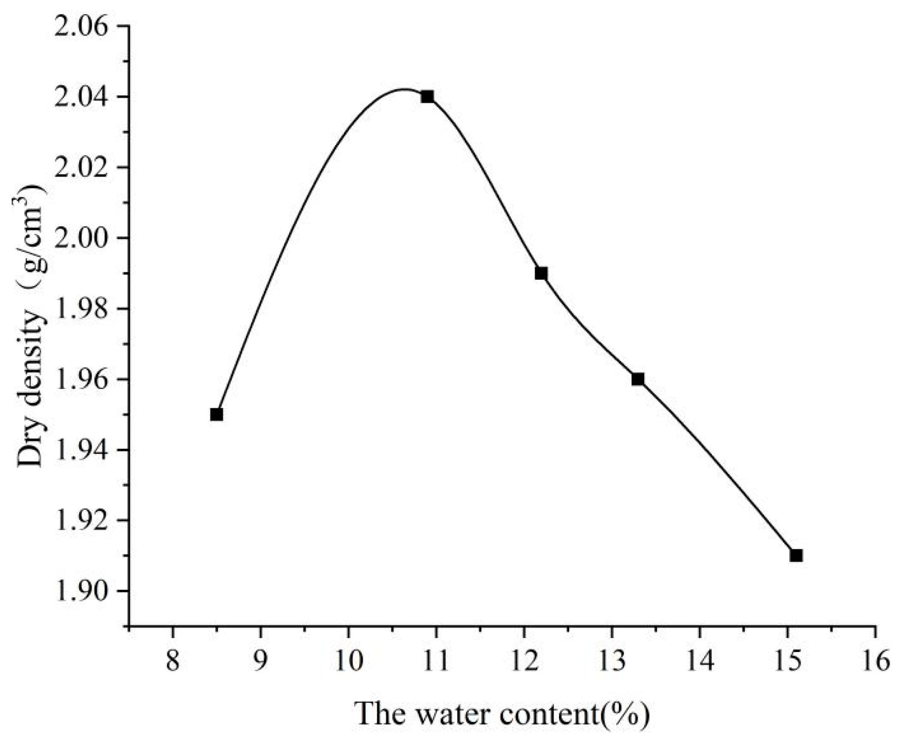
2.2.2. Maximum Dry Density Experiment of Round Gravel Soil

Since the density of the experimental soil sample must be strictly controlled during the remolding process, it is necessary to measure the maximum dry density and the optimum moisture content of the round gravel soil, and the heavy compaction instrument is used for the experiment. During the experiment, take out particles larger than 40 mm and get their percentage P, and then compact the part of round gravel soil smaller than 40 mm. After the experiment, the maximum dry density and the best water content obtained from the experiment need to be corrected (applicable to the content of particles larger than 40 mm is less than 30%). Calculate the dry density of each point according to the experimental results, take the dry density as the ordinate and the water content as the abscissa, and draw the relationship curve between the dry density and the water content. The ordinate and abscissa of the peak point on the curve are the maximum dry density and the best water content, respectively. The results are shown in Table 2.
The dry density and the water content curves are shown in Figure 4, which shows that the dry density increases with moisture content and then decreases. In contrast, the maximum dry unit weight and optimal moisture content correspond to the fitted curve’s top, consistent with the dry density of fine-grained soil [27,28]. Wang et al. [29,30] found that the dry density of gravelly calcareous sand increased with increasing water content when the water content was greater than 8%. Although both are coarse-grained soils, the dry density shows a different variation pattern, mainly due to the fact that when the water content of gravelly calcareous sand exceeds 8%, the capillary suction between soil particles is weakened. Particle movement intensifies while particles’ relative fragmentation rate increases, but it is always smaller than the relative fragmentation rate of dry calcareous gravelly sand, resulting in the increase of dry density with the increase of water content. In comparison, the round gravelly soil has already reached the liquefaction limit when the water content reaches 11%. If the water content increases, the specimen becomes liquefaction, and the dry density decreases.
The results show that the optimum moisture content of round gravel soil is 11%, the maximum dry unit weight is 2.04 g/cm3, and the corresponding wet density is 2.26 g/cm3. Since the maximum dry density cannot be reached in the field for round gravel soil, in order to make the experimental specimens closer to the actual engineering site, the wet density corresponding to 0.87 of the maximum dry density is taken as 1.97 g/cm3 for the indoor direct round gravel soil with reference to a large amount of relevant literature. The soil sample was prepared for the indoor direct shear experiment.

2.3. Experimental Methods and Procedures

2.3.1. Experimental Methods

The soil samples collected in the field were air-dried and sieved in the experiment. The soil material was weighed according to the particle gradation of round gravel soil after scale reduction and mixed evenly after spraying an appropriate amount of water according to the natural moisture content of 13.1%, divided into three parts equally, and loaded into the bogging bucket, enclosing for 24 h. Control the wet density of round gravel soil to 1.97 g/cm3, the sample was loaded and compacted in layers, the inter-layer hair scraping treatment was required, and strictly control the filling density of the sample. For the direct shear experiment of round gravel soil under saturated conditions, after filling samples, water was added to the test chamber to cover the shear box, and the shear test shall be conducted after 24 h saturation. The experimental loading was strain-controlled, and the straight shear test was performed by fast shear, as shown in Figure 5.

2.3.2. Experimental Procedure

(1)
Loading sample: according to the determined density, gradation, and moisture content of the filler, weigh the soil material in three parts, mix and blend, and load into the shear box in layers of compaction, each time loading to 1/3 of the total height of the shear box, until the control height, after completion, level the surface.
(2)
Vertical loading: according to this experiment to determine the load level (low pressure: 100, 200, 300, 400 kPa) using servo motor control loading, stable pressure after observing the vertical displacement and event change curve until the stability standard control in the stability standard control at 0.002 mm/min.
(3)
Horizontal shear: after the soil sample vertical loading stability, according to the same strain rate horizontal shear, the shear rate of 1 mm/min, while observing the experimental machine data acquisition system until the specimen damage. Experiment until the soil sample horizontal shear displacement reaches 15% of the diameter of the specimen when the end of shear.
(4)
The specimen damage determination: when the horizontal stress table readings fall, no longer rise or rise very little, the deformation change is large, that has been shear damage. If none of the above, when the shear deformation reaches 15% of the diameter of the shear box, stop the shear experiment. After the experiment, clear the soil on the shear box, analyze the shear surface characteristics, and take pictures.

2.4. Test Results and Analysis

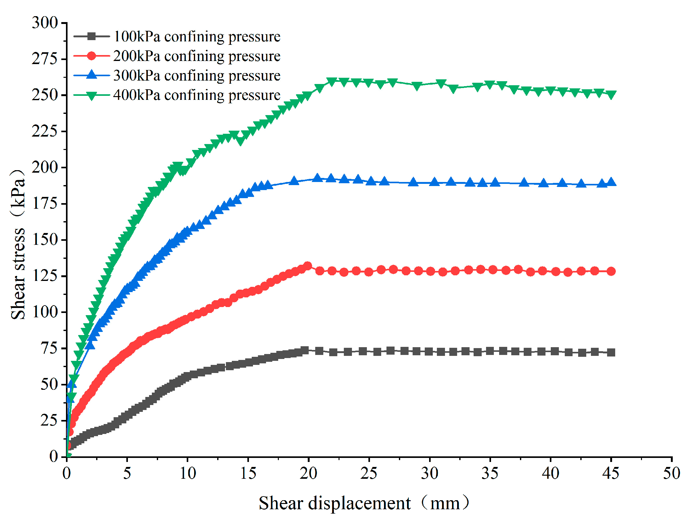
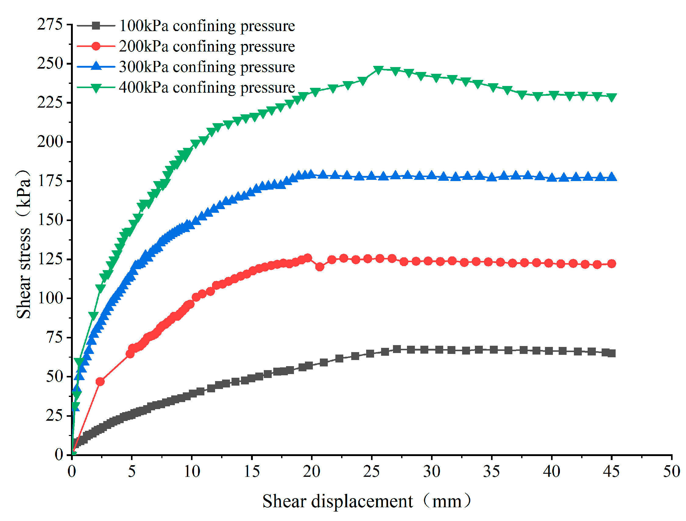
2.4.1. Shear Stress-Shear Displacement Curve Change Characteristics Analysis

Figure 6 shows the round gravel soil’s fast shear stress-shear displacement curves in the natural water content state. As can be seen from the figure, the shear stress of the round gravel soil of the 14th water purification plant of Kunming City increases with the increase of shear displacement and then tends to be stable or decreases to a smaller extent, with the peak shear value appearing between 30% and 45% of the shear displacement. It can be seen that the curve jumps at some points, mainly since the initial density of the sample is small, and the shrinkage is continuous during shearing, resulting in the increase of compactness and strength and the increase of shear stress. Due to large interlocking particles of gravel in the sample, the overturning friction between the large particles of gravel requires a large horizontal thrust as the shearing proceeds, resulting in a rapid rise of shear stress. After the overturning, since the overturning friction resistance between coarse and fine grains is small, the shear stress decreases slightly while the shear plane is still in a tight state, and the shear stress continues to increase until reaching the peak. Low load specimen shear stress with the increase in shear displacement always maintains an increasing trend. With the increase in vertical load, this trend gradually weakened, combined with the end of the experiment shear surface. The difference in the distribution of large particles near the shear plane may cause this. The shear stress is high if there are many large particles in the shear plane.
In order to investigate the difference between the natural and saturated moisture content states of the round gravel soil, direct shear experiments were designed to be conducted under the saturated moisture content conditions of the round gravel soil. The shear displacement-shear stress relationship curve after shearing is shown in Figure 7. As seen in Figure 7, the shear stress of saturated gravel soil increases with the shear displacement and then stabilizes. The shear stress of saturated gravel soil is smaller than that of the natural state compared with the shear stress-shear displacement curve of the natural state. The shear surface morphology of round gravel soil specimens in a saturated water content state has no large particle fragmentation phenomenon. The reason is that the saturated state specimens with high water content, due to the lubricating effect of water molecules and the soil, are looser between the soil, resulting in reduced friction between soil particles; the soil particles directly overturn each other during shear.

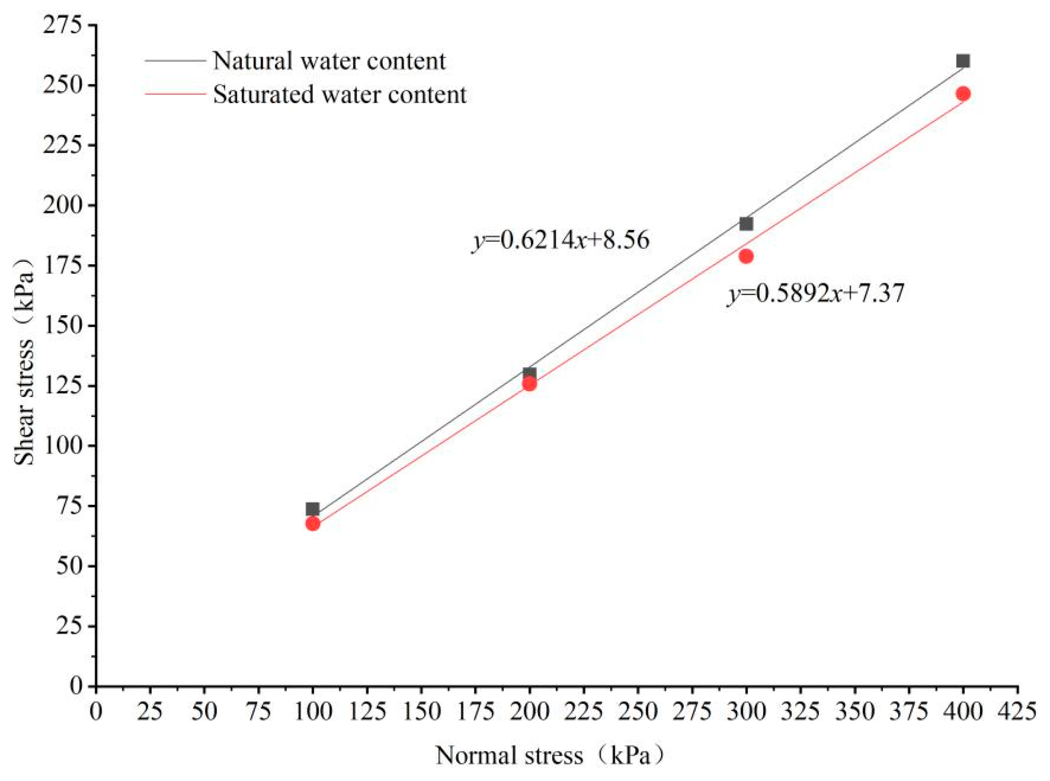
2.4.2. Characterization of Shear Strength Parameters

According to the geotechnical test specification, the peak or stable value on the relationship curve between shear stress and horizontal displacement is taken as the shear strength. When there is no obvious peak, the shear stress at the horizontal displacement reaches 1/15~1/10 specimen diameter and is taken as the shear strength. Therefore, according to Figure 6 and Figure 7, the peak shear stress is taken as the shear strength during this experiment. The relationship between the shear strength and the positive stress is linearly fitted by combining the Moore-Coulomb strength criterion. The results are shown in Figure 8.
From Figure 8, it can be seen that the cohesion and internal friction angle of the saturated moisture content of the round gravel soil are smaller than those of the natural moisture content, which is since the water content of the saturated round gravel soil is larger than that of the natural state. The lubricating effect of the free water on the surface of the soil particles is enhanced, resulting in the weakening of the occlusal force between the particles and the weakening of the frictional effect, and the smaller horizontal thrust can make the soil produce larger shear displacement. The strength parameters of the round gravel soil in the natural and saturated state are shown in Table 3 from Figure 8.

3. Engineering Application Study on Shear Strength Parameters of Round Gravel Soil

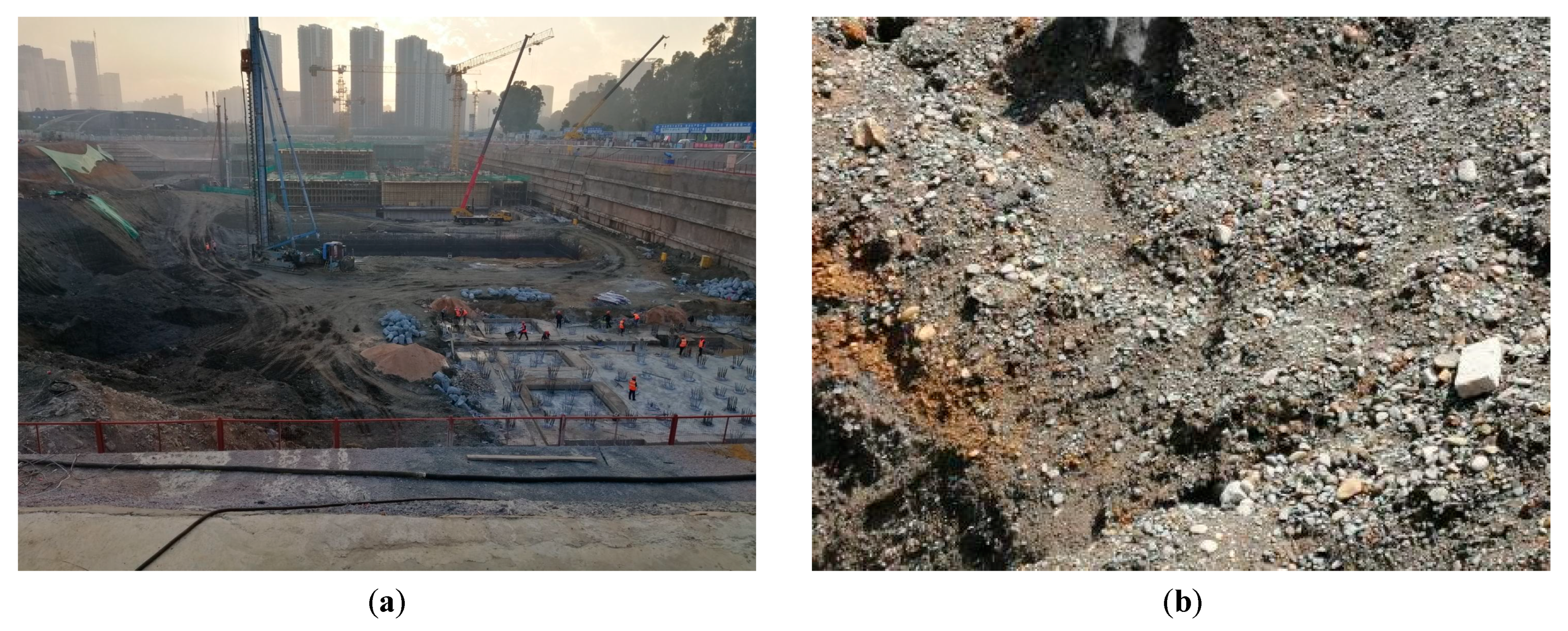
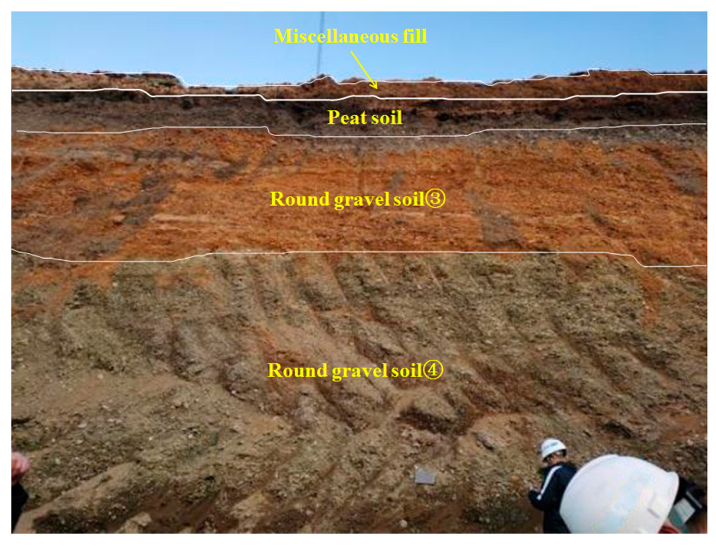
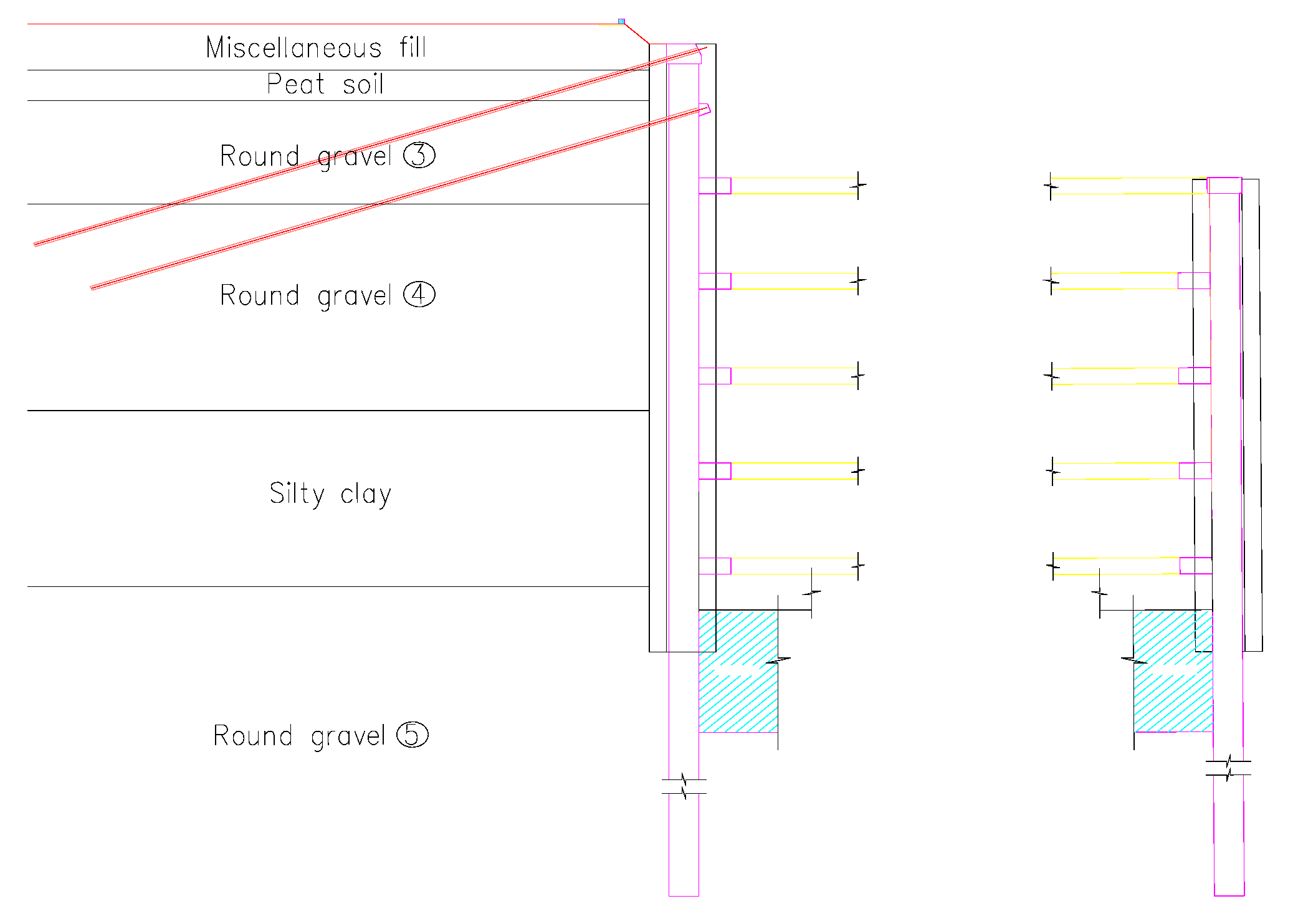
3.1. Project Overview

The construction project of Kunming 14th, Water Purification Plant is a fully buried underground sewage treatment plant located in Panlong District, Kunming City, Yunnan Province, at the northern end of the Kunming Dianchi faulted basin. The shape of the basin is irregular, but generally it is longer from north to south and narrower from east to west, which is consistent with the structural trend. The ground elevation is between 1901.89 and 1907.57 m, and the maximum elevation difference is about 5.68 m. As shown in Figure 9, the stratigraphic structure within the depth of the pit survey mainly consists of the Quaternary artificial accumulation (Q4ml) layer: artificial fill; the Quaternary alluvium (Q4al + pl) layer: clay, round gravel, and powder; and the Quaternary marsh phase sediment (Q4h) layer: peaty soil and organic soil. The gravels are composed of chert, sandstone, and a small amount of basalt and quartz, rounded to subrounded, with good rounding, and filled with a small amount of silt and clay between grains, with poor cementation, and locally produced with thin laminated pebbles. Round gravel ③ has a grain size of 1.0–4.0 cm, a small amount of 5.0–6.0 cm, and a gravel content of 50–70%. Round gravel ④ has a grain size of 1.0–4.0 cm, with a small amount of 5.0–6.0 cm and a gravel content of 50–60%. Round gravel ⑤ grain size 0.5 cm~4.0 cm, a small amount of 5.0~6.0 cm, gravel content about 50~60%. Round gravel ⑥ Grain size 0.5 cm–3.0 cm, a small amount of 4.0–5.0 cm, gravel content about 50–65%. Round gravel ⑦ grain size 0.5 cm~2.5 cm, a small amount of 4.0~6.0 cm, gravel content of about 50~60%. Round gravel ⑧ grain size 0.5~2.0 cm, a small amount of 3.0~4.0 cm, gravel content about 55~65%. Regionally, it belongs to the Jinsha River system and Dianchi basin, and the surface water body is more developed. The groundwater type in the site is mainly upper stagnant water and diving, and the water level burial depth is between 0.8 and 1.5 m.
The pit covers an area of 65,800 m2, and the depth of pit support is 14~33 m. The pit is divided into four sections, one of which includes the intake pump room and aeration and sand sink. The modeling object is the intake pump room, with a design depth of 33 m, plan size of 32 m long and 25 m wide, perimeter length of 114 m, and area of 800 m2. 1200 mm diaphragm wall + reinforced concrete internal bearing and anchor cable support form is used for the enclosure structure. The wall height is 43.75 m and 67.5 m, and the width is 5.10~6.00 m, the length of the single reinforcement cage is 44.25 m and 68 m, and the depth of continuous wall embedded in the subgrade is 22.8~42.1 m according to the geological condition. As Figure 10 and Figure 11 show the section of the pit of the inlet pump room and the internal bearing structure, respectively.

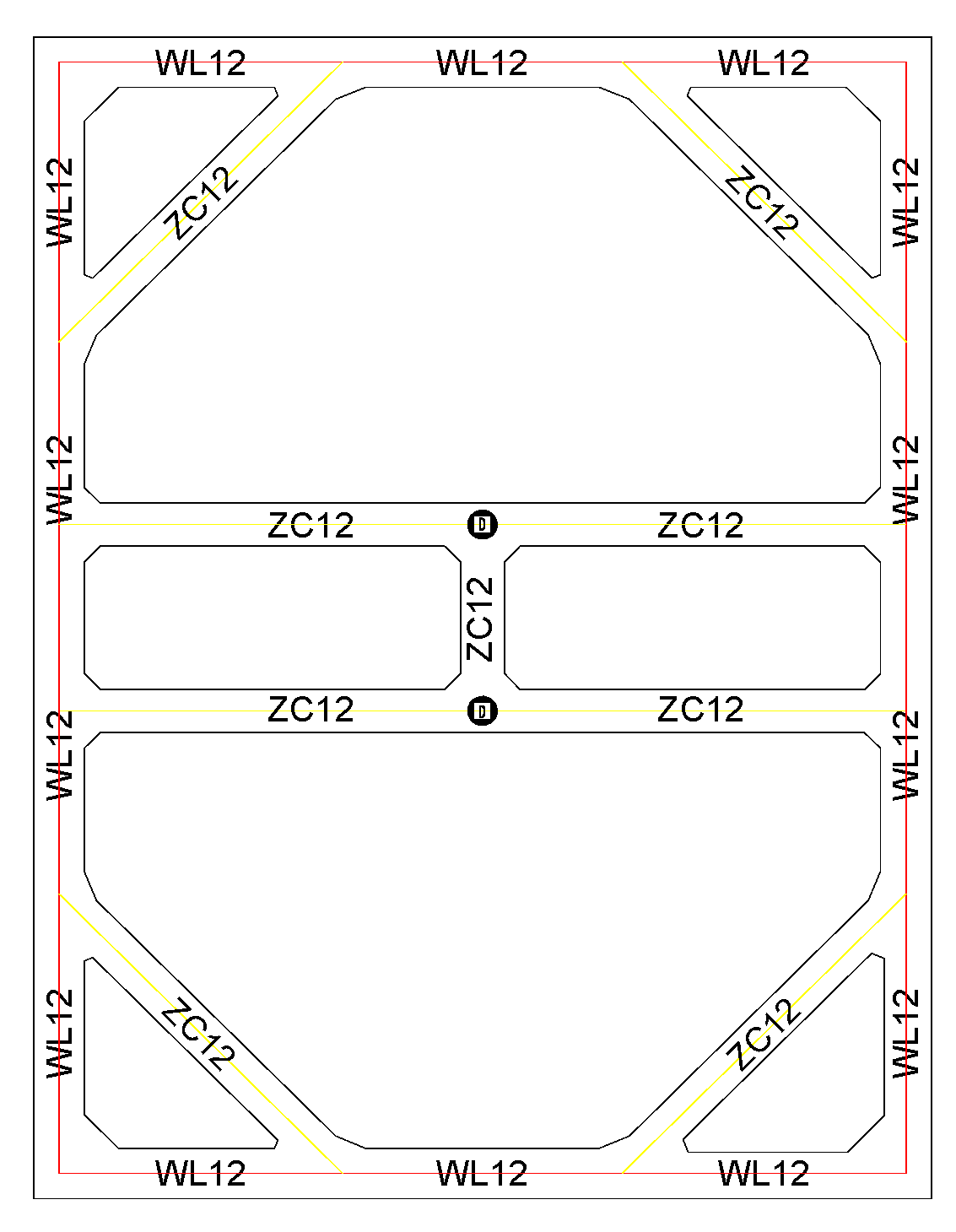
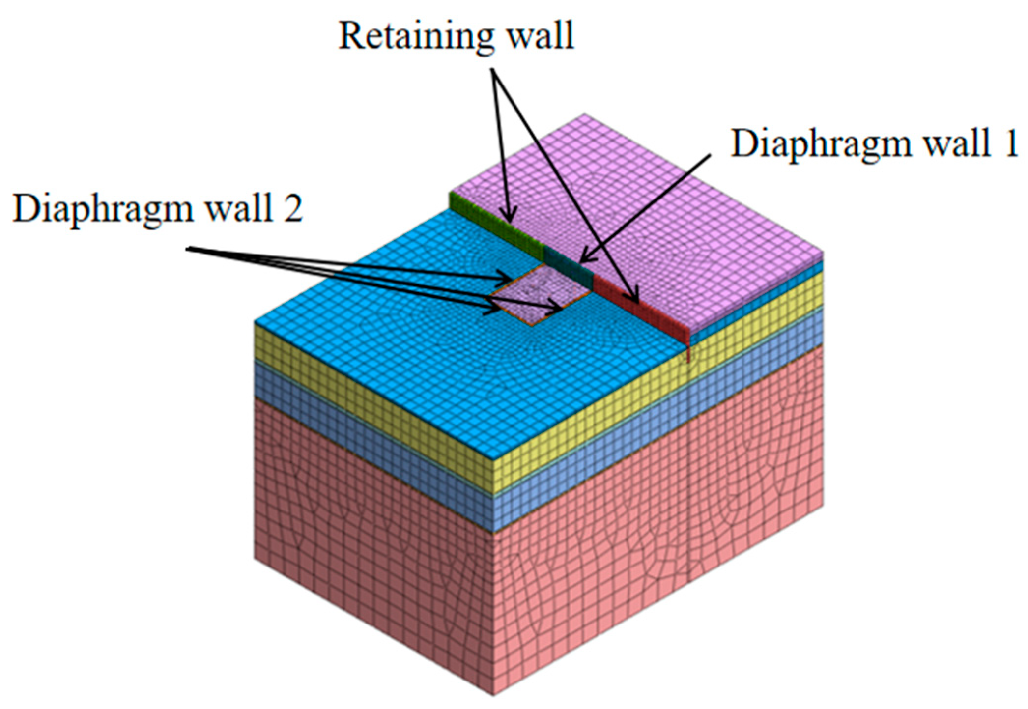
3.2. Pit Modeling and Parameter Selection

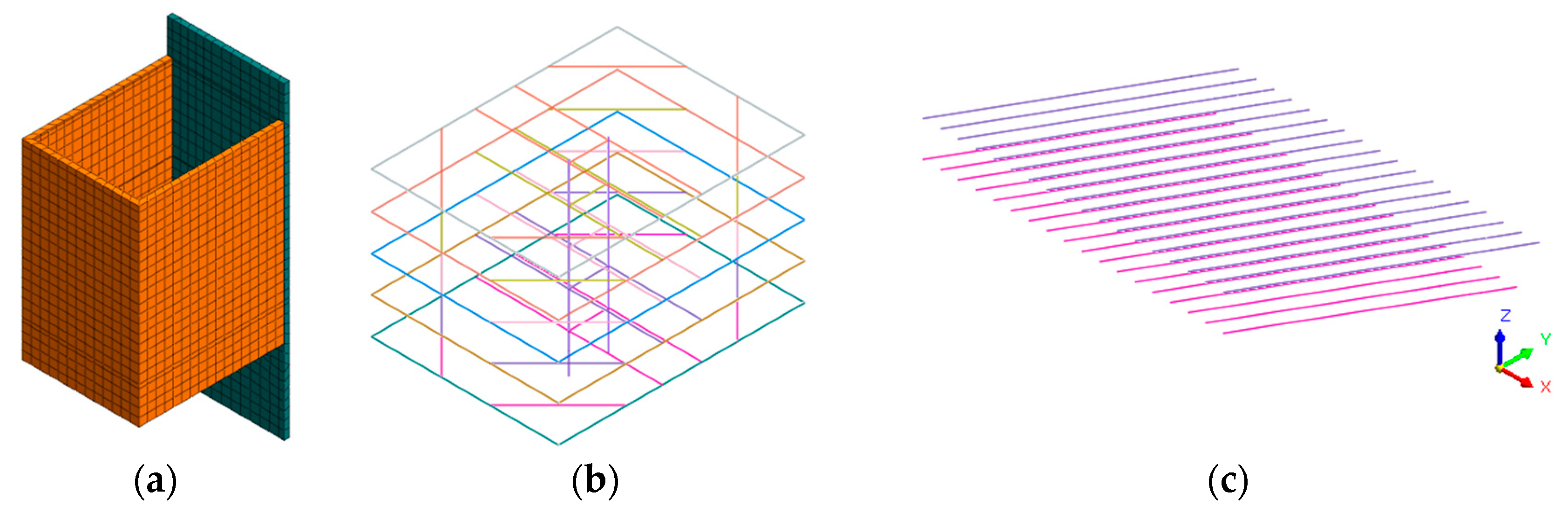
3.2.1. Computational Models

The width of the standard section of the foundation pit is 24.5 m, the length is 32.2 m, and the excavation depth is 29.4 m. the maximum length of the diaphragm wall is 70 m. The minimum length is 44 m. In order to reduce the influence of the simulated boundary conditions on the simulation process, the boundary is taken six times the excavation depth of the foundation pit. The model size is 180 m × 120 m × 120 m. as the construction depth of the diaphragm wall 2 is −8.7 m, the overall Foundation pit excavation to −8.7 m before starting into the pump room pit construction. Therefore, in this simulation pit excavation from −8.7 m to start, diaphragm wall 1 to the boundary to retaining wall simulation, calculation model as shown in Figure 12, simplification will not have a large impact on the accuracy of the calculation and the essence of the calculation. The model grid of the 3D finite element model of the foundation pit is mixed, the total number of cells of the overall foundation pit model is 77,202, and the total number of nodes is 47,899. The calculation uses displacement boundary conditions; in the left and right boundaries of the model, the displacement in the X direction is fixed, and in the front and back boundaries of the model, the displacement in the Y direction is fixed. Moreover, at the bottom of the model, the displacement in three directions is fixed. In the modeling process, the soil and diaphragm wall are simulated by solid units, the internal bearing and lattice columns are simulated by beam units, and implanted trusses simulate the prestressed anchor cables. Figure 13 shows the schematic diagram of the calculation model of the foundation support structure of the intake pump room. As shown in Figure 13, the diaphragm wall, internal bearing, and anchor cable together form the foundation support system. The three arrangements in the calculation model are shown in Figure 10.

3.2.2. Calculation Parameters Selection

Based on the large direct shear experiment of round gravel soil, the cohesion and internal friction angles in the natural and saturated states were determined to be 31.9°, 8.56 kPa, and 30.5°, 7.37 kPa, respectively, and the other soil parameters referred to in the modeling calculations were determined based on the Detailed Geotechnical Investigation Report of the Fourteenth Water Quality Purification Plant of Kunming City and related literature [31,32,33]. Since the support structures such as diaphragm walls, anchor cables, and internal bearings are in an elastic stress state, the soil in the model is an ideal elastoplastic medium. The soil model widely used in actual engineering is the Mohr-Coulomb elastoplastic model. Therefore, the Mohr-Coulomb principal model is used in the calculation. The mechanical calculation parameters of the soil are shown in Table 4, and the structural and mechanical parameters are shown in Table 5.

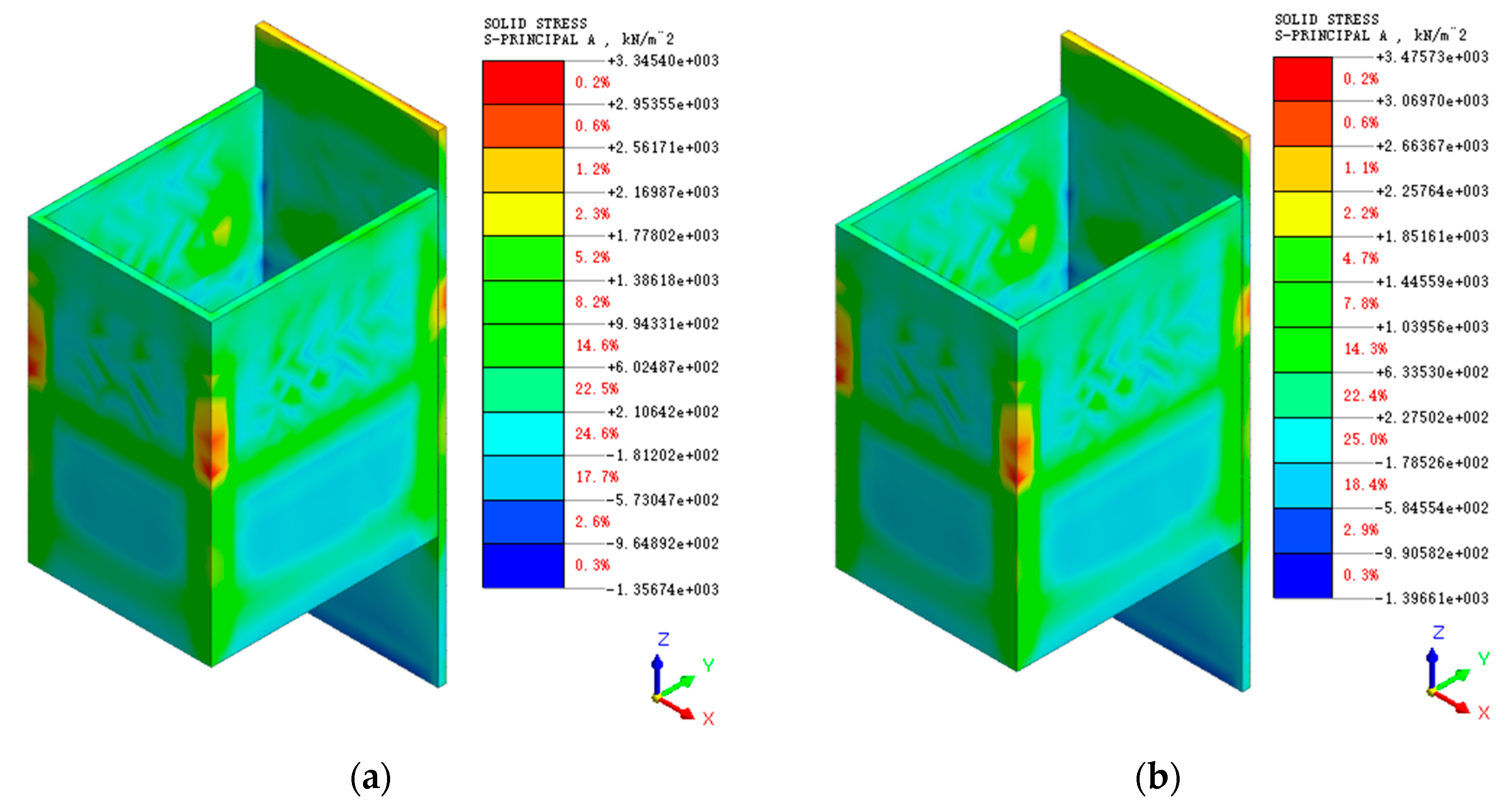
3.3. Results Analysis

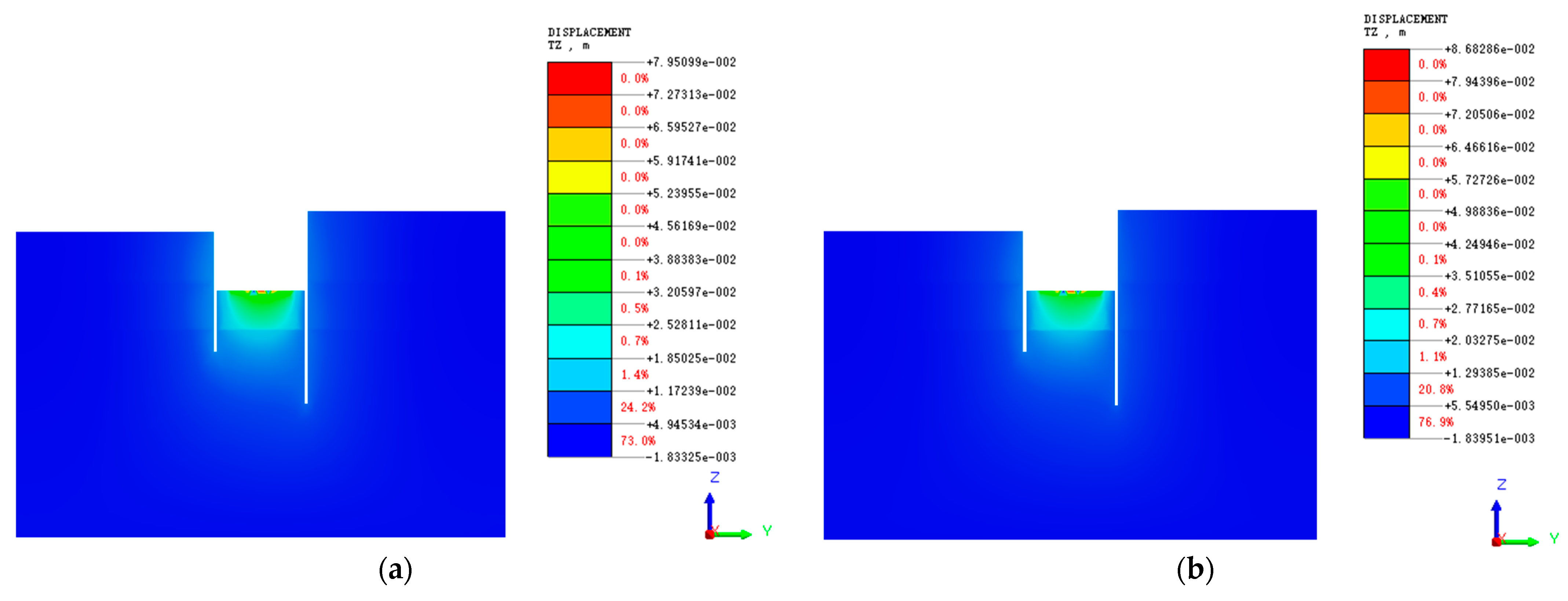
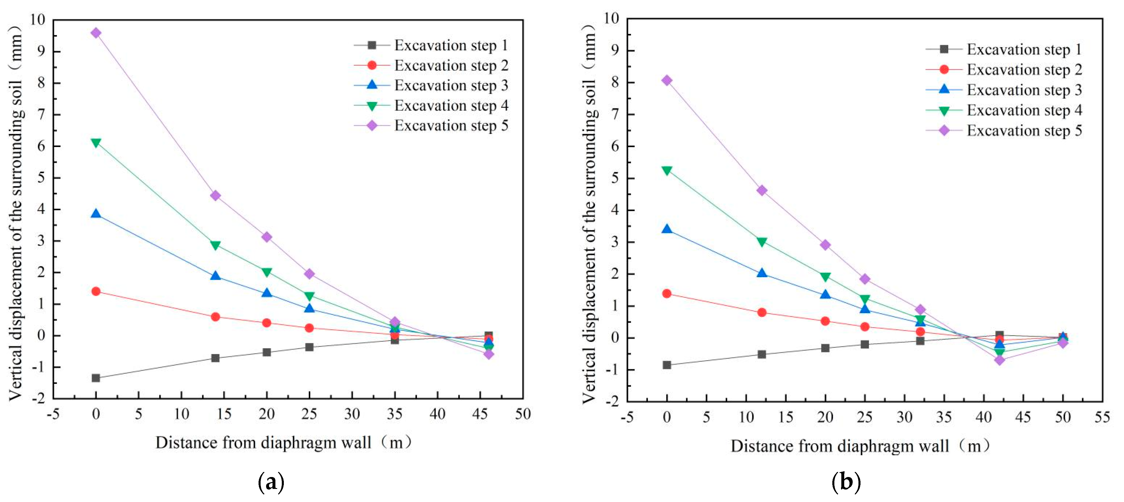
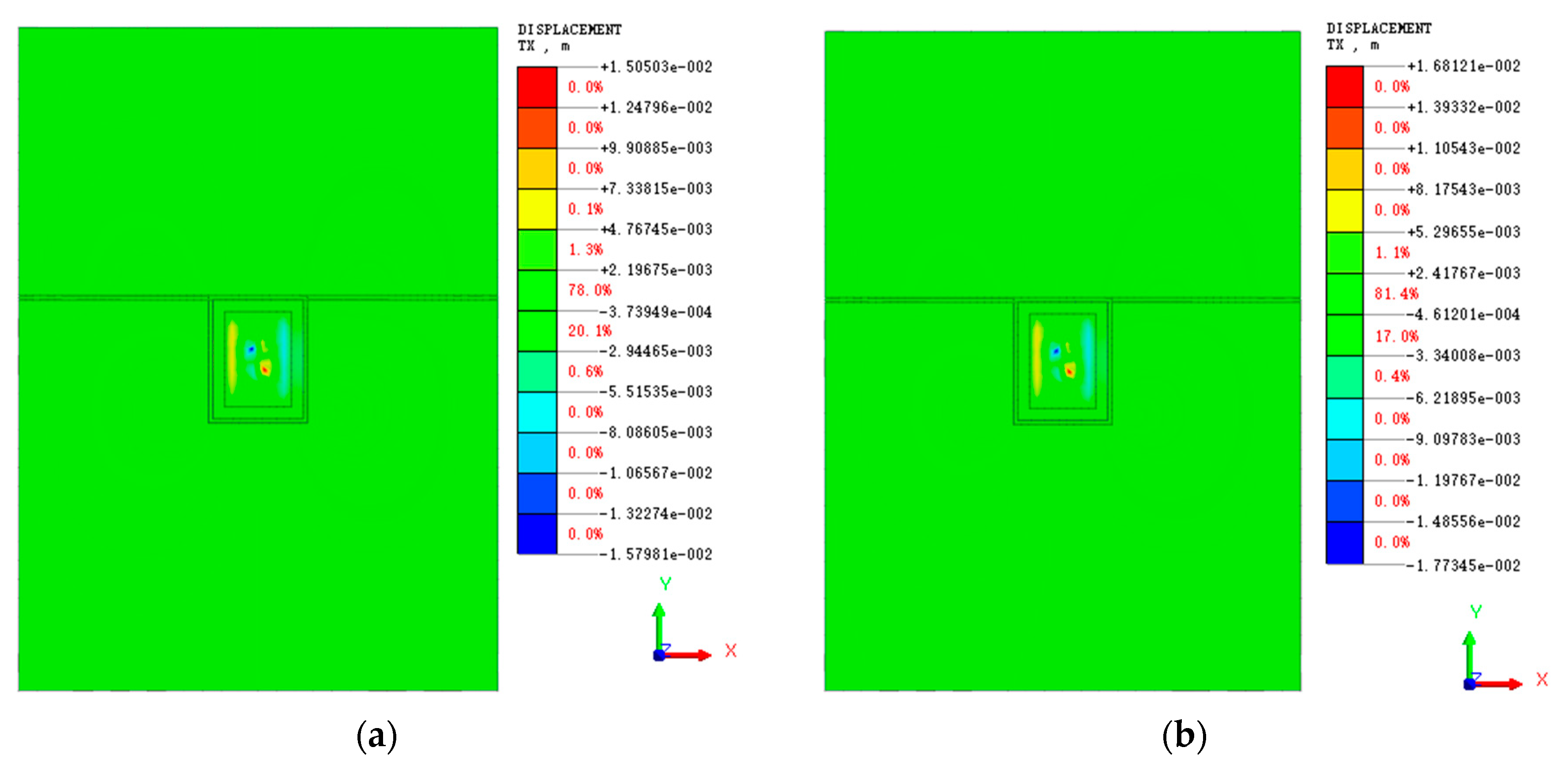
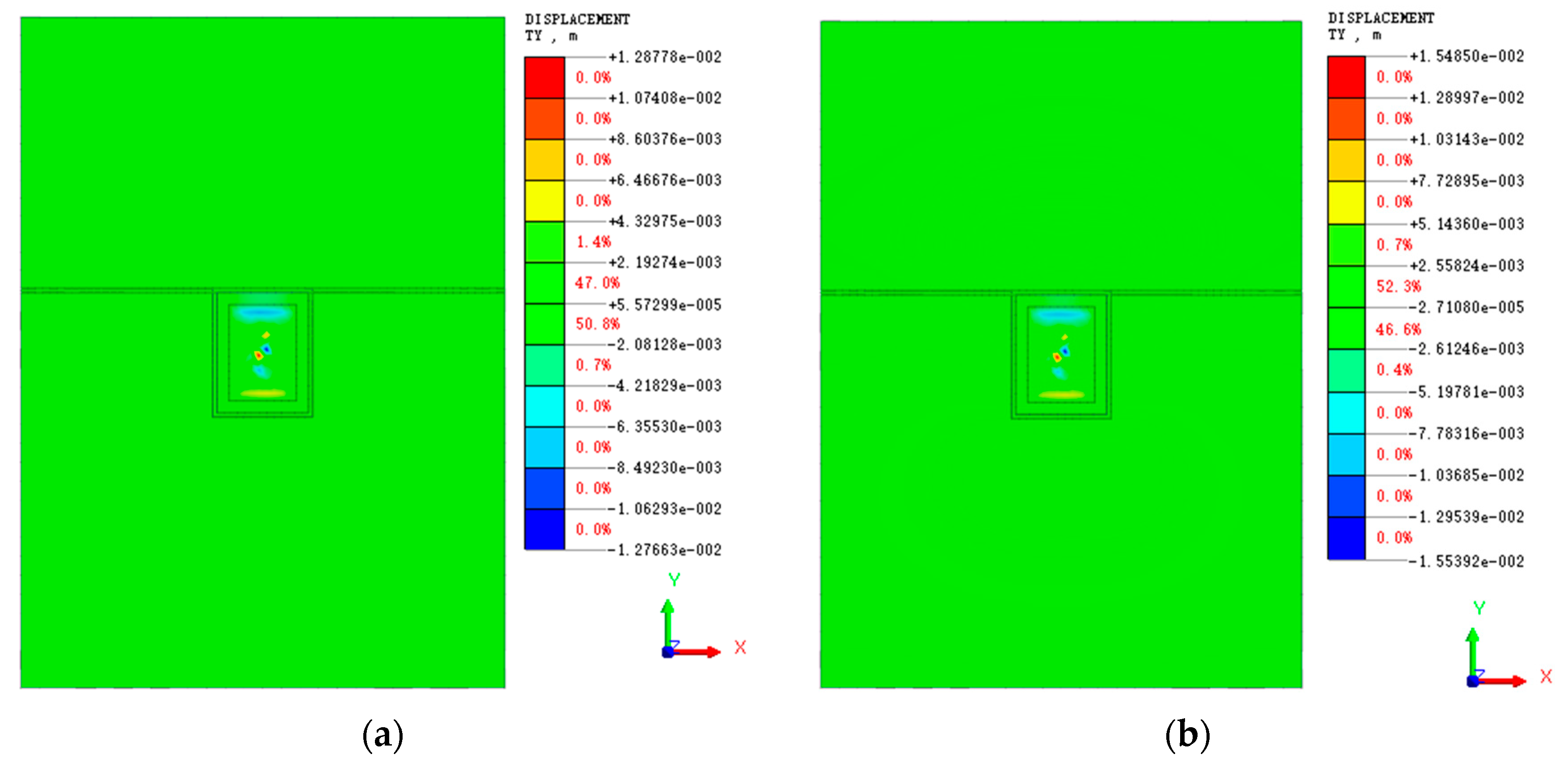
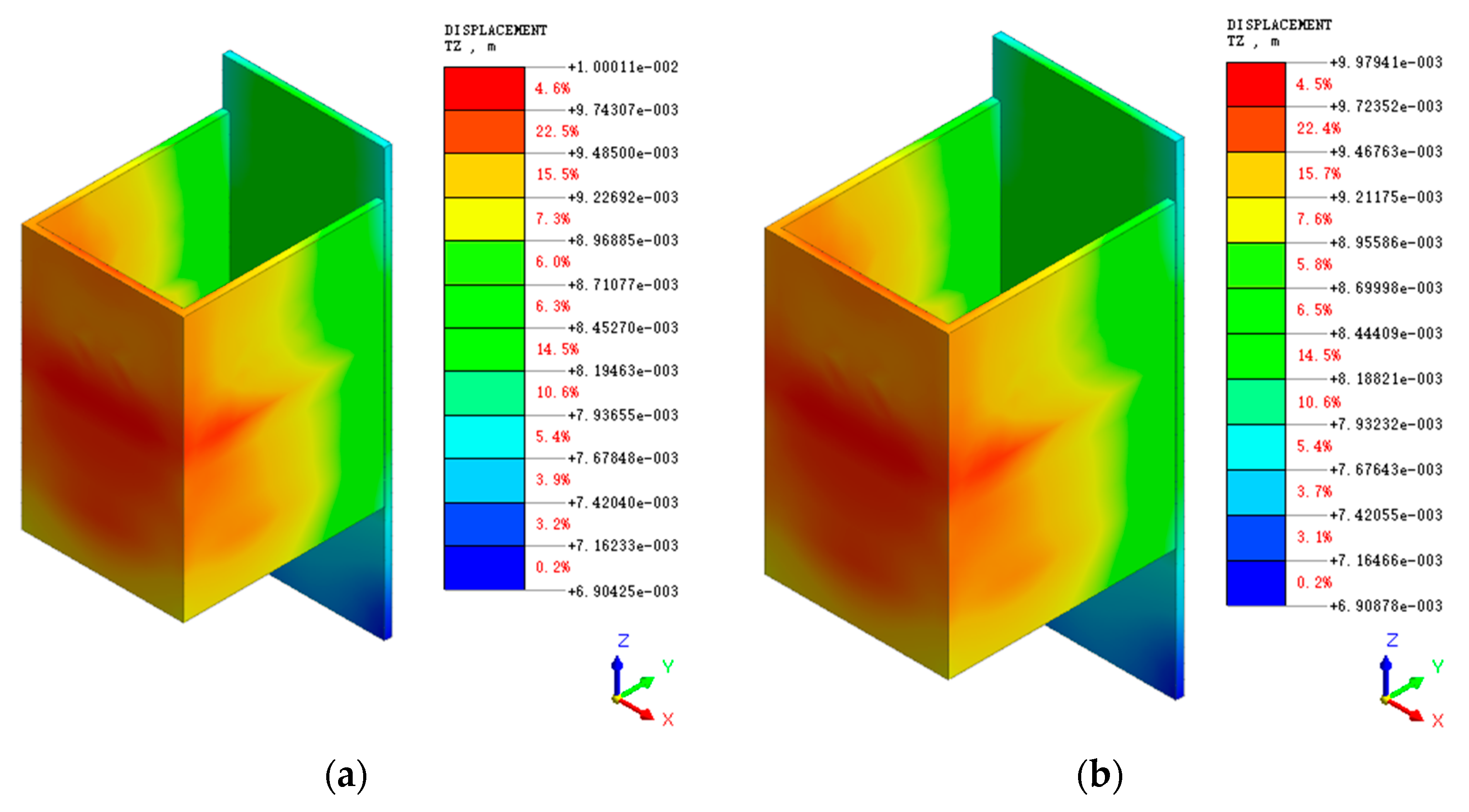
3.3.1. Analysis of the Evolution Law of Foundation Pit and Surrounding Soil Displacement

In order to better analyze the surface settlement around the inlet pump room pit and the uplift of the pit bottom, the vertical displacement of the soil body is analyzed by selecting the short-side midline section of the diaphragm wall. As shown in Figure 14, the soil body is elevated 15 m below the pit bottom. It gradually decreases downward in a semicircle with the center of the pit bottom. The equilateral triangle centered on the lattice column has a small sinkage of 0.5 m from the center to the edge line. The soil in the middle of the two lattice columns has a large uplift. The maximum uplift reaches 8.68 cm under the saturation shear strength parameter and 7.95 cm under the natural shear strength parameter. The difference between the two reaches 7.3 mm, indicating that the shear strength parameter influences the soil’s vertical displacement in excavating the foundation pit. Therefore, the shear strength parameter of the soil needs to be accurately determined in the calculation of the foundation pit design. Otherwise, it will easily lead to the excavation process of the foundation pit and the soil at the bottom of the pit will bulge too much and make the pit unstable. There is no sinking of the soil in a certain range around the excavation of the foundation pit, but there is a slight uplift. However, the uplift value is negligible. The soil outside the 5~15 m range of the diaphragm wall is affected by the excavation and sinks, and the sinking distance of the surrounding soil is close to the maximum settlement distance of 1.83 mm under the two parameters. The displacement is small and will not affect the surrounding buildings and roads.
Since the surface vertical displacement variation pattern under the conditions of two shear strength parameters of round gravel soil is consistent, the displacement variation curve under the conditions of natural shear strength parameters of round gravel soil is selected for analysis in this study, as shown in Figure 15. As can be seen from Figure 15, the soil at the edge of the foundation pit sinks after the end of excavation step 1. With the increased distance from the diaphragm wall, the sinking of the surrounding surface gradually decreases. The surrounding surface starts to rise outside the range of 40 m from the diaphragm wall. Furthermore, the soil around the foundation pit within 40 m is uplifted in the second step of excavation to the end. With the increase of excavation depth, the soil uplift around the foundation pit gradually increases. From the end of excavation step 2 to the end of the excavation, the uplift of the surrounding surface soil gradually decreases with the increase of distance from the diaphragm wall, and the decrease rate gradually increases with the increase of excavation depth. The main reason for the bulging of the soil around the foundation pit is that the foundation pit is excavated deeper, and the self-weight of the original soil is unloaded rapidly, so the bulging of the foundation is larger and drives the bulging of the surrounding surface soil.
Figure 16 and Figure 17 show the displacement clouds of the surface and the soil at the bottom of the pit in X and Y directions around the end of the foundation pit excavation under natural and saturated shear strength parameters of round gravel soil, respectively. From Figure 16, it can be seen that after the end of the pit excavation, the soil’s horizontal displacement at the pit bottom is locally larger, which is located on both sides of the lattice column, respectively. The maximum horizontal displacement is 15.7 mm, mainly due to the combined effect of the lattice column and excavation unloading. Affected by the reinforcement area of the pit bottom, the horizontal displacement of the pit bottom soil is slightly larger at the edge of the long side but smaller than the two sides of the lattice column. The horizontal displacement of the soil body under the saturated shear strength parameter of round gravel soil is slightly larger than that under natural conditions; the maximum is 17.7 mm.
As shown in Figure 17, the maximum horizontal displacement of the subsoil of the foundation pit is located in the middle of the lattice column, and the horizontal displacement in the Y direction is slightly smaller than that in the X direction, which is mainly affected by the size and shape of the foundation pit. The horizontal displacement of the surrounding ground surface is very small and will not affect the surrounding buildings.
The horizontal displacement change curve under the natural shear strength parameter of round gravel soil is selected for analysis in this study, as shown in Figure 18. The midpoint of the foundation pit edge on the short side of diaphragm wall 1 and diaphragm wall 2 is taken as the monitoring point. As seen from the figure, during the first two excavation steps, the soil body on the side of diaphragm wall 1 is displaced into the pit. The horizontal displacement gradually decreases with the increase of burial depth. As the excavation progresses, the horizontal displacement gradually changes to the displacement outside the pit. Since the pit excavation unloads, the lower soil body extrudes the diaphragm wall to the pit so that the diaphragm wall above the initial excavation surface shows a trend of outward displacement, and the soil body is then displaced. Diaphragm wall 2 is displaced to the foundation pit’s inner side, with the burial depth increasing gradually; the curve at −25 m appears to turn, mainly by the influence of stratigraphic changes.

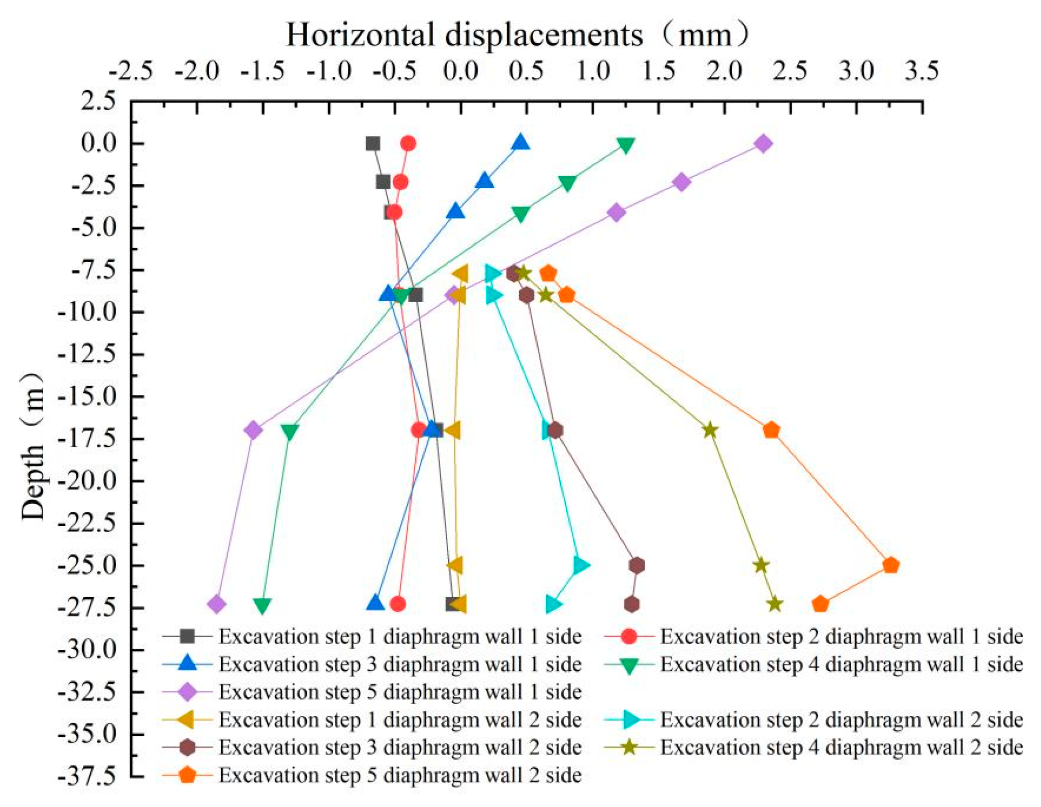
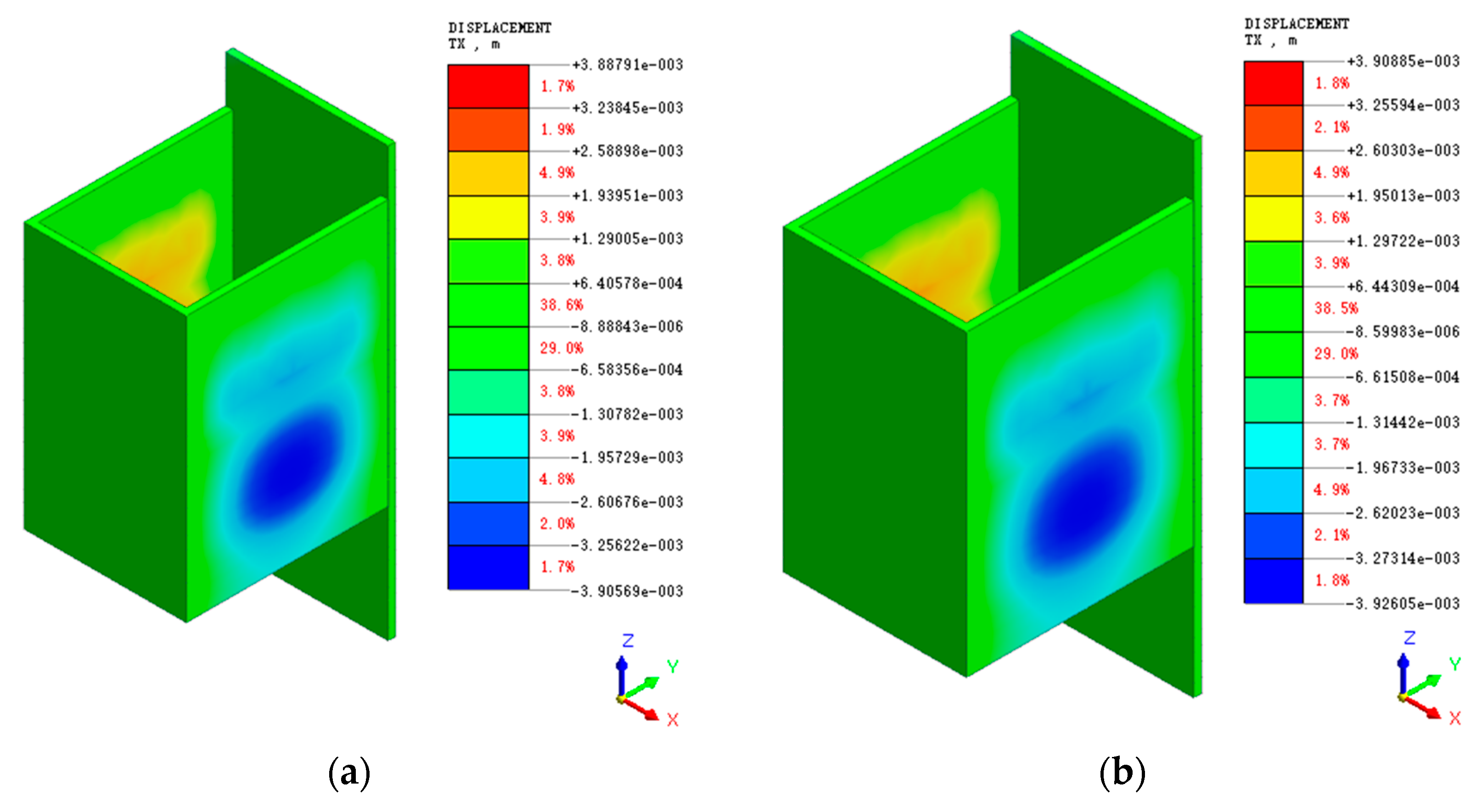
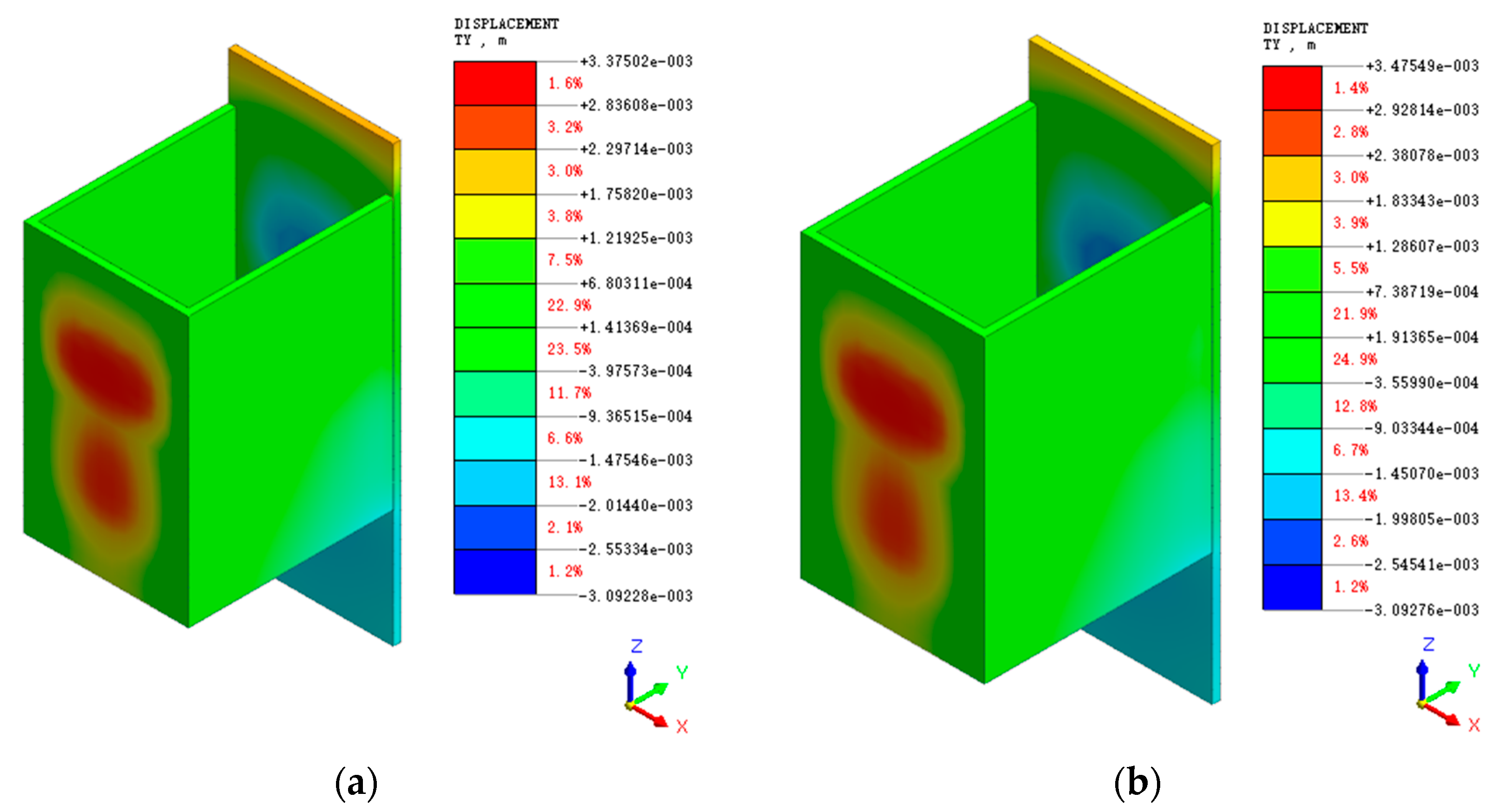
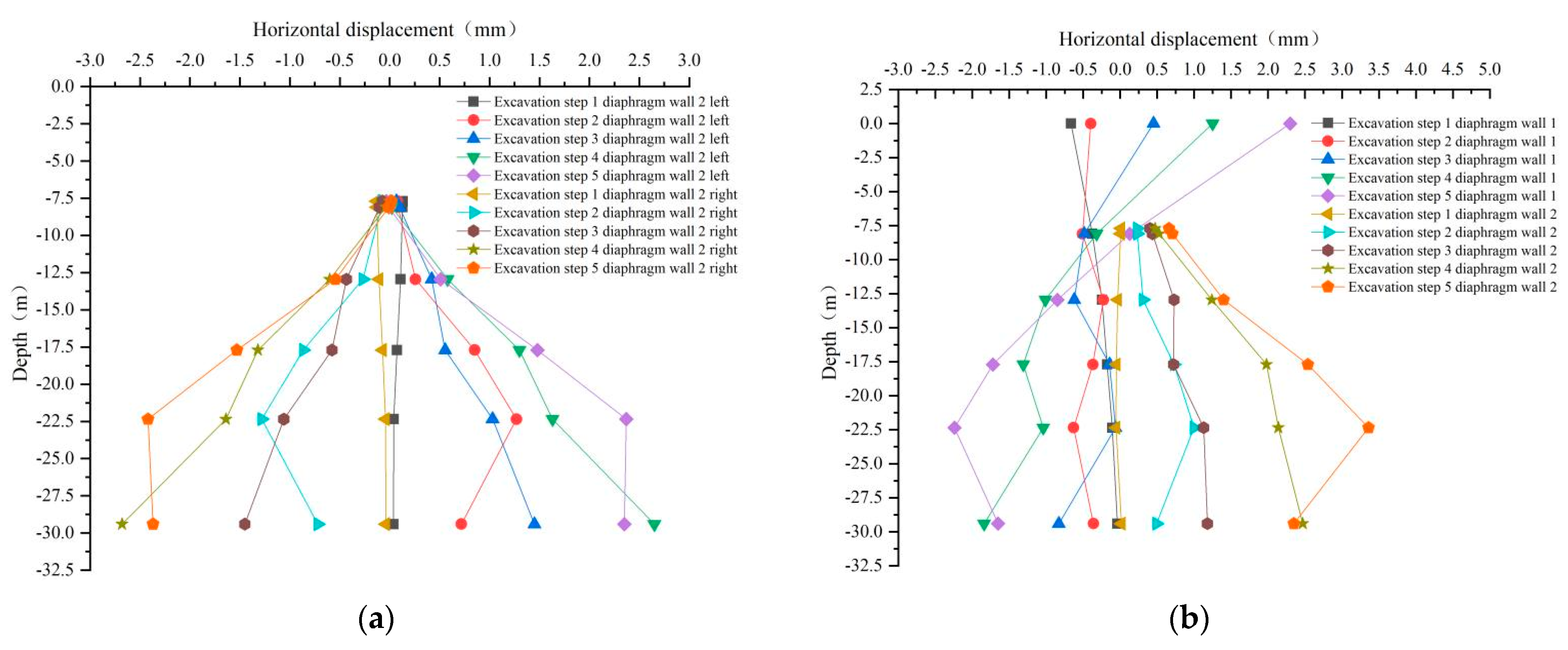
3.3.2. Analysis of Displacement Variation Law of Diaphragm Wall

The excavation process of the foundation pit will change the equilibrium state of the original soil, and the geotechnical body tends to an unstable state from the stable state in its natural state. As the main support structure, the underground diaphragm bears the role of water interception, seepage control, load bearing, and earth retaining and has a significant impact on maintaining the stability of the foundation pit. Excessive deformation of the diaphragm wall may cause wall damage or pit collapse. Therefore, the diaphragm wall displacement must be controlled within the specification requirements. As shown in Figure 19 and Figure 20, the horizontal displacements of the diaphragm wall in the X and Y directions are shown. It can be seen from Figure 19 that when the round gravel stratum is in a state of natural and saturated moisture content, its shear strength parameters have little influence on the horizontal displacement of the diaphragm wall during the excavation of the foundation pit. Under the two-parameter conditions, the horizontal displacement of the diaphragm wall in the X direction is larger in the area below −29.4 m on the long side of the diaphragm wall. Under saturated conditions, the maximum horizontal displacement of the diaphragm wall in the X direction is 3.92 mm, which is far less than the standard warning value.
As shown in Figure 20, the horizontal displacement of the diaphragm wall along the Y-direction is larger in the range of the third inner support to the fifth inner support on the short side and the area below the pit bottom, with a mushroom-shaped distribution pattern. The maximum horizontal displacement in the Y-direction under the two parameters is 0.1 mm different, and it is also larger under the saturated condition, with a maximum displacement of 3.48 mm. it can be seen that the horizontal displacement under the two round gravel soil. The horizontal displacement under the shear strength parameter is close, and the displacement values are small and within the specification warning range, which indicates that the diaphragm wall better supports the foundation pit of the intake pump room.
Select the midpoint of four diaphragm walls for analysis. Figure 21 shows the horizontal displacement curve of the diaphragm wall in X and Y under natural shear strength parameters of round gravel soil. As shown in Figure 21a, during the foundation pit excavation, the horizontal displacement of the long sides of diaphragm wall 2 at different burial depths is symmetrically distributed. Since the excavation depth of the first layer is shallow in the simulation process, the impact on the deep diaphragm wall is small, and the displacement decreases with the increase of the burial depth. During the excavation of the second layer to the fifth layer, it can be seen that the horizontal displacement of the diaphragm wall at the buried depth of 22.5 m has a big change trend. After excavating the second layer, the horizontal displacement of the diaphragm wall suddenly decreases from the buried depth of 22.5 m to the bottom of the pit. In contrast, the excavation of the third layer to the fifth layer continues to maintain an increasing or stable change trend, mainly due to each layer’s excavation depth and the stratum’s influence. From Figure 21b, it can be seen that the horizontal displacement of the top of wall 1 of the diaphragm wall gradually moves out of the pit during the excavation process, mainly due to the effect of the anchor cable in tension and the change of soil pressure behind the wall. It can be seen that with the increase of excavation depth, the horizontal displacement of the diaphragm wall gradually increases.
Figure 22 shows the vertical displacement cloud of the diaphragm wall. As can be seen from the figure, the closer to the short side of the diaphragm wall 2, the greater the vertical displacement. The maximum vertical displacement is located in the wall near the fifth interior bearing on the short side of the diaphragm wall 2, with a maximum vertical displacement of 10 mm. It is larger under natural moisture content and shear strength parameter of round gravel soil, but the difference is only 0.1 mm. The top of the diaphragm wall in the foundation pit has a vertical displacement monitoring alarm value of 10–20 mm. However, the results show that the displacement of the top of the wall does not reach the alarm value, which shows that the diaphragm wall is stable.

3.3.3. Analysis of Displacement Variation Law of Diaphragm Wall

The diaphragm wall is a structure used to block the soil’s lateral pressure on the pit’s side wall, maintain the pit wall’s stability, and ensure the shape of the pit excavation. Its stability is related to the smooth construction of the pit project and the safety of nearby buildings. If the pile structure is damaged or overstressed, it will affect the completion of the pit project and even threaten the safety of the engineering staff. Figure 23 and Figure 24 show the maximum and minimum principal stresses of the diaphragm wall under the above two parameters, respectively. As can be seen from Figure 23, the minimum principal stresses in the diaphragm wall are mainly tensile stresses, and stress concentrations occur at the corners of the diaphragm wall between the third and fifth interior bearing. It can be seen that the inner side of the diaphragm wall is subject to compressive stress, the outer side of the wall is subject to tensile stress, and the tensile stress outside the wall is three times the compressive stress inside the wall. The maximum value of the minimum principal stress is 3.48 MPa. As shown in Figure 24, the maximum principal stress in the diaphragm wall is mainly compressive. The maximum compressive stress is located at the corner of two sides of the diaphragm wall between the third and fifth interior bearing. The compressive stress here is relatively concentrated, with a maximum of 6.1 MPa, which is 0.2 MPa higher than the calculated value under the natural shear strength parameter of round gravel soil. The main stress of the diaphragm wall has an obvious boundary at a depth of the foundation pit bottom, mainly since the excavation of the foundation pit leads to the redistribution of the soil stress behind the wall. However, the stress is small, indicating that the diaphragm wall has a good supporting effect and that the foundation pit is stable.

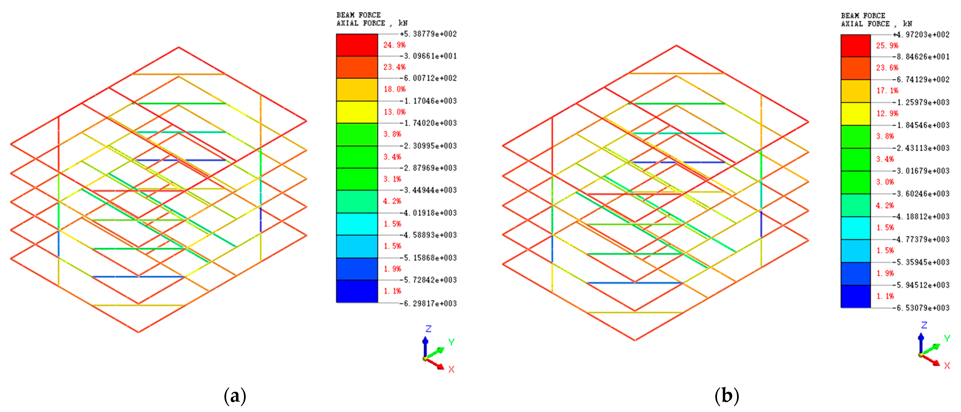
3.3.4. Analysis of the Variation Law of Interior Bearing Axial Force

As one of the main support structures of the intake pump room pit, the internal support bears the role of dispersing the force deformation of the underground diaphragm wall, and its force deformation significantly impacts the pit’s stability. Figure 25 shows the axial force diagram of the interior bearing after the end of the pit excavation under the above two shear strength parameters. Figure 25 shows that the axial force of the diagonal brace in the fourth interior bearing is larger due to the large horizontal displacement of the diaphragm wall at that place after the excavation of the foundation pit is finished. As the excavation depth gradually increased, the maximum value of the interior bearing axial force gradually moved down to the fourth interior bearing since the horizontal displacement of the diaphragm wall gradually moved down to the fourth interior bearing. Under the natural shear strength parameter condition, the maximum axial force of the interior bearing from the first excavation to the bottom of the pit is 0.15 MN, 0.59 MN, 1.66 MN, 2.74 MN, 6.3 MN. The saturated shear strength parameters of round gravel soils under the maximum axial force of interior bearing are 0.15 MN, 0.65 MN, 1.85 MN, 2.95 MN, 6.53 MN. It can be seen that the maximum axial force of interior bearing axial force of the first four layers of soil excavation is small. The axial force of the interior bearing after excavating the last layer changes more. However, it is within the specification design range, indicating that the interior bearing has a good effect.

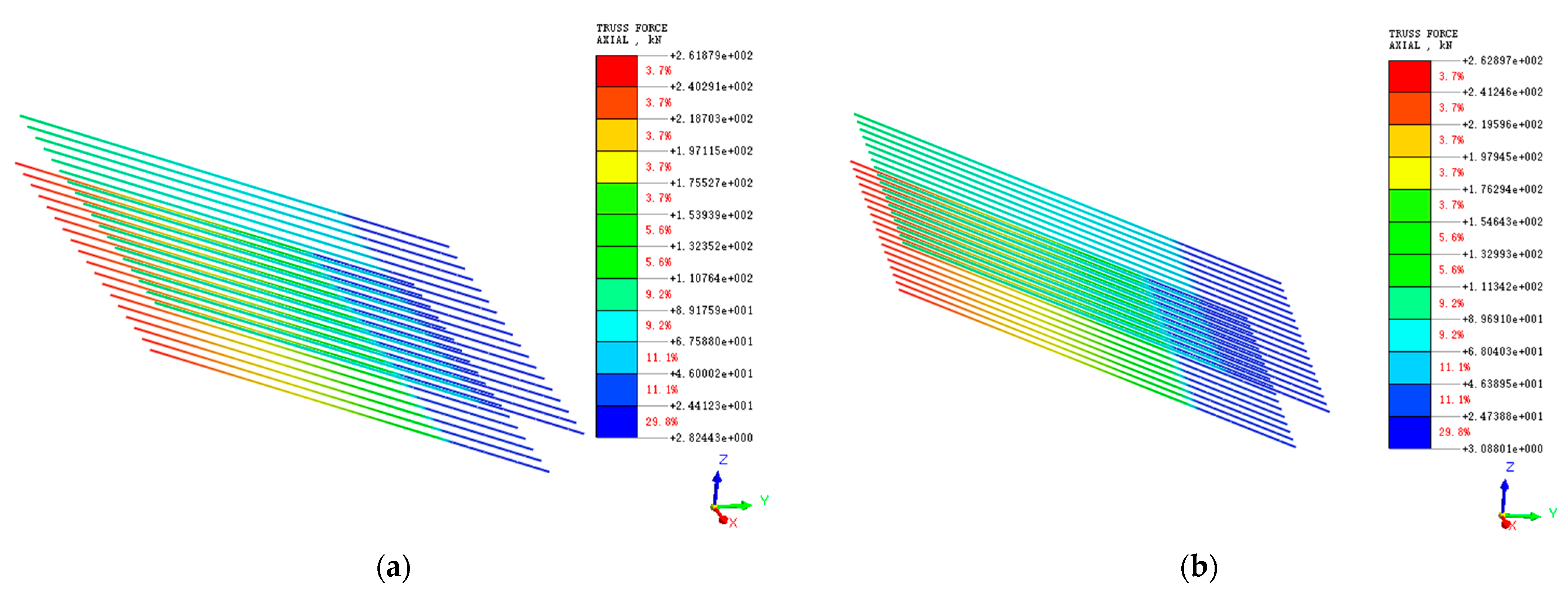
3.3.5. Anchor Cable Axial Force Variation Characteristics Analysis

The anchor cable can transfer the earth pressure on the support pile to the deep soil through the anchor cable’s axial force, so the analysis of the axial force of the anchor cable is important for analyzing the foundation deformation. Figure 26 shows the axial force of prestressed anchor cable under natural and saturated shear strength parameters of round gravel soil. The maximum value of the anchor force is 262.9 kN in the free section of the second row of anchor ropes under saturated conditions and 261.9 kN under natural conditions, and the anchor force in the anchor section is gradually dispersed to the soil around the anchor end by the force transfer of mortar. Hence, the anchor force in the anchor section is smaller. Under the natural shear strength parameter condition, the maximum change of anchor cable axial force during excavation is 257 kN, 258 kN, 259 kN, 260 kN, 262 kN, and under the condition of saturation, the shear strength parameter is 258 kN, 259 kN, 260 kN, 261 kN, 263 kN. The reason is that this simulation mainly starts from the top of the wall of diaphragm wall 2, and the prestressed anchor cable only exists in diaphragm wall 1, which is higher than the simulation depth of the pit. Hence, the excavation simulation has little effect on the anchor cable force.

4. Conclusions

In this paper, based on a comprehensive analysis of the site geological conditions, the shear strength characteristics of round gravel soils and their parameter variation laws were analyzed by reshaping the soil samples retrieved from the site and conducting large-scale direct shear experiments on round gravel soils with natural and saturated moisture content. The research results were applied to the numerical simulation of foundation excavation to obtain the following conclusions.
(1)
The shear strength characteristics of plateau alluvial-lacustrine alluvial round gravel soil under different water content conditions are studied and analyzed through large-scale direct shear tests. Under different water content conditions, the variation law of shear stress-shear displacement of round gravel soil is slightly different. At low water content, with the increase of shear displacement, the particles of round gravel soil are sheared, and the shear surface contacts closely until shear failure, and the soil strength slightly increase. However, the shear resistance curve of round gravel soil with high water content gradually weakened with the increasing confining pressure.
(2)
Large-scale direct shear experiments of round gravel soil show that the cohesion of round gravel soil in the natural state is 8.56 kPa, and the angle of internal friction is 31.9°. In the saturated state, the cohesion of round gravel soil is 7.37 kPa, and the angle of internal friction is 30.5°. With the increased water content, the round gravel soil’s cohesive force and internal friction angle decrease significantly.
(3)
The numerical simulation results of foundation pit excavation show that after the completion of construction, the pit bottom is subject to the joint influence of the reinforcement area and lattice columns. There is a large uplift, and the surrounding surface soil also shows a bulge within a certain range. Hence, further strengthening the monitoring and reinforcement of the surrounding structures is necessary. The stress deformation of the supporting structure is small, far less than the design value. With the increase of the conglomerate soil’s internal friction angle and cohesion, the foundation support and soil deformation decreased, indicating that increasing the shear strength parameter of the conglomerate soil can effectively reduce the foundation deformation. The construction can be carried out by selecting conglomerate strata with different water content in practical engineering to achieve, reduce the project cost and improve the project economy.

Author Contributions

Conceptualization, Z.K. and Y.G.; software, Z.K.; formal analysis, Z.K.; investigation, Z.K.; resources, S.M. and W.Z.; writing—original draft preparation, Z.K.; writing—review and editing, Z.K., S.M., W.Z. and Y.G.; visualization, Z.K.; supervision, Y.G.; project administration, Y.G.; funding acquisition, S.M. and Y.G. All authors have read and agreed to the published version of the manuscript.

Funding

This research was funded by the scientific research fund project of Yunnan Provincial Department of Education, China (No. 2022J0065); key projects of analysis and testing fund of Kunming University of science and technology, China (No. 2021T20200145); China Postdoctoral Science Foundation Project (No. 2017M620433); General projects of Yunnan Fundamental Research Projects (No. 2018FB075); key technology research and pilot test of underground coal gasification, a major scientific and technological research project of CNPC (No. 2019e-25).

Data Availability Statement

The data involved in this study are given in full in the paper.

Conflicts of Interest

The authors declare no conflict of interest.

References

  1. Tan, F.; Wu, S.; Huang, Z.F.; Chen, Z. Discussion on ground bearing capacity of the sandy pebble in the foundation of tall buildings in Chengdu area. Build. Struct. 2013, 43, 30–32, 83. [Google Scholar]
  2. Hou, L.J.; Chen, X.C.; Chen, H.; Cui, C.L. Research on models of surface wave velocity method for determining bearing capacity of cobble soil foundation. Rock Soil Mech. 2008, 29, 2572–2576. [Google Scholar]
  3. Soleimani, S.; Jiao, P.; Rajaei, S.; Forsati, R. A new approach for prediction of collapse settlement of sandy gravel soils. Eng Comput. 2018, 34, 15–24. [Google Scholar] [CrossRef]
  4. Rücknagel, J.; Götze, P.; Hofmann, B.; Christen, O.; Marschall, K. The influence of soil gravel content on compaction behaviour and pre-compression stress. Geoderma 2013, 209, 226–232. [Google Scholar] [CrossRef] [Green Version]
  5. Ghanizadeh, A.R.; Delaram, A.; Fakharian, P.; Armaghani, D.J. Developing Predictive Models of Collapse Settlement and Coefficient of Stress Release of Sandy-Gravel Soil via Evolutionary Polynomial Regression. Appl. Sci. 2022, 12, 9986. [Google Scholar] [CrossRef]
  6. Jiang, J.C. Research on strong dewatering technology for deep foundation excavation in Kunming round gravel stratum. Constr. Technol. 2012, 41, 107–111. [Google Scholar]
  7. Sun, T.; Chen, G.X.; Wang, B.H.; Li, X.J. Experimental research of effect of granule shape on shear modulus and damping ratio of gravel. Chin. J. Rock Mech. Eng. 2014, 33, 4211–4217. [Google Scholar]
  8. Wang, Y.X.; Shao, S.J.; Wang, Z. Experimental study on mechanical behaviors and particle breakage of sandy gravel. Chin. J. Rock Mech. Eng. 2020, 39, 1287–1296. [Google Scholar]
  9. Hara, T.; Kokusho, T.; Hiraoka, R. Undrained strength of gravelly soils with different particle gradations. Mouth 2004, 277, 1920. [Google Scholar]
  10. Kuenza, K.; Towhata, I.; Orense, R.P.; Wassan, T.H. Undrained torsional shear tests on gravelly soils. Landslides 2004, 1, 185–194. [Google Scholar] [CrossRef]
  11. Rollins, K.M.; Singh, M.; Roy, J. Simplified equations for shear-modulus degradation and damping of gravels. J. Geotech. Geoenviron. Eng. 2020, 146, 04020076. [Google Scholar] [CrossRef]
  12. Hubler, J.F.; Athanasopoulos-Zekkos, A.; Zekkos, D. Monotonic and cyclic simple shear response of gravel-sand mixtures. Soil Dyn. Earthq. Eng. 2018, 115, 291–304. [Google Scholar] [CrossRef]
  13. Liu, J.; Tang, Y.; Yi, L.; Peng, Y.C.; Zhou, Y.F. Creep Constitutive Model of Cobbly Soil and Its Engineering Application. J. Yangtze River. Sci. Res. Inst. 2022, 39, 107–112. [Google Scholar]
  14. Tong, J.J.; Wang, M.N.; Yu, L.; Liu, D.G.; Xu, R. A study of the land subsidence around the deep foundation pit of the Chengdu subway station. Hydrogeol. Eng. Geol. 2015, 42, 97–101. [Google Scholar]
  15. Penumadu, D.; Zhao, R. Triaxial compression behavior of sand and gravel using artificial neural networks (ANN). Comput. Geotech. 1999, 24, 207–230. [Google Scholar] [CrossRef]
  16. Tang, K.S.; Xie, X.Y.; Yang, L. Research on mechanical characteristics of gravel soil based on large-scale triaxial tests. Chin. J. Under Space Eng. 2014, 10, 580–585. [Google Scholar]
  17. Ma, S.K.; Wang, B.; Liu, Y.; Shao, Y.; Wang, H.G.; Wang, Y.L. Large-scale dynamic triaxial tests on saturated gravel soil in Nanning metro area. Chin. J. Geotech. Eng. 2019, 41, 168–174. [Google Scholar]
  18. Ma, S.K.; Duan, Z.B.; Liu, Y.; Wang, B.; Shao, Y. Large triaxial test study on dynamic characteristics of round gravel. Arab. J. Geosci. 2020, 13, 1–9. [Google Scholar] [CrossRef]
  19. Stark, N.; Hay, A.E.; Cheel, R.; Lake, C.B. The impact of particle shape on the angle of internal friction and the implications for sediment dynamics at a steep, mixed sand–gravel beach. Earth Surf. Dynam. 2014, 2, 469–480. [Google Scholar] [CrossRef] [Green Version]
  20. Enomoto, T.; Qureshi, O.H.; Sato, T.; Koseki, J. Strength and deformation characteristics and small strain properties of undisturbed gravelly soils. Soils Found. 2013, 53, 951–965. [Google Scholar] [CrossRef] [Green Version]
  21. Chen, C. Research on modified constitutive model of Shenyang circular-gravel based on disturbed state. J. Henan Polytech. Univ. Nat. Sci. 2017, 36, 125–131. [Google Scholar]
  22. Saberi, M.; Annan, C.D.; Konrad, J.M. Constitutive modeling of gravelly soil–structure interface considering particle breakage. J. Eng. Mech. 2017, 143, 04017044. [Google Scholar] [CrossRef]
  23. Liu, G.; Lu, R.; Zhao, M.Z.; Luo, Q.; Lv, C. Ellipsoid model based packing characteristics analysis of round gravels. Rock. Soil Mech. 2019, 40, 4371–4379. [Google Scholar]
  24. Ou, X.D.; Huang, Z.Z.; Jiang, J.; Luo, F.Z.; Liang, Y.H. Influence of pit-in-pit excavation on double-row piles in composite stratum of round gravel and mudstone. J. Yangtze River. Sci. Res. Inst. 2022, 39, 78–85. [Google Scholar]
  25. Ni, X.R.; Li, Z.L.; Wang, Y. Application of auger drilling secondary pressure fed technology into concrete piles in dry sand and gravel formations. Constr. Technol. 2015, 44, 134–136. [Google Scholar]
  26. GB/T50123-2019; CSBTS (China State Bureau of Quality and Technical Supervision) Chinese Standard for Soil Test Method. CSBTS: Beijing, China, 2019.
  27. Liu, L.L.; Sun, Q.C.; Wu, N.Y.; Liu, C.L.; Ning, F.L.; Cai, J.C. Fractal analyses of the shape factor in kozeny–carman equation for hydraulic permeability in hydrate-bearing sediments. Fractals 2021, 29, 2150217. [Google Scholar] [CrossRef]
  28. Wei, R.C.; Liu, L.L.; Jia, C.; Zhao, H.L.; Dong, X.; Bu, Q.T.; Liu, C.L.; Wu, N.Y. Undrained Shear Properties of Shallow Clayey-Silty Sediments in the Shenhu Area of South China Sea. Sustainability. 2023, 15, 1175. [Google Scholar] [CrossRef]
  29. Wang, X.Z.; Wang, X.; Shen, J.H.; Ding, H.Z.; Wen, D.S.; Zhu, C.Q.; Lv, S.Z. Foundation filling performance of calcareous soil on coral reefs in the South China Sea. Appl. Ocean Res. 2022, 129, 103386. [Google Scholar] [CrossRef]
  30. Wang, X.; Shan, Y.; Cui, J.; Zhong, Y.; Shen, J.H.; Wang, X.Z.; Zhu, C.Q. Dilatancy of the foundation filling material of island-reefs in the South China Sea. Constr. Build. Mater. 2022, 323, 126524. [Google Scholar] [CrossRef]
  31. Wang, Y.P.; Lu, Y.W.; Zhang, E.S.; Peng, Y.C.; Zuo, Y.Z.; Li, H.M. Comprehensive experimental study of strength and deformation characteristics and mechanical model parameters of sandy pebble soil. J. Yangtze River. Sci. Res. Inst. 2022, 39, 93–98. [Google Scholar]
  32. Fragaszy, R.J.; Su, J.; Siddiqi, F.H.; Ho, C.L. Modeling strength of sandy gravel. J. Geotech. Eng. 1992, 118, 920–935. [Google Scholar] [CrossRef]
  33. Guo, Y.H.; Yan, M.; Song, Q.; Yuan, G.; Fu, X.B. The influence of deep foundation pit excavation on the adjacent existing high pressure natural gas pipeline. Chin. J. Under Space Eng. 2021, 17, 840–847. [Google Scholar]
Figure 1. DHJ-30 indoor large direct shear experiment machine.
Sustainability 15 03954 g001
Figure 2. Photos of round gravel soil sampling points: (a) project site photos; (b) photo of sampling point.
Sustainability 15 03954 g002
Figure 3. Particle size distribution curve of round gravel soil after scale reduction treatment.
Sustainability 15 03954 g003
Figure 4. Dry density versus moisture content curve.
Sustainability 15 03954 g004
Figure 5. Experimental steps for direct shear of round gravel soil: (a) sieving soil; (b) soil mixing and enclosing; (c) load soil sample into shear box; (d) lift the shear box into the test chamber; (e) install the sensor and start the experiment; (f) observe the shape of the cutting surface.
Sustainability 15 03954 g005
Figure 6. Shear displacement-shear stress curve for natural moisture content of round gravel soil.
Sustainability 15 03954 g006
Figure 7. Shear displacement-shear stress curve of round gravel soil with saturated moisture content.
Sustainability 15 03954 g007
Figure 8. Fitted shear strength curves for natural and saturated moisture content of round gravel soils.
Sustainability 15 03954 g008
Figure 9. Site stratigraphic distribution.
Sustainability 15 03954 g009
Figure 10. The section of the pit of the inlet pump room.
Sustainability 15 03954 g010
Figure 11. Structural drawing of internal bearing.
Sustainability 15 03954 g011
Figure 12. Calculation model for foundation pit excavation and support of intake pump house.
Sustainability 15 03954 g012
Figure 13. The schematic diagram of the calculation model of the foundation support structure of the intake pump room: (a) diaphragm wall; (b) interior bearing; (c) anchor cable.
Sustainability 15 03954 g013
Figure 14. Cloud map of vertical displacement of surrounding surface and soil at the bottom of the pit: (a) natural moisture content shear strength parameters; (b) saturated moisture content shear strength parameters.
Sustainability 15 03954 g014
Figure 15. Vertical displacement change curve of the ground surface around the foundation pit: (a) diaphragm wall 2 short side; (b) diaphragm wall 1 side.
Sustainability 15 03954 g015
Figure 16. X-direction displacement clouds of the surrounding surface and the soil at the bottom of the pit: (a) natural moisture content shear strength parameters; (b) saturated moisture content shear strength parameters.
Sustainability 15 03954 g016
Figure 17. Y-direction displacement clouds of the surrounding surface and the soil at the bottom of the pit: (a) natural moisture content shear strength parameters; (b) saturated moisture content shear strength parameters.
Sustainability 15 03954 g017
Figure 18. Horizontal displacement curve of soil around the foundation pit.
Sustainability 15 03954 g018
Figure 19. Horizontal displacement cloud in X-direction of diaphragm wall: (a) natural moisture content shear strength parameters; (b) saturated moisture content shear strength parameters.
Sustainability 15 03954 g019
Figure 20. Horizontal displacement cloud in Y-direction of diaphragm wall (a) natural moisture content shear strength parameters; (b) saturated moisture content shear strength parameters.
Sustainability 15 03954 g020
Figure 21. Horizontal displacement variation curve of diaphragm wall: (a) horizontal displacement in X direction; (b) horizontal displacement in Y direction.
Sustainability 15 03954 g021
Figure 22. Vertical displacement cloud of diaphragm wall: (a) natural moisture content shear strength parameters; (b) saturated moisture content shear strength parameters.
Sustainability 15 03954 g022
Figure 23. Minimum principal stress cloud of diaphragm wall: (a) natural moisture content shear strength parameters; (b) saturated moisture content shear strength parameters.
Sustainability 15 03954 g023
Figure 24. Maximum principal stress cloud of diaphragm wall: (a) natural moisture content shear strength parameters; (b) saturated moisture content shear strength parameters.
Sustainability 15 03954 g024
Figure 25. Axial force cloud diagram of interior bearing system: (a) natural moisture content shear strength parameters; (b) saturated moisture content shear strength parameters.
Sustainability 15 03954 g025
Figure 26. Anchor cable axial force cloud: (a) natural moisture content shear strength parameters; (b) saturated moisture content shear strength parameters.
Sustainability 15 03954 g026
Table 1. Experimental soil particle size composition rejection reduction treatment results.
Gradation TypePercentage of Mass Smaller Than a Certain Particle Size/%
>60 mm60~40 mm40~20 mm20~10 mm10~5 mm5~2 mm<2 mm
Prototype gradation0.487.3925.6121.6213.7311.0120.16
Scaled gradation 7.4325.7321.7213.8011.0620.26
Table 2. Results of round gravel soil compaction experiments.
Soil Sample NumberDesign Water Content
ω (%)
Weight of Cylinder and Soil (g)Weight of Solid Barrel (g)Combat Cylinder Volume (cm3)Wet Density
ρ (g/cm3)
After Experiment Water Content
ω (%)
157653308021592.128.5
277973308021592.2710.9
397913308021592.2412.2
4117867308021592.2213.3
5137833308021592.2015.1
Table 3. Shear strength parameters of round gravel soil.
The Angle of Internal Friction φ (°)Cohesive Forces c (kPa)
Natural moisture content of round gravel soil31.98.56
Saturated moisture content of round gravel soil30.57.37
Table 4. Mechanical parameters of reference soil layers calculated by numerical simulation.
NumberName of Soil TypeVolumetric Weight (kN/m3)Cohesive Forces (kPa)The Angle of Internal Friction (°)Poisson’s RatioElastic Modulus (MPa)
1Miscellaneous fill18.719.58.50.287
2Peat soil13.22060.4012.1
3Round gravelly soil (natural)19.48.5631.90.46196.67
4Round gravelly soil (saturated)19.47.3730.50.46196.67
5Silty clay1940120.3016
Table 5. Structural mechanical calculation parameters.
ComponentsElastic Modulus (MPa)Poisson’s RatioVolumetric Weight (kN/m3)
Diaphragm wall31,5000.326
Anchor cable195,0000.378.5
Wai purlin31,5000.326
Interior bearing31,5000.326
Lattice column31,5000.326
Compaction grouting25,0000.326
Retaining wall31,5000.326
Disclaimer/Publisher’s Note: The statements, opinions and data contained in all publications are solely those of the individual author(s) and contributor(s) and not of MDPI and/or the editor(s). MDPI and/or the editor(s) disclaim responsibility for any injury to people or property resulting from any ideas, methods, instructions or products referred to in the content.

