Article

The Recent Progress China Has Made in High-Concentration Backfill

School of Resources and Safety Engineering, Central South University, Changsha 410083, China
*
Author to whom correspondence should be addressed.
Sustainability 2022, 14(5), 2758; https://doi.org/10.3390/su14052758
Submission received: 12 January 2022 / Revised: 19 February 2022 / Accepted: 24 February 2022 / Published: 26 February 2022
(This article belongs to the Special Issue Advances in Rock Mechanics and Geotechnical Engineering)

Abstract

:
With the development of science and technology, backfill technology has made continuous progress, and the traditional backfill method is no longer suitable for various complicated practical engineering situations. Therefore, researchers in the field of backfill mining have gradually shifted their research focus to the study of high-concentration backfill, and Chinese researchers are no exception. In order to solve the problems caused by the traditional backfill method, China began to vigorously develop high-concentration backfill in recent years, and achieved a lot of results. In this paper, some important achievements made by Chinese researchers on high-concentration backfill in recent years are reviewed; it also presents a summary report of the latest research results from several key laboratories across China. Therefore, this paper reviews the development progress of high-concentration backfill China has made, of which the main contents include: (1) research progress of the high-concentration backfill theory in China; and (2) research progress of high-concentration backfill equipment in China. Finally, we claim that this paper serves just as a guide to start a conversation, and we hope many more experts and scholars will be interested and engage in the research of this field.

1. Introduction

The development process of backfill mining and backfill technology in the world can be roughly divided into the following three stages:
1. The first stage (before 1900): Water and sand backfill.
In 1864, a coal mining area in Pennsylvania in the United States carried out the world’s first water-sand backfill experiment to protect a church from subsidence and collapse. Subsequently, South Africa, Germany, Australia and other countries have also tested and successfully used the sand backfill process. At this stage, water-sand backfill takes water as the main transport carrier, and the mass concentration of backfill slurry is only 30~40%. After entering the stope, a large amount of dehydration and a long time are needed, resulting in extremely low backfill strength, so it is difficult to produce rigid support and effective ground pressure control effect [1,2].
2. The second stage (1900 to 1980): Graded tailings backfill.
After entering the 20th century, thanks to the continuous improvement and development of tailings classification dehydration devices such as hydrocyclones, the United States, Canada and other countries took the lead in carrying out experimental research on tailings backfill. The whole tailings produced by the concentrator are cycloned and classified, the coarse tailings are used as the backfill aggregate to fill the goaf and the fine particle overflow is directly discharged into the tailings reservoir, thus realizing the pumping or self-flow backfill of graded tailings. However, when only using hierarchical backfilling materials filling the backfilling materials with a coarse particle size, surplus accounts for about 50% of the still, requiring the row of the tailings backfilling materials to be a fine particle size.
3. The third stage (1980 to present): Full tailings backfill.
In view of the problems existing in grading tailings, in the 1980s, the former Soviet Union, Australia, South Africa and other countries carried out experimental research on full tailings backfill, and successfully carried out the field application in some mines; for example, the concentration of full tailings backfill slurry reached 70~78% in the West Dryfenden gold mine in South Africa. Since the full tailings backfill can effectively solve the problem that the fine-particle-size tailings in the grading tailings backfill cannot be damped naturally, it has been rapidly popularized and applied in the mines in the world. In the 21st century, on the basis of the full tailings high-concentration backfill, paste backfill and paste backfill are further subdivided. At the same time, a new high-water quick-setting backfill process has emerged and been popularized in some coal mines [3].
Compared with other countries, China also experienced the three development stages of backfill technology. However, for China, the slow industrial development before 1960 led to the development of backfill technology that was unable to keep up with the progress of other countries. Therefore, the backfill mining method in China started late, but developed rapidly. Similar to the development conditions of China’s mining industry, China’s backfill (filling) technology started late, so the theory and equipment level of the foundation is weak, but the development has been particularly rapid [4]. Especially after entering the 21st century, with the national high attention to safety and environmental protection and the continuous implementation of the development concept of “clear water and green mountains are gold and silver mountains”, China’s backfill theory system has become increasingly perfect, and the level of backfill technology and equipment has gradually reached the world’s advanced level. The development process of China’s backfill technology can be roughly divided into the following three stages:
1. The first stage (1960 to 1980): Water and sand backfill [5].
In 1960, Xiang-tan Manganese Mine in Hunan province took the lead in using the hydraulic backfill process of crushed stone to prevent pit fire and achieved good results. In 1965, in order to control the large area of ground pressure, Shannan Mine of Leng-shui-jiang Tin Mine, Hunan Province, adopted the tailings hydraulic backfill goaf technology for the first time, which effectively slowed down the surface subsidence. Subsequently, Tong-lu-shan Copper Mine, Zhao-yuan Gold Mine, Fan-kou Lead-Zinc Mine and other mines began to use sand backfill process to treat goaf [6,7].
2. The second stage (1980 to 2000): Graded tailings backfill.
Since the 1980s, the process and technology of graded tailing backfill has been rapidly popularized and applied in China. More than 60 non-ferrous, black and gold mines, such as An-qing Copper Mine, Zhang-ma-tun Iron Mine and San-shan-dao Gold Mine, have built graded tailing backfill systems. During this period, the cemented backfill process and technology with natural sand and rod grinding materials as aggregate has become mature, and has been popularized and applied in more than 20 mines such as Fan-kou Lead-Zinc Mine, Xiao-tie-shan Lead-Zinc Mine, Feng-huang-shan Copper Mine and Mu-ping Gold Mine [8,9].
3. The third stage (2000 to present): Full tailings backfill.
In the early years, China carried out key experimental studies on the high concentration (weight concentration of 78%) full tailings cemented backfill technology in Jin-chuan Company and Fan-kou Lead-Zinc Mine, respectively, and both have achieved success. However, it was not until 2000 that full tailings backfill really replaced graded tailings backfill and was widely used in mines. In the long-term backfill practice, people gradually realized that in the case of a given cement-sand ratio, the strength of backfill body is positively correlated with the slurry concentration within a certain range, that is, the higher the backfill concentration is, the more favorable the strength of the backfill body. Under the same strength requirement, increasing the backfill slurry concentration can greatly reduce the cement consumption, reduce the backfill cost and solve a series of problems such as stope dehydration. Therefore, the high-concentration backfill technology to reduce the backfill water began to be widely accepted by people quickly, and was put into use in Fan-kou Lead-Zinc Mine, Jinan Zhang-ma-tun Iron Mine, Xiang-xi Gold Mine, Da-chang Tong-keng Tin Mine, Feng-shan Copper Mine and Tong-lu-shan Copper Mine. On this basis, more refined and higher concentration paste backfill, paste backfill and high-water quick-setting backfill technology have also been introduced into China, and have become the preferred process of new mine backfill system [10,11,12]. 
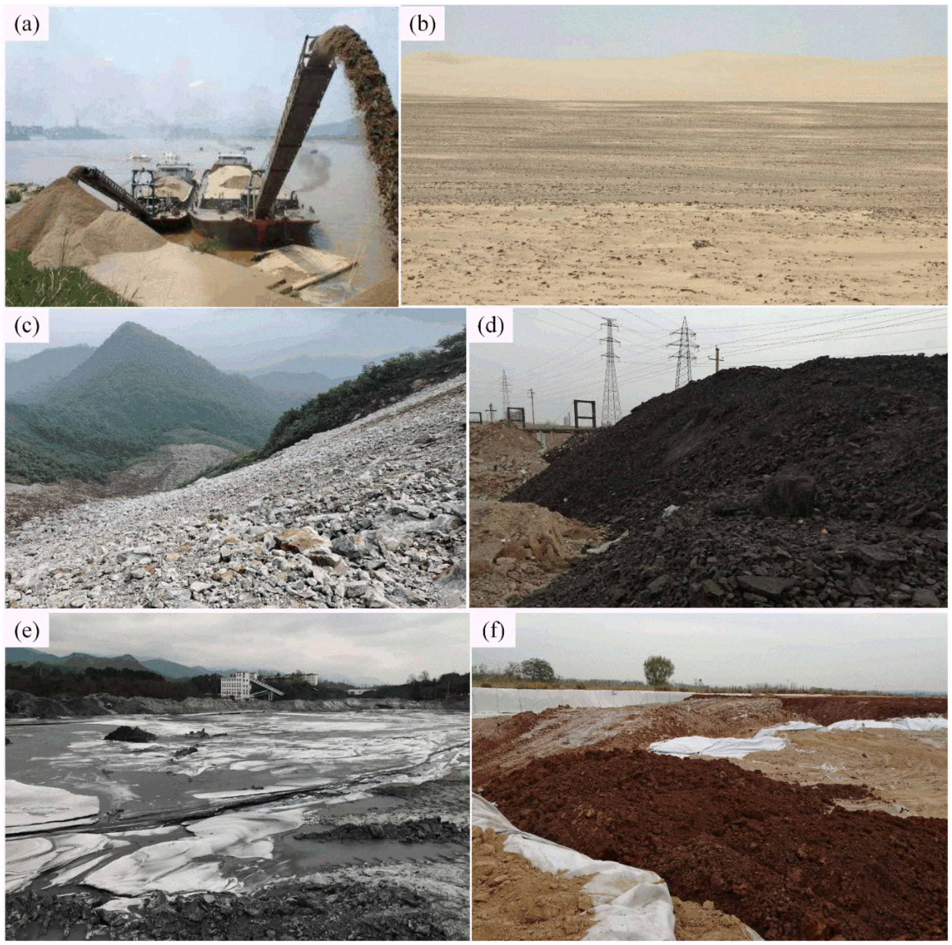
Figure 1 shows the development process of backfill technology in China.
Therefore, this paper (also an information article), as a medium to lead readers to China’s mining industry, mainly introduces two aspects to readers:
(1) Research progress of the high-concentration backfill theory in China;
(2) Research progress of high-concentration backfill equipment in China.

2. Research Progress of High-Concentration Backfill Theory in China

2.1. Paste-Like and Paste Backfill Technology

High-concentration backfill (filling) is a relative concept. Compared with traditional low-concentration backfill, high-concentration backfill has higher concentration, lower bleeding rate, shorter solidification time, higher early strength and better overall bearing and support effect after dehydration. At the same time, high-concentration backfill is also a very broad concept, and the backfill slurry with a mass concentration of more than 60% and s bleeding rate of less than 10% belongs to the category of high concentration. In order to facilitate the actual production management, improve the backfill effect and guarantee the backfill quality, paste and paste-like backfill technology with more accurate concentration ranges and clearer rheological states have emerged one after another. In any case, paste and paste-like are in the category of high-concentration backfill [13,14].
Paste backfill technology was first developed successfully in the Grund Lead-Zinc Mine in Germany in 1979. Due to its advantages, such as no bleeding, no precipitation and no segregation in the natural static state, it has quickly become a hot spot in the global mining green revolution technology. The team of Professor A.B. Fourie of the Australian Center for Rock Mechanics concluded that the content of −20 μm particles exceeded 15%, there was no segregation or bleeding in the natural static state, no stratification or settlement in pipeline transportation, the collapse degree was less than 230 mm and the rheological properties were non-Newtonian flow plastic bodies. Since it was successfully tested in Jin-chuan No.2 Mining Area for the first time in 1994, paste backfill technology has developed rapidly in China; however, it usually falls for the mistake of paying too much attention to “high concentration, no bleeding water” and ignoring liquidity, resulting in complex paste preparation process, poor liquidity of pipe transportation, high energy consumption of pumping and low stope backfill rate [13,15].
As a new type of the tailing backfill mode, paste-like technology has the advantages of good fluidity and easy transportation of cemented backfill slurry, high paste mass concentration, less underground dehydration and high strength of backfill consolidation, and has been paid more and more attention by scholars all over the world. Xinmin Wang from Central South University summarized the advantages of paste-like backfill: the higher the tailing mass concentration is, the lower the bleeding rate, and the higher the strength of backfill consolidation body is, the better the backfill effect. However, the higher the preparation cost is, the worse the fluidity and the higher the energy consumption for pipeline transportation. Therefore, the paste-like technology is the most economical and reasonable tailings backfill method at present under the condition of considering the backfill effect and the flow of pipe transportation, as shown in Figure 2.

2.2. New Backfill Materials

Backfill materials generally composed of backfill aggregate, cementitious materials and admixtures. The selection of backfill materials not only affects the quality of backfill body, but also directly affects the investment and cost of backfill system in mine. According to the actual conditions of the mine, materials or industrial wastes with wide sources, low costs, stable physical and chemical properties, non-toxicity and harmlessness and the skeleton function is generally selected as the backfill aggregate. At present commonly used include: tailings, waste rock, sand and river sand mountain, gobi aggregate, coal gangue, phosphogypsum and red mud. The recycling of solid waste as backfill aggregate not only solves the problem of the source of backfill aggregate, but also protects the surface environment and creates better economic and social and environmental benefits [16]. As shown in Figure 3, these are commonly used backfill aggregate sources in China.
Portland cement is the most widely used backfill cementing materials in China. In recent years, with the rising price of cement and the continuous high operation, many mines in China began to test the use of industrial wastes with certain cementing capacity as cement substitute materials to reduce the cost of cementing backfill, such as water quenching slag, fly ash, high water quick-setting materials, etc. [17,18] In addition, the emergence of new concrete materials has also brought some enlightenment to the development of backfill materials [19].
Slag and fly ash are volcanic ash materials, which are characterized by more active SiO2 and Al2O3 components. Under certain conditions, stable cementing calcium silicate hydrate and calcium aluminate hydrate double salt can be formed. During the hardening process, the strength increases with the age and has good late strength. At present, most of the new cementified materials sold on the market are powder materials formed by a variety of inorganic materials calcined at high temperature, and then an appropriate amount of natural minerals and chemical activator ingredients are added after grinding and homogenization. Most of the physical form is white and white fine powder, and the specific surface area is generally more than 4000 cm2/g. The main chemical components are SiO2, Al2O3, Fe2O3, CaO, MgO and so on [20]. Table 1 shows the main chemical composition of the volcanic ash materials commonly used in China, and Figure 4 shows the microstructure of the new cement substitute materials used in China.

2.3. Bearing Mechanism of Backfill Body

After nearly half a century of the continuous improvement and development of backfill mining technology in China, its application practice in engineering has become increasingly perfect. In view of different mining technical conditions, in-depth research on the bearing mechanism of backfill body, especially based on the special mining technical conditions of deep wells, systematic and in-depth research on deep well backfill theory and rockburst prevention and control technology, has become a new research hotspot and the development direction [21].
Particle size composition, particle size distribution, physical and chemical properties of tailings, the cement-sand ratio, mass concentration, permeability and dehydration performance, curing environment and other factors will affect the damage and failure characteristics of backfill. After entering the goaf, the backfill slurry interacts with surrounding rock through flow settlement, osmotic dehydration and consolidation hardening, including providing lateral pressure to the sliding trend of unloading rock blocks, supporting broken rock mass and primary cataclastic rock mass, and resisting the closure of surrounding rock in the stope [22]. From the perspective of energy, rockburst is a process of sudden and violent release of elastic deformation potential energy accumulated in rock mass, and the release rate of energy in rock mass directly affects the action intensity and damage effect of rockburst. At present, many researchers in China, such as Xibing Li and Shaofeng Wang from Central South University, are researching the stability of rockburst, surrounding rock and the bearing mechanism of backfill. Figure 5 shows the schematic diagram of coupling action between surrounding rock and backfill body [23].

2.4. Rheological Study on High Concentration Filled Slurry

Backfill slurry is generally transported into the goaf by pipeline. It is of great significance to fully analyze and master the rheological properties of backfill slurry for calculating the pipeline resistance of backfill slurry, preventing the settlement of coarse particles from blocking the pipe, and ensuring the stability and reliability of the whole pipeline transportation system. A large number of experimental studies have been carried out at home and abroad on the rheological properties of filled slurry and its influencing factors, and important progress has been made [4].
However, Wang Xinmin from Central South University found an obvious thixotropic phenomenon in the rheological test of the backfill slurry of Jinchuan tailings paste. At the same time, other Chinese researchers found that for high-concentration backfill slurry, mass concentration, water-cement ratio, shear rate and rest time all have a great impact on the backfill process. Figure 6 shows the shear thixotropic characteristics of the filled slurry [24].

2.5. Study on Creep Damage and Plastic Failure Characteristics of Backfill

After nearly half a century of continuous improvement and development of backfill mining technology, its application in engineering practice has become increasingly perfect. It has become a new research hotspot and the development direction to carry out in-depth research on the bearing mechanism of backfill and research on deep well backfill theory and rockburst prevention and control technology according to different mining technical conditions.
Wang Xinmin [4,21] from Central South University found that for high-concentration backfill, particle size composition, particle size distribution, physical and chemical properties of tailings, cement-sand ratio, mass concentration, permeability and dehydration performance, curing environment and other factors would affect the damage and failure characteristics of backfill. Therefore, they simplified the compression failure process of backfill into initial deformation stage, elastic deformation stage, plastic yield stage and failure stage.

3. Research Progress of High-Concentration Backfill Equipment in China

Due to the increase in direct mining cost, the backfill method is the first kind of method used in non-ferrous metal mines and precious metal mines. However, in recent years, with the rapid progress of backfill technology and equipment, the cost of backfill has been constantly reduced, and backfill method has been widely used in coal mines, iron mines, chemical mines and other mines. According to the backfill process, the special equipment for backfill includes: tailings concentration and the dehydration device, mixing device and pumping equipment. For high-concentration backfill, these pieces of equipment are very important. With the continuous development of China’s industry, great progress has been made in the research of high-concentration backfill equipment.
Figure 7 shows the relevant equipment.

3.1. Development Progress of Tailings Concentration and Dehydration Device

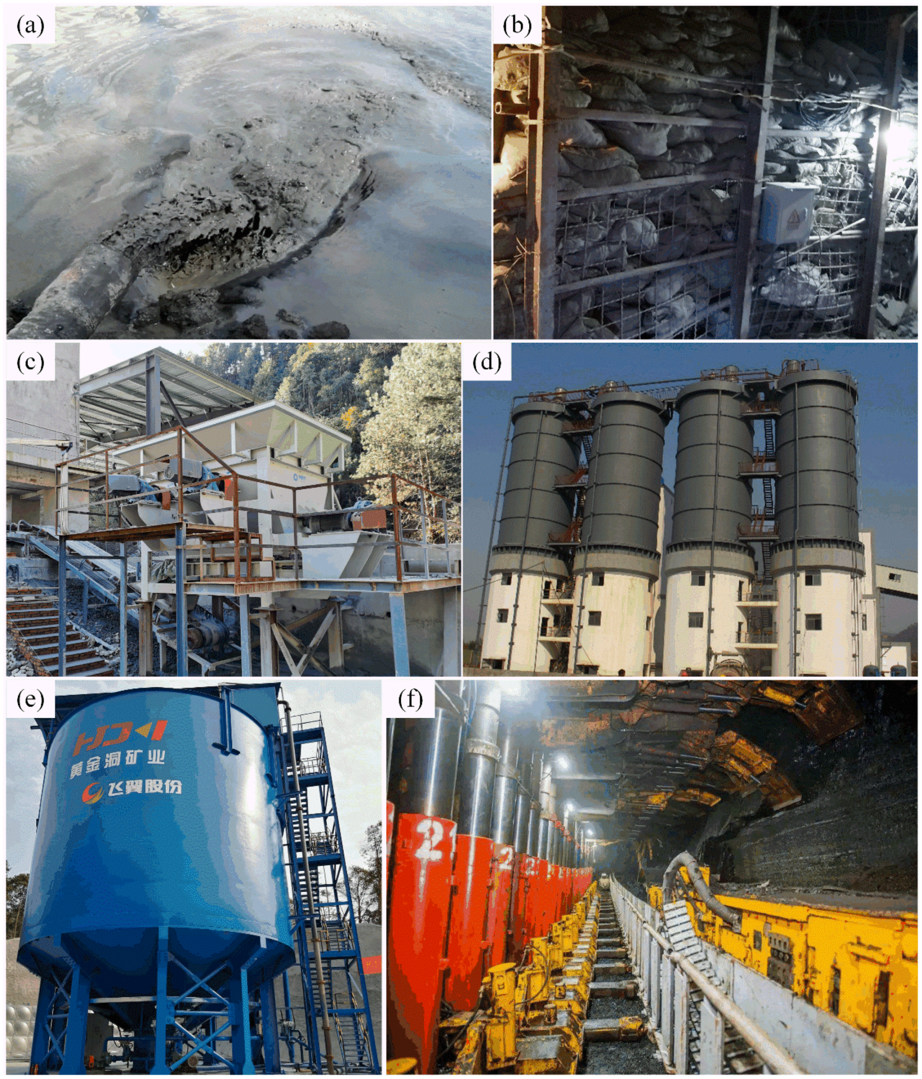
3.1.1. Hydrocyclone (Hydrocyclone Group)

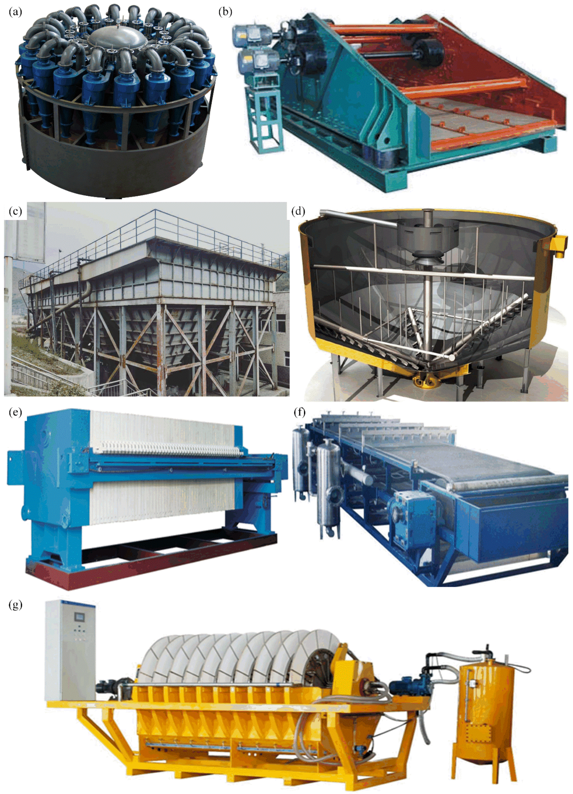
Hydrocyclone is a kind of classification equipment that uses centrifugal force to accelerate tailings settlement. It is one of the commonly used classification equipment for tailings backfill. It has the advantages of simple structure, low equipment cost and small occupation area [25,26]. In recent years, with the continuous maturity and development of the application of hydrocyclone in tailing backfill field, a hydrocyclone group, which is formed by several or dozens of hydrocyclones, began to appear and be applied in the backfill system of mines (see Figure 7a).

3.1.2. Vibrating Screen

A vibrating screen is a new type of tailings dehydration equipment for solid-liquid separation by controlling the yield of coarse and fine particle size of vibrating screen network (see Figure 7b). The high frequency vibration of the screen driven by the motor helps the water to rapidly infiltrate from the filter layer of the screen surface, and pushes the filter cake to move forward continuously. Therefore, it has high dehydration efficiency for coarse particles in the tailings. High frequency vibration dehydration screen is often used with hydrocyclone, thickener and filter press for tailings classification and dehydration. The processing capacity and dehydration effect of the vibrating screen is not only related to the size of the screen, but also has a great relationship with the vibration frequency and dehydration area. At present, the new high frequency vibrating screen is in effective control of the amplitude at the same time; the operation frequency has been increased to 1500–7200 r/min, gradually forming a single layer, a double layer until the declamination of high efficiency and a large capacity overlapping high frequency vibration dehydration screen series of products [27].

3.1.3. Vertical Sand Bin

As a typical aggregate concentration and storage equipment, a vertical sand bin is generally composed of bin top, overflow tank, bin bottom and pulping pipe fittings in the bin [28].
Bin roof structure includes a bin roof room, sand inlet pipe, hydrocyclone (tailings classification), material level gauge and pedestrian trestle, etc. The overflow groove is located in the inner or outer wall of the bin mouth, and the bottom of the groove has a slope toward the overflow pipe interface. The function of the overflow groove is to reduce the overflow speed and improve the utilization rate of tailings. The bin body is the main component of sand storage, generally built with reinforced concrete or directly welded steel plate, due to the past use of spherical silo bottom structure sand concentration is low and easy to harden, so the modern vertical sand bin has generally been changed to conical sand structure. A vertical sand bin is widely used in metal backfill mines, and the technology is relatively mature, but there are also many problems, such as small processing capacity, low sand discharge concentration and instability and the bin wall caving suddenly blocking sand discharge mouth, resulting in flow interruption, overflow water running muddy. In recent years, Chinese scholars have mostly improved the sand discharge concentration and reduced the solid content of overflow water by optimizing the types, addition methods and dosage of flocculant or coagulant aid, and have improved the sand discharge effect and reduced the blockage of flow by improving the design of the nozzle at the bottom of sand bin or using feng shui combined slurry [29].

3.1.4. Thickener

Thickener is based on the traditional rake thickener with flocculant adding device. The principle of flocculation sedimentation is used to condense fine particles into groups, which can reduce the diameter of thickener by more than 50%, reduce the area of occupation by about 20% and improve the processing capacity per unit area by several times. High-efficiency thickener has mature technology and wide application range, but there are also problems such as large footprint, small processing capacity and low concentration efficiency [30]. Figure 7c shows the inclined plate thickener, and Figure 7d shows the deep cone thickener.
At the same time, since the mass concentration of bottom flow of the high-efficiency thickener can only reach 40~50%, the high-efficiency thickener is often used as the equipment for thickening tailings of one stage, and a second-stage dehydration device is needed to obtain the high-concentration bottom flow that meets the requirements of mine backfill.
At present, the thickener is developing towards large-scale, high efficiency and automatic control. For example, on the basis of adding flocculant to the high efficiency thickener, the deep-cone thickener further increases the wall height and diameter to increase the tailings treatment efficiency, improve the bottom flow concentration and reduce the solid content of overflow water [31].

3.1.5. Filter and Filter Press

A filter and filter press are the most commonly used pieces of equipment in the second stage of tailings dehydration. According to the different principles of dehydration, the filter can be divided into vacuum filter and ceramic filter, as shown in Figure 7e–g.
The core of the disc vacuum filter is a disc composed of a number of separate fans. The disc rotates in a tank full of pulp. When passing through the filtration and adsorption area, the pressure difference is formed on both sides of the filter medium under the action of the vacuum pump, and solid particles can form filter cake on the surface of the filter cloth. A disc vacuum filter has the advantages of small occupation area, large processing capacity, easy to large-scale and a good application prospect. At present, the largest tailings filtration and dehydration equipment in China is the xPG-200 vacuum filter produced by Shenyang Mining Machinery Co., Ltd. which is located at Shenyang Province, China. The actual processing capacity of Skavarakino Gold Mine in Russia is 85p, and the water content of filter cake is controlled within 19%.
A filter press is a kind of tailings dehydration equipment to achieve solid-liquid separation by applying mechanical pressure on one side of the filter medium. Through mechanical extrusion and dehydration of pulp drying, dewatering product water content of filter press is very low. At present, the filter presses widely used in tailings dry heap dehydration are belt-type filter press, box-type filter press, vertical filter press and plate-frame filter press. Compared with the ceramic filter, the filter press has higher energy consumption and needs to change the filter cloth frequently, so the application of filter press in the field of mine backfill is less [32].
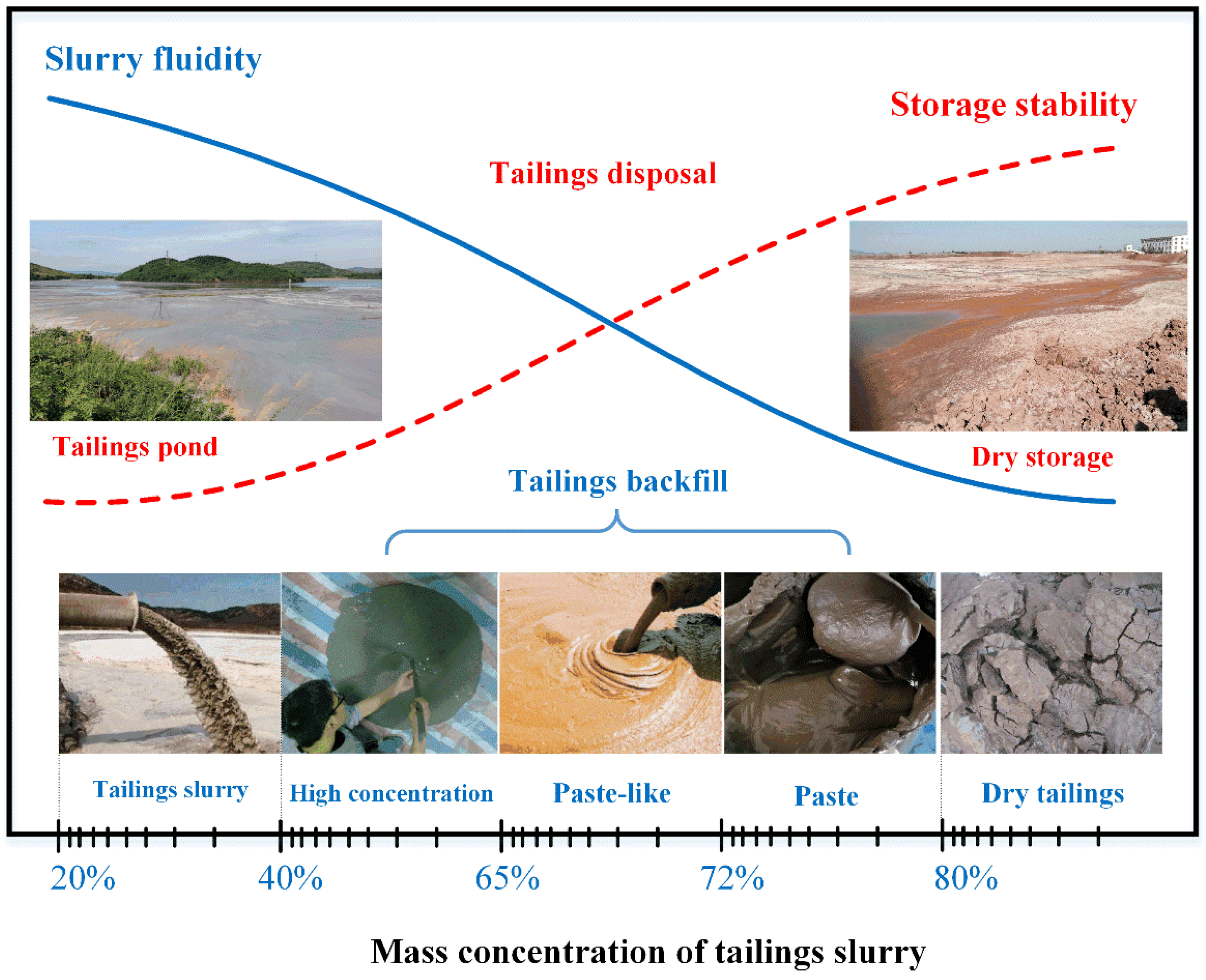
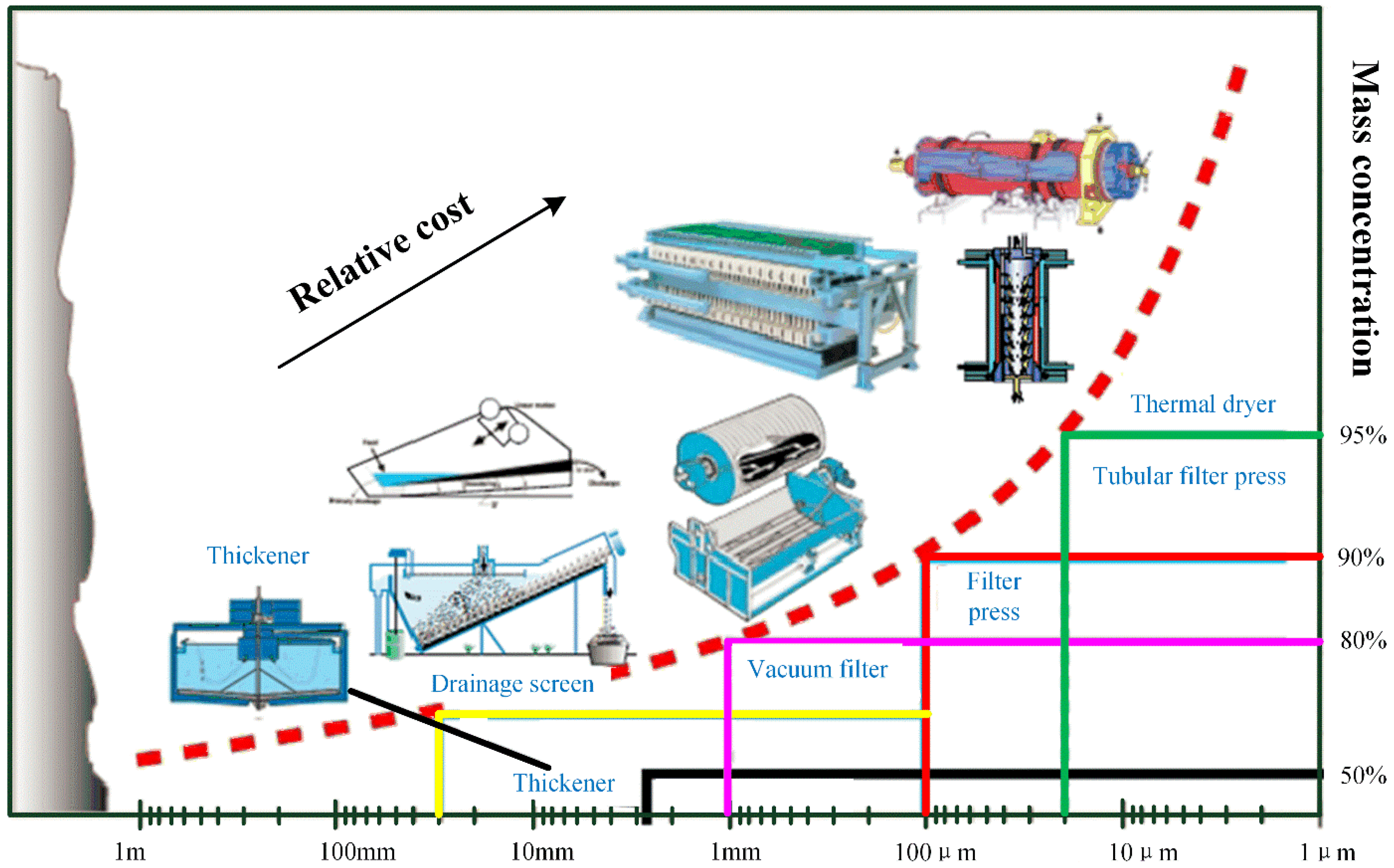
In addition, we have summarized a set of principle for the thickening and dehydration equipment selection for different tailings, which is intuitively presented in Figure 8.

3.2. Development Progress of Agitator

The preparation of high quality and high concentration slurry for backfill is the key of backfill technology, and the high efficiency and high-speed mixer is the most important equipment for the preparation of high concentration slurry.

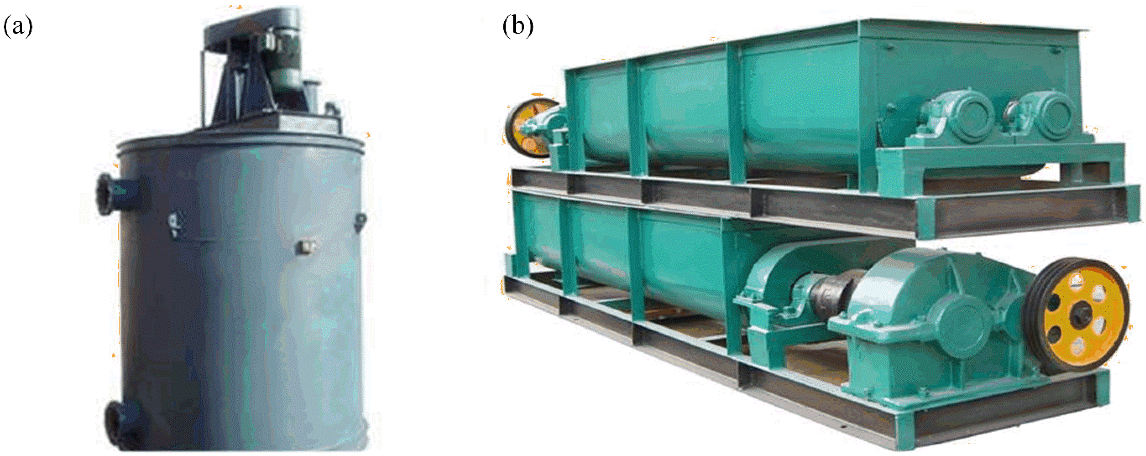
3.2.1. Mixing Barrel (Mixing Tank or Agitation Vat)

The mixing barrel is the most commonly used stirring equipment for mine backfill, which is driven by the motor triangle belt to rotate the impeller to fully mix and evenly different aggregates. It has the advantages of small investment, low cost and good applicability to aggregates with different particle sizes, as shown in Figure 9a [33].
Considering that in practical use, due to the interaction between solid particles and water in the prepared backfill material, it is easy to form agglomeration effect (agglomeration effect), which makes the core fragile agglomeration group adhere to a layer of cement slurry outside and is not easy to be pounded. Under the premise of not significantly increasing the stirring barrel power, continuously increasing the rotational speed of propeller blades is an effective means to solve such problems. At present, the mixing barrel with the power of 55 kW is commonly used in mines (the rotational speed is up to 240 r/min). Therefore, large capacity, high rotational speed and low energy consumption will be the development direction of the new type of mixing drum for mining backfill.

3.2.2. Horizontal Double Shaft Mixer

The mixing barrel has a good stirring effect for one or two kinds of mixed materials, but the stirring effect for a variety of materials is general.
However, a horizontal double-shaft mixer (See Figure 9b) has better mixing as well as mixing and conveying effect for more than two kinds of mixed materials. Its main parts include: stirring rotor rod, spindle, outer shell, motor, coupling, equipment frame and so on. When the double-shaft mixer is working, the backfill material enters the mixing tank through the feed port, and the two mixing shafts rotate in reverse under the motor drive. The mixing blades are installed on the mixing shaft, and the mixing blades are distributed in a spiral line on the mixing shaft. The backfill material is driven by the rotation of the mixing blades and then moves in the same direction, mixing each other to complete the mixing. In the overlapping area between the two mixing shafts of the two-axis mixer, the backfill materials with different rotation directions are extruded and rubbed together to improve the mixing effect of backfill materials.
Due to the horizontal double shaft mixer speed is generally not high, for viscous or agglomerate material stirring effect is general, agglomerate phenomenon is more obvious. Therefore, large capacity, high speed and low energy consumption are also the development directions of new horizontal double-shaft mixers for mining [34].

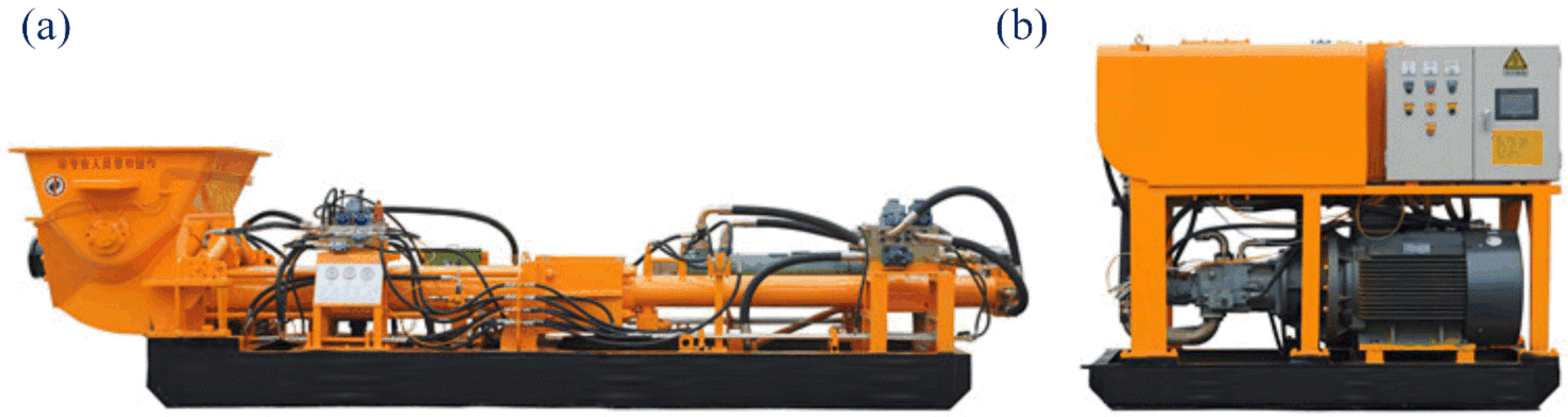
3.3. Development Progress of Backfill Industrial Pump

With the continuous development of backfill technology, the mass concentration of backfill slurry is increasing and the pipeline transportation distance is getting farther and farther. However, the long-distance pipeline transportation technology and equipment of high-concentration backfill slurry has always been a bottleneck restricting the development of backfill technology in China. In recent years, high pressure, large displacement, high reliability of backfill the emergence and rapid development of industrial pump have effectively solved the bottleneck problem; quick backfill mining in coal mines and metal mines has caused non-metallic mineral tailings backfill, high concentration of emissions, metallurgy, petrochemical industry wastewater treatment and solid waste treatment and other fields to be widely applied. It provides an effective guarantee for safe and reliable long-distance transportation of high solid and viscous materials, as shown in Figure 10 [35].

4. Discussion: The Development Direction of High-Concentration Backfill

Compared with the traditional backfill mining method, there are many innovations in high-concentration backfill mining. However, there is no doubt that the current high-concentration backfill technology in China is not developed, and the current high-concentration backfill in China mainly has the following two problems:
(1) The overall cost of the high-concentration backfill method is high;
(2) High-concentration backfill requires high-level backfill and production equipment.
Therefore, in order to continue to develop high-concentration backfill technology, China needs to solve these two problems.

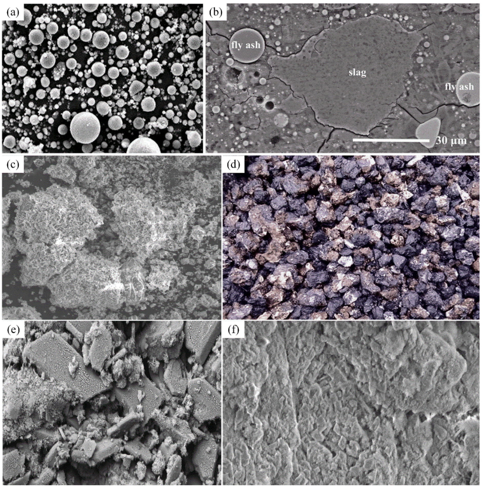
4.1. Research and Development of New Low Cost Cementing Materials

As raw material prices and the national attention to environmental protection are rising, cement as mine backfill is the most commonly used gelling material, as its prices stay high for a long time and there is still a larger rise space: some remote mining areas of bulk cement to ore prices have risen to RMB 500/t, therefore, development of a new mine backfill gelled material to replace cement has become a new research hotspot. A lot of research and application practice show that water quenching slag of smelter, fly ash of thermal power plant, yellow phosphorus slag of phosphorous chemical industry, red mud of sintering process and other materials are good cement substitutes [36,37].
For China, many mines in recent years have also begun to study the improvement of backfill materials:
(1) By adding fly ash into gangue backfill slurry in Shandong Sun-cun Coal Mine, not only the single consumption of cement is effectively reduced, but also the flow performance of backfill slurry and suspension performance of aggregate are greatly improved;
(2) Guizhou Kai-yang Phosphate Mine has developed the first international cemented backfill technology of total phosphorus waste with phosphogypsum as backfill aggregate and yellow phosphorus slag as cementing material.

4.2. Large-Capacity, High-Efficiency and Low-Cost Backfill Equipment

After nearly a century of development, the theory of backfill has formed a complete theoretical system and perfect application technology. However, in the actual backfill application process, backfill equipment is still an important prerequisite to restrict the successful application of backfill technology. For example, before the emergence of vertical sand silo, due to the lack of large capacity and high efficiency tailings concentration device, the traditional horizontal sand silo covers a large area, low water filtration efficiency, and serious overflow water running and mixing, resulting in a very small and discontinuous backfill capacity. After the emergence of the vertical sand silo, the horizontal sand silo was quickly eliminated, but the vertical sand silo in the application process also produced low sand concentration and instability, high energy consumption of high-pressure wind and high-pressure water combined slurry, so overflow water is easy to run and mix, plus there are many other problems [38].
Therefore, when the deep cone thickener with larger processing capacity, higher sand discharging concentration and more stability appeared, so the vertical sand silo was quickly eliminated. At present, the new backfill systems of large- and medium-sized mines at home and abroad almost all take the deep cone thickener as the core equipment. In addition, the large investment and high operating cost of backfill system are also the main reasons that limit the popularization and application of backfill in mines. At present, the paste backfill system with deep cone thickener as the core generally has an investment of RMB 25~50 million/set, and the backfill cost is generally as high as RMB 150~200/m3.
Therefore, the development of large capacity, high efficiency and low cost backfill equipment, and the continuous reduction of backfill system investment and backfill operation cost will be an important development direction of backfill technology.

5. Conclusions

In recent years, China has made great progress in mining engineering [39,40,41,42], especially high-concentration backfill. The main reasons for this are the development of new materials and technologies, such as the use of high-performance cementitious materials with higher content of CaO and MgO, as well as a more efficient utilization of existing resources. In addition to these improvements in technology, there is also an improvement in the understanding and application of basic science principles [43,44]. This paper reviews some important achievements that have been made recently by Chinese researchers on various aspects related to high-concentration backfill including its design principles, construction methods and performance characteristics; it also introduces a summary report on the latest research findings from several key laboratories across China [45,46].
Therefore, this paper, as a medium to lead readers to China’s mining industry, can be roughly divided into three sections:
(1) An introduction of the research progress of the high-concentration backfill theory in China;
In the first section: this paper primarily introduces paste-like and paste backfill technology, new backfill materials and the bearing mechanism of the backfill body in the high-concentration backfill progress.
(2) A description of the research progress of high-concentration backfill equipment in China.
In the first section: this paper primarily introduces the backfill equipment for the high-concentration backfill method, such as the backfill industrial pump.
(3) Discussion part.
In the discussion part, this paper mainly discusses the development direction of the backfill mining method.
As a medium to guide the readers to understand the development of mining industry in China, this paper systematically reviews the research progress of high-concentration backfill, which plays an important role in the future development of backfill mining. At the same time, we also call on relevant researchers to actively invest in backfill mining research to promote the rapid development of backfill mining methods, which will undoubtedly bring benefits to people around the world.
Finally, we claim that this information article only serves as a guide to start the dialogue, and we hope that more experts and scholars will be interested in and participate in research in this area.

Author Contributions

Conceptualization, S.L.; validation, H.Y. and Z.Y.; investigation, H.Y.; resources, S.L.; writing–original draft preparation, S.L.; writing–review and editing, H.Y. and S.L.; visualization, H.Y.; supervision, H.Y.; project administration, X.W.; funding acquisition, S.L. All authors have read and agreed to the published version of the manuscript.

Funding

This research was funded by the Natural Science Foundation of Hunan Province (Grant No. 2021JJ40745) and the National Natural Science Foundation of China (Grant No. 51804337).

Institutional Review Board Statement

Not applicable.

Informed Consent Statement

Not applicable.

Data Availability Statement

Not applicable.

Acknowledgments

First of all, the authors appreciate the financial support from the Natural Science Foundation of Hunan Province (Grant No. 2021JJ40745) and the Natural Science Foundation of China (Grant No. 51804337); secondly, the authors express gratitude to the Chinese experts in the research field of the backfill mining method for their effort in the development of China’s mining industry; finally, the authors express sincere thanks to Central South University.

Conflicts of Interest

The authors declare no conflict of interest.

References

  1. Li, S.; Zhao, Z.; Yu, H.; Wang, X. The recent progress China has made in the backfill mining method, part II: The composition and typical examples of backfill systems. Minerals 2021, 11, 1362. [Google Scholar] [CrossRef]
  2. Yu, H.; Li, S.; Wang, X. The recent progress China has made in the backfill mining method, part III: Practical engineering problems in stope and goaf backfill. Minerals 2022, 12, 88. [Google Scholar] [CrossRef]
  3. Hu, B.; Zhang, Q.; Li, S.; Yu, H.; Wang, X.; Wang, H. Application of numerical simulation methods in solving complex mining engineering problems in dingxi mine, China. Minerals 2022, 12, 123. [Google Scholar] [CrossRef]
  4. Yu, H.; Li, S.; Wang, X. The recent progress China has made in the backfill mining method, part I: The theory and equipment of backfill pipeline transportation. Minerals 2021, 11, 1274. [Google Scholar] [CrossRef]
  5. Liu, Y.; Liu, J.; Yang, B.; Yuan, S. Assessing water and sand inrushes hazard reductions due to backfill mining by combining gis and entropy methods. Mine Water Environ. 2021, 40, 956–969. [Google Scholar] [CrossRef]
  6. Sui, W.; Zhang, D.; Cui, Z.C.; Wu, Z.; Zhao, Q. Environmental implications of mitigating overburden failure and subsidences using paste-like backfill mining: A case study. Int. J. Min. Reclam. Environ. 2015, 29, 521–543. [Google Scholar] [CrossRef]
  7. Liu, J.; Sui, W.; Zhang, D.; Zhao, Q. Durability of water-affected paste backfill material and its clean use in coal mining. J. Clean. Prod. 2020, 250, 119576. [Google Scholar] [CrossRef]
  8. Yao, Y.; Cui, Z.; Wu, R. Development and challenges on mining backfill technology. J. Mater. Sci. Res. 2012, 1, 73. [Google Scholar] [CrossRef]
  9. Qi, C.; Fourie, A. Cemented paste backfill for mineral tailings management: Review and future perspectives. Miner. Eng. 2019, 144, 106025. [Google Scholar] [CrossRef]
  10. Qiu, J.; Yang, L.; Sun, X.; Xing, J.; Li, S. Strength characteristics and failure mechanism of cemented super-fine unclassified tailings backfill. Minerals 2017, 7, 58. [Google Scholar] [CrossRef] [Green Version]
  11. Cao, S.; Song, W.; Yilmaz, E. Influence of structural factors on uniaxial compressive strength of cemented tailings backfill. Constr. Build. Mater. 2018, 174, 190–201. [Google Scholar] [CrossRef]
  12. Chen, Q.; Zhang, Q.; Wang, X.; Xiao, C.; Hu, Q. A hydraulic gradient model of paste-like crude tailings backfill slurry transported by a pipeline system. Environ. Earth Sci. 2016, 75, 1–9. [Google Scholar] [CrossRef]
  13. Guo, Y.; Ran, H.; Feng, G.; Du, X.; Zhao, Y.; Xie, W. Deformation and instability properties of cemented gangue backfill column under step-by-step load in constructional backfill mining. Environ. Sci. Pollut. Res. 2022, 29, 2325–2341. [Google Scholar] [CrossRef] [PubMed]
  14. Chen, Q.S.; Zhang, Q.L.; Fourie, A.; Chen, X.; Qi, C.C. Experimental investigation on the strength characteristics of cement paste backfill in a similar stope model and its mechanism. Constr. Build. Mater. 2017, 154, 34–43. [Google Scholar] [CrossRef]
  15. Liu, L.; Xin, J.; Feng, Y.; Zhang, B.; Song, K.I. Effect of the cement—Tailing ratio on the hydration products and microstructure characteristics of cemented paste backfill. Arab. J. Sci. Eng. 2019, 44, 6547–6556. [Google Scholar] [CrossRef]
  16. Zhang, J.; Li, M.; Taheri, A.; Zhang, W.; Wu, Z.; Song, W. Properties and application of backfill materials in coal mines in China. Minerals 2019, 9, 53. [Google Scholar] [CrossRef] [Green Version]
  17. Zhu, X.; Guo, G.; Liu, H.; Peng, X.; Yang, X. Stability analysis of the composite support pillar in backfill-strip mining using particle flow simulation method. Environ. Earth Sci. 2022, 81, 1–19. [Google Scholar] [CrossRef]
  18. Zhou, N.; Zhang, J.; Ouyang, S.; Deng, X.; Dong, C.; Du, E. Feasibility study and performance optimization of sand-based cemented paste backfill materials. J. Clean. Prod. 2020, 259, 120798. [Google Scholar] [CrossRef]
  19. Ma, C.; Liu, Y.T.; Song, D.Q.; Cao, L.; He, F.Q.; Liu, X.L.; Zhou, H.J. Characterizing the influencing factors in a novel repairing material for concrete structures by AC impedance spectroscopy. J. Build. Eng. 2021, 47, 103858. [Google Scholar] [CrossRef]
  20. Luan, H.; Jiang, Y.; Lin, H.; Wang, Y. A new thin seam backfill mining technology and its application. Energies 2017, 10, 2023. [Google Scholar] [CrossRef] [Green Version]
  21. Shao, X.; Li, X.; Wang, L.; Fang, Z.; Zhao, B.; Liu, E.; Liu, L. Study on the pressure-bearing law of backfilling material based on three-stage strip backfilling mining. Energies 2020, 13, 211. [Google Scholar] [CrossRef] [Green Version]
  22. Zhang, J.W.; Wang, H.L.; Chen, S.J. Bearing capacity of backfill body and roof stability during strip coal pillar extracted with paste backfill. Geotech. Geol. Eng. 2018, 36, 235–245. [Google Scholar] [CrossRef]
  23. Yilmaz, E.; Belem, T.; Benzaazoua, M. Specimen size effect on strength behavior of cemented paste backfills subjected to different placement conditions. Eng. Geol. 2015, 185, 52–62. [Google Scholar] [CrossRef]
  24. Wang, S.; Li, S.; Qin, J.C.; Xiao, G.Z.; Yang, G.C.; Feng, X. Effect of anionic polyacrylamide on the structural stability of thickened tailings slurry in pipeline transportation. Adv. Mater. Sci. Eng. 2018, 2018, 7131487. [Google Scholar] [CrossRef] [Green Version]
  25. Cilliers, J.J.; Hinde, A.L. An improved hydrocyclone model for backfill preparation. Miner. Eng. 1991, 4, 683–693. [Google Scholar] [CrossRef]
  26. Toprak, N.A.; Altun, O. Considering hydrocyclone operation for tailings dewatering purpose and its effects on product specifications of paste backfill operations. Miner. Eng. 2021, 173, 107176. [Google Scholar] [CrossRef]
  27. Chang, Q.; Chen, J.; Zhou, H.; Bai, J. Implementation of paste backfill mining technology in Chinese coal mines. Sci. World J. 2014, 2014, 821025. [Google Scholar] [CrossRef]
  28. Shi, X.Z.; Hu, H.Y.; Du, X.H.; Li, M.L.; Wang, H.Y. Experimental study on flocculating sedimentation of tailings slurry in a vertical sand tank. Min. Metall. Eng. 2010, 30, 1–3. [Google Scholar]
  29. Wang, X.M.; Zhao, B.; Zhang, Q.L.; Xu, D.S. Cemented backfilling technology with unclassified tailings based on vertical sand silo. J. Cent. South Univ. Technol. 2008, 15, 801–807. [Google Scholar] [CrossRef]
  30. Ruan, Z.; Wang, Y.; Wu, A.; Yin, S.; Jin, F. A theoretical model for the rake blockage mitigation in deep cone thickener: A case study of lead-zinc mine in China. Math. Probl. Eng. 2019, 2019, 2130617. [Google Scholar] [CrossRef] [Green Version]
  31. Jiao, H.; Wu, A.; Wang, H.; Zhong, S.; Ruan, R.; Yin, S. The solids concentration distribution in the deep cone thickener: A pilot scale test. Korean J. Chem. Eng. 2013, 30, 262–268. [Google Scholar] [CrossRef]
  32. Yan, J.; Wang, Y.; Tu, Y.; Han, P.; Liu, X.; Ye, S. Green treatment of cyanide tailings using a “Filter press backwash–Chemical precipitation–Gaseous membrane absorption” method. Appl. Sci. 2021, 11, 2091. [Google Scholar] [CrossRef]
  33. Li, B.; Yan, H.; Zhang, J.; Zhou, N. Compaction property prediction of mixed gangue backfill materials using hybrid intelligence models: A new approach. Constr. Build. Mater. 2020, 247, 118633. [Google Scholar] [CrossRef]
  34. Zhang, H.; Feng, P.; Ying, W. Abrasive wear and optimal installation angle of concrete double-horizontal shaft mixer stirring blades. SN Appl. Sci. 2020, 2, 1–10. [Google Scholar] [CrossRef]
  35. Yang, K.; Zhao, X.; Wei, Z.; Zhang, J. Development overview of paste backfill technology in China’s coal mines: A review. Environ. Sci. Pollut. Res. 2021, 28, 67957–67969. [Google Scholar] [CrossRef] [PubMed]
  36. Li, S.; Zhang, R.; Feng, R.; Hu, B.; Wang, G.; Yu, H. Feasibility of recycling bayer process red mud for the safety backfill mining of layered soft bauxite under coal seams. Minerals 2021, 11, 722. [Google Scholar] [CrossRef]
  37. Li, S.; Zhang, Y.; Feng, R.; Yu, H.; Pan, J.; Bian, J. Environmental safety analysis of red mud-based cemented backfill on groundwater. Int. J. Environ. Res. Public Health 2021, 18, 8094. [Google Scholar] [CrossRef]
  38. Yin, S.; Shao, Y.; Wu, A.; Wang, H.; Liu, X.; Wang, Y. A systematic review of paste technology in metal mines for cleaner production in China. J. Clean. Prod. 2020, 247, 119590. [Google Scholar] [CrossRef]
  39. Di Nardo, M.; Yu, H. Special issue “Industry 5.0: The prelude to the sixth industrial revolution”. Appl. Syst. Innov. 2021, 4, 45. [Google Scholar] [CrossRef]
  40. Yu, H.; Li, S. The function design for the communication-based train control (CBTC) system: How to solve the problems in the underground mine rail transportation? Appl. Syst. Innov. 2021, 4, 31. [Google Scholar] [CrossRef]
  41. Nardo, M.D.; Yu, H. Intelligent ventilation systems in mining engineering: Is zigbee wsn technology the best choice? Appl. Syst. Innov. 2021, 4, 42. [Google Scholar] [CrossRef]
  42. Li, S.; Wang, G.; Yu, H.; Wang, X. Engineering project: The method to solve practical problems for the monitoring and control of driver-less electric transport vehicles in the underground mines. World Electr. Veh. J. 2021, 12, 64. [Google Scholar] [CrossRef]
  43. Zhang, B.; Xin, J.; Liu, L.; Guo, L.; Song, K.I. An experimental study on the microstructures of cemented paste backfill during its developing process. Adv. Civ. Eng. 2018, 2018, 9783046. [Google Scholar] [CrossRef]
  44. Xu, W.; Chen, W.; Tian, M.; Guo, L. Effect of temperature on time-dependent rheological and compressive strength of fresh cemented paste backfill containing flocculants. Constr. Build. Mater. 2021, 267, 121038. [Google Scholar] [CrossRef]
  45. Zheng, J.; Guo, L.; Sun, X.; Li, W.; Jia, Q. Study on the strength development of cemented backfill body from lead-zinc mine tailings with sulphide. Adv. Mater. Sci. Eng. 2018, 2018, 7278014. [Google Scholar] [CrossRef] [Green Version]
  46. Li, W.; Guo, L.; Liu, G.; Pan, A.; Zhang, T. Analytical and experimental investigation of the relationship between spread and yield stress in the mini-cone test for cemented tailings backfill. Constr. Build. Mater. 2020, 260, 119770. [Google Scholar] [CrossRef]
Figure 1. The development process of backfill technology in China: (a) schematic diagram of sand backfill; (b) waste rock dry backfill; (c) graded tailings backfill system; (d) full tailings backfill system; (e) paste backfill system; (f) high-water quick-setting backfill. Image source (ae): taken by authors; image source (f): https://www.sohu.com/a/438644662_358956 (accessed on 18 February 2022).
Sustainability 14 02758 g001
Figure 2. The mass concentration of tailings slurry and flow pattern division. Image source: taken by authors.
Sustainability 14 02758 g002
Figure 3. Commonly used backfill aggregate sources: (a) river sand; (b) Gobi sand; (c) mine excavation of waste rock; (d) coal gangue; (e) strong acid phosphogypsum; (f) strongly alkaline red mud. Image source (a): https://www.sohu.com/a/435113802_800178 (accessed on 18 February 2022); image source (b): https://bbs.hlgnet.com/info/u1_18103903 (accessed on 18 February 2022); image source (cf): taken by authors.
Sustainability 14 02758 g003
Figure 4. Microstructure of new cement substitute materials: (a) SEM figure of fly ash; (b) SEM of fly ash slag; (c) SEM map of coal gangue; (d) morphology of smelting slag; (e) SEM of phosphorus slag; (f) SEM of steel slag. Image source (a,b): http://www.mianfeiwendang.com/doc/34be220bb2bcd174055fcf33 (accessed on 18 February 2022); image source (c,e,f): taken by authors; image source (d): https://baike.baidu.com/item/%E6%B8%85%E7%82%89%E6%B8%A3/14477035 (accessed on 18 February 2022).
Sustainability 14 02758 g004
Figure 5. The schematic diagram of coupling action between surrounding rock and backfill body (image source from [23]).
Sustainability 14 02758 g005
Figure 6. The shear thixotropic characteristics of the filled slurry: (a) the microstructure of the filled slurry in the static state; (b) microstructure of the slurry after shear mixing; (c) microstructure of the slurry after shear mixing; (d) schematic diagram of shear rheological mechanism of backfill slurry. Image source (ac): taken by authors; image source (d) from [24].
Sustainability 14 02758 g006
Figure 7. Tailings thickener dehydration equipment: (a) hydrocyclone; (b) high frequency vibration dehydration sieve; (c) inclined plate thickener; (d) deep cone thickener; (e) plate and frame filter press; (f) belt vacuum filter; (g) ceramic filter. Image source (a): https://b2b.hc360.com/supplyself/571519270.html?confr=B12 (accessed on 18 February 2022); image source (b): http://www.chinafa.org/enterprise/u21091557669848.html (accessed on 18 February 2022); image source (c): http://www.nzrhb.com/aspcms/news/2019-3-19/685.html (accessed on 18 February 2022); image source (e): http://groups.tianya.cn/post-yzt-h696710296.shtml (accessed on 18 February 2022); image source (f): http://www.zkdsglj.cn/item/3095.html (accessed on 18 February 2022); image source (g): http://byksjx.machineryinfo.net/product/65940028.htm (accessed on 18 February 2022).
Sustainability 14 02758 g007
Figure 8. Principle of selection of tailings thickening and dewatering equipment (the corresponding author will explain the source of this figure upon request).
Sustainability 14 02758 g008
Figure 9. Agitator equipment: (a) mixing barrel; (b) horizontal double shaft mixer. Image source (a): http://byksjx.machineryinfo.net/product/65940028.htm (accessed on 18 February 2022); image source (b): http://www.kuyibu.com/c_ddc2836950/p22589921.html (accessed on 18 February 2022).
Sustainability 14 02758 g009
Figure 10. Backfill industrial pump: (a) pumping part; (b) dynamic component. Image source: https://hnrealtop.en.made-in-china.com/product/GKFEDqRVhfcW/China-Mining-Concrete-Pump-HGBS-200-15-800-.html (accessed on 18 February 2022).
Sustainability 14 02758 g010
Table 1. Main chemical composition of volcanic ash material (%).
Volcanic Ash MaterialSiO2Al2O3Fe2O3CaOMgONa2O + K2OSO3Ignition Loss
Tuff4~7311~192.6~6.42~1.40.4~22.4~10-7~16
Power plant fly ash43~5620~324~101.5~50.6~21~2.53~1.53~20
Coal gangue40~1515~352~91~71~41~2.5-12~17
Iron blast furnace slag26~426~170.15~238~491~13---
Bessemer slag8~200.6~66.5~3042~50----
Reflecting slag of steelmaking furnace35.53.6Fe 367.91.9-S 0.9-
Water quenched slag of lead smelting17.64.0Fe 27.4201.37-S 1.3-
Sintered red mud20~235~88~1243~461~2-6~10-
Publisher’s Note: MDPI stays neutral with regard to jurisdictional claims in published maps and institutional affiliations.

