
The Stability of Roadway Groups under Rheology Coupling Mining Disturbance

 , ,
, ,
Abstract
:1. Introduction
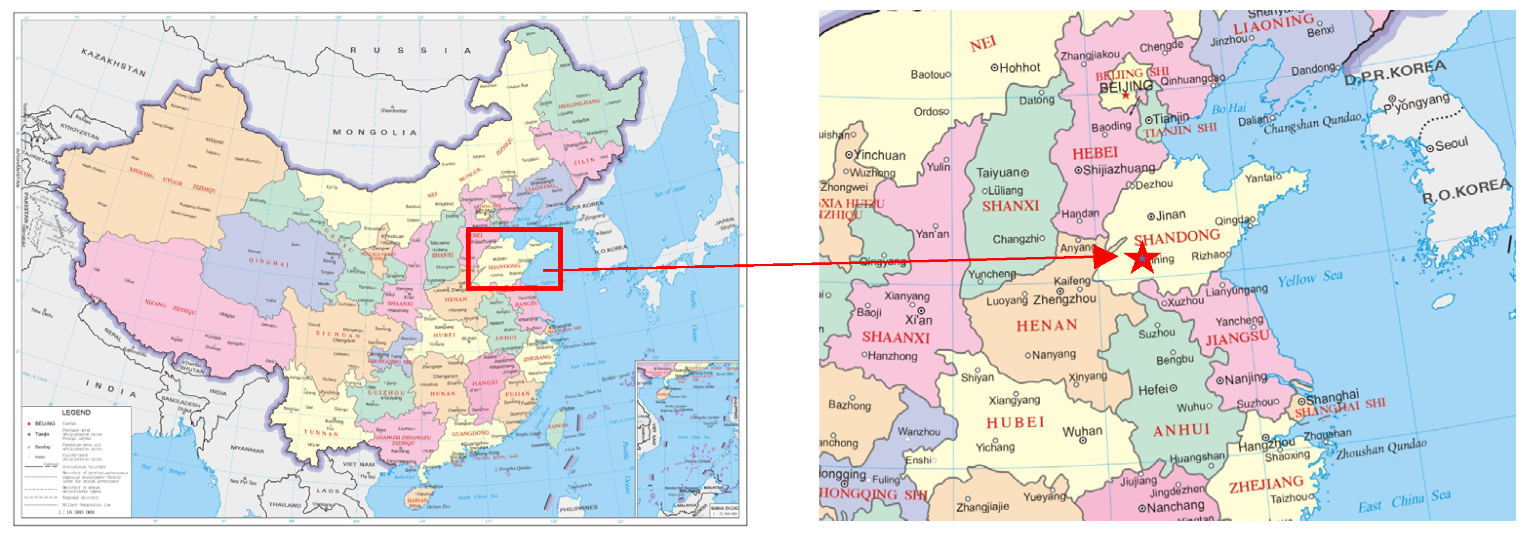
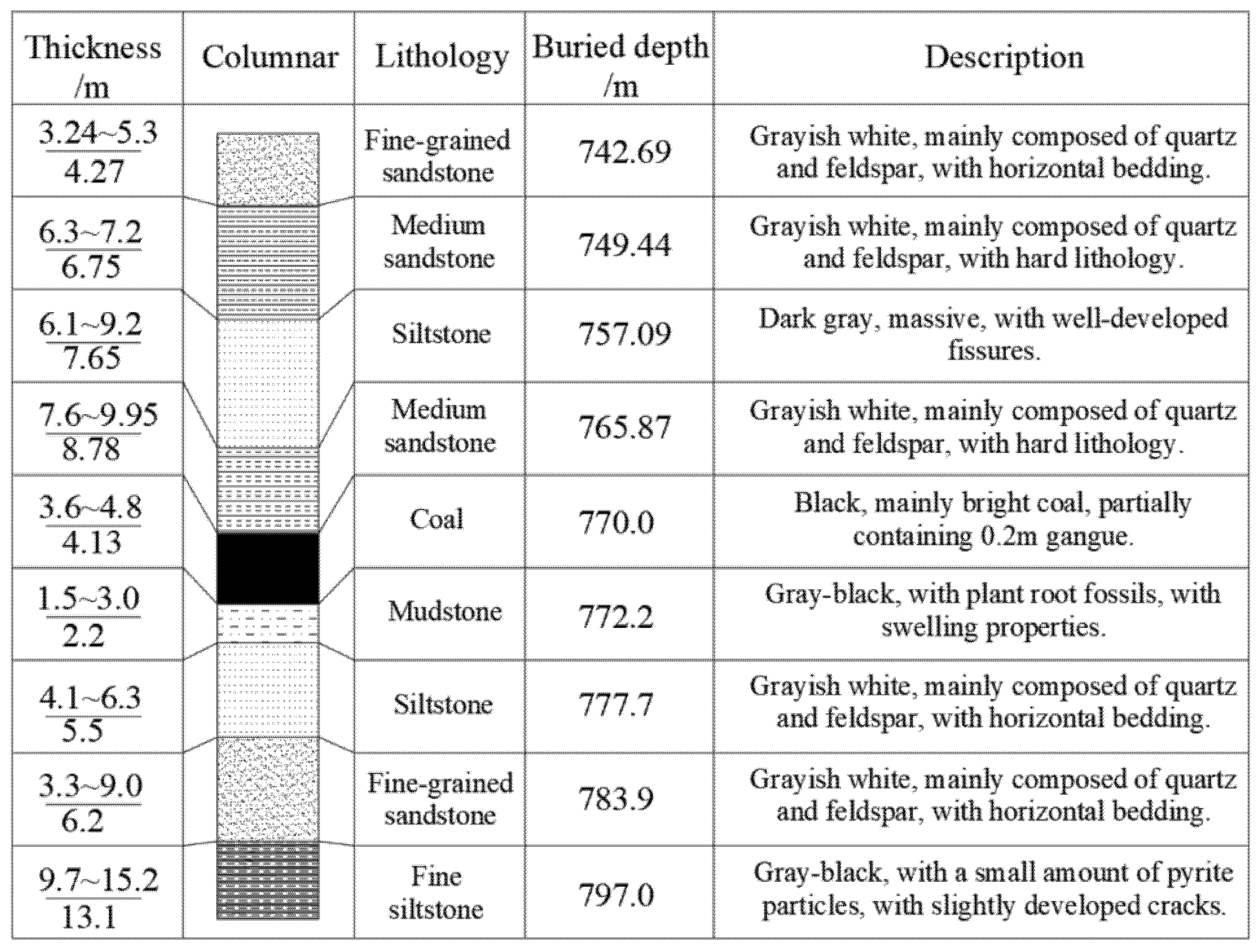
2. Project Overview
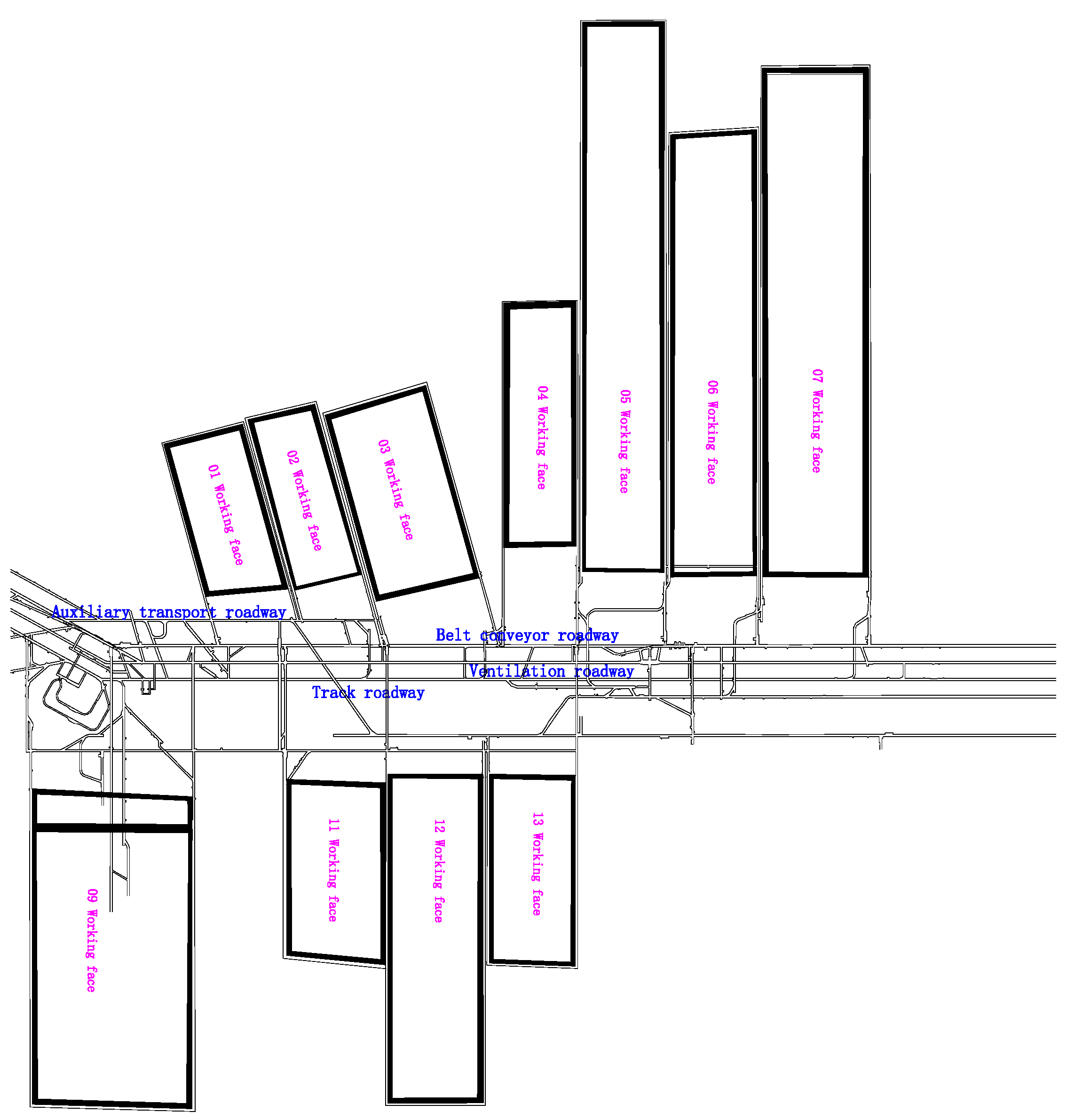
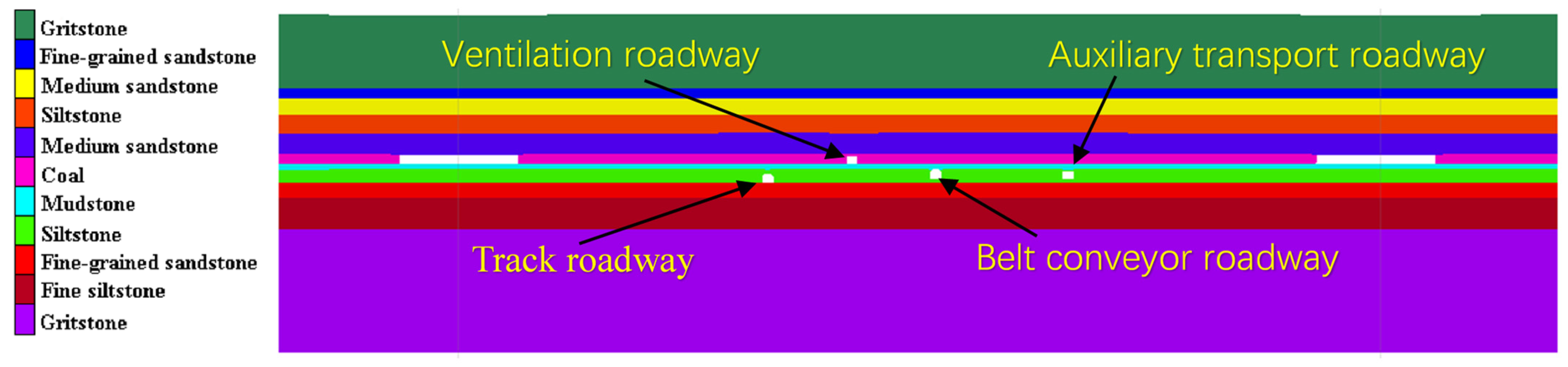
2.1. Position Relationship between Working Face and Roadway
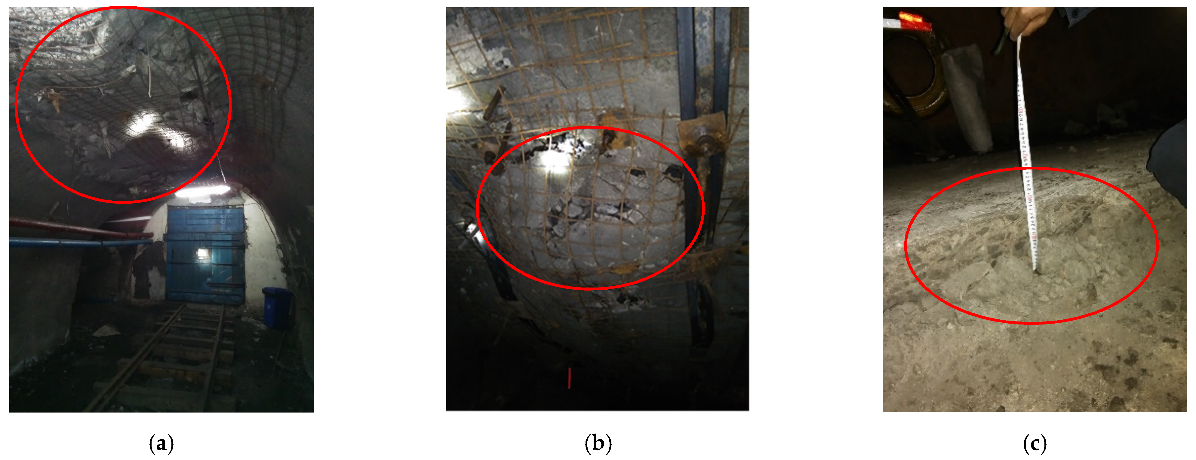
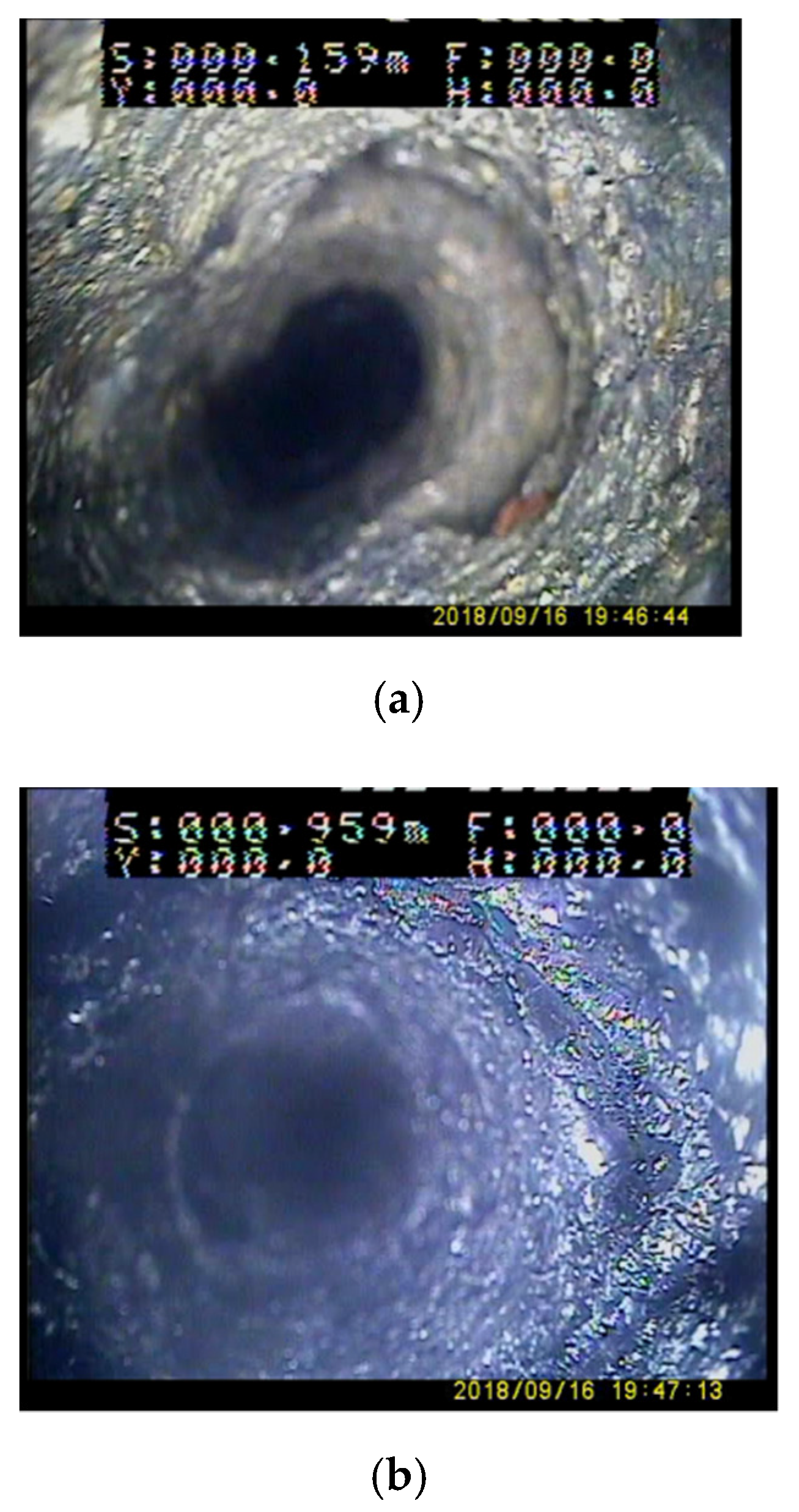
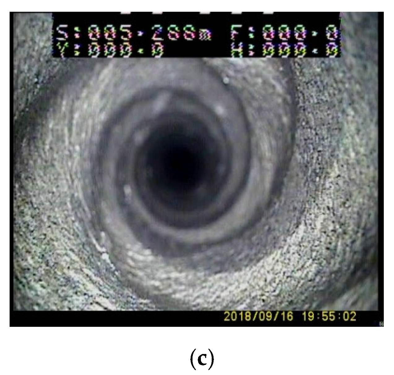
2.2. The Influence of Working Face Rheological Coupling Mining on Roadway Stability
3. Establishment of a Numerical Simulation Model for Disturbance Effect of Roadway Groups in a Deep Well
3.1. Numerical Simulation Modeling Process
3.2. Numerical Simulation Scheme
4. Results and Discussion on Coupling Disturbance of Rheology and Mining in Deep Mine Roadway Groups
4.1. Influence of Rheological Disturbance during Roadway Excavation
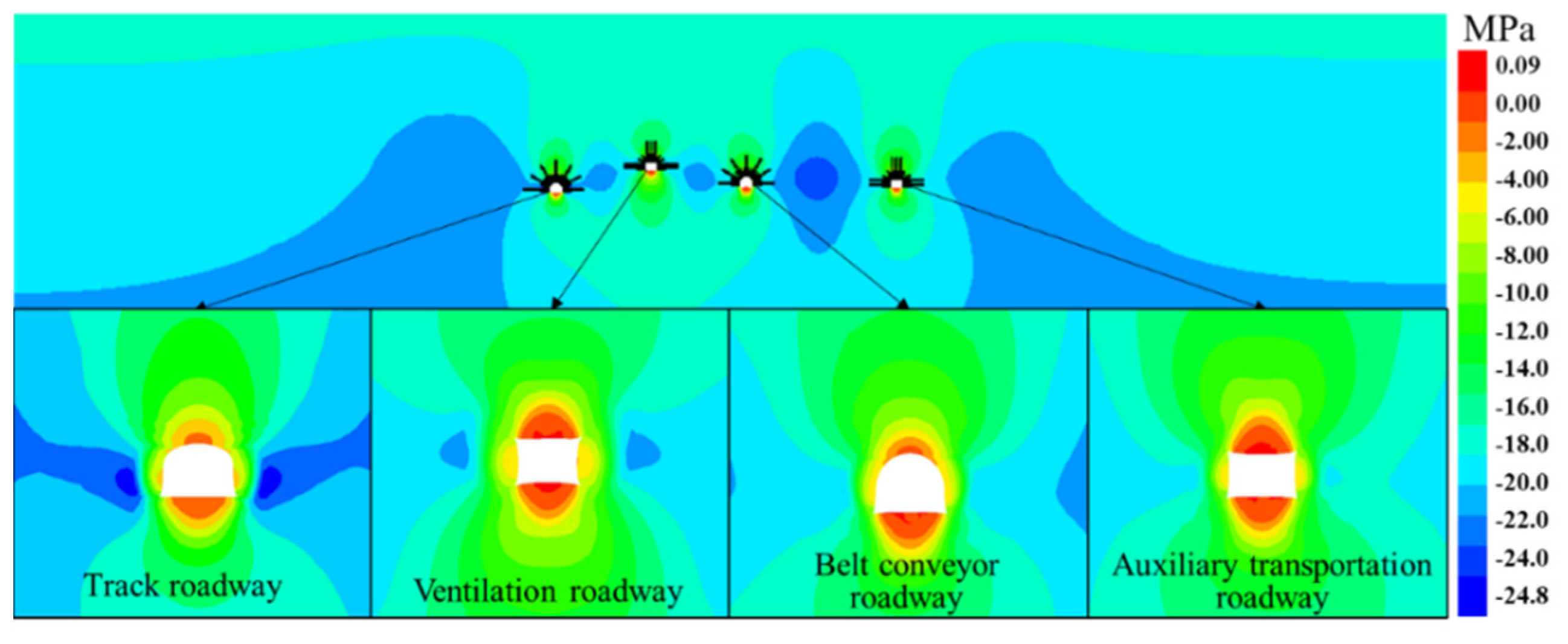
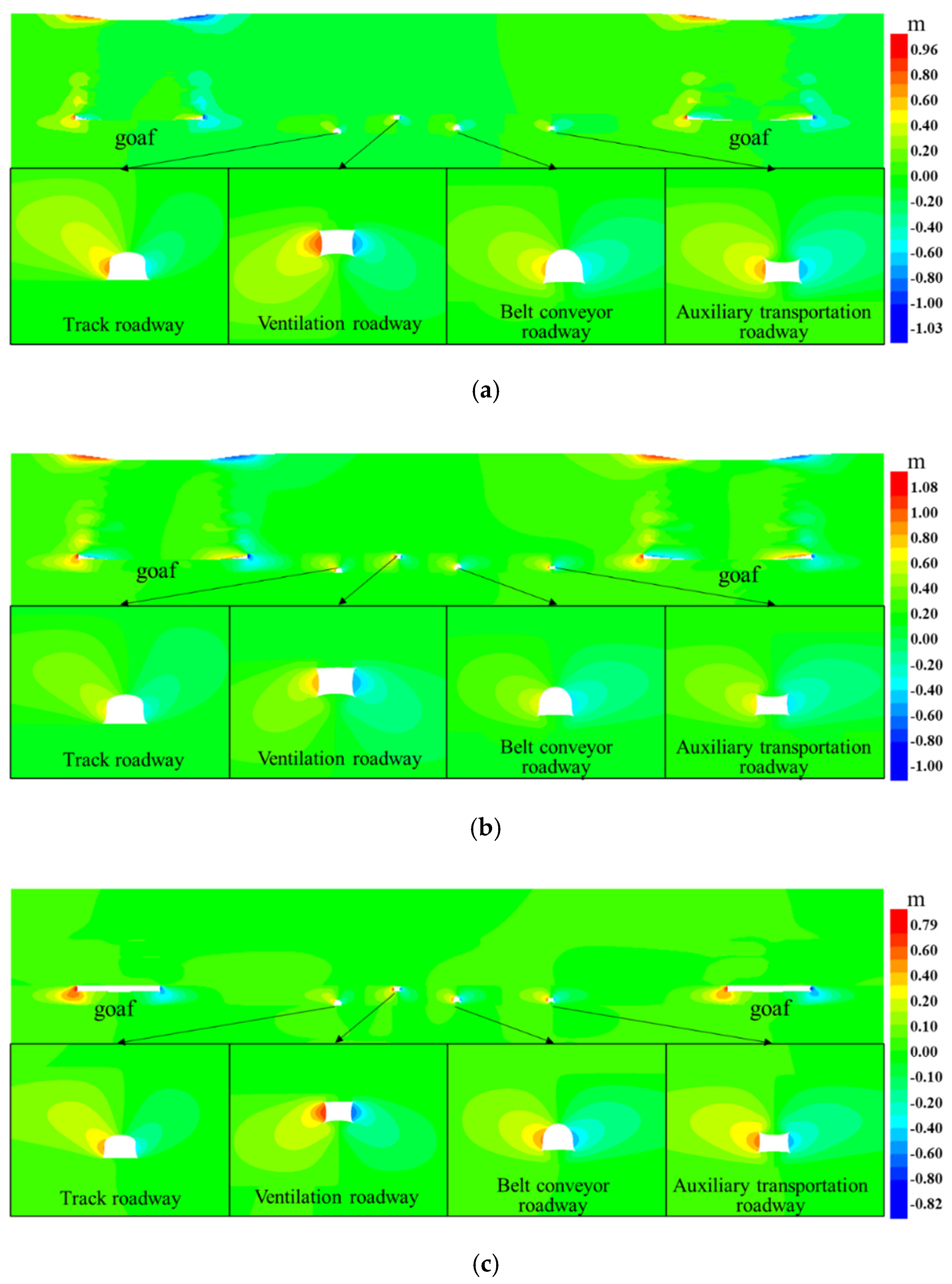
4.2. The Influence of Rheological Coupling Mining of Working Face on Stress Disturbance of Roadway Groups
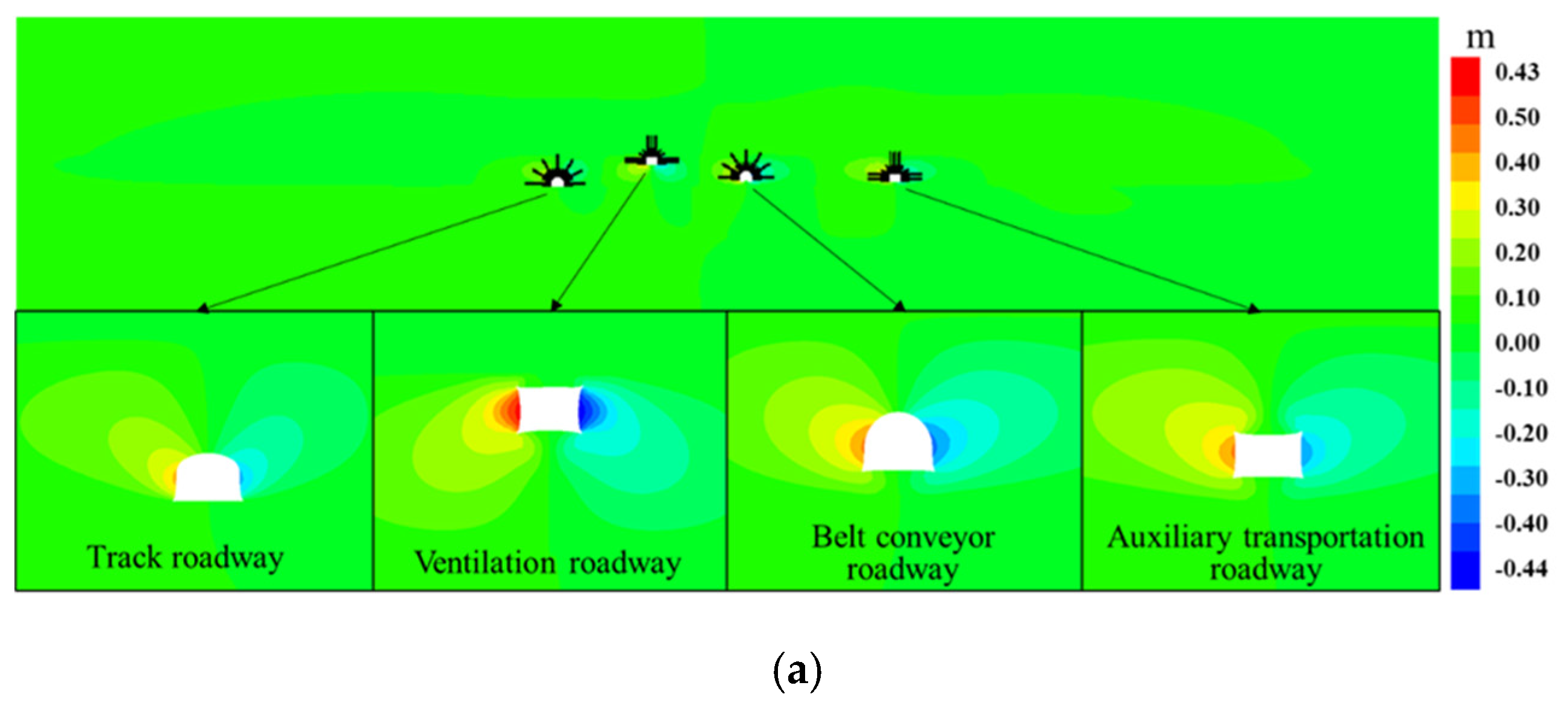
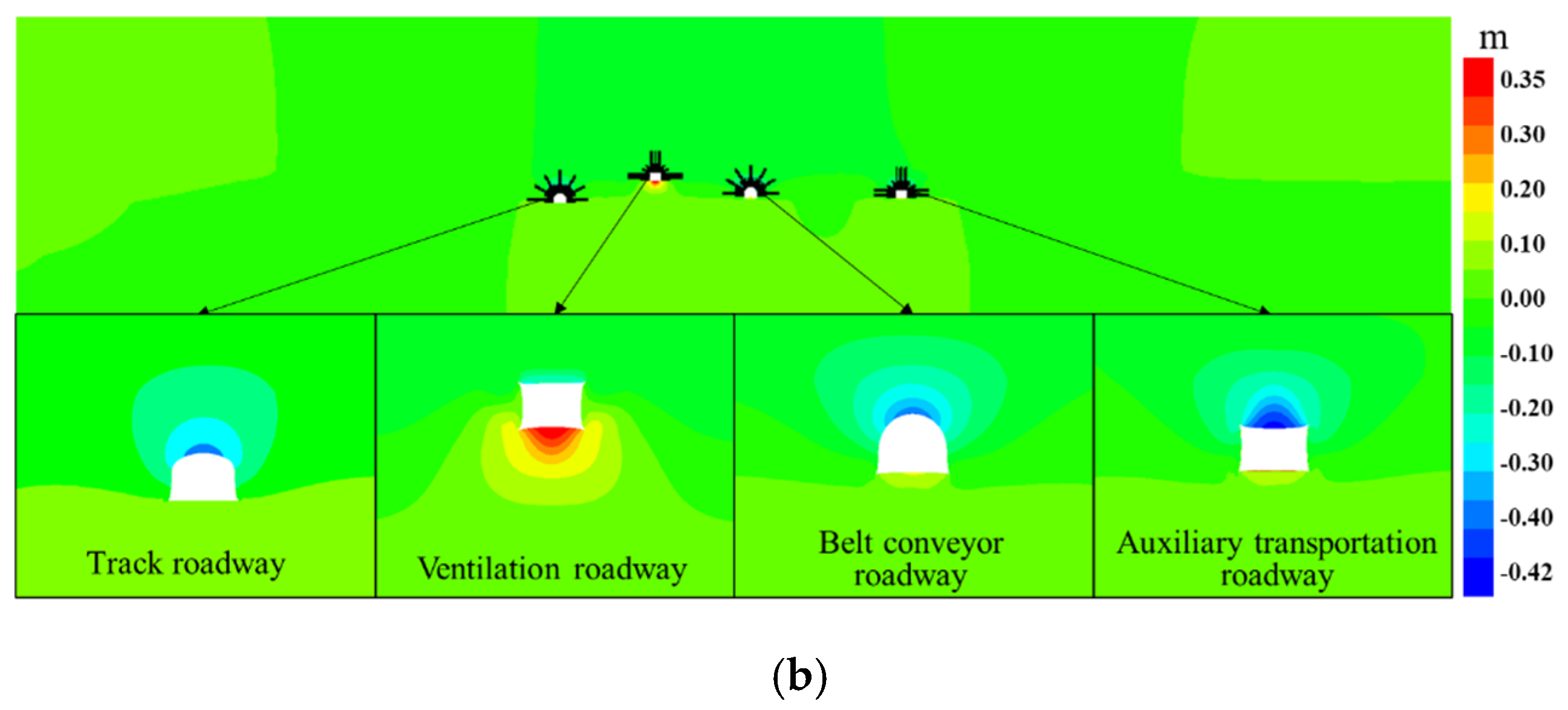
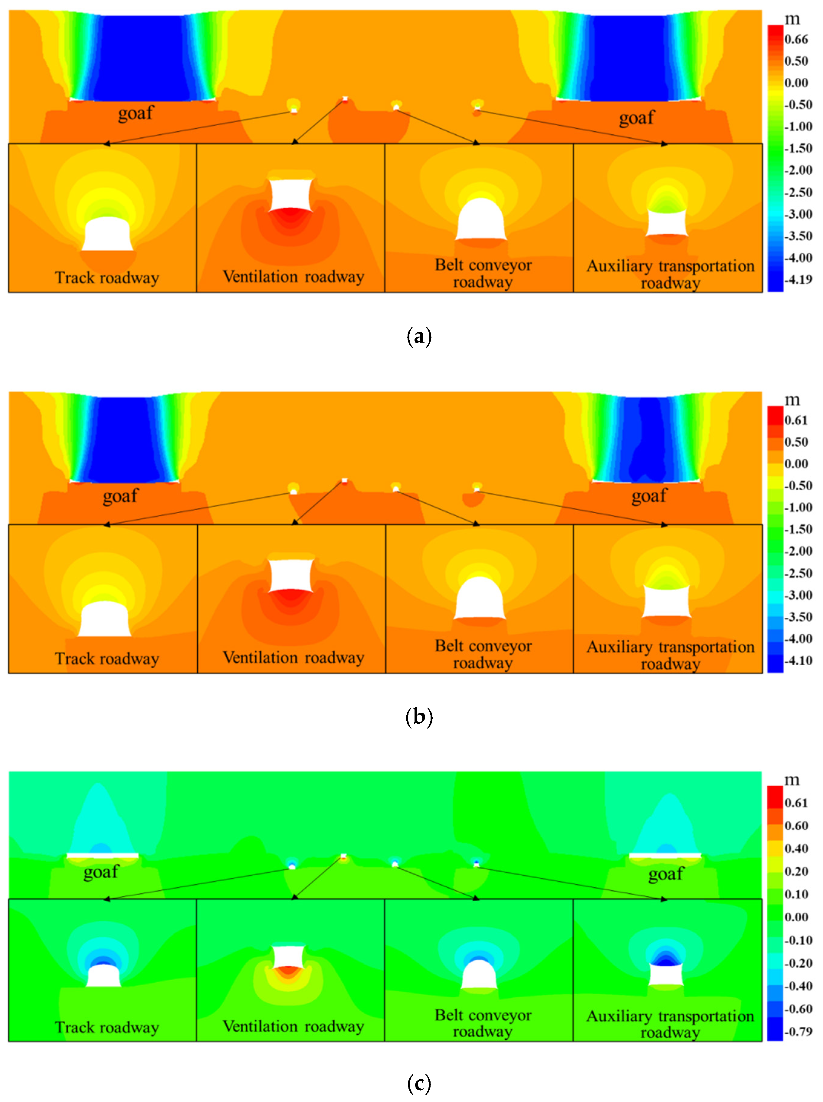
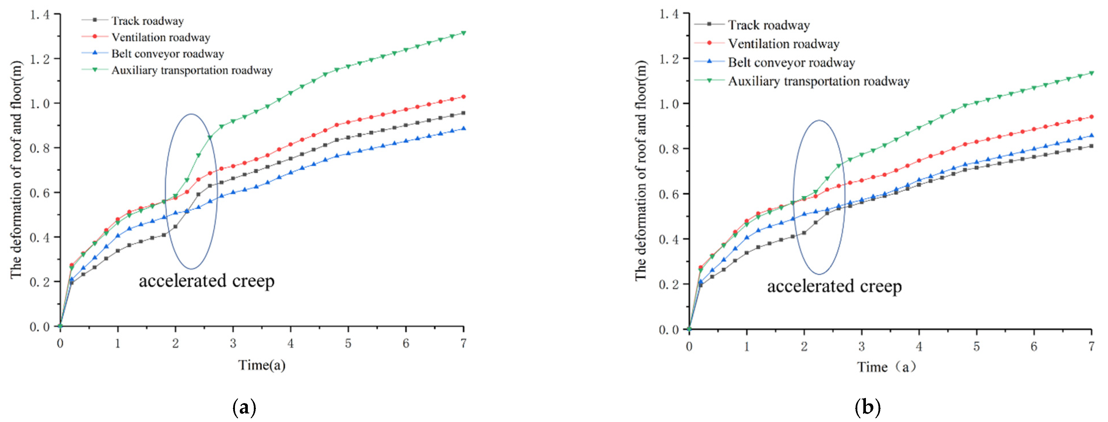
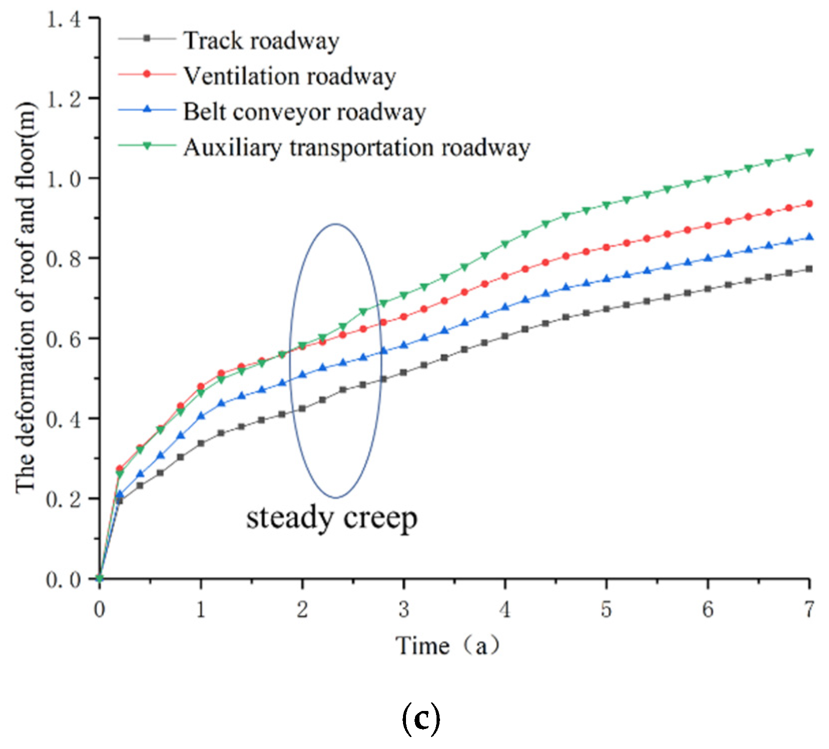
4.3. The Influence of Working Face Rheological Coupling Mining on Deformation Disturbance of Roadway Groups
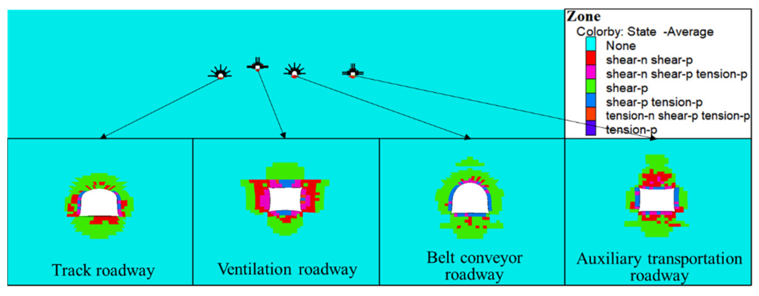
4.4. The Influence of Rheological Coupling Mining of Working Face on Disturbance of Plastic Zone of Roadway Groups
5. Conclusions
Author Contributions
Funding
Institutional Review Board Statement
Informed Consent Statement
Data Availability Statement
Acknowledgments
Conflicts of Interest
References
- Wang, Q.; Gao, H.; Yu, H.; Jiang, B.; Liu, B. Method for Measuring Rock Mass Characteristics and Evaluating the Grouting-Reinforced Effect Based on Digital Drilling. Rock Mech. Rock Eng. 2018, 52, 841–851. [Google Scholar] [CrossRef]
- Sun, Y.; Li, G.; Zhang, J.; Xu, J. Failure Mechanisms of Rheological Coal Roadway. Sustainability 2020, 12, 2885. [Google Scholar] [CrossRef] [Green Version]
- Xiao, C.; Zheng, H.; Hou, X.; Zhang, X. A stability study of goaf based on mechanical properties degradation of rock caused by rheological and disturbing loads. Int. J. Min. Sci. Technol. 2015, 25, 741–747. [Google Scholar] [CrossRef]
- Jia, J.; Yu, F.; Tan, Y.; Gao, X.; Zhang, H. Experimental Investigations on Rheological Properties of Mudstone in Kilometer-Deep Mine. Adv. Civ. Eng. 2021, 2021, 6615379. [Google Scholar] [CrossRef]
- Qu, G.L.; Wang, J.; Liu, G.L. Research on Supporting Theory of Pressure-Bearing Ring and Yield Supporting Technology in Extremely Soft Rock Roadway. Appl. Mech. Mater. 2013, 395, 536–543. [Google Scholar] [CrossRef]
- Lin, H. Study of Soft Rock Roadway Support Technique. Procedia Eng. 2011, 26, 321–326. [Google Scholar] [CrossRef] [Green Version]
- Li, C.L.; Li, Z.Y. Geology Analysis and Support Scheme Design in Soft Rock Coal Mine. Adv. Mater. Res. 2012, 446, 1591–1595. [Google Scholar] [CrossRef]
- Ma, N.J.; Zhao, Z.Q.; Zhao, H.; Jiang, L.S. High Strength Combined Support Technology in Deep High Stress Soft Rock Roadway. Adv. Mater. Res. 2012, 524, 598–603. [Google Scholar] [CrossRef]
- Li, S.C.; Wang, H.T.; Wang, Q.; Jiang, B.; Wang, F.Q.; Guo, N.B.; Liu, W.J.; Ren, Y.X. Failure mechanism of bolting support and high-strength bolt-grouting technology for deep and soft surrounding rock with high stress. J. Cent. South Univ. 2016, 23, 440–448. [Google Scholar] [CrossRef]
- Sun, Y.; Li, G.; Zhang, J.; Qian, D. Stability Control for the Rheological Roadway by a Novel High-Efficiency Jet Grouting Technique in Deep Underground Coal Mines. Sustainability 2019, 11, 6494. [Google Scholar] [CrossRef] [Green Version]
- Chen, Y.; Meng, Q.; Xu, G.; Wu, H.; Zhang, G. Bolt-grouting combined support technology in deep soft rock roadway. Int. J. Min. Sci. Technol. 2016, 26, 777–785. [Google Scholar] [CrossRef]
- He, M.C.; Yand, J.; Qi, G.; Wang, S.R. Optimized design and its application of coupling support for soft rock roadway at great depth. J. Liaoning Tech. Univ. 2007, 1, 40–42. [Google Scholar]
- Li, J. The coal pillar design method for a deep mining roadway based on the shape of the plastic zone in surrounding rocks. Arab. J. Geosci. 2020, 13, 1–12. [Google Scholar] [CrossRef]
- Yankai, R.C.L.K.Z. Study on Surrounding Rock Stability of Long-Span Coal Roadway under Influence of Mining and Support Technology Optimization. In Proceedings of the IOP Conference Series: Earth and Environmental Science, Hefei, China, 19–21 October 2018; p. 012016. [Google Scholar]
- Zhai, C.; Xu, Y.; Xiang, X.; Yu, X.; Zou, Q.; Zhong, C. A novel active prevention technology for borehole instability under the influence of mining activities. J. Nat. Gas Sci. Eng. 2015, 27, 1585–1596. [Google Scholar] [CrossRef]
- Zhan, Q.; Zheng, X.; Du, J.; Xiao, T. Coupling instability mechanism and joint control technology of soft-rock roadway with a buried depth of 1336 m. Rock Mech. Rock Eng. 2020, 53, 2233–2248. [Google Scholar] [CrossRef]
- Li, G.; Sun, Y.; Zhang, J.; Zhang, Q.; Sun, C.; Zhang, S.; Bi, R. Experiment and application of coalcrete on roadway stability: A comparative analysis. Adv. Mater. Sci. Eng. 2020, 2020, 6813095. [Google Scholar] [CrossRef]
- Sun, Y.; Li, G.; Zhang, J. Developing hybrid machine learning models for estimating the unconfined compressive strength of jet grouting composite: A comparative study. Appl. Sci. 2020, 10, 1612. [Google Scholar] [CrossRef]
- Sun, Y.; Li, G.; Zhang, J. Investigation on jet grouting support strategy for controlling time-dependent deformation in the roadway. Energy Sci. Eng. 2020, 8, 2151–2158. [Google Scholar] [CrossRef] [Green Version]
- Yu, W.; Pan, B.; Zhang, F.; Yao, S.; Liu, F. Deformation Characteristics and Determination of Optimum Supporting Time of Alteration Rock Mass in Deep Mine. KSCE J. Civ. Eng. 2019, 23, 4921–4932. [Google Scholar] [CrossRef]
- Wu, K.; Shao, Z.; Qin, S.; Zhao, N.; Chu, Z. An improved non-linear creep model for rock applied to tunnel displacement prediction. Int. J. Appl. Mech. 2021. [Google Scholar] [CrossRef]
- Bondarenko, V.; Hardygora, M.; Symanovych, H.; Sotskov, V.; Snihur, V. Numerical methods of geomechanics tasks solution during coal deposits’ development. Min. Miner. Depos. 2016, 10, 1–12. [Google Scholar] [CrossRef] [Green Version]
- Pongpanya, P.; Sasaoka, T.; Shimada, H.; Hamanaka, A.; Wahyudi, S. Numerical study on effect of longwall mining on stability of main roadway under weak ground conditions in Indonesia. J. Geol. Resour. Eng. 2017, 3, 93–104. [Google Scholar]
- Trigueros, E.; Cánovas, M.; Arzúa, J.; Alcaraz, M. Stability of an abandoned siderite mine: A case study in northern Spain. Open Geosci. 2021, 13, 359–376. [Google Scholar] [CrossRef]
- Sun, Y.; Li, G.; Zhang, J.; Huang, J. Rockburst intensity evaluation by a novel systematic and evolved approach: Machine learning booster and application. Bull. Eng. Geol. Environ. 2021, 80, 8385–8395. [Google Scholar] [CrossRef]
- Eremenko, V.A.; Galchenko, Y.P.; Kosyreva, M.A. Effect of Mining Geometry on Natural Stress Field in Underground Ore Mining with Conventional and Nature-Like Technologies. J. Min. Sci. 2020, 56, 416–425. [Google Scholar] [CrossRef]
- Wen, Z.; Qu, G.; Wen, J.; Shi, Y.; Jia, C. Deformation failure characteristics of coal body and mining induced stress evolution law. Sci. World J. 2014, 2014, 714507. [Google Scholar] [CrossRef] [PubMed]
- Wang, H.; Jiang, Y.; Xue, S.; Shen, B.; Wang, C.; Lv, J.; Yang, T. Assessment of excavation damaged zone around roadways under dynamic pressure induced by an active mining process. Int. J. Rock Mech. Min. Sci. 2015, 77, 265–277. [Google Scholar] [CrossRef]
- Wang, H.; Shi, R.; Lu, C.; Jiang, Y.; Deng, D.; Zhang, D. Investigation of sudden faults instability induced by coal mining. Saf. Sci. 2019, 115, 256–264. [Google Scholar] [CrossRef]
- Zhu, D.; Tu, S.; Tu, H.; Yang, Z. Mechanisms of support failure and prevention measures under double-layer room mining gobs—A case study: Shigetai coal mine. Int. J. Min. Sci. Technol. 2019, 29, 955–962. [Google Scholar] [CrossRef]
- Wang, F.; Xu, J.; Xie, J.; Li, Z.; Guo, J. Mechanisms influencing the lateral roof roadway deformation by mining-induced fault population activation: A case study. Int. J. Oil Gas Coal Technol. 2016, 11, 411–428. [Google Scholar] [CrossRef]
- Wang, Q.; He, M.; Li, S.; Jiang, Z.; Wang, Y.; Qin, Q.; Jiang, B. Comparative study of model tests on automatically formed roadway and gob-side entry driving in deep coal mines. Int. J. Min. Sci. Technol. 2021, 31, 591–601. [Google Scholar] [CrossRef]
- Li, G.; Ma, F.; Guo, J.; Zhao, H.; Liu, G. Study on deformation failure mechanism and support technology of deep soft rock roadway. Eng. Geol. 2020, 264, 105262. [Google Scholar] [CrossRef]
- Sun, Y.; Li, G.; Zhang, J.; Sun, J.; Huang, J.; Taherdangkoo, R. New Insights of Grouting in Coal Mass: From Small-Scale Experiments to Microstructures. Sustainability 2021, 13, 9315. [Google Scholar] [CrossRef]
- Sun, Y.; Zhang, J.; Li, G.; Wang, Y.; Sun, J.; Jiang, C. Optimized neural network using beetle antennae search for predicting the unconfined compressive strength of jet grouting coalcretes. Int. J. Numer. Anal. Methods Geomech. 2019, 43, 801–813. [Google Scholar] [CrossRef]
- Doan, D.V.; Zhao, H.C.; Cao, J.; Yong, C.; Meng, W. Control technology for soft rock roadway in inclined coal seam: A case study in Nui Beo mine, Quang Ninh, Vietnam. Int. J. 2018, 14, 175–182. [Google Scholar] [CrossRef]
- Piotr, M.; Łukasz, O.; Piotr, B. Modelling the small throw fault effect on the stability of a mining roadway and its verification by in situ investigation. Energies 2017, 10, 2082. [Google Scholar] [CrossRef] [Green Version]
- Shiliang, L.; Caigen, W. Strata pressure law for roadway in soft rocks and relationship between support and surrounding rock. In Geotechnical Instrumentation and Monitoring in Open Pit and Underground Mining; CRC Press: Boca Raton, FL, USA, 2020; pp. 339–344. [Google Scholar]
- Xie, S.; Pan, H.; Zeng, J.; Wang, E.; Chen, D.; Zhang, T.; Peng, X.; Yang, J.; Chen, F.; Qiao, S. A case study on control technology of surrounding rock of a large section chamber under a 1200-m deep goaf in Xingdong coal mine, China. Eng. Fail. Anal. 2019, 104, 112–125. [Google Scholar] [CrossRef]
- Wang, H.; Zheng, P.Q.; Zhao, W.J.; Tian, H.M. Application of a combined supporting technology with U-shaped steel support and anchor-grouting to surrounding soft rock reinforcement in roadway. J. Cent. South Univ. 2018, 25, 1240–1250. [Google Scholar] [CrossRef]
- Chakravarthi, S.S.; Kassam, A.B.; Fukui, M.B.; Monroy-Sosa, A.; Rothong, N.; Cunningham, J.; Jennings, J.E.; Guenther, N.; Connelly, J.; Kaemmerer, T.; et al. Awake Surgical Management of Third Ventricular Tumors: A Preliminary Safety, Feasibility, and Clinical Applications Study. Geofluids 2019, 17, 208–226. [Google Scholar] [CrossRef]


| Lithology | Density kg/m3 | Bulk Modulus/GPa | Shear Modulus/GPa | Cohesion/MPa | Friction Angle/° | Tensile Strength/MPa |
|---|---|---|---|---|---|---|
| Gritstone | 2450 | 34.37 | 24.71 | 9.81 | 45 | 10.51 |
| Fine grained sandstone | 2600 | 21.7 | 15.6 | 5.72 | 38 | 7.44 |
| Medium sandstone | 2550 | 30.14 | 21.67 | 7.30 | 41 | 8.21 |
| Siltstone | 2650 | 17.47 | 12.56 | 4.12 | 32 | 2.94 |
| Coal | 1450 | 0.55 | 0.33 | 2.45 | 22 | 0.24 |
| Mudstone | 2250 | 7.11 | 3.86 | 3.43 | 35 | 0.98 |
| Fine siltstone | 2620 | 19.00 | 14.08 | 4.92 | 34 | 5.19 |
| GK/Pa | GM/Pa | NK/Pa.s | NM/Pa.s |
|---|---|---|---|
| 1.38 × 10⁸ | 2.2 × 10⁸ | 2 × 10¹⁸ | 15× 1015 |
| Expansion Depth | ||||
|---|---|---|---|---|
| Distance from Stoping Line /m | Track Roadway | Ventilation Roadway | Belt Conveyor Roadway | Auxiliary Transportation Roadway |
| Unmined | 4524 | 6026 | 6149 | 7234 |
| 50 | 4718 | 6282 | 6391 | 7760 |
| 75 | 4670 | 6211 | 6366 | 7569 |
| 100 | 4655 | 6209 | 6373 | 7390 |
| Expansion Depth | ||||
|---|---|---|---|---|
| Distance from Stoping Line /m | Track Roadway | Ventilation Roadway | Belt Conveyor Roadway | Auxiliary Transportation Roadway |
| Unmined | 3839 | 6294 | 4097 | 3239 |
| 50 | 4628 | 6345 | 4259 | 4578 |
| 75 | 4108 | 6337 | 4244 | 3410 |
| 100 | 4077 | 6336 | 4251 | 3392 |
Publisher’s Note: MDPI stays neutral with regard to jurisdictional claims in published maps and institutional affiliations. |
© 2021 by the authors. Licensee MDPI, Basel, Switzerland. This article is an open access article distributed under the terms and conditions of the Creative Commons Attribution (CC BY) license (https://creativecommons.org/licenses/by/4.0/).
Share and Cite
Yang, S.; Li, G.; Bi, R.; Yao, B.; Feng, R.; Sun, Y. The Stability of Roadway Groups under Rheology Coupling Mining Disturbance. Sustainability 2021, 13, 12300. https://doi.org/10.3390/su132112300
Yang S, Li G, Bi R, Yao B, Feng R, Sun Y. The Stability of Roadway Groups under Rheology Coupling Mining Disturbance. Sustainability. 2021; 13(21):12300. https://doi.org/10.3390/su132112300
Chicago/Turabian StyleYang, Sen, Guichen Li, Ruiyang Bi, Bicheng Yao, Ruiguang Feng, and Yuantian Sun. 2021. "The Stability of Roadway Groups under Rheology Coupling Mining Disturbance" Sustainability 13, no. 21: 12300. https://doi.org/10.3390/su132112300