Article

Experimental Study on Crack Propagation of Rock by Blasting under Bidirectional Equal Confining Pressure Load

1
School of Civil Engineering and Architecture, Anhui University of Science and Technology, Huainan 232001, China
2
Key Laboratory of Mining Response and Disaster Prevention and Control in Deep Coal Mine, Anhui University of Science and Technology, Huainan 232001, China
3
School of Architecture and Art, Huainan United University, Huainan 232001, China
*
Author to whom correspondence should be addressed.
Sustainability 2021, 13(21), 12093; https://doi.org/10.3390/su132112093
Submission received: 2 September 2021 / Revised: 18 October 2021 / Accepted: 26 October 2021 / Published: 2 November 2021
(This article belongs to the Special Issue Advances in Rock Mechanics and Geotechnical Engineering)

Abstract

:
Rock blasting during tunneling has shown that the rock failure in high in situ stress environments is different from that in low in situ stress conditions or with a shallow rock mass. In particular, the propagation direction of the main crack induced by blasting is greatly affected by the in situ stresses. In order to study the law of crack propagation in rock during blasting under the conditions of an initial in situ stress, a transparent material that conformed to the mechanical properties of hard rock was used to carry out a similar model rock blasting test, under a unidirectional load. The results show that initial stress has a great influence on the propagation number, length, and direction of the main radial cracks. The specific performances were as follows: under the action of an equal confining pressure load, the longest main radial crack in the model specimen propagated along the diagonal direction, and the number and length of the main radial cracks propagated decreased with the gradual increase of confining pressure stress; in addition, the diameter of the circumferential cracks also decreased with the increase of stress, and there was a negative correlation between them. In view of the phenomenon where the longest main radial crack propagated along the diagonal direction in the model test, a mechanical model was established in this study to explain this process. This is of practical significance for understanding the mechanism of rock fracture when blasting with high in situ stresses.

1. Introduction

With the increasing demand for natural resources, surface and subsurface mines are becoming depleted and underground mines continue to progress to deeper levels. The depths of many mines around the world are more than 1000 m below the surface, and the gold mine in Vaal Reefs, South Africa has reached the world’s greatest mining depth, of 4800 m. This increasing mining depth leads to increasing in situ stress in the surrounding rock of roadways, which brings a series of new problems for roadway excavation and support [1,2].
Engineering evaluations of blasting operations carried out in a deep rock mass showed that the fracture failure in deep rock was different from that in a shallow rock mass. However, the influence of in situ stress was not taken into account in the design of the existing blasting parameters for roadway excavation, which resulted in low blasting efficiencies for the roadway, thus affecting the speed and efficiency of roadway construction [3]. In addition, in the process of the blasting construction of a cavern for a underground hydropower station, it was found that the in situ rock stress field in the stratum had an obvious influence on the design of the blasting parameters [4,5,6]. Under a condition of low in situ stress (horizontal in situ stress < 10 MPa), whether using smooth blasting or pre-splitting blasting, an ideal blasting effect can be obtained. However, in areas of high in situ stress (horizontal in situ stress > 10 MPa), the appropriate blasting technology (pre-splitting blasting or smooth blasting) and sequence need to be considered comprehensively, according to the actual situation [7]. Thus, it can be seen that the effects of in situ stress on rock blasting cannot be ignored [8,9,10,11,12,13,14], and failures in deep rock mass are the result of the joint action of high in situ stress and as explosive impact load; that is, the superposition action of the initial static stress field and the explosive dynamic load.
Gao et al. [15] investigated the mechanism of controlled blasting under high in situ stress by using a dynamic photo-elastic experimental system with initial stress loading. It was concluded from their research results that (1) the direction without initial stress or with a small initial stress is the best direction for blasting deformation and compressive energy release; (2) the stress field superposed by the initial static stress field and the explosive dynamic load produces tensile stress, initially in the direction of the smaller static stress; (3) the stress boundary restrains the occurrence and development of reflected tensile waves to a certain extent, and the failure of the medium is mainly caused by extrusion and compression shear, which indicates that a blasting mechanism based on free surface reflection tension is not suitable for controlled blasting under high in situ conditions.
Existing studies have shown that the initial in situ stress has an obvious “suppression” effect on the development of blast-induced cracks and that the blast-induced cracks preferentially propagate in the direction of the maximum principal stress in a static stress field [16]. When the direction of cracks is perpendicular to the direction of the static compressive stress, the static compressive stress field hinders the propagation of cracks. However, when the cracks deflect towards or coincide with the direction of the static stress field, the hindrance of the static compressive stress field on the crack growth is greatly reduced [17]. According to research by Yang [18], this is because the initial compressive stress field reduces the stress concentration at the crack tip, hinders the crack growth, and thus shortens the propagation distance of the main blast-induced crack, which appears to have a ‘suppression’ effect on the crack.
In experiments and production practice, it is found that hole blasting in a medium with dynamic and static stress fields presents various phenomena of preferential crack initiation, good blasting effects, and low explosive consumption, which was described as a ‘waveguide effect’ by Zhang [19]. He suggested that the dynamic response of a rock mass must be changed due to the existence of complex in situ stress in the rock mass, and the superposition of a blasting stress wave and in situ stress conforms to the law of phase strength and phase weakness; that is, being strong in the same phase and weak in the contrary phase. In this regard, Xiao [20] proposed a principle, whereby the initial stress field has a ‘guiding effect’ on the propagation of cracks. According to this theory, the huge pressure generated by an explosion initially causes compressive stress waves in the rock. Then, the stress state in the hole wall propagates outward in the form of a cylindrical wave and at the same time produces tensile stress in the direction tangential to the hole wall. When the in situ stress is large enough, and the direction of principal stress is consistent with that of explosion stress wave, the explosion stress wave will collide with, and be superimposed on, the in situ stress, and tensile stress will be generated in the direction tangential to the collision. When the resultant tensile stress exceeds the tensile strength of the rock, the rock will crack along the direction of the principal stress.
In summary, existing studies only employed a qualitative analysis of the propagation direction of a blast-induced main crack in rock with an initial stress, which leads to their limited guidance value for actual blasting engineering in deep rock masses. In addition, there are few studies on the effect of in situ stress on the circumferential fractured zone in the central blasting area. To this end, blasting model tests of transparent rock under the action of confining pressure were carried out in this study, to study the mechanism of in situ stress in crack propagation by blasting and reveal the law of the effects of in situ stress on the direction and length of crack propagation when blasting, as well as the diameter of the circumferential fractured zone in the central blasting area.

2. Materials and Methods

2.1. Test Device

A self-developed test device with a plane stress loading system, data measurement system, and high-speed photography system was used to simulate the in situ stress constraint in a deep rock mass. The device includes a stress loading platform, oil pressure station, high-speed camera suspension, etc., as shown in Figure 1.
The maximum size of model specimen applied to the stress loading platform was 500 × 500 × 100 mm (length × width × height). The rated power and extreme power of the oil pressure station used for the loading platform were 5 MPa and 7 MPa, respectively, and the piston area of a single oil cylinder was 7.065 cm2. If the device is used to load a model specimen with a size of 300 × 300 × 20 mm, the rated load concentration and ultimate load concentration that can be reached inside the specimen are 1.18 Mpa and 1.65 Mpa, respectively, which basically satisfies the uniform conditions of the stress field in the model.

2.2. Similarity Coefficient

The deep roadway project of the Dingji Coal Mine, in the Huainan mining area, was used as the prototype for the model test. The in situ stress field in this mining area is mainly dominated by horizontal tectonic stress [21]. The cross-sectional shape of the roadway is a semicircular arch, and the cross-section size is 5000 × 3880 mm, while the depth of the roadway is 910 m. The roadway is mainly located in a stratum of medium sandstone and siltstone, and the physical and mechanical parameters of the protolith are shown in Table 1.
At present, the material most commonly used in similarity model experiments of rock blasting is cement mortar [22]. However, it is not transparent, which led to the problem that, after the test, the cracks in the model made of cement mortar could not be seen. Therefore, a kind of transparent hard rock-like material, which could replace the existing model material to solve the above problem, was used in this study. This transparent hard rock-like material was made of a mixture of rosin-saturated solution (RSS), epoxy resin (ER), and curing agent (CA), and its physical and mechanical properties have been proven, through relevant tests, to be similar to those of hard rock [23]. The basic physical and mechanical parameters are shown in detail in Table 2.
In similar systems, the ratio of the similar physical quantities is called the similarity ratio (or called similarity constant and similarity coefficient); that is, ‘prototype physical quantity (P)/model physical quantity (M) = similarity ratio (α)’ [24,25]. According to the balance equation, geometry equation, physical equation, stress boundary condition, and displacement boundary condition of the prototype and model (process omitted), the similarity relation between the various physical quantities of the model test can be obtained as
{ α ν = 1 ,   α ε = 1 ,   α φ = 1 α δ = α L α X = α Y = α Z = α γ α σ = α L · α γ α σ c = α σ t = α E = α C = α σ α T = α L
According to the bulk density of the model material and prototype material, the similarity coefficient for the bulk density can be calculated as α γ = 2.2. The similarity scale of the model selected for the test was 1:16.7 in this study. Hence, it could be calculated using the above formula as: stress similarity coefficient α σ = 36.7, elastic modulus similarity coefficient α E = 36.7, cohesion similarity coefficient α C = 36.7, time similarity coefficient α T = 4.15, strain similarity coefficient α ε = 1, Poisson’s ratio similarity coefficient α ν = 1, and internal friction angle similarity coefficient α φ = 1.

2.3. Blasting Charge

Many engineering works on rock blasting show that the explosion shock wave acts directly on the hole wall of the blasthole when using a coupling charge, which forms into a large-scale crushed zone near the blasthole in the rock mass. In the crushing circle, the rock fragmentation absorbs most of the energy of the explosion shock wave, resulting in the rapid attenuation of energy. However, the impact pressure of the explosion shock wave on the hole wall is smaller when using an uncoupled charge, which makes the radius of the crushing circle shrink. Therefore, a stress wave with a smaller attenuation can act on the fracture circle of the rock mass for a longer time, and the effect on the production of cracks is good. It has been shown that using an uncoupled charge in rock blasting can enlarge the range of the fractured zone and make full use of the explosive energy [26].
The method of uncoupled charges is used in model tests of rock blasting. We designed the diameter of the blasthole, diameter for charging, and height for charging as 4 mm, 3 mm, and 20 mm, respectively. In view of the small amount of explosives used in the model test, a type of relatively safe and stable small detonator was selected as the explosive in the test, and its main component was DDNP (Table 3). According to the dynamic similarity criterion [27], it can be concluded that the relationship between the similarity explosive and the prototype explosive is satisfied with C ρ C D = 1 ( C ρ is the density ratio of the prototype explosive to the model explosive, and C D is the detonation velocity ratio of the prototype explosive to the model explosive). The prototype explosive was a three-level permissible water-gel explosive for coal mining, with a density of 1.1 g/cm3 and a detonation speed of 3600 m/s. The model explosive was DDNP in bulk, with a density of about 0.7 g/cm3 and a detonation speed of 5400 m/s. This was obtained through calculating that C ρ C D = 1.047, which basically meets the principle of a ‘similar blasting energy of explosives’.
The blasthole for charging was located in the center of the specimen, and the two ends were bonded with 1 mm thick plastic discs, which were used for fixing the special small detonator. The detailed charging structure is shown in Figure 2.

2.4. Test Scheme

The uniaxial compressive strength (UCS) of the materials, value for the confining pressure, and usage of explosive required by the model test were calculated according to similarity theory. Before the formal model blasting test, a pre-blasting model test was carried out. The test results showed that the specimens were completely broken, due to the low UCS of the materials, which is unfavorable for studying the law of crack propagation of a specimen after blasting. Therefore, on the basis of theoretical calculation, and combined with the results of the pre-blasting test, the parameters of the blasting model were adjusted appropriately; and the parameters of the model specimens are shown in Table 4. The production method for the model specimens referred to the study by Ge [23].
It was known that C σ = 36.7 (stress similarity coefficient), σ v = γ H (vertical stress), and we also assumed that   σ h a v = σ v (average horizontal stress). Therefore, if the buried depth of the simulated rock mass designated in the test was from 0 m to 1300 m, the corresponding loading stress values of the simulated confining pressure of the vertical and horizontal would be from 0 MPa to 0.955 MPa. The six groups of loading schemes used in the actual model test are shown in Table 5.

2.5. Production Method

Taking the plate model specimen as an example [23], the detailed production steps were as follows:
(1) Pre-made solution. Unlike epoxy resins and curing agents, RSS cannot be purchased directly and needs to be made. First, the optimal rosin blocks were broken down into powders, which were screened through a 100-mesh screen. Then, a 100-mesh rosin powder was melted into an appropriate amount of anhydrous alcohol solution, until the solution reached a saturated state.
(2) Sticking film in the mold. From the exploratory test, it was found that pouring the mixed solution directly into the mold made it difficult to disassemble the mold, so it was necessary to pretreat the mold before pouring. First, a thin layer of Vaseline was applied to the surface of the mold, and then an anti-stick film was applied to the surface.
(3) Pouring specimen. First, the epoxy resin, curing agent, and RSS were weighed according to the designed experimental proportions and placed in a beaker. Then, the epoxy resin and curing agent were heated in an oven to 50 °C, and the RSS was heated in a water bath to 50 °C. When all the bubbles in the epoxy resin and curing agent were removed, they were mixed and stirred evenly. At this time, bubbles inevitably appeared again in the mixed solution, so they were heated in an oven at 50 °C until the bubbles were removed. Finally, the RSS was taken out from the water bath and poured into the epoxy resin system. After the mixture was stirred evenly, it was poured into the mold. It was concluded after many experiments that no bubbles will appear, as long as the mixture of three solutions is stirred slowly and uniformly when the preheated RSS is mixed with the non-bubbled thermal epoxy resin system.
(4) Maintenance and polishing of the specimen. The mold filled with the resin mixture solution was gently placed in a room at a constant temperature for maintenance. After the epoxy resin had cured completely, the mold was removed and the uneven areas of the specimen were polished with sandpaper or a small grinder.
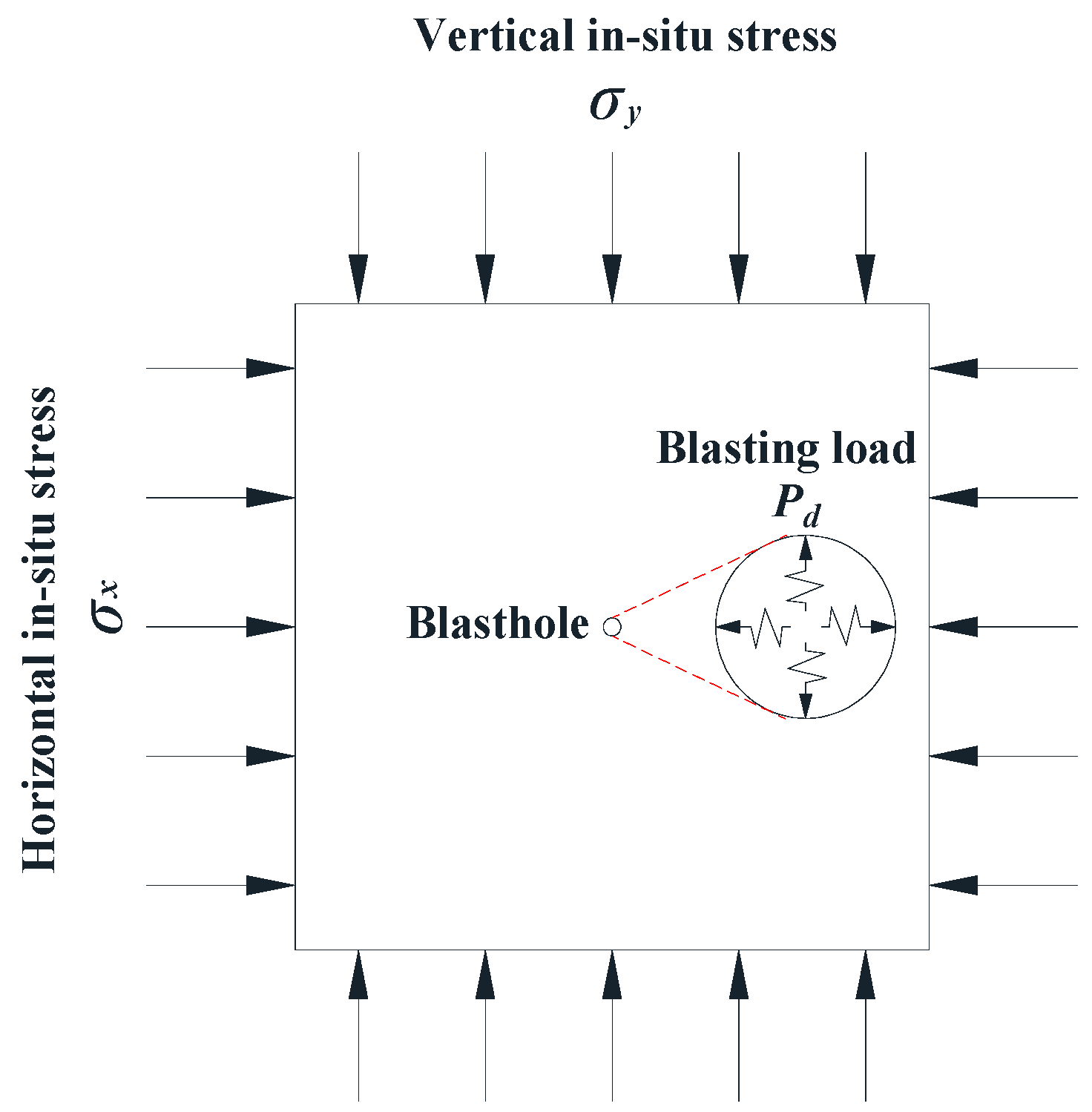
3. Results and Analysis

3.1. Results of Blasting Model Test

The propagation of cracks in the specimens after blasting is shown in Figure 3. A relevant supplementary explanation is made for the cracks in Figure 3, before analyzing the law of crack propagation in the model specimen. It can be seen from Figure 3b–f that the cracks generated in the model specimens all reached the boundary of the specimens. This is because the cracks generated by the explosion load continued to propagate in different directions after the static confining pressure was unloaded. In Figure 3, the main radial cracks are marked by yellow lines, and the propagation range of circumferential cracks is marked by blue lines.
According to the fragmentation mechanism of rock blasting, for a certain amount of charge, if the minimum resistance line exceeds a certain threshold (called the critical resistance line, Wc), there will be no blasting signs on the free surface after the charge explosion. That is, the blasting only occurs inside the rock mass and fails to reach the free surface, which is equivalent to charge blasting in an infinite medium. This action is called internal action. When the charge only acts internally, the explosion action zone can be roughly divided into a crushed zone, fractured zone, and vibrated zone [28,29], as shown in Figure 4.
Under the action of an explosion shock wave and high temperature and pressure gas, rock near the blasthole will be crushed and produce a large plastic deformation, forming a crushed zone.
When the shock wave propagates to a certain distance, it becomes a compressive stress wave, due to its energy attenuation [30]. At this time, the peak value of the radial stress of the compressive stress wave is less than the value of the dynamic compressive strength of the rock, and it cannot cause the crushing failure of the rock, but instead the radial displacement of rock. Compressive stress and compression deformation occur in the radial direction, while tensile stress and tensile deformation occur in the tangential direction. When the value of the tensile stress is more than that of the dynamic tensile strength, cracks are generated along the radial direction of the blasthole. The air wedge effect of explosive gas makes the crack expand and extend. When the stress wave and the pressure of the explosive gas are further attenuated, the energy accumulated by the radial compression of the rock will be released and transformed into an unloading wave towards the source of explosion, forming radial tensile stress. This causes the rock to be pulled apart by the radial tensile stress, forming tangential cracks. It can be concluded that the fractured zone is mainly formed by tensile failure.
In the vibrated zone [31], the original structure of the medium is not damaged, but only elastic deformation is produced. The vibration strength gradually weakens with the increase of distance through the medium from the explosion center, until it completely disappears.
Figure 3a shows the crack propagation of the post-explosion model specimen under the condition of no initial stress. It can be observed that a crushed zone, fractured zone, and vibrated zone were formed in the post-explosion specimen, which conforms to the fracture pattern of single-hole charge blasting in an infinite medium.
Figure 3b–f shows the crack propagation of a post-explosion model specimen under an equal confining pressure load. Compared with without a confining pressure, the crack propagation of the model specimens under a bi-directional equal confining pressure changed greatly, including in the number, length, and propagation direction of the main radial cracks in the cracked zone. If the post-explosion model specimen is divided into several areas (Figure 5), it can be clearly seen from the test results that the longest main radial cracks are distributed in four areas A, B, C, and D, and only a few radial cracks developed along the directions of σ v or σ h .
In the engineering of rock excavation by blasting, smooth blasting or presplitting blasting technology is often used for the boundary excavation, so as to reduce the damage from blasting to the surrounding rock and the reduction of its stability. Since the range of the fractured zone is an important reference basis for the design of controlled blasting parameters, this study focused on quantitatively describing the variation of crack propagation in the fractured zone of model specimens with the size of the applied load; and the main radial cracks of the post-explosion specimens are marked, as shown in Figure 6.
As shown in Figure 6, the post-explosion specimens were divided into a compression crushed zone (I), fractured zone (II and III), and vibrated zone (IV). With the increase of confining stress load on the model, the range of the fractured zone decreased greatly, the range of the vibrated zone increased, and only the range of the crushed zone did not change significantly. This study focuses on the propagation of the fractured zone, and Part II of the fractured zone was analyzed first.

3.2. Crack Propagation Analysis

3.2.1. The Influence of Initial Stress on the Scope of the Circumferential Fractured Zone

As shown in Figure 3, the model specimens had the characteristics of geometric symmetry and mechanical symmetry. In theory, the diameter of the circumferential fracture along the direction σ v is the same as that along the direction σ h , and the diameters of the circumferential fractures along the two diagonals (the angle between diagonal and σ v or σ h is 45 °C) are also equal. The measurement results of the diameters of the circumferential cracks in the post-explosion specimens are shown in Table 6.
It can be seen from Table 6 that the measured diameter of the circumferential fracture along the direction σ v was not equal to that along the direction σ h ; whereas, these two values should be equal according to the symmetry principle. Similarly, the diameters of circumferential fracture along the diagonal direction were also not equal. Therefore, the average diameters were used to characterize the propagation range of the circumferential crack in the post-explosion specimen. The relationship between the average diameters of the circumferential crack and the stress of the confining pressure is shown in Figure 7.
As can be seen from Figure 7, the average diameters along the diagonal direction of the circumferential cracks were significantly smaller than those along the σ v and σ h directions, and both of them gradually decreased with the increase of initial stress, which was obviously ‘constrained’ by the confining pressure stress. As the model specimens were compressed by the initial stress, the dynamic compressive strength of medium inside the specimens increased, resulting in the weakening of the loading and unloading effect of compressive stress wave on the medium around the blasthole, and finally it resulted that the diameter of the circumferential crack decreased with the increase of stress.
Furthermore, by fitting the data points in Table 6, the relationship between the stress of the confining pressure and the diameter of the circumferential crack can be obtained, as follows:
D 1 = 11.037 2.451 e ( C p 1.261 )   ( R 2 = 0.942 ,   C p ( 0.3 , 0.96 ) MPa )
D 2 = 5.280 + 7.949 e ( C p 0.1995 )   ( R 2 = 0.964 ,   C p ( 0.3 , 0.96 ) MPa )
where D1 is the mean diameter of the circumferential crack along the horizontal and vertical direction; D2 is the mean diameter of the circumferential crack along the direction of the two diagonals.

3.2.2. The Influence of Initial Stress on the Propagation Length and Direction of the Main Radial Crack

As shown in Figure 6, the number and length of the main radial cracks decreased with the change of load applied to specimen TSG-0~5. In addition, the propagation direction of the main radial crack also changed. In particular, the longest main radial crack propagated along the diagonal direction (namely, the angle between the propagation direction and horizontal or vertical direction is 45°), which made the confining stress have a ‘guiding’ effect on the propagation direction of the main radial cracks. This is consistent with the conclusion that many researchers have reached [32,33], but so far researchers have not provided a convincing explanation of the mechanism of this phenomenon. In this part of the discussion of this study, a mechanical model will be established with knowledge of the elasticity, explosion mechanics, and stress wave theory, in order to analyze the failure mechanism.
With a further increase of confining pressure stress applied to the model specimens, the propagation lengths of the main radial cracks tended to be the same, which were close to the diameters of the circumferential cracks. At the same time, the propagation direction presented diversification; that is, the propagation direction was evenly distributed along the vertical, horizontal, and diagonal lines, such as in the main cracks in post-specimens TSG-4 and TSG-5.
According to the mechanism of rock fragmentation by blasting, the fractured zone is mainly formed by tensile damage from the tensile stress wave. Then, with a further increase of confining pressure, the tensile strength of the specimens is further improved, resulting in it becoming difficult to produce rock tensile damage along all directions with the tensile stress wave. Even along the diagonal direction, it is difficult to produce tensile failure in rocks. Therefore, the ‘guiding’ effect of the confining pressure stress on the propagation of the longest main radial crack is weakened.
In order to study the variation law of the length of the main radial cracks with the initial stress, a ruler was used to measure the length of the radial cracks in the post-explosion model specimens, and the results are shown in Table 7.
By taking the confining load as the X-axis and the crack length as the Y-axis, the relationship between crack propagation and initial stress was established, as shown in Figure 8.
It can be seen from Figure 8 that the length of the longest main radial crack and average length of the main radial cracks decreased gradually with the increase of initial stress. Furthermore, by fitting the data points in Figure 8, it can be shown that the relationship between the propagation length of the longest main radial crack and the initial stress conformed to the following formula.
L l g = 18.598 32.54 C p + 35.893 C p 2 19.4 C p 3     ( R 2 = 0.978 ,   C p ( 0.0.96 ) MPa )
And the relationship between average propagation length of the main radial cracks and the stress of confining pressure is as follows.
L a v g = 17.27 39.66 C p + 52.55 C p 2 27.68 C p 3     ( R 2 = 0.988 ,   C p ( 0.0.96 ) MPa )
Equations (4) and (5) indicate that the length of the main radial cracks under a bidirectional confining pressure load depended on the initial stress, and there was a cubic function relationship between the two. In this way, this can provide a reference for the design of controlled blasting parameters in a deep rock mass.

4. Discussion

A deep rock mass is mainly subjected to vertical and horizontal in situ stresses [34,35]. When a rock in a state of static in situ stresses is subjected to the dynamic loading of an explosion, it will start to be damaged at a certain time. In this process, the effect of in situ stress on the rock is usually regarded as quasi-static loading. Therefore, the stress state of deep rock mass engineering can be simulated using a combination of dynamic and static loading (shown in Figure 9). It is assumed that the initial stress of the rock mass in the vertical direction is σ y , the initial stress in the horizontal direction is σ x , the internal explosion load is P d , and the compressive strength and tensile strength of the rock are σ c , σ t , respectively.
The fractured zone is the main area of rock failure in engineering blasting [36], and its failure range is much larger than that of the compression crushed zone. Moreover, the influence of the initial stress on the blast-induced compression crushed zone in rock is relatively small; therefore, this study discussed the influence of initial in situ stress on the crack propagation in the blast-induced fractured zone in rock. According to the stress mode of an engineering rock mass, the influence of initial stress on the crack propagation from rock blasting can be analyzed in different cases; that is, the rock mass is subjected to unequal confining pressure loads and equal confining pressure loads.
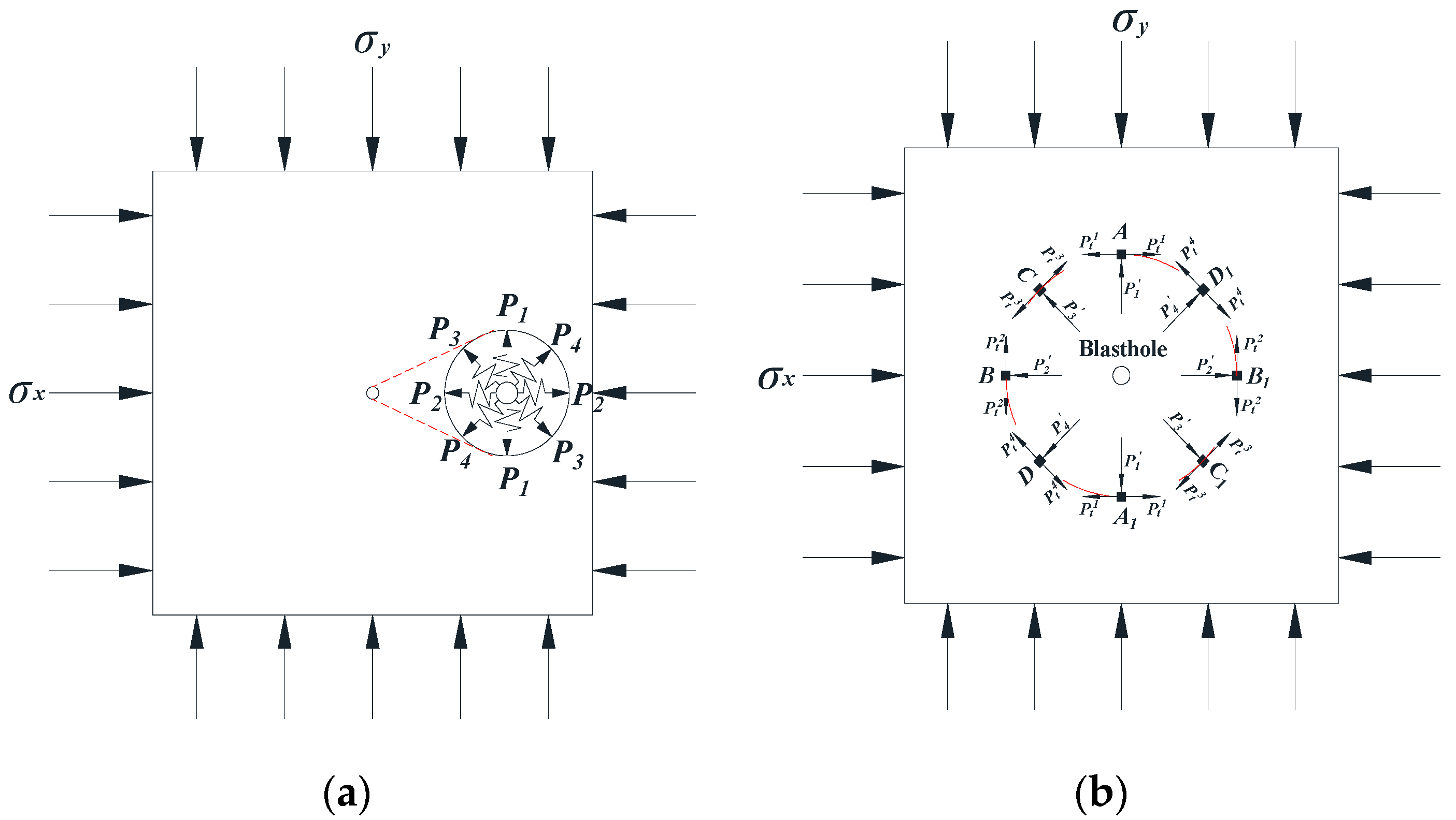
It is supposed that the in situ stress applied to the model is σ x = σ y     0. In this case, the force model can be simplified, as shown in Figure 10a, and the explosion load is described by P 1 , P 2 , P 3 , and P 4 ( P 1 = P 2 = P 3 = P 4 ). Blasting theory indicates that the blast shock wave on the hole wall is attenuated into a stress wave when it propagates to the middle zone (fractured zone) of the blasting. The stress wave in the model, within the same radius of the fractured zone (the crack is still in propagation), at a certain moment is described by P 1 , P 2 , P 3 , and P 4 ( P 1 = P 2 = P 3 = P 4 ), and a micro point taken from each of the eight different directions can be denoted as A, A1, B, B1, C, C1, D, and D1. The circumferential tensile stresses at the above eight points are described by P t 1 , P t 2 , P t 3 , and P t 4 . Meanwhile, it is assumed that P t 1 = P t 2 = P t 3 = P t 4 . In this way, the dynamic load is also simplified to the static load (as shown in 
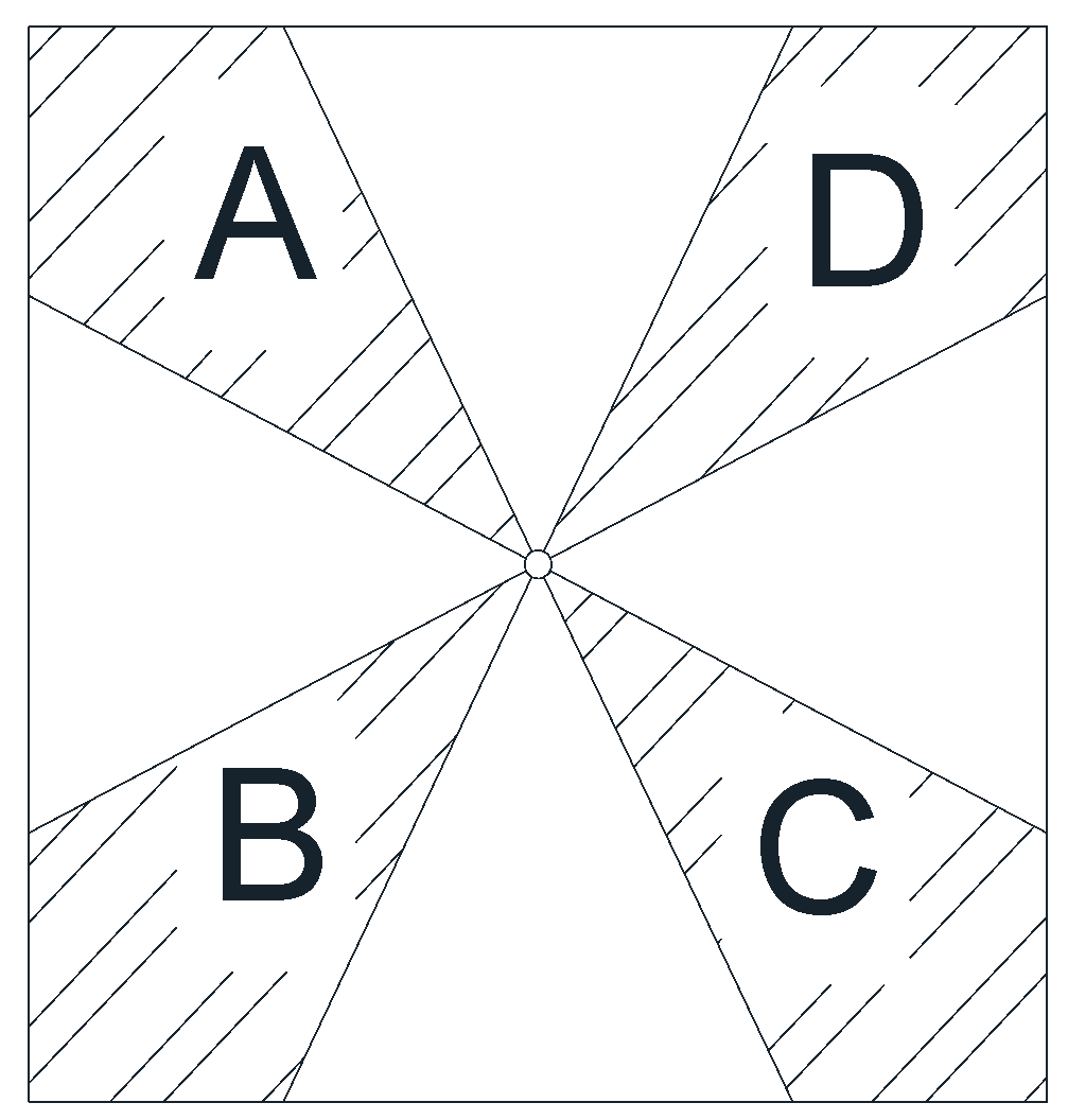
Figure 10b). In this case, stress analysis can be carried out according to the plane stress problem, in the theory of elastic mechanics.
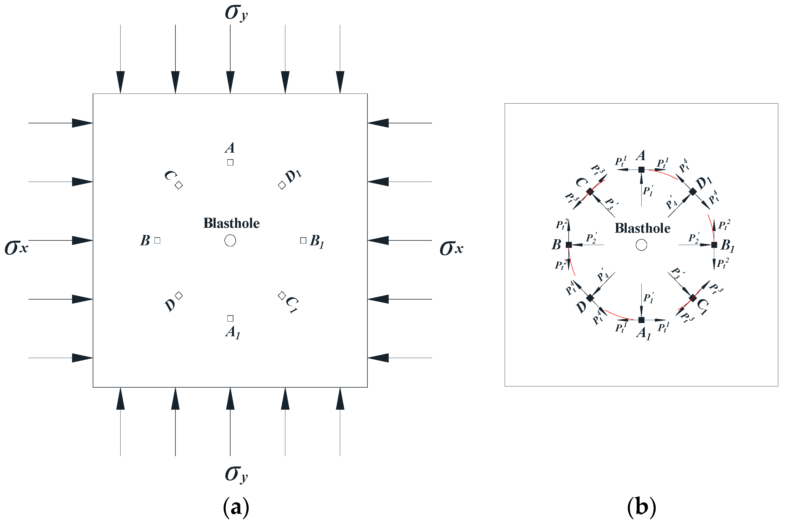
Furthermore, the force model of a rock mass under bidirectional equal confining pressure and blasting is equivalent to the mechanical model in Figure 11 (external loading model + internal loading model).
Qian [37] suggested that the effect of an initial static load on a rock mass is to indirectly increase the dynamic compressive or tensile strength of the rock. Based on this view, the force of each micro element subjected to an external load in the model was calculated in this study; first, through static equilibrium analysis, so as to facilitate a comparison of the compressive and tensile strength of each micro element.
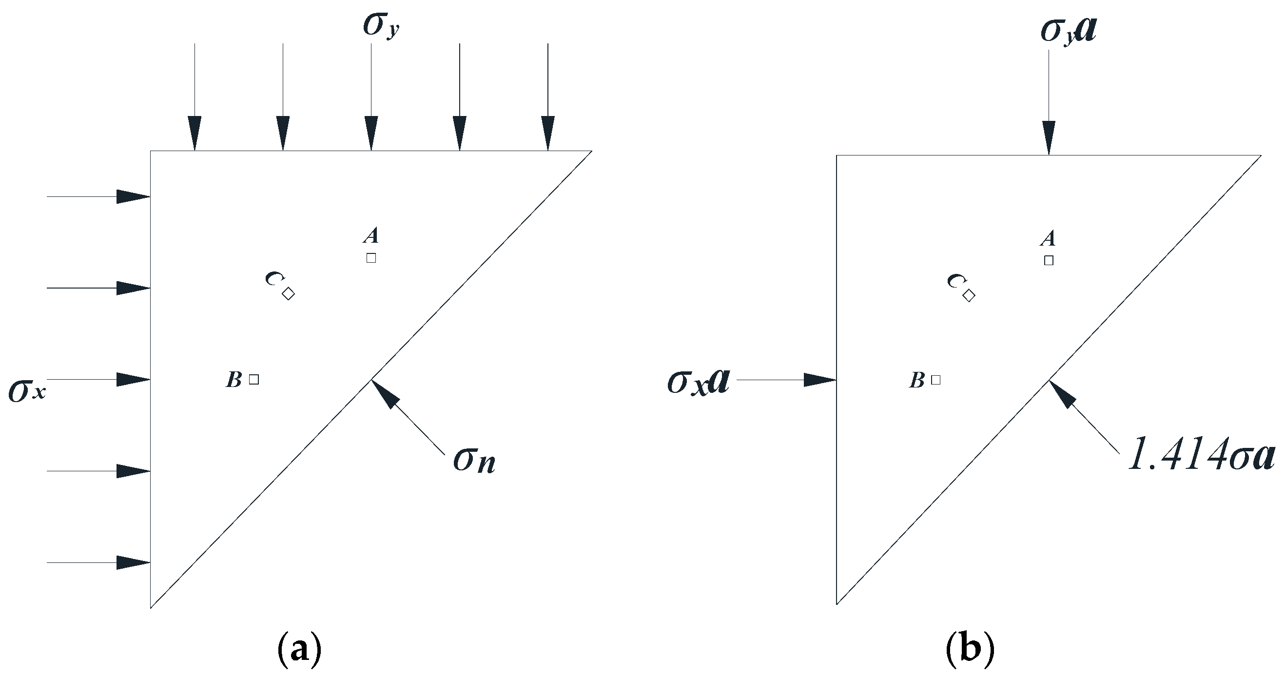
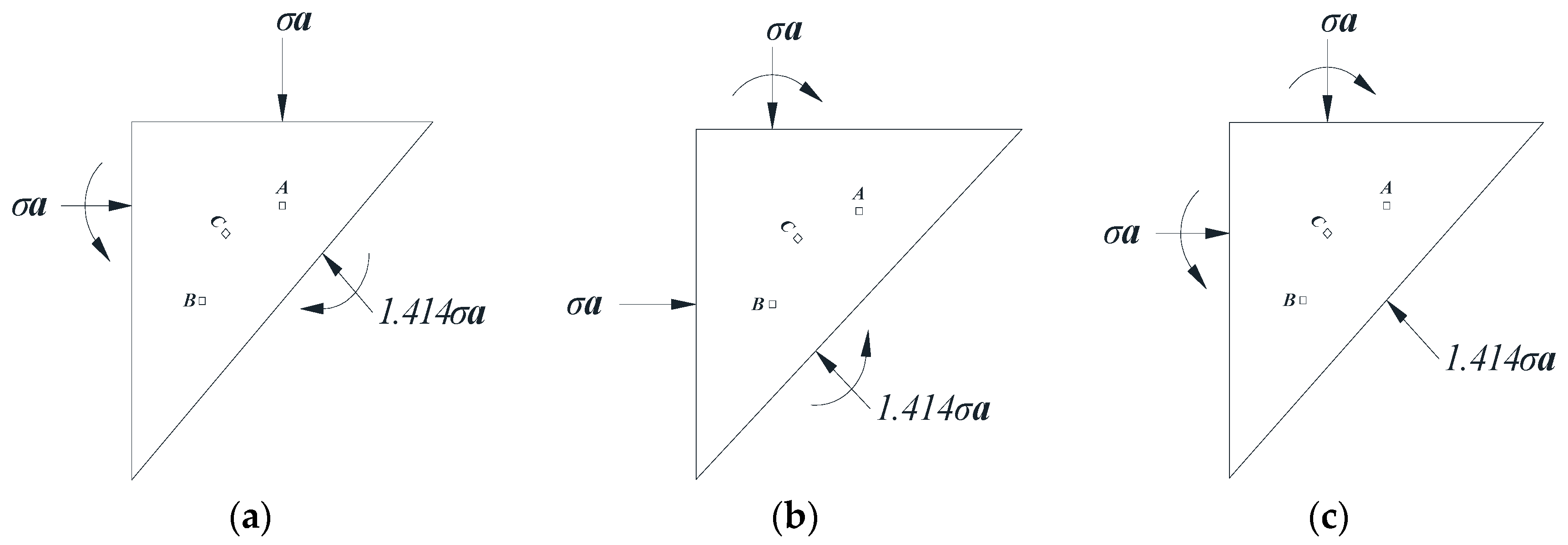
According to the symmetry of force model, half of the model was taken for analysis, as shown in Figure 12a. It was assumed that the side length of model was a, then the model can be simplified, as shown in Figure 12b, based on the relationship between stress and load.
Suppose σ x = σ y = σ , then the concentrated load on each micro element point A, B, and C in the model can be calculated. As shown in Figure 13, σ y a is the concentrated load; M is the additional bending moment generated after the translation of concentrated load, and its magnitude is σ y a d , where d is the translation distance.
It should be noted that the stress applied on the model specimens in this study was far less than the compressive strength of rock. The translational concentrated load inevitably produces an additional bending moment, which means that it produces shear stress in the rock mass, but this is far from sufficient to cause damage to the rock mass. Therefore, the shear effect caused by the additional bending moment on the rock mass is not considered here.
As seen in Figure 13a, the micro element point A is subjected to external loads in both the horizontal and vertical directions, and its magnitude is σ a ; according to Figure 13b, the micro element point B is subjected to external loads in both the horizontal and vertical directions, and its magnitude is σ a ; from Figure 13c, it can be seen that the micro element C is subjected to external loads in both the horizontal and vertical directions, and its magnitude is σ a . In addition, it can be calculated that the magnitude of the external load along the diagonal direction of micro element C is 2 / 2 (about 0.707) σ a . It is assumed that the tensile strength of the micro element increases by 100% in the vertical direction under a vertical concentrated load ( σ a ) compression, and then the tensile strength of the model specimen in this direction becomes 2 σ t .
As the blasting stress wave located in the middle zone (fractured zone) of the blasting is no longer sufficient to crush the rock mass, it is impossible for the stress wave to produce compression failure in the vertical direction of point A. Hence, for point A, only the tensile stress failure in the horizontal direction needs to be discussed. Similarly, it is impossible to produce compression failure in the horizontal direction of point B and perpendicular to the diagonal direction of point C (as shown in the 
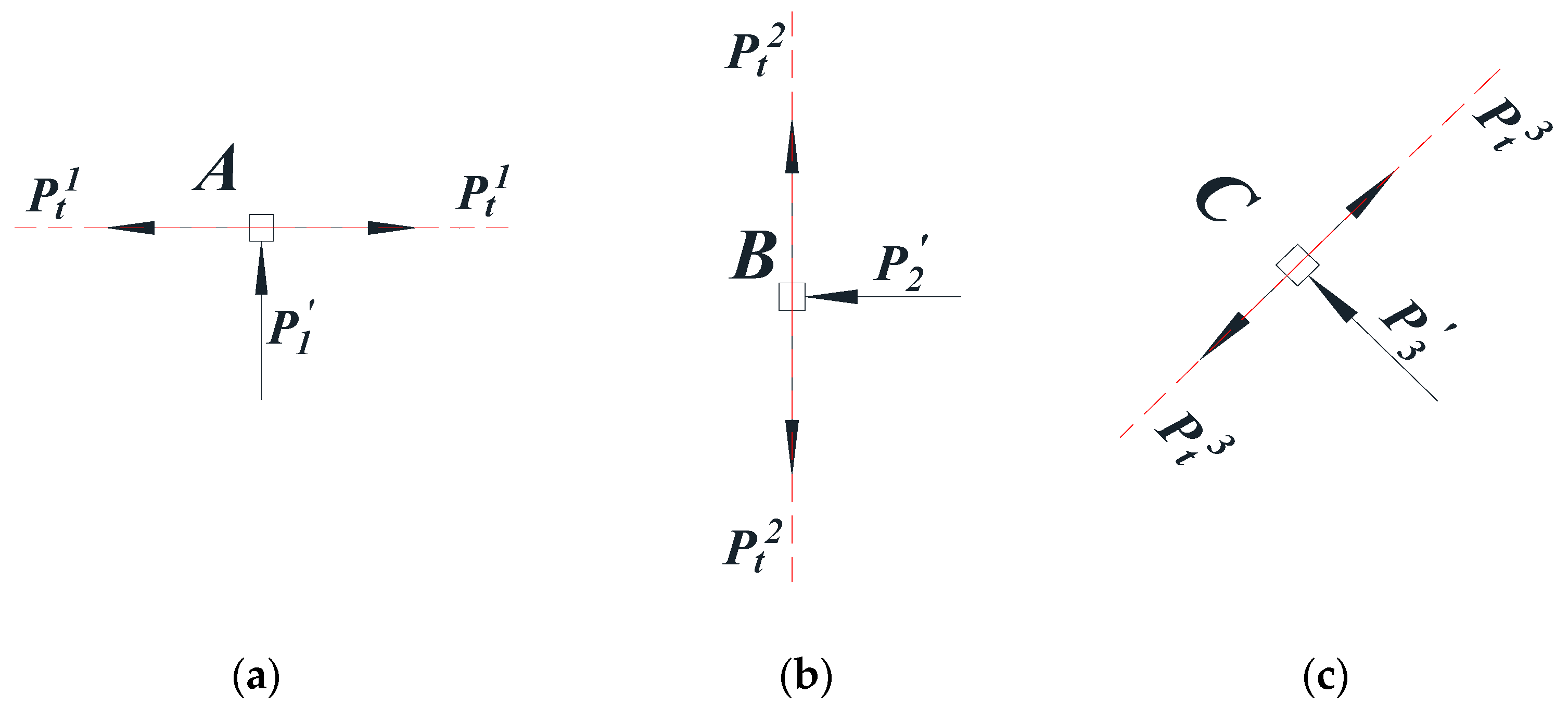
Figure 11b). Therefore, it is only necessary to discuss the failure effect of tensile stresses on these. As seen in Figure 12b, the micro element points A, B, and C affected by the blasting stress wave are taken for stress analysis, as shown in Figure 14.
The above analysis showed that the damage in the middle zone (fractured zone) of blasting is mainly caused by tensile stress. Therefore, for micro element point A, the strength failure criterion is, when P t 1 > 2 σ t , tensile failure of rock mass occurs. Similarly, for micro element points B and C, the tensile strength failure criteria are P t 1 > 2 σ t and   P t 1 > ( 1 + 2 / 2 ) σ t , respectively. It was stated in the hypothesis that all the taken points are from the fractured zone (radial cracks are propagating) and are at the same distance from the blast center. Therefore, with the further attenuation of the stress wave, there must be a situation where 2 σ t > P t ' > ( 1 + 2 / 2 ) σ t , and where P t is attenuated from P t 1 = P t 2 = P t 3 = P t 4 .
It can be concluded that the crack along CC1/DD1 direction will continue to propagate after the propagation has stopped for the crack along AA1/BB1 direction. In other words, the total length of the crack in the direction CC1/DD1 is greater than the total length of the crack in the direction AA1/BB1. Hence, the angle between the propagation direction of the longest radial crack and the direction of principal stress is 45°, which shows that the longest radial crack propagates along the direction at 45° of the macro level.

5. Conclusions

In this study, model specimens made of transparent rock-like materials were used to carry out an experiment of a blasting model under bidirectional equally confining pressure. Based on the analysis of the model test results, a law of blast-induced crack propagation, affected by bi-directional equal confining pressure, was obtained, and the conclusions are summarized as follows:
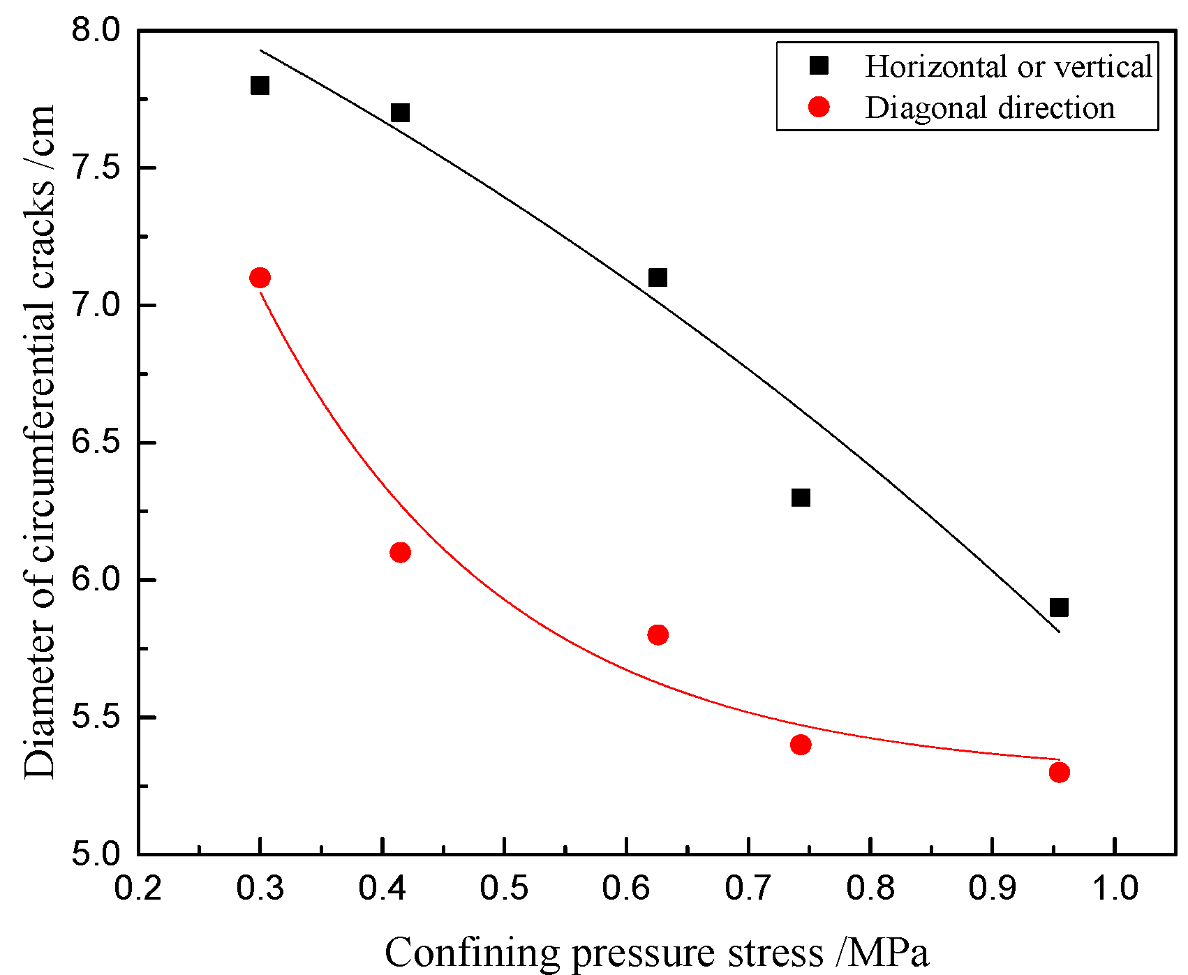
  • The initial stress has the effect of ‘suppression’ of the propagation diameters of the circumferential cracks. With the increase of confining pressure, the average diameters of the circumferential cracks along the horizontal, vertical, and diagonal directions gradually decrease, and the diameters of the circumferential cracks along the diagonal directions are obviously smaller than those along the σ v and σ h directions;
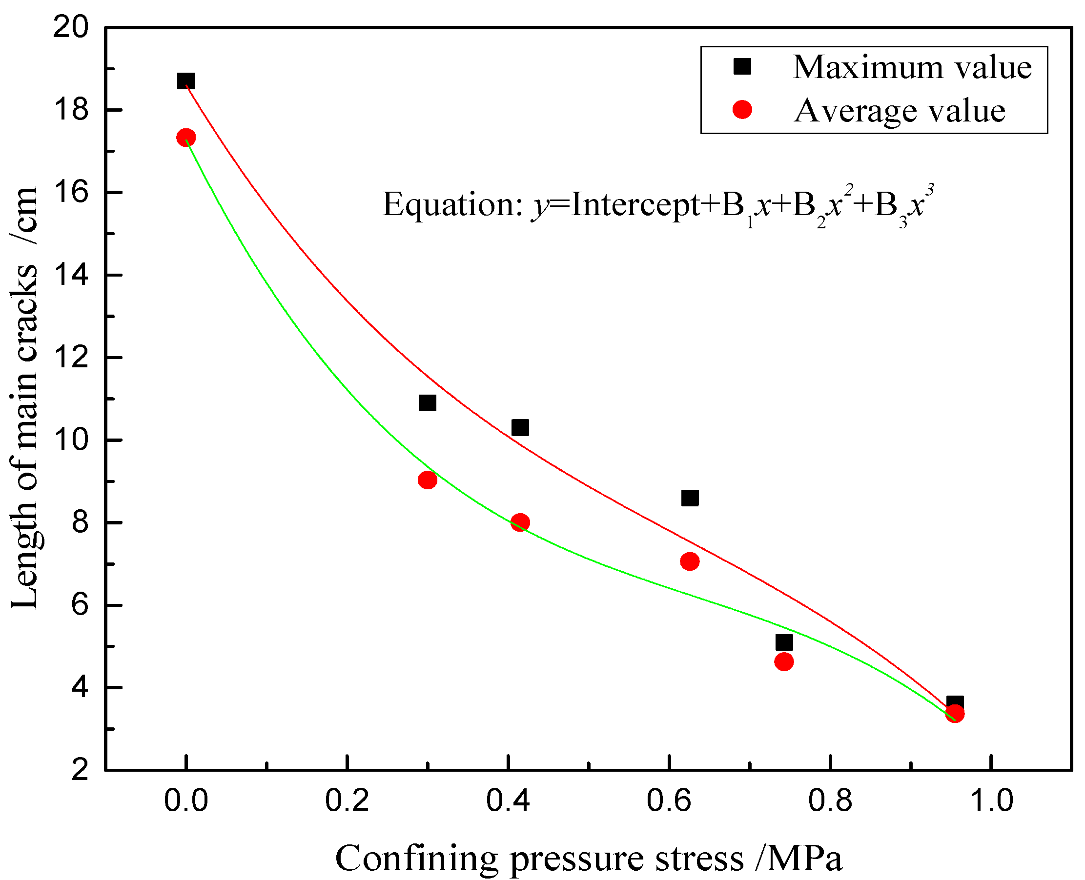
  • The initial stress also has the effect of ‘suppression’ of the number and length of propagated main radial cracks. The greater the load applied on the specimens, the fewer the number of main radial cracks; there is a negative correlation between the propagation length of the main radial cracks and the initial stress. However, with a further increase of confining pressure stress, the propagation lengths of the main radial cracks tend to be the same, and their size is close to the diameter of the circumferential crack;
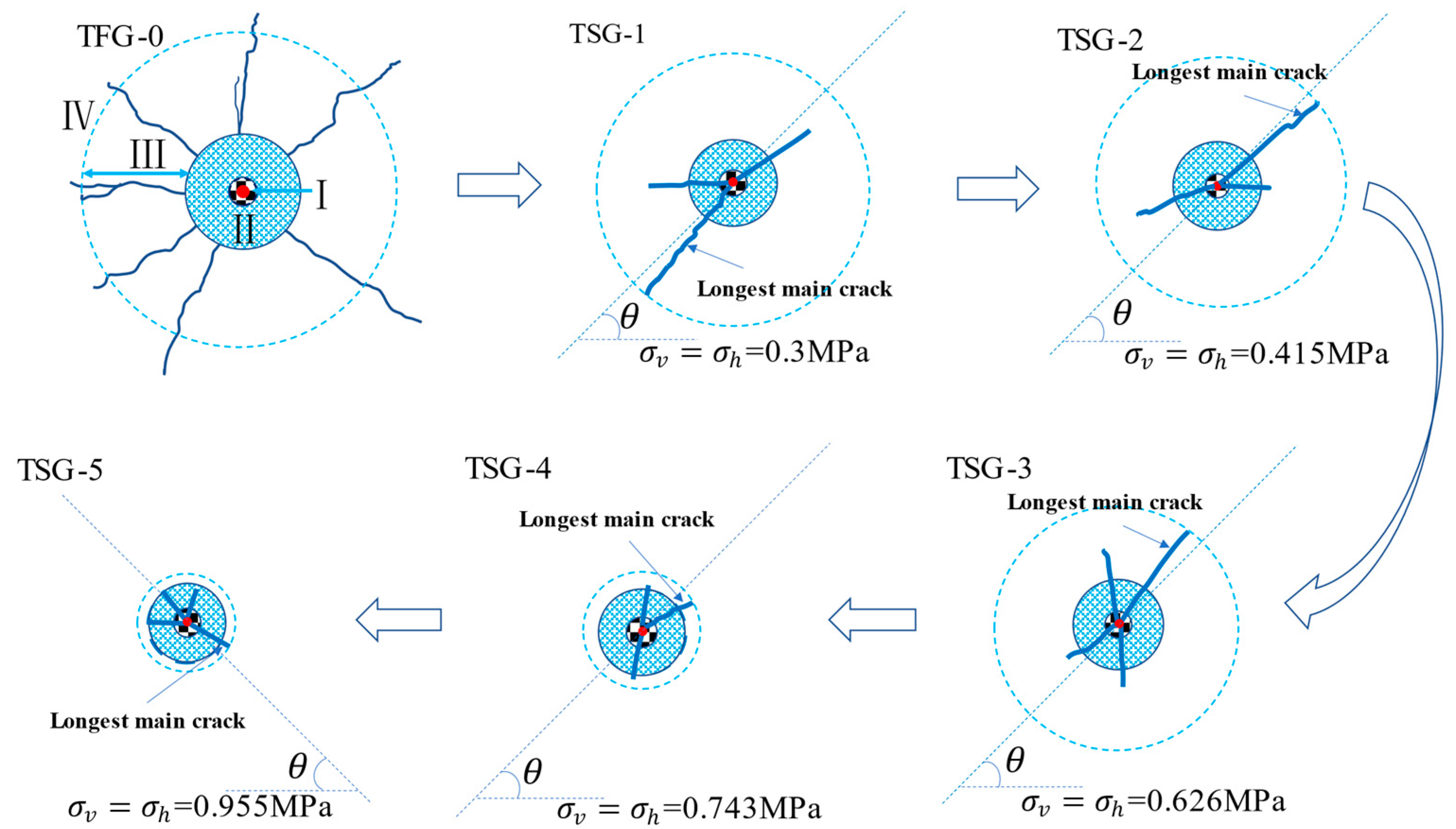
  • The initial stress has a ‘guiding’ effect on the crack propagation direction of the longest main crack. Under the combined dynamic and static loads, the propagation direction of the main radial crack of a model specimen changes from radial without initial stress, to diagonal, and the longest main crack develops along the diagonal; with a further increase of confining pressure, the propagation directions are diversified; that is, the propagation directions are uniformly distributed along the diagonal, σ v and σ h , directions, where the confining stress loses its ‘guiding’ effect on the propagation of the longest main radial cracks.
Obviously, the confining pressure limits the opening of the crack surface, resulting in a greater driving force for crack propagation; that is, more energy is required for crack propagation per unit length. Therefore, under different initial stress conditions, there must be a critical value of energy for crack opening. If it is lower than the critical energy required for crack opening, the crack in the middle zone of blasting is not be able to propagate. Compared with a condition without initial stress (the charging parameters are the same), the ratio of energy used for crack propagation in the middle zone of blasting to the total explosive energy is reduced. According to the principle of energy conservation, it can be concluded that the energy loss in the far zone of blasting, the near zone of blasting, and other areas will inevitably increase. It can be seen that a confining pressure changes the distribution of the blasting energy.
If the energy in the far zone of blasting increases, the stress wave in the far zone of blasting increases; that is, the vibrational intensity increases, which brings great potential safety hazards for deep underground engineering. If the energy in the near zone of blasting increases, the fragmentation degree of the crushed zone is higher, which has no practical significance for blasting excavation. Therefore, it is necessary to study the distribution of blasting energy in a future study and obtain the critical energy value required for crack development under different confining stress conditions, so as to provide a reference for the design of blasting parameters in practical engineering.

Author Contributions

Conceptualization, J.G. and Y.X.; software, J.G.; formal analysis, J.G.; investigation, R.Y. and Z.Z.; writing—original draft preparation, J.G.; writing—review and editing, J.G., Y.X., W.H. and H.W.; visualization, J.G.; supervision, Y.X.; project administration, Y.X.; funding acquisition, J.G. and Y.X. All authors have read and agreed to the published version of the manuscript.

Funding

This research was funded by the university-level key projects of Anhui University of science and technology (No. xjzd2020–16); research grants project for bringing in talents of Anhui University of science and technology; National Natural Science Foundation of China (No. 52104116, No. 52074009).

Data Availability Statement

The datasets generated and analyzed during the current study are available from the corresponding author upon reasonable request.

Conflicts of Interest

The authors declare no conflict of interest.

Nomenclature

α Similarity ratio δ Displacement
LLengthEModulus of elasticity
ν Poisson’s ratio σ Stress
γ Bulk density σ c Compressive strength
σ t Tensile strengthX, Y, ZVolume forces
ε StrainCCohesion
φ Angle of internal frictionTTime

References

  1. Falls, S.D.; Young, R. Acoustic emission and ultrasonic-velocity methods used to characterise the excavation disturbance associated with deep tunnels in hard rock. Tectonophysics 1998, 289, 1–15. [Google Scholar] [CrossRef]
  2. Egger, P. Design and construction aspects of deep tunnels (with particular emphasis on strain softening rocks). Tunn. Undergr. Space Technol. 2000, 15, 403–408. [Google Scholar] [CrossRef]
  3. Dai, J.; Qian, Q.H. Break blasting parameters for driving a roadway in rock with high residual stress. Explos. Shock Waves 2007, 27, 272–277. [Google Scholar]
  4. Xie, L.; Lu, W.; Zhang, Q.; Jiang, Q.; Chen, M.; Zhao, J. Analysis of damage mechanisms and optimization of cut blasting design under high in-situ stresses. Tunn. Undergr. Space Technol. 2017, 66, 19–33. [Google Scholar] [CrossRef]
  5. Xie, L.; Lu, W.; Zhang, Q.; Jiang, Q.; Wang, G.; Zhao, J. Damage evolution mechanisms of rock in deep tunnels induced by cut blasting. Tunn. Undergr. Space Technol. 2016, 58, 257–270. [Google Scholar] [CrossRef]
  6. Xie, L.X.; Lu, W.B.; Jiang, Q.H.; Zhang, Q.B.; Wang, G.H.; Chen, M.; Yan, P. Damage evolution mechanism of deep rock mass during cut blasting. Journal of Central South University. Sci. Technol. 2017, 48, 1252–1260. [Google Scholar]
  7. Lu, W.B.; Chen, M.; Geng, X.; Shu, W.B.; Zhou, C.B. A study of excavation sequence and contour blasting method for under-ground powerhouses of hydropower stations. Tunn. Undergr. Space Technol. 2012, 29, 31–39. [Google Scholar] [CrossRef]
  8. Fan, Y.; Lu, W.B.; Yan, P.; Chen, M.; Zhang, Y.Z. Transient characters of energy changes induced by blasting excavation of deep-buried tunnels. Tunn. Undergr. Space Technol. 2015, 49, 9–17. [Google Scholar] [CrossRef]
  9. Yilmaz, O.; Unlu, T. Three dimensional numerical rock damage analysis under blasting load. Tunn. Undergr. Space Technol. 2013, 38, 266–278. [Google Scholar] [CrossRef]
  10. Sainoki, A.; Emad, M.Z.; Mitri, H.S. Study on the efficiency of destress blasting in deep mine drift development. Can. Geotech. J. 2017, 54, 518–528. [Google Scholar] [CrossRef] [Green Version]
  11. Guo, W.Y.; Zhao, T.B.; Tan, Y.L.; Yu, F.H.; Hu, S.C.; Yang, F.Q. Progressive mitigation method of rock bursts under complicated geological conditions. Int. J. Rock Mech. Min. Sci. 2017, 96, 11–22. [Google Scholar] [CrossRef]
  12. Qiu, J.; Li, D.; Li, X.; Zhu, Q. Numerical investigation on the stress evolution and failure behavior for deep roadway under blasting disturbance. Soil Dyn. Earthq. Eng. 2020, 137, 106278. [Google Scholar] [CrossRef]
  13. Jayasinghe, L.B.; Shang, J.L.; Zhao, Z.Y.; Goh, A.T.C. Numerical investigation into the blasting-induced damage characteristics of rocks considering the role of in-situ stresses and discontinuity persistence. Comput. Geotech. 2019, 116, 103207. [Google Scholar] [CrossRef]
  14. Lak, M.; Marji, M.F.; Bafghi, A.Y.; Abdollahipour, A. A coupled finite difference-boundary element method for modeling the propagation of explosion-induced radial cracks around a wellbore. J. Nat. Gas. Sci. Eng. 2019, 64, 41–51. [Google Scholar] [CrossRef]
  15. Gao, Q.C.; He, J.M.; Feng, G.W.; Zhao, H. Mechanism and technology of controlled blasting for high stress rock tunneling. Blasting 2003, 20, 52–55. [Google Scholar]
  16. Kutter, H.; Fairhurst, C. On the fracture process in blasting. Int. J. Rock Mech. Min. Sci. Geéomeéch. Abstr. 1971, 8, 181–202. [Google Scholar] [CrossRef]
  17. Rossmanith, H.P.; Knasmillner, R.E.; Daehnke, A.; Mishnaevsky, L. Wave propagation, damage evolution, and dynamic fracture extension. Part II. Blasting. Mater. Sci. 1996, 32, 403–410. [Google Scholar] [CrossRef]
  18. Yang, L.Y.; Ma, J.H.; Wang, X.D.; Zhang, W.C.; Zhang, L. Experimental study on blasting crack initiation and propagation behavior in compression stress field. Explos. Shock Waves 2017, 37, 262–268. [Google Scholar]
  19. Zhang, Z.C.; Xiao, Z.X.; Hu, J.; Li, C.X.; Zhang, Y.J. Experimental study on the wave transmission effect of the initial stress field as transmitting of quake wave from rock blasting. Ind. Miner. Process. 2005, 34, 21–24. [Google Scholar]
  20. Xiao, Z.X.; Zhang, Z.C.; Li, D.M. The influence of initial stress field on blasting. J. Chin. Coal Soc. 1996, 21, 497–501. [Google Scholar]
  21. Liu, Q.S.; Liu, K.D. Characteristics of in-situ stress field for deep levels in Huainan coal mine. Rock Soil Mech. 2012, 33, 2089–2096. [Google Scholar]
  22. Wan, Y.L.; Wang, S.R. Experiment study on damage model of rock fragmentation by blasting. Eng. Blasting 1997, 3, 29–33. [Google Scholar]
  23. Ge, J.; Xu, Y. A Method for Making Transparent Hard Rock-Like Material and Its Application. Adv. Mater. Sci. Eng. 2019, 2019, 1274171. [Google Scholar] [CrossRef] [Green Version]
  24. Zhang, Q.Y.; Chen, X.G.; Lin, B.; Liu, D.J.; Zhang, N. Study of 3D geomechanical model test of zonal disintegration of sur-rounding rock of deep tunnel. Chin. J. Rock Mech. Eng. 2009, 28, 1757–1766. [Google Scholar]
  25. Xu, Y.; Ge, J.; Huang, W. Energy Analysis on Dynamic Fragmentation Degree of Cemented Sand Specimens under Confining Pressure. Shock. Vib. 2019, 2019, 5893957. [Google Scholar] [CrossRef]
  26. Xu, Y.; Meng, Y.P.; Cheng, Y.S. Study on control of blast crack by decoupling charge index. Chin. J. Rock Mech. Eng. 2002, 21, 1843–1847. [Google Scholar]
  27. Yuan, W.H.; Ma, Q.Y.; Huang, W. Model experiment and analysis of wedge-shaped cutting millisecond blasting. Chin. J. Rock Mech. Eng. 2012, 31, 3352–3356. [Google Scholar]
  28. Chi, L.Y.; Zhang, Z.X.; Arne, A.; Charlie, C.L. Experimental Investigation of Blast-Induced Fractures in Rock Cylinders. Rock Mech. Rock Eng. 2019, 52, 2569–2584. [Google Scholar] [CrossRef]
  29. Hajibagherpour, A.; Mansouri, H.; Bahaaddini, M. Numerical modeling of the fractured zones around a blasthole. Comput. Geotech. 2020, 123, 103535. [Google Scholar] [CrossRef]
  30. Lak, M.; Marji, M.F.; Bafghi, A.Y.; Abdollahipour, A. Analytical and numerical modeling of rock blasting operations using a two-dimensional elasto-dynamic Green’s function. Int. J. Rock Mech. Min. Sci. 2019, 114, 208–217. [Google Scholar] [CrossRef]
  31. Mohammadi, S.S.; Amnieh, H.B.; Bahadori, M. Predicting ground vibration caused by blasting operations in sarcheshmeh copper mine considering the charge type by adaptive neuro-fuzzy inference system (ANFIS). Arch. Min. Sci. 2011, 56, 701–710. [Google Scholar]
  32. Yi, C.P.; Daniel, J.; Jenny, G. Effects of in-situ stresses on the fracturing of rock by blasting. Comput. Geotech. 2018, 104, 321–330. [Google Scholar] [CrossRef]
  33. Tao, J.; Yang, X.-G.; Li, H.-T.; Zhou, J.-W.; Fan, G.; Lu, G.-D. Effects of in-situ stresses on dynamic rock responses under blast loading. Mech. Mater. 2020, 145, 103374. [Google Scholar] [CrossRef]
  34. Qin, X.H.; Zhang, P.; Feng, C.J.; Sun, W.F.; Tan, C.X.; Chen, Q.C.; Peng, Y.R. In-Situ Stress Measurements and Slip Stability of Major Faults in Beijing Region. Chin. J. Geophys. 2014, 57, 415–430. [Google Scholar]
  35. Brown, E.; Hoek, E. Trends in relationships between measured in-situ stresses and depth. Int. J. Rock Mech. Min. Sci. Geéomeéch. Abstr. 1978, 15, 211–215. [Google Scholar] [CrossRef]
  36. Hu, Y.G.; Lu, W.B.; Chen, M.; Yan, P.; Yang, J.H. Comparison of Blast-Induced Damage Between Presplit and Smooth Blasting of High Rock Slope. Rock Mech. Rock Eng. 2014, 47, 1307–1320. [Google Scholar] [CrossRef]
  37. Qin, Q.H. Some advances in rock blasting dynamics. Chin. J. Rock Mech. Eng. 2009, 28, 1945–1968. [Google Scholar]
Figure 1. Device for plane stress loading of a model specimen.
Sustainability 13 12093 g001
Figure 2. Schematic diagram of the charging structure.
Sustainability 13 12093 g002
Figure 3. Transparent model specimens after explosion: (a) TSG-0 (b) TSG-1 (c) TSG-2 (d) TSG-3 (e) TSG-4 (f) TSG-5.
Sustainability 13 12093 g003
Figure 4. Internal action of blasting. R0—charging radius, R1—radius of crushed zone, and R2—radius of fractured zone.
Sustainability 13 12093 g004
Figure 5. Crack distribution in transparent model specimens.
Sustainability 13 12093 g005
Figure 6. The variation of crack propagation with different stress loads in model specimens.
Sustainability 13 12093 g006
Figure 7. Relationship between the average diameter of the circumferential cracks and confining stress.
Sustainability 13 12093 g007
Figure 8. Variation of main crack length with loading stress.
Sustainability 13 12093 g008
Figure 9. Force model of deep rock mass under blasting.
Sustainability 13 12093 g009
Figure 10. Force model of rock under bidirectional equal confining pressure and explosive load: (a) at the time of explosive detonating; (b) at the time of stress wave propagating to fractured zone.
Sustainability 13 12093 g010
Figure 11. Equivalent force model of rock blasting under a bidirectional initial stress: (a) external loading model; (b) internal loading model.
Sustainability 13 12093 g011
Figure 12. Force analysis of rock mass under an initial static load: (a) half of the model in Figure 11a; (b) the model simplified from Figure 12(a).
Sustainability 13 12093 g012
Figure 13. Force analysis of a micro element point in a rock mass under an initial static load: (a) force analysis on point A; (b) force analysis on point B; (c) force analysis on point C.
Sustainability 13 12093 g013
Figure 14. Force analysis of micro element points in rock mass under a dynamic blasting load: (a) force analysis on point A; (b) force analysis on point B; (c) force analysis on point C.
Sustainability 13 12093 g014
Table 1. Physicomechanical parameters of the prototype rock.
Material Type γ KN · m 3 E GPa C MPa φ ( ° ) ν σ c MPa σ t MPa
Sandstone2712.9710.00430.2713521.5
γ —Bulk density, E —Deformation modulus, C —Cohesion, φ —Internal friction angle/(°), ν —Poisson’s ratio, σ c —Compressive strength, σ t —Tensile strength.
Table 2. Basic mechanical parameters of the transparent rock-like material.
Physical Quantities ρ C E/MPa ν σ c / MPa σ t / MPa
Numerical value12302423360 ~ 18020.26 ~ 0.313.29 ~ 960.26 ~ 7.22
ρ —Density/ kg · m 3 , C —Compressional wave velocity/(m/s).
Table 3. Explosive physical parameters of the special small detonator.
Geometric   Dimension / × 10 3   m Main IngredientsExplosive Charge/gDensity
/ k g · m 3
Detonation Velocity/m/s
Length Diameter
30 3DDNP0.0437005400
DDNP-dinitrodiazophenol, molecular formula - C 6 H 2 N 4 O 5 .
Table 4. Basic physical and mechanical parameters of the model specimens.
NumberMass Ratio γ K N · m 3 E MPa ν σ c MPa σ t MPa
TSG-0∼510:10:112.35520.287.50.586
The mass ratio of 10:10:1 was, namely, epoxy resin: curing agent: saturated rosin solution.
Table 5. Test scheme for blasting of transparent model specimens.
Specimen NumberBuried Depth/m σ v   =   σ h
CP Design /MPaCP Loading/MPa
TSG-0000
TSG-14100.31.2
TSG-25600.421.7
TSG-38500.632.6
TSG-410000.743.1
TSG-513000.964.0
CP—confining pressure.
Table 6. The diameters of the circumferential cracks in the model specimens.
NumberDiameter/cm
Along   σ v Along   σ h Mean VSalueAlong Diagonal-1Along Diagonal-2Mean Value
TSG-17.48.27.87.27.07.1
TSG-27.67.87.76.06.26.1
TSG-37.07.27.15.85.85.8
TSG-46.26.46.35.55.35.4
TSG-56.05.85.95.35.35.3
Table 7. The length of the radial main cracks in the model specimens.
NumberLength of Radial Main Cracks/cmMean Value/cm
1#2#3#
TSG-018.716.816.517.33
TSG-18.210.989.03
TSG-210.38.84.98.0
TSG-36.88.65.87.06
TSG-45.14.44.44.63
TSG-53.63.43.13.37
Cracks 1#∼3# are the top three in length of the main radial cracks in the model specimens.
Publisher’s Note: MDPI stays neutral with regard to jurisdictional claims in published maps and institutional affiliations.

