Article

Temperature Field Calculation of the Hybrid Heat Pipe Cooled Permanent Magnet Synchronous Motor for Electric Vehicles Based on Equivalent Thermal Network Method

1
School of Electrical Engineering, Tiangong University, Tianjin 300387, China
2
Advanced Electrical Equipment Innovation Center, Zhejiang University, Hangzhou 311107, China
*
Author to whom correspondence should be addressed.
World Electr. Veh. J. 2023, 14(6), 141; https://doi.org/10.3390/wevj14060141
Submission received: 28 April 2023 / Revised: 18 May 2023 / Accepted: 23 May 2023 / Published: 27 May 2023

Abstract

:
A hybrid heat-pipe cooling structure for the permanent magnet synchronous motor for electric vehicles was analyzed in this paper to effectively equalize the axial temperature rise and reduce the average temperature of each heat-generating component in the motor. A temperature field calculation method for the hybrid heat-pipe cooling permanent magnet synchronous motor based on an equivalent thermal network method was proposed in this paper to save computing resources in temperature field analyses for hybrid heat-pipe cooling motors. The results were verified against the simulation results of the computational fluid dynamics method under three common operating conditions for electric vehicles. The error was proven to be within 5%. The calculation time of the proposed method was compared with the computational fluid dynamics method, which demonstrated that the calculation time of the proposed method was within 194 s.

1. Introduction

With the development of electric vehicle technology, its advantages, such as low energy consumption and no harmful emissions. have gradually made it a major transportation alternative to traditional internal combustion engine vehicles, providing an effective solution to the problem of human carbon neutrality [1]. Currently, common electric vehicle drive motors include asynchronous motors and permanent magnet synchronous motors (PMSM). With their high torque density and high efficiency, the PMSM has become the main traction motor used in electric vehicles such as the Tesla Model 3 and Porsche Taycan [2]. With the gradual maturity of electric vehicle technology, the permanent magnet synchronous motor as a drive motor is also developing in the direction of higher torque density and higher efficiency, which leads to a sharp increase in the temperature rise of the internal heating components of the motor, and the design of a reasonable cooling structure for it has become a hot research topic today.
In order to realize a rational design of the motor cooling system, an accurate calculation technique of the motor temperature field is an important tool in motor design work. Common temperature field calculation methods for permanent magnet synchronous motors mainly use commercial finite volume method temperature field calculation procedures based on computational fluid dynamics (CFD) [3], a main problem of which is that the calculation of complex motor cooling structures is time-consuming and requires a lot of computational resources. Such problems are particularly evident in the calculation of the motor temperature field of phase-change cooling structures [4], and it has become particularly important to improve the efficiency of the calculation of the motor temperature field of phase-change cooling with the development of phase-change materials and high-performance thermal conductivity materials such as heat pipes.
The equivalent thermal network method is a highly efficient method to calculate the temperature field of a motor, which is based on the principle of calculating the thermal resistance in the internal heat-transfer path of the motor to generate a thermal resistance network [5,6]. It uses a nodal voltage method similar to the circuit, with the losses generated by the internal heat-generating parts of the motor as the input quantity and the external ambient temperature as the reference node; the temperature rise of each heat-generating part of the motor is finally calculated after several iterations. J. Nerg et al. focused on a T-shaped equivalent thermal resistance network [7]. The advantages and disadvantages of the conventional thermal resistance network and the T-shaped equivalent thermal network were compared in the paper. The equivalent thermal network model of a surface-mounted permanent magnet synchronous motor was built by Si J et al. [8]. The improved thermal network model can derive the motor’s temperature field distribution faster without complete motor parameters [9,10,11]. Only axial and radial heat transfer is generally concerned in the temperature field analysis of permanent magnet synchronous motors for electric vehicles [12]. Dawei Liang et al. proposed a two-dimensional thermal resistance network model that considers both axial and radial heat transfer and analyzed its effectiveness in improving the efficiency of motor temperature field calculation with guaranteed accuracy [13]. The temperature field of a permanent magnet synchronous motor for an unmanned aircraft was analyzed by Zhang C et al. The fixed heat pipe cools the motor on winding. The temperature field of the heat-pipe cooled motor was calculated based on the equivalent thermal network method [14]. Liu L et al. analyzed and calculated the temperature field of a permanent magnet synchronous motor for electric vehicles with fixed heat-pipe cooling using the equivalent thermal network method. The paper considered three common operating conditions of electric vehicles and compared the calculation results with CFD simulation results [15]. Sun D et al. analyzed the phase-change process inside the heat pipe in a heat-pipe cooling structure using the commercial CFD software Fluent [16], which analyzed the phase-change process of the fluid inside the heat pipe and the fluid motion state. Shi X et al. analyzed the state of the working mass inside the heat pipe in a rotating heat-pipe cooling structure for a high-speed machine tool motor using Fluent [17]. Subsequently, the correctness of their simulation analysis was proved using equivalent experiments by their research team [18].
According to the current research status, scholars mainly focus on calculating the temperature field of heat-pipe cooled motors for electric vehicles with fixed or rotating heat-pipe cooling structures. There is less research on analyzing the temperature field of motors with hybrid heat-pipe cooling structures based on the equivalent heat network method. The hybrid heat-pipe cooling structures include annular fixed and rotating heat pipes, and the equivalent thermal conductivity of rotating heat pipes varies with the motor speed, which leads to errors in the results obtained from the analytical calculation of the equivalent thermal network. The phase-change process of the internal mass during the operation of the rotating heat pipe cannot be analyzed by the equivalent thermal network method [19]. In this paper, a method to calculate the temperature field of the hybrid heat-pipe cooled motor based on the equivalent heat network method was proposed. The temperature field calculation and analysis were carried out for a hybrid heat-pipe cooled permanent magnet synchronous motor for electric vehicles using both fixed and rotating heat-pipe cooling. In this paper, the equivalent thermal conductivity of the fixed heat pipe and the rotating heat pipe under different operating conditions of the electric vehicle were obtained through the designed equivalent experiments, and the accuracy of the CFD calculation results was verified. The validity of the proposed temperature field calculation model was verified by comparing the model with the CFD simulation results. Finally, the computational time consumed by the proposed equivalent thermal network method of motor temperature field calculation was compared to the conventional CFD method in this paper.

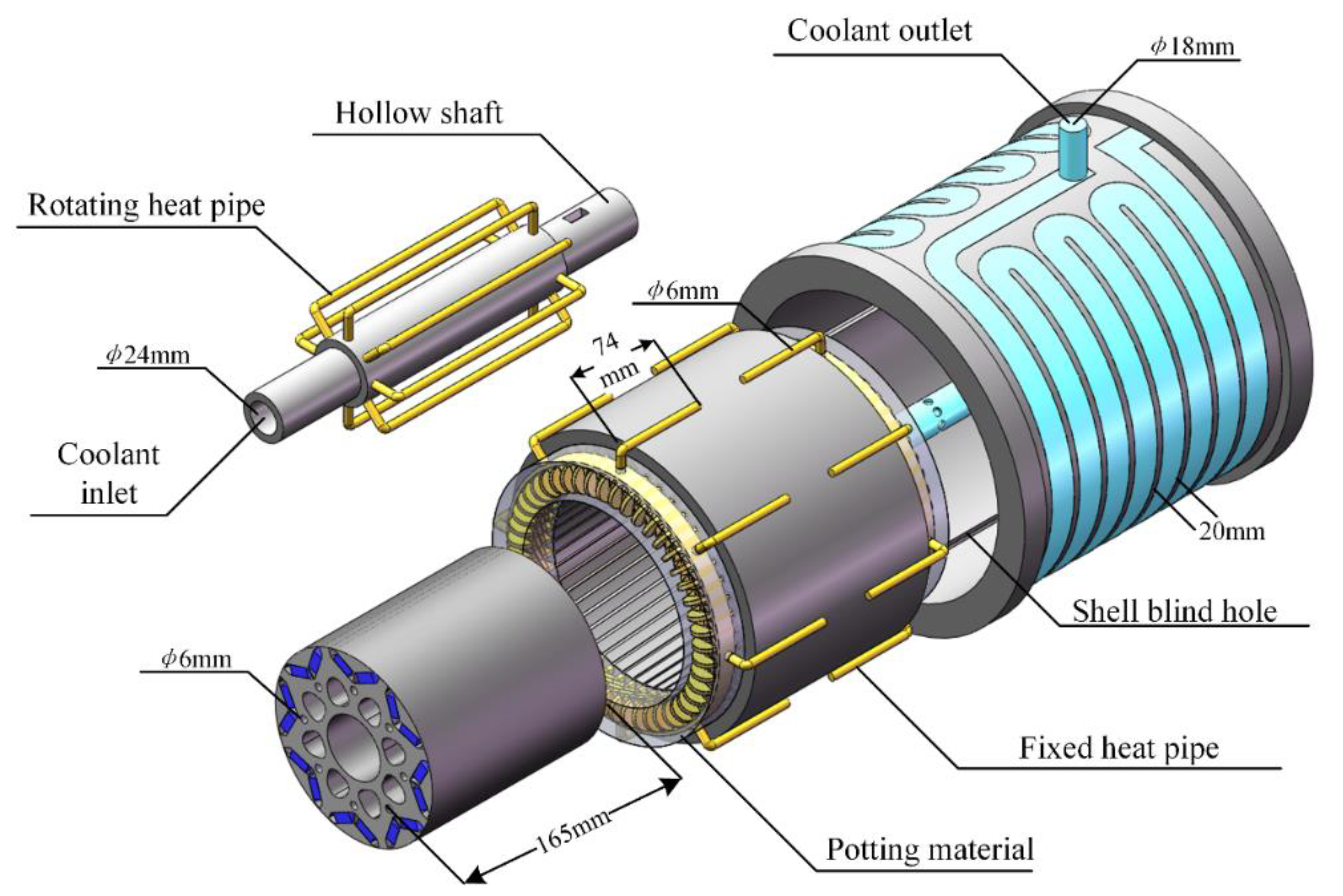
2. Hybrid Heat-Pipe Cooling PMSM for EVs

2.1. Motor Model

The hybrid heat-pipe cooling structure adopted in the PMSM for EVs. The main features of the three-dimensional structure are shown in Figure 1.
It can be seen that there are two forms of heat pipes in the hybrid heat-pipe cooling structure, one is rotating and the other is fixed. An additional heat path from the rotor and permanent magnet to the water-cooled hollow shaft of the motor was built using the U-shaped rotating heat pipe installed inside the rotor, so that the large amount of heat generated by the rotor and permanent magnet when the motor is in high-speed operating conditions can be rapidly transferred to the cooling water inside the hollow shaft. The problem of the high average temperature rise of the rotor and permanent magnet, and uneven axial temperature rise, was solved effectively [20]. The additional heat path from the end winding to the motor water-cooled shell was constructed by using the ring-shaped fixed heat pipe, so that a large amount of heat generated by the winding can be quickly transferred to the motor-cooling water. The problem of the high temperature rise at the end of the winding was solved [21]. To further enhance the heat-transfer efficiency from the motor winding to the annular fixed heat pipe, a high thermal conductivity potting material was used to pot the winding end to the annular fixed heat pipe.

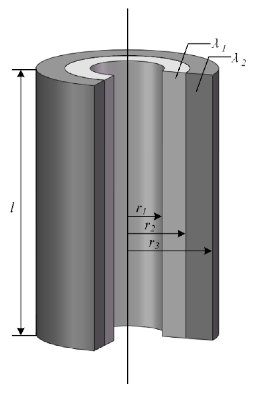
2.2. The Equivalent Thermal Conductivity of Hybrid Heat Pipe

The parameters of the hybrid heat-pipe cooling PMSM researched in this paper are shown in Table 1. In order to obtain the different thermal conductivity of the hybrid heat pipe under different working conditions of the hybrid heat-pipe cooling PMSM, the thermal conductivity and the internal mass motion state of the fixed and rotating heat pipe under different operating conditions of the PMSM were simulated by the CFD method. The VOF two-phase flow model and the LEE phase-change model were used to simulate the phase-change process and the internal mass motion of the rotating heat pipe at different speeds of the motor. The main working medium used in the working process of the rotating heat pipe involved in this paper was distilled water, the gaseous working medium was water vapor, and the phase-transition temperature of the liquid working medium inside the heat pipe was 15 °C.
The volume fraction of the internal mass of the rotating heat pipe under rated working condition is shown in Figure 2. It can be seen that the liquid mass is mainly distributed in the radial top of the rotating heat pipe under the centrifugal force of rotor rotation.
The temperature distribution cloud diagram of the rotating heat pipe at the rated working condition of the motor is shown in Figure 3. As shown in the diagram, the evaporation section of the heat pipe absorbs a large amount of heat generated by the rotor and permanent magnet, and the condensation section of the heat pipe effectively transfers the heat to the cooling water inside the hollow shaft of the motor.
The equivalent thermal conductivity of the heat pipe calculated by the CFD method is shown in Table 2. It can be seen that when the PMSM for EVs is in the maximum torque working condition, that is, the speed is 600 r/min and the output torque is 380 N·m, the calculated thermal-resistance value is low. When the motor is at rated speed, due to the high motor speed, the fluid mass inside the rotating heat pipe is further accelerated back to the evaporation section by the centrifugal force of the rotor rotation, which further increases the equivalent thermal conductivity.

3. Thermal Network Analysis of Hybrid Heat-Pipe Cooling Motor

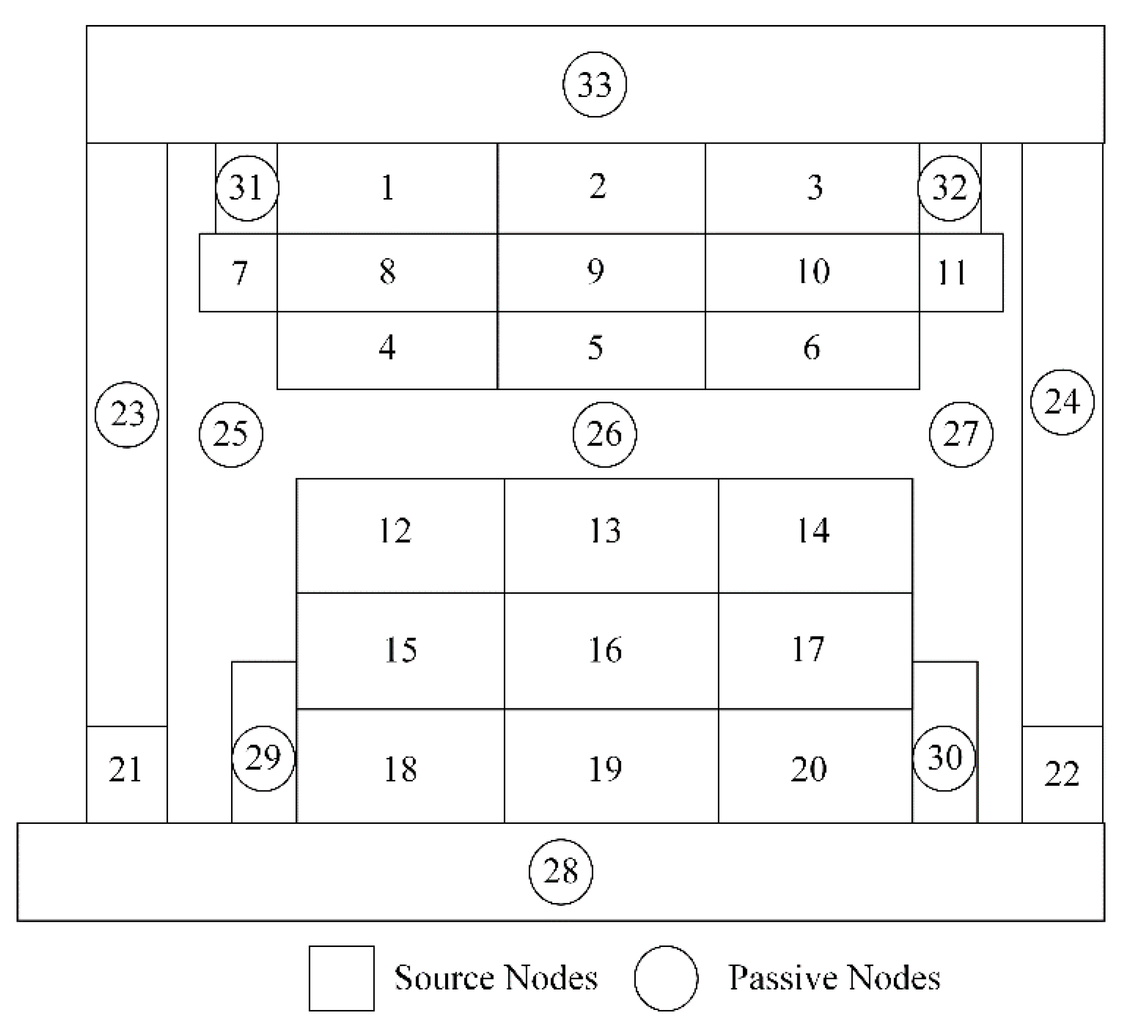
3.1. Thermal Network Model Construction

The specific process of calculating the temperature field of the hybrid heat-pipe cooling motor by using the equivalent thermal network method is shown in Figure 4. Before the thermal network construction of the motor, the components with little influence on the temperature field calculation in the motor, such as the junction box, are generally simplified. After simplifying the motor model, the equivalent thermal network was established by treating the heating parts in the motor as nodes and the heat-transfer path as thermal resistance, and the thermal resistance of each heat-transfer path in the motor was calculated according to different working conditions and different speeds of the motor. The thermal resistance mainly included contact and convective thermal resistance between different materials. Then, the core loss of the stator and rotor, the eddy current loss of the permanent magnet, the copper loss of the winding, and the mechanical friction loss under three typical working conditions of the motor were calculated using FEA software and an empirical formula. These losses were taken as input values into the established equivalent thermal network. The node voltage method in the analogy circuit used the temperature of the external coolant as the reference node to obtain the cooling matrix. Finally, the cooling matrix was calculated and iteratively corrected until the temperature of each node, satisfying the residual conditions, was obtained.
Firstly, the hybrid heat-pipe cooling motor is divided into thermal network nodes according to the materials of each heating component, and different nodes are connected by thermal resistance according to heat conduction and heat convection. In order to improve the calculation efficiency, the following assumptions are proposed under the premise of ensuring calculation accuracy [22,23]:
  • The motor’s cooling effect and temperature distribution are circumferentially symmetrical.;
  • All the heat generated in the motor is regarded as all derived from the coolant, and the coolant temperature is regarded as the external node;
  • Due to the heat pipe’s relatively large thermal conductivity, heat pipe’s additional heat path is regarded as heat conduction only through the heat pipe.
  • All the losses of the rotor and the permanent magnet are transmitted from the heat pipe to the coolant in the hollow shaft.
Based on the above settings, the motor can be divided into stator yoke, stator teeth, winding, end winding heat pipe, thermal conductive potting material, rotor boot, permanent magnet, rotor yoke, rotor heat pipe, hollow shaft, bearing, end cover and shell according to the material and structure. Considering that the thermal conductivity of stator core and rotor core is low due to the stacking of silicon steel sheets in the axial direction, the stator core, rotor core, and permanent magnet are divided into three parts along the axial direction. Finally, the hybrid heat-pipe cooling motor is simplified to the equivalent node distribution diagram shown in Figure 5.
According to the equivalent node diagram of the motor, the thermal resistance of heat conduction or thermal convection type can be added between the nodes, and the equivalent thermal network of the hybrid heat-pipe cooling permanent magnet synchronous motor for electric vehicle can be obtained. Among them, nodes 1–3 are stator yokes, nodes 7–11 are windings, nodes 4–6 are stator teeth, nodes 12–14 are rotor boots, nodes 18–20 are rotor yokes, nodes 15–17 are permanent magnets, nodes 21–22 are bearings, nodes 28 are hollow shafts, nodes 29–30 are rotor rotating heat pipes, nodes 25–27 are air domains, and nodes 23–24 are motor end covers. Node 31–32 is the heat pipe at the end winding, and node 33 is the water-cooled shell.

3.2. Thermal Resistance Calculation of Hybrid Heat-Pipe Cooling Structure

The heat transfer modes involved in the internal heating components of permanent magnet synchronous motor for electric vehicles include heat conduction, convective heat transfer and radiation heat transfer. This paper mainly analyzes the heat conduction and convective heat transfer inside the motor.
The form of heat conduction of permanent magnet synchronous motor for electric vehicles is mainly divided into plate heat conduction and cylinder heat conduction [24]. Most of the heat conduction in the motor is cylindrical heat conduction. The schematic diagram of the heat conduction principle on the cylinder wall is shown in Figure 6. For example, the stator yoke, the rotor yoke, the annular heat pipe and the rotating heat pipe can be equivalent to the heat conduction of the cylinder wall. The thermal resistance calculation method is as follows:
R = 1 2 π l λ 1 ln r 2 r 1 + 1 2 π l λ 2 ln r 3 r 2
where, l is the equivalent length of the cylinder parts such as the stator and rotor and the annular heat pipe, λ1 is the thermal conductivity of the contact part 1, λ2 is the thermal conductivity of the contact part 2, r1 is the inner meridian of the cylinder, r2 is the interface radius of the two-cylinder parts, and r3 is the outer diameter of the cylinder.
The air and cooling water in the motor belong to the fluid, and the fluid is mainly divided into laminar flow and turbulent flow according to its flow state [25,26]. In the motor, the critical Reynolds number is mainly used to judge the flow state of the fluid. It is generally believed that the fluid is laminar when the Reynolds number is less than 2200, and the fluid is turbulent when the Reynolds number is greater than 2200. The air in the air gap of the motor studied in this paper is in a turbulent state under the rated and maximum speed conditions, and the fluid in the air gap is in a laminar state under the maximum torque condition. As shown in Formula (7), the equivalent Reynolds number of the fluid in the motor can be calculated:
R e = u D ν
where, D is the equivalent diameter of the cylinder, v is the kinematic viscosity coefficient of the fluid, and u is the velocity of the fluid.
According to the calculated equivalent Reynolds number, the Nusselt number of the fluid can be further calculated, and the convective heat transfer coefficient between the fluid and the solid can be finally obtained [27].
N u = { 1.86 R e 1 / 3 Pr 1 / 3 ( D l ) 1 / 3 ( u v ) 0.14 R e < 2200 0.023 R e 0.8 Pr 0.4 R e > 2200
α = N u λ D
where, λ is the thermal conductivity of the fluid, Nu is the Nusselt number of the fluid, Re is the Reynolds number of the fluid, Pr is the Prandtl constant, D is the equivalent diameter of the cylinder, L is the equivalent length of the cylinder, α is the convective heat transfer coefficient.
According to the convection heat transfer coefficient of the fluid at different solid boundaries calculated above, the corresponding thermal convection thermal resistance can be obtained by substituting it into the following formula.
R = 1 S α
where, S is the heat transfer area of the fluid-solid boundary.
The cooling structure of the hybrid heat pipe mainly includes the contact thermal resistance from the end winding to the annular fixed heat pipe, the convective thermal resistance from the rotor yoke to the cooling water in the hollow shaft through the U-shaped rotating heat pipe, and the equivalent thermal resistance of the annular heat pipe and the U-shaped rotating heat pipe itself. The three types of thermal resistance in the hybrid heat-pipe cooling structure are calculated below:
  • The thermal resistance from the end winding to the annular fixed heat pipe is R87 and R1011. Taking R87 as an example:
    R 87 = d cudb 2 λ cu S 87 + 1 λ hp S 87
    where, dcudb is the radial thickness of the end winding, and λhp is the static thermal conductivity of the heat pipe.
  • The thermal resistance of the rotor yoke through the rotating heat pipe to the cooling water inside the hollow shaft includes R1828, R1928 and R2028. The thermal resistance R1828 is analyzed as an example:
    R 1828 = 1 2 π λ stj l / 3 ln r re r m + 1 α q S 1828
    where, αq is the convective heat transfer coefficient between the heat pipe and the cooling water, and S1828 is the equivalent heat transfer area between the rotating heat pipe and the cooling water.
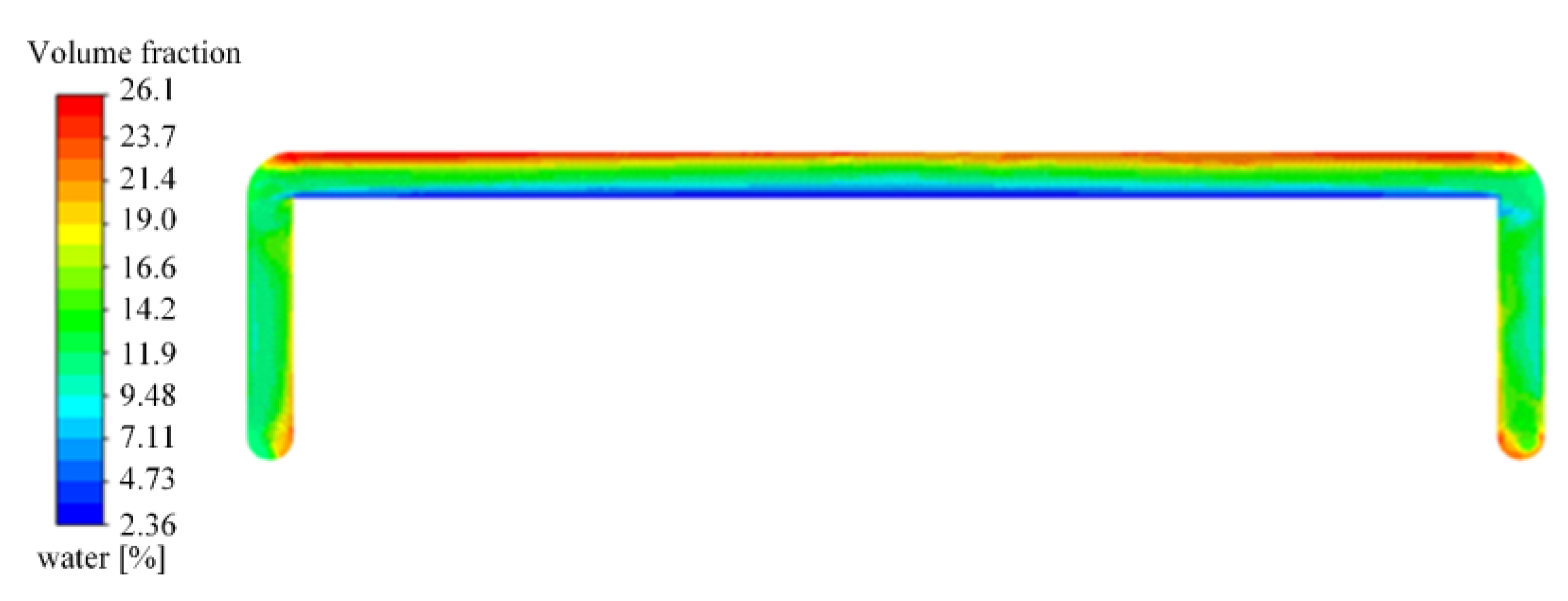
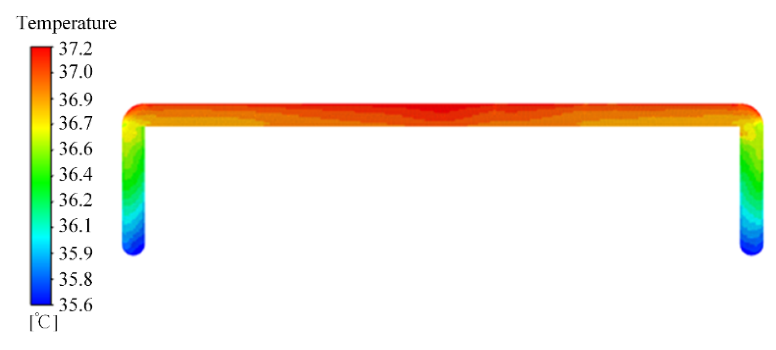
  • The thermal resistance of the annular fixed heat pipe at the end of the winding and the rotating heat pipe at the rotor yoke can be obtained by the temperature difference between the evaporation section and the condensation section of the heat pipe obtained by the CFD simulation above, namely:
    R = T E T c P
    where, Te is the steady-state temperature of the evaporation section of the heat pipe, Tc is the steady-state temperature of the condensation section of the heat pipe, P is the heat load of the evaporation section of the heat pipe, and R is the equivalent thermal resistance of the heat pipe.

3.3. Thermal Resistance Calculation of Other Parts

3.3.1. The Stator Yoke

According to the above thermal network division and node selection inside the motor, it can be seen that the stator yoke mainly contains five heat-transfer paths, which are the stator yoke to the winding, the stator yoke to the shell, the stator yoke to the potting glue, the stator yoke to the stator tooth, and the axial heat conduction of the stator yoke itself.
  • The thermal resistance from the stator yoke to the winding in the slot is R18, R29 and R310. Considering the consistency of thermal resistance, R18 is taken as the analysis object:
    R 18 = d de / 2 λ stj S 18 + d jy λ jy S 18 + d cu / 2 λ cu S 18
    where, λstj is the radial thermal conductivity of the silicon–steel sheet in the stator yoke, λjy is the thermal conductivity of insulation in the slot, λcu is the thermal conductivity of the winding’’s copper wire, dde is the radial thickness of the stator yoke, dcu is the radial thickness of the winding, S18 is the equivalent heat-transfer area between node 1 and node 8, and the same below.
  • Taking the thermal resistance from the stator yoke to shell R133 from node 1 to node 33 as an example:
    R 133 = 1 2 π λ stj l 3 ln r dw r den + 1 2 π λ sh l 3 ln r sh r dw
    where, λSh is the shell thermal conductivity, rden is the inner diameter of the stator yoke, rdw is the outer diameter of the stator yoke, and rsh is the outer diameter of the motor shell.
  • The thermal resistance from the stator yoke to the potting material is R131 and R132, taking R131 as an example:
    R 131 = 1 2 R 12 + 1 λ gf S 131
    where, R12 is the axial thermal resistance of stator yoke, λgf is the thermal conductivity of the potting adhesive, and S131 is the equivalent heat-transfer area between the stator yoke and potting material.
  • The thermal resistances from the stator yoke to stator teeth are R14, R25 and R36. Taking R14 as an example:
    R 14 = ( r dw r dn ) / 2 λ stj S 14
    where, rdn is the inner diameter of the stator.
  • The axial thermal resistance of the stator yoke is R12 and R23. Taking R12 as an example:
    R 12 = l / 3 λ stz S 12
    where, λstz is the axial thermal conductivity of the stator silicon–steel sheet, and l is the axial length of the stator.

3.3.2. The Winding

According to the above division of the motor thermal network and the selection of nodes, it can be seen that there are three main heat-transfer paths of the winding, namely: winding to stator yoke, winding to stator teeth, winding axial thermal resistance.
  • The thermal resistance from the winding to the stator yoke is, taking R81 between node 8 and node 1 as an example:
    R 81 = R 18
  • The thermal resistance from the winding to the stator teeth includes R84, R95, and R106, taking R84 as an example:
    R 84 = d cu / 2 λ cu S 84 + d jy λ jy S 84 + d cu / 2 λ stj S 84
    where, ddc is the radial thickness of stator teeth.
  • The axial thermal resistance of the winding includes R89 and R910, taking R89 as an example:
    R 89 = l / 3 λ cu S 89

3.3.3. The Stator Teeth

According to the above division of the thermal network inside the motor and the selection of nodes, it can be seen that the main heat-transfer paths of the stator teeth are divided into four: thermal resistance from the stator teeth to the stator yoke, thermal resistance from the stator teeth to the winding, axial thermal resistance from the stator teeth and the thermal resistance from the air-gap to the stator teeth.
  • The thermal resistance from the stator teeth to the stator yoke includes R41, R51, and R63. Taking R41 as an example for calculation:
    R 41 = R 14
  • The thermal resistance from the stator teeth to the winding includes R48, R59, and R610, taking R48 as an example:
    R 48 = R 84
  • The axial thermal resistance of stator teeth includes R45 and R56. Taking R45 as an example:
    R 45 = l / 3 λ stz S 45
  • The thermal resistance from stator teeth to air gap includes R426, R526 and R626. Taking R426 as an example:
    R 426 = h st 2 λ stj S 426 + 1 α cq S 426
    where, αcq is the convective heat transfer coefficient between the stator teeth and the air-gap.

3.3.4. The Rotor Boot

There are four primary heat-transfer paths of the rotor boot: rotor boot to air-gap, rotor boot to permanent magnet, rotor boot to rotor yoke, and axial heat conduction of the rotor boot.
  • The thermal resistance from the rotor boot to the air gap includes R1226, R1326 and R1426. Taking R1226 as an example:
    R 1226 = 1 2 π λ stj l / 3 ln r rw r re + 1 α rq S 1226
    where, rrw is the outer diameter of the rotor, rre is the outer diameter of the rotor yoke, and αcq is the convective heat-transfer coefficient between the rotor boot and the air gap.
  • The thermal resistance from rotor boot to the permanent magnet includes R1215, R1316 and R1417. The thermal resistance R1215 is analyzed as an example:
    R 1215 = d pm / 2 λ pm S 1215 + 1 2 π λ stj l / 3 ln r rw r re
    where, λpm is the thermal conductivity of the permanent magnet and dpm is the thickness of the permanent magnet.
  • The thermal resistance from the rotor boot to the rotor yoke includes R1218, R1319 and R1420. Taking R1218 as an example for analysis:
    R 1218 = 1 2 π 180 360 λ stj l / 3 ln r rw r m
    where, rm is the inner diameter of the rotor.
  • The axial thermal resistance inside the rotor boot includes R1213 and R1314. Taking R1213 as an example for analysis:
    R 1213 = l / 3 λ stz S 1213

3.3.5. The Permanent Magnet

There are three main heat-transfer paths of the permanent magnet in the motor: the permanent magnet to the rotor boot, the permanent magnet to rotor yoke and the axial heat conduction of the permanent magnet.
  • The thermal resistance from permanent magnet to rotor boot includes R1512, R1613 and R1714. Taking R1512 as an example for analysis:
    R 1512 = R 1215
  • The thermal resistance from the permanent magnet to the rotor yoke includes R1518, R1619 and R1720. The thermal resistance R1518 is analyzed as an example:
    R 1518 = d pm / 2 λ pm S 1518 + 1 2 π λ stj l / 3 ln r rew r m
  • The axial thermal resistance of permanent magnet includes R1516 and R1617. Taking R1516 as an example for analysis:
    R 1516 = l / 3 λ pm S 1516

3.3.6. The Rotor Yoke

The primary heat-transfer path of the rotor yoke in the motor is divided into three: the rotor yoke to the rotor boot, the rotor yoke to the permanent magnet, and the rotor yoke axial heat conduction.
  • The thermal resistance from the rotor yoke to the rotor boot includes R1812, R1913 and R2014. The thermal resistance R1812 is analyzed as an example:
    R 1812 = R 1218
  • The thermal resistance from the rotor yoke to the permanent magnet includes R1815, R1916 and R2017. The thermal resistance R1815 is analyzed as an example:
    R 1815 = R 1518
  • The axial thermal resistance of the rotor yoke includes R1819 and R1920. Taking R1819 as an example for analysis:
    R 1819 = l / 3 λ stz S 1819

3.4. Solution of Equivalent Thermal Network Model

According to the principle introduced above, the heat conduction thermal resistance and heat convection thermal resistance between each node in the motor were calculated, respectively. Taking the loss of each active node as input, the outflow energy and inflow energy of each node in the motor are equal due to the conservation of energy. Therefore, the thermal balance equation for any node can be obtained by analogy with the node voltage method in the circuit.
G ( i , 1 ) T ( 1 ) + G ( i , i ) T ( i ) G ( i , n ) T ( n ) = P ( i )
where, G (i, i) is the self-thermal conductivity of node i, and the remaining thermal conductivity is the mutual thermal conductivity.
Each node’s heat-balance equations in the thermal network are listed to form a matrix.
[ G ( 1 , 1 ) G ( 1 , i ) G ( 1 , n ) G ( i , 1 ) G ( i , i ) G ( i , n ) G ( n , 1 ) G ( n , i ) G ( n , n ) ] [ T ( 1 ) T ( i ) T ( n ) ] = [ P ( 1 ) P ( i ) P ( n ) ]
that is:
G T = P
where, G is the thermal conductivity matrix, T is the temperature rise matrix, and P is the loss matrix.
The cooling matrix was modeled, and the loss value of each node was substituted into the iterative solution to obtain the temperature rise of each node.

4. The Temperature Field Analysis of Hybrid Heat-Pipe Cooling PMSM for EVs

4.1. Hybrid Heat-Pipe Cooling PMSM for Evs

Based on the equivalent thermal network proposed in this paper, the temperature field calculation of a hybrid heat-pipe cooling PMSM for Evs was analyzed. The main parameters of the PMSM are shown in Table 1. The rated speed is 4000 rpm, the maximum speed is 12,000 rpm, and the maximum output torque is 380 Nm. The material properties of the potting glue used to enhance the heat-transfer efficiency of the winding end are shown in Table 3. The material properties of the main modeling areas involved in the motor are shown in Table 4.
This article analyzed the losses of various heating components in the motor before calculating the temperature field using an equivalent thermal network. The various losses in the motor mainly included copper loss, iron loss, permanent magnet eddy current loss, and mechanical loss. Due to the fact that the iron loss of the motor was mainly related to the harmonic magnetic field during actual operation, and, in order to make the subsequent calculation results of the motor’s equivalent thermal network more accurate, this article used non-sinusoidal excitation collected from the actual inverter for loss analysis. The corresponding losses of each node in the equivalent thermal network under non-sinusoidal excitation under three operating conditions are shown in Table 5. As is shown in Table 5, the losses of the motor under three typical working conditions were obtained by electromagnetic FEA and an empirical formula, respectively.

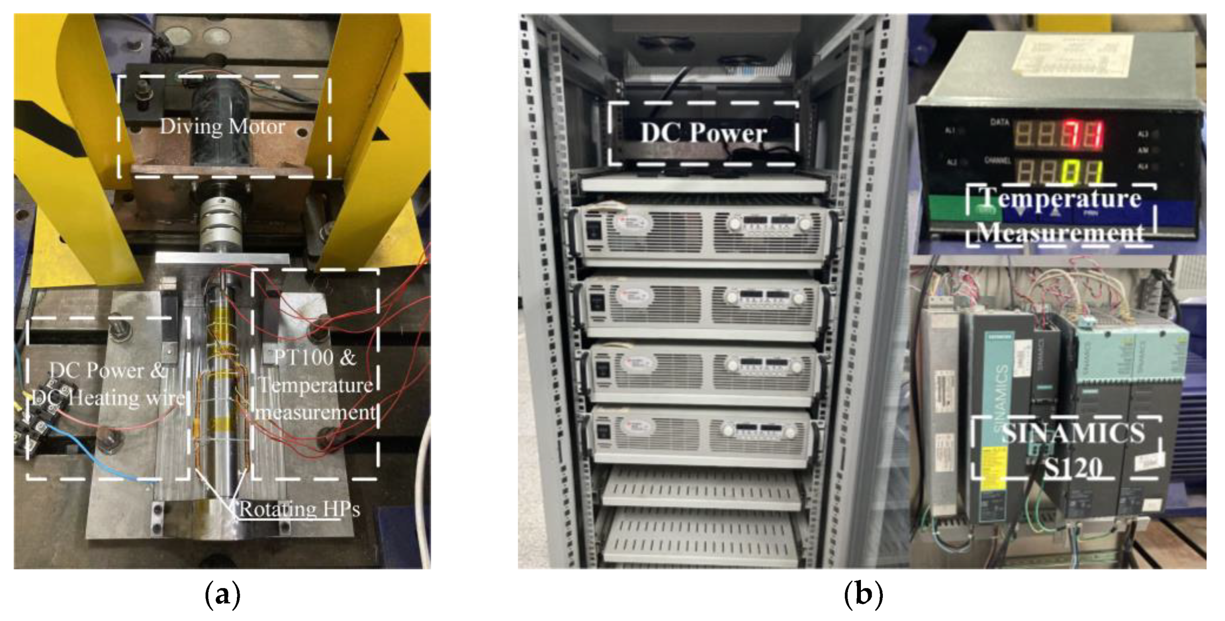
4.2. Equivalent Thermal Conductivity Experiment of Heat Pipe

The equivalent thermal conductivity of the heat pipe is obtained by designing a reasonable equivalent experiment to calculate the contact thermal resistance further accurately. The experimental platform is shown in Figure 7, including drive motor, PT100 thermocouple, rotating hollow shaft, DC heating wire, etc. This paper mainly analyzes the equivalent thermal conductivity of the rotating heat pipe at different speeds of the motor under the same thermal load of 200 W. The main principle of the experiment is to fix the U-shaped rotating heat pipe on the rotating shaft. By measuring the temperature difference between the evaporation section and the condensation section of the rotating heat pipe at different speeds, the equivalent thermal conductivity of the rotating heat pipe can be calculated by introducing the formula (34–35).
R = T E T c p
Φ = Δ t 1 A k = Δ t R
where, Φ is the heat flux transmitted through the heat pipe, Te is the steady-state temperature of the evaporation section of the heat pipe, Tc is the steady-state temperature of the condensation section of the heat pipe, P is the heat load of the evaporation section of the heat pipe, Δt represents the average temperature difference between the evaporation and condensation section, R is the equivalent thermal resistance of the heat pipe, k is the equivalent heat transfer coefficient of the heat pipe, and A is the equivalent contact area of the heat pipe.
The experimental data of the equivalent thermal conductivity of the heat pipe are shown in Table 6. When the heat load of the rotor is constant, the thermal conductivity of the rotating heat pipe increases first, then decreases, and finally increases again with the increase of the rotor speed. The highest thermal conductivity can reach 76,804.9 W/m·k at 4000 rpm.
As shown in Table 7, the equivalent thermal conductivity of the heat pipe obtained by the CFD simulation iwa compared with the conclusion of the equivalent experimental calculation designed in this paper. It can be seen that the thermal conductivity of the rotating heat pipe obtained by the CFD simulation is low, which is due to the fact that CFD cannot effectively simulate the liquid working medium provided by the wick structure inside the heat pipe to further accelerate the reflux effect when simulating the rotating heat pipe.

4.3. Equivalent Thermal Conductivity Experiment of Heat Pipe

Aimed at the cooling matrix equation proposed above, the iterative calculation of the temperature rise was solved in each modeling area under three working conditions of the rated condition, maximum speed and maximum torque. The iterative calculation time of the program was between 105–194 s under the three working conditions. The temperature rise calculation results of each modeling area under non-sinusoidal excitation are shown in Table 8.
Subsequently, the CFD method was used to calculate the temperature field of the hybrid heat-pipe cooling motor to verify the effectiveness of the proposed calculation method based on the equivalent thermal network method. When the motor is at rated and maximum speed conditions, the k-epsilon classical turbulence model and the standard wall function are used to compensate for the grid-quality degradation caused by the complex shape inside the motor and the double-layer full y + processing to compensate for the grid-quality degradation caused by the complex shape of the motor during the simulation of the turbulence model. For the maximum torque condition, the fluid state in the air-gap can be judged as a laminar flow state according to the Reynolds number calculated by the air-gap, so the classical laminar flow model and the standard wall function were used for the simulation calculation. The radiation heat process was ignored because of its lower inference in terms of the temperature field calculation.
Based on the loss analysis and internal fluid state analysis of permanent magnet synchronous motors for hybrid heat-pipe cooled electric vehicles mentioned above, the CFD method was used to verify the accuracy of the proposed equivalent heat network method calculation results. The comparison is shown in Table 8. The temperature distribution nephogram of each heating component in the motor under three working conditions under non-sinusoidal excitation is shown in Figure 8. According to Table 8, it can be seen that the maximum error is within 3.2%, and the error mainly occurs at the end winding. This is mainly because the influence of the low thermal conductivity of the potting material was ignored in modeling the equivalent effect thermal network. After analysis, it can be considered that the error of the equivalent thermal network model established in this article is within an acceptable range.

5. Conclusions

In this paper, the equivalent thermal network method was used to analyze and calculate the temperature field of the hybrid heat-pipe cooling permanent magnet synchronous motor for electric vehicle with a rated power of 90 kw. The equivalent thermal conductivity of the rotating heat-pipe structure was obtained by the equivalent experiment. The temperature calculation results of each node under three typical conditions of rated condition, maximum torque condition, and maximum speed condition were compared with the simulation analysis results, and the following conclusions were obtained:
  • The equivalent thermal resistance of the rotating heat pipe decreases first, then increases, and finally decreases with the increase of the rotor rotation speed when the thermal load is constant. The thermal resistance is low at the rated speed of 4000 rpm, and the maximum equivalent thermal conductivity can reach 76,804.9W/m·k;
  • By establishing an equivalent thermal network for the motor, the temperature of each node was analyzed and calculated. When comparing the calculation results with the CFD simulation results, it was found that the temperature error of each node was within 5%, which is within the acceptable range. In view of the error, the analysis in this paper was mainly due to the complex shape of the cooling structure of the rotating heat pipe and the cooling structure of the heat pipe at the end winding, and the existence of potting glue between the end winding and the fixed heat pipe, which affects the accuracy of the thermal resistance calculation, so there is a certain error in the calculation results;
  • In this paper, by comparing the temperature field calculation method of hybrid heat-pipe cooling motor based on equivalent thermal network with the traditional CFD simulation time, it was found that the iteration time of the proposed calculation method is within 194 s, which greatly shortens the temperature field calculation time of the hybrid heat-pipe cooling PMSM for EVs.
The equivalent thermal network method can be used to quickly calculate the temperature field distribution inside the hybrid heat-pipe cooling structure PMSM under the premise of ensuring a certain accuracy, which will be valuable as a reference for the related research of heat-pipe cooling structure motors in the future.

Author Contributions

Conceptualization, H.W.; methodology, H.W. and C.Z.; software, C.Z.; validation, C.Z.; formal analysis, C.Z.; investigation, L.G.; resources, H.W. and W.C.; data curation, L.G.; writing—original draft preparation, C.Z.; writing—review and editing, H.W. and Z.Z.; visualization, H.W. and Z.Z.; supervision, W.C.; project administration, W.C.; funding acquisition, H.W. and L.G. All authors have read and agreed to the published version of the manuscript.

Funding

This research was funded by “National Natural Science Foundation of China, grant number 52277064” and “Zhejiang Provincial Natural Science Foundation of China, grant number LY22E070005”.

Data Availability Statement

The data presented in this study are available in the article.

Conflicts of Interest

There is no conflict of interest.

References

  1. Wang, X.; Li, B.; Gerada, D.; Huang, K.; Stone, I.; Worrall, S.; Yan, Y. A critical review on thermal management technologies for motors in electric cars. Appl. Therm. Eng. 2022, 117758, 1359–4311. [Google Scholar] [CrossRef]
  2. Gronwald, P.O.; Kern, T.A. Traction Motor Cooling Systems: A Literature Review and Comparative Study. IEEE Trans. Transp. Electrif. 2021, 7, 2892–2913. [Google Scholar] [CrossRef]
  3. Dan, D.; Yao, C.; Zhang, Y.; Zhang, H.; Zeng, Z.; Xu, X. Dynamic thermal behavior of micro heat pipe array-air cooling battery thermal management system based on thermal network model. Appl. Therm. Eng. 2019, 162, 114183. [Google Scholar] [CrossRef]
  4. Vese, I.; Marignetti, F.; Radulescu, M.M. Multiphysics approach to numerical modeling of a permanent-magnet tubular linear motor. IEEE Trans. Ind. Electron. 2010, 57, 320–326. [Google Scholar] [CrossRef]
  5. Boglietti, A.; Cavagnino, A.; Staton, D.; Shanel, M.; Mueller, M.; Mejuto, C. Evolution and modern approaches for thermal analysis of electrical machines. IEEE Trans. Ind. Electron. 2009, 56, 871–882. [Google Scholar] [CrossRef]
  6. Tessarolo, A.; Bruzzese, C. Computationally efficient thermal analysis of a low-speed high-thrust linear electric actuator with a three-dimensional thermal network approach. IEEE Trans. Ind. Electron. 2015, 62, 1410–1420. [Google Scholar] [CrossRef]
  7. Nerg, J.; Rilla, M.; Pyrhonen, J. Thermal Analysis of Radial-Flux Electrical Machines with a High Power Density. IEEE Trans. Ind. Electron. 2008, 55, 3543–3554. [Google Scholar] [CrossRef]
  8. Si, J.; Zhao, S.; Feng, H.; Hu, Y.; Cao, W. Analysis of temperature field for a surface-mounted and interior permanent magnet synchronous motor adopting magnetic-thermal coupling method. CES Trans. Electr. Mach. Syst. 2018, 2, 166–174. [Google Scholar] [CrossRef]
  9. Li, L.; Zhang, J.; Zhang, C.; Yu, J. Research on Electromagnetic and Thermal Issue of High-Efficiency and High-Power-Density Outer-Rotor Motor. IEEE Trans. Appl. Supercond. 2016, 26, 5204805. [Google Scholar] [CrossRef]
  10. Zhang, B.; Qu, R.; Xu, W.; Wang, J.; Chen, Y. Thermal model of totally enclosed water-cooled permanent magnet synchronous machines for electric vehicle applications. In Proceedings of the 2014 International Conference on Electrical Machines (ICEM), Berlin, Germany, 2–5 September 2014; pp. 2205–2211. [Google Scholar] [CrossRef]
  11. Xiao, S.; Griffo, A. Online thermal parameter identification for permanent magnet synchronous machines. Electr. Power Appl. 2020, 14, 2340–2347. [Google Scholar] [CrossRef]
  12. Huang, J.; Naini, S.S.; Miller, R.; Rizzo, D.; Sebeck, K.; Shurin, S.; Wagner, J. A Hybrid Electric Vehicle Motor Cooling System—Design, Model, and Control. IEEE Trans. Veh. Technol. 2019, 68, 4467–4478. [Google Scholar] [CrossRef]
  13. Liang, D.; Zhu, Z.Q.; Zhang, Y.; Feng, J.; Guo, S.; Li, Y.; Wu, J.; Zhao, A. A hybrid lumped-parameter and two-dimensional analytical thermal model for electrical machines. IEEE Trans. Ind. Appl. 2020, 57, 246–258. [Google Scholar] [CrossRef]
  14. Zhang, C.; Zhang, X.; Zhao, F.; Gerada, D.; Li, L. Improvements on Permanent Magnet Synchronous Motor by Integrating Heat Pipes into Windings for Solar Unmanned Aerial Vehicle. Green Energy Intell. Transp. 2022, 1, 100011. [Google Scholar] [CrossRef]
  15. Liu, L.; Tan, G.; Zhou, F.; Sun, M.; Liu, Z.; Yang, C. A Study on Heat Dissipation of Electric Vehicle Motor Based on Heat-Pipe Heat Transfer Analysis. SAE Technical Paper, 6 April 2021. [Google Scholar]
  16. Sun, D.; Xu, J.; Chen, Q. Modeling of the evaporation and condensation phase-change problems with FLUENT. Numer. Heat Transf. Part B Fundam. 2014, 66, 326–342. [Google Scholar] [CrossRef]
  17. Sun, Y.; Zhang, S.; Chen, G.; Tang, Y.; Liang, F. Experimental and numerical investigation on a novel heat pipe based cooling strategy for permanent magnet synchronous motors. Appl. Therm. Eng. 2020, 170, 114970. [Google Scholar] [CrossRef]
  18. Liang, F.; Gao, J.; Li, F.; Xu, L.; Wang, Z.; Jiang, H. A central cooling structure for motorized spindles: Principle and application. In Proceedings of the 2019 18th IEEE Intersociety Conference on Thermal and Thermomechanical Phenomena in Electronic Systems (ITherm), Las Vegas, NV, USA, 28–31 May 2019; pp. 1204–1211. [Google Scholar]
  19. Chang, S.W.; Hsieh, M.F.; Wu, P.S.; Cai, W.L. Convective heat transfer motivated by liquid-to-vapor density difference in centrifugal force field of axially rotating loop thermosyphons. Processes 2021, 9, 1909. [Google Scholar] [CrossRef]
  20. Wan, Z.; Sun, B.; Wang, X.; Wen, W.; Tang, Y. Improvement on the heat dissipation of permanent magnet synchronous motor using heat pipe. Proc. Inst. Mech. Eng. Part D J. Automob. Eng. 2020, 234, 1249–1259. [Google Scholar] [CrossRef]
  21. Zhu, Z.Q.; Pang, Y.; Howe, D.; Iwasaki, S.; Deodhar, R.; Pride, A. Analysis of electromagnetic performance of flux-switching permanent-magnet machines by nonlinear adaptive lumped parameter magnetic circuit model. IEEE Trans. Magn. 2005, 41, 4277–4287. [Google Scholar] [CrossRef]
  22. Mellor, P.H.; Roberts, D.; Turner, D.R. Lumped parameter thermal model for electrical machines of TEFC design. IEE Proc. B (Electr. Power Appl.) 1991, 138, 205–218. [Google Scholar] [CrossRef]
  23. Demetriades, G.D.; de la Parra, H.Z.; Andersson, E.; Olsson, H. A real-time thermal model of a permanent-magnet synchronous motor. IEEE Trans. Power Electron. 2010, 25, 463–474. [Google Scholar] [CrossRef]
  24. Park, J.B.; Moosavi, M.; Toliyat, H.A. Electromagnetic-thermal coupled analysis method for interior PMSM. In Proceedings of the 2015 IEEE International Electric Machines & Drives Conference (IEMDC), Coeur d’Alene, ID, USA, 10–13 May 2015; pp. 1209–1214. [Google Scholar]
  25. Menter, F. Two-equation Eddy-viscosity Turbulence Models for Engineering Applications. AIAA J. 1994, 32, 1598–1605. [Google Scholar] [CrossRef]
  26. Howey, D.A.; Childs PR, N.; Holmes, A.S. Air-gap convection in rotating electrical machines. IEEE Trans. Ind. Electron. 2010, 59, 1367–1375. [Google Scholar] [CrossRef]
  27. Wang, H.; Liu, X.; Kang, M.; Guo, L.; Li, X. Oil injection cooling design for the IPMSM applied in electric vehicles. IEEE Trans. Transp. Electrif. 2022, 8, 3427–3440. [Google Scholar] [CrossRef]
Figure 1. Schematic diagram of hybrid heat-pipe cooling structure.
Wevj 14 00141 g001
Figure 2. Cloud diagram of the volume fraction of the working mass inside the rotating heat pipe.
Wevj 14 00141 g002
Figure 3. Cloud diagram of temperature distribution of rotating heat pipe.
Wevj 14 00141 g003
Figure 4. Thermal network establishment flowchart.
Wevj 14 00141 g004
Figure 5. Node distribution in the motor.
Wevj 14 00141 g005
Figure 6. Schematic diagram of heat-conduction principle on the cylinder wall.
Wevj 14 00141 g006
Figure 7. Equivalent thermal conductivity experimental equipment: (a) experimental platform; and (b) drive and measuring equipment.
Wevj 14 00141 g007
Figure 8. Temperature field under non-sinusoidal excitation: (a) rated condition; (b) maximum speed condition; and (c) maximum torque condition.
Wevj 14 00141 g008
Table 1. Parameter of hybrid heat-pipe cooling motor.
ParameterDateParameterDate
Rated power90 kWPole-Slot number8p48s
Rated torque215 NmPitch5
Rated speed4000 r/minStator yoke diameter144 mm
Peak Power160 kWRotor yoke diameter48 mm
Maximum torque380 NmAir gap length0.5 mm
Maximum speed12000 r/minPolar arc coefficient0.64
DC Bus Voltage320 VInsulation levelH
Table 2. Heat-pipe equivalent thermal conductivity simulation data.
Motor Speed
(rpm)
Thermal Resistance
(°C/W)
Thermal Conductivity (W/m·k)
00.01823,560.3
6000.02318,723.8
40000.00674,628.2
Table 3. Potting material properties.
PropertyUnitDate
Thermal conductivityW/m·k3.2–3.4
Breakdown voltagekV/mm≥15
Working temperature°C−55–180
Table 4. Modeling area and material properties.
Modeling AreaMaterialThermal Conductivity (W/m·k)
ShellIron39.2
Stator yoke (radial/axial)Silicon steel sheet38.7/3.7
Rotor (radial/axial)Silicon steel sheet38.7/3.7
WindingCopper385
Slot insulationInsulating paper0.2
Permanent magnetNd-Fe-B9
ShaftSteel42
BearingSteel42
CavityAir0.026
Table 5. The loss value of each node of the motor under non-sinusoidal excitation.
NodeLoss at Rated Condition (W)Loss at Maximum Torque Condition (W)Loss at Maximum Speed Condition (W)
1–3254.2623.12147.53
7–116749.915,835.86145.6
4–6484.57123766.97
12–1432.412.5126.75
18–2052.411.1200.7
15–1711.15.829.3
21–22126.118.9432
Table 6. Experimental data of equivalent thermal conductivity of heat pipe.
Motor Speed
(rpm)
Temperature (°C)Thermal Resistance
(°C/W)
Thermal Conductivity (W/m·k)
TcTe
0109.78113.370.01825,601.6
60016.9521.620.02320,036.1
120022.7125.120.01238,402.5
180024.9628.450.01727,107.6
240026.4030.310.01924,254.2
300030.4133.620.01628,801.8
360032.5934.960.01238,402.5
400035.1436.400.00676,804.9
Table 7. Comparison of thermal conductivity of rotating heat pipe.
Speed
(rpm)
Equivalent Experiments
(W/m·k)
CFD Calculations
(W/m·k)
025,601.623,560.3
400076,804.974,628.2
Table 8. Non-sinusoidal excitation temperature comparison.
Operating ConditionsCalculation MethodWinding StatorPMRotor
Rated conditionThermal network89.34 °C44.32 °C35.12 °C33.98 °C
CFD86.48 °C45.4 °C35.54 °C34.33 °C
Error3.2%2.4%1.2%1%
Maximum torque conditionThermal network141.8245.6227.1227.09
CFD138.7746.5527.827.62
Error2.2%2%2.4%2%
Maximum speed conditionThermal network87.6249.2737.1133.98
CFD85.2649.8137.7234.59
Error2.7%1.1%1.6%1.8%
Disclaimer/Publisher’s Note: The statements, opinions and data contained in all publications are solely those of the individual author(s) and contributor(s) and not of MDPI and/or the editor(s). MDPI and/or the editor(s) disclaim responsibility for any injury to people or property resulting from any ideas, methods, instructions or products referred to in the content.

