
Framework and Classification of Battery System Architectures


Abstract
:1. Introduction
2. Materials and Methods
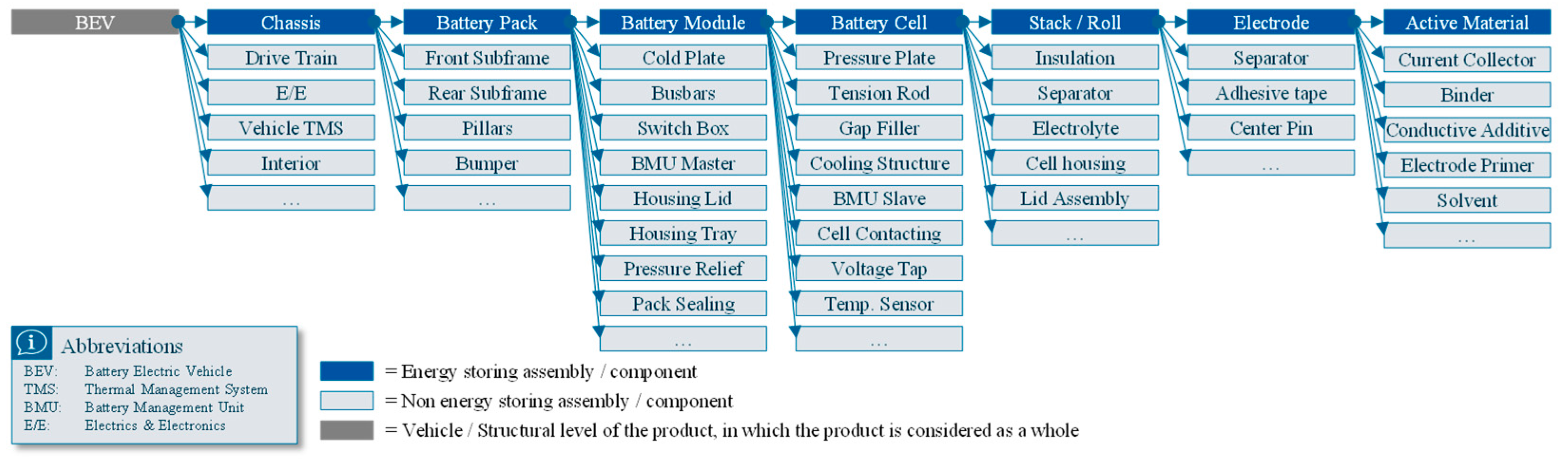
2.1. System Levels
- “Active materials is used as a collective term for materials that react chemically to produce, store or release electric energy inside the battery cell” [16] (p. 64). It is therefore defined as the lower limit of the system levels to be considered in this paper.
- “Electrode, electrically connected to one terminal of a cell, in electric contact with the electrolyte of that cell and on which the electrode reaction occurs” [17].
- Electrode stack (stack)/jelly roll (roll) is an assembly of stacked/rolled battery electrode sheets (anodes and cathodes) with the separator in between [18]. The electrode stack/jelly roll is considered the minimum viable functional system level in combination with the electrolyte.
- “(Battery) cell means a single encased electrochemical unit containing one positive and one negative electrode which exhibits a voltage differential across its two terminals” [19].
- “Battery module means a set of battery cells that are connected together or encapsulated within an outer casing to protect the cells against external impact, and which is meant to be used either stand-alone or in combination with other modules” [16] (p. 64).
- Battery pack is an “Energy storage device that includes cells or cell assemblies connected with cell electronics, high voltage circuit and over current shut-off device including electrical interconnections, interfaces for external systems (e.g., cooling, high voltage, auxiliary low voltage and communication)” [20].
- Battery system is an “Energy storage device that includes cells or cell assemblies or battery pack(s) as well as electrical circuits and electronics (e.g., BCU, contactors)” [20].
- Chassis/body in white (BiW) is the outer shell of the battery electric vehicle (BEV) [21] (p. 3).
- “A Battery Electric Vehicle or BEV is a vehicle that uses a battery as the sole means of energy storage for the propulsion of the vehicle” [22]. The BEV is therefore the highest possible layer considered in this paper, in which the product is considered as a whole.
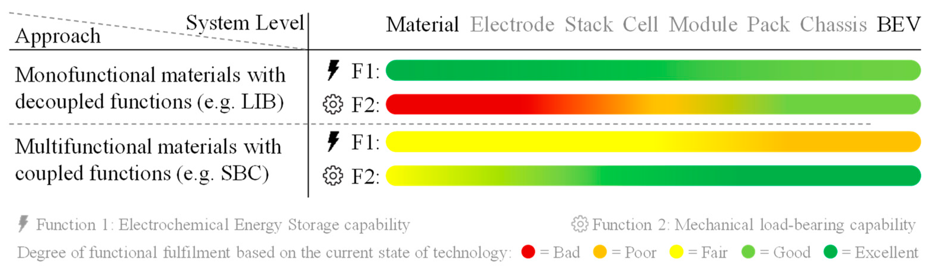
2.2. Mono- vs. Multifunctional Materials
2.2.1. Monofunctional Materials with Decoupled Functions
2.2.2. Multifunctional Materials with Coupled Functions
2.2.3. Comparison of Mono- and Multifunctional Materials
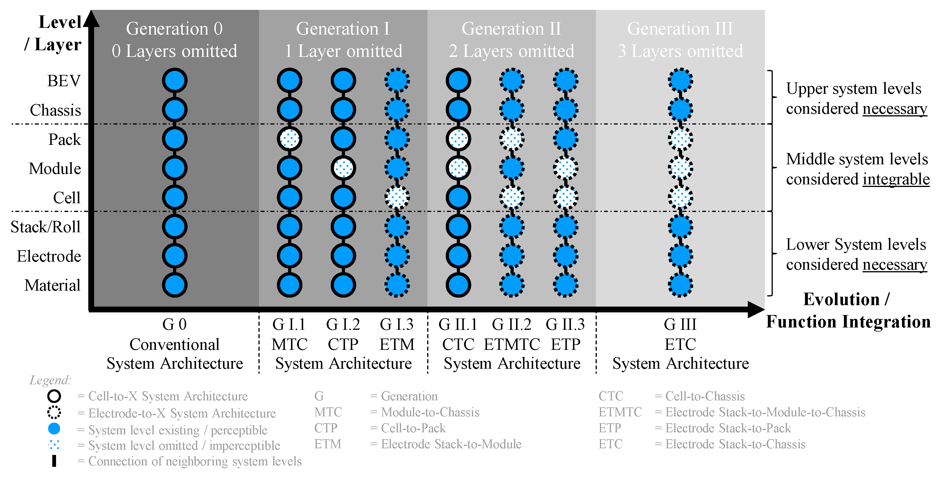
3. Results
3.1. Generation 0—0 Layers Omitted
3.1.1. Generation 0—Conversion Design
- Nomenclature: The first generation of LIB mass market BEVs was based on the conversion of existing internal combustion engine (ICE) vehicle platforms, leading to the nickname “Conversion Design” [38] (p. 54).
- Approach: To save both investments in development and production cost, the already developed ICE chassis/vehicle platform as well as the existing production lines were used to build the first BEVs. This leads to significantly lower costs and risks for the manufacturer, but to disadvantages in the technical implementation, as innovations and package advantages can only be achieved within limits.
- Omitted Components: Compared to vehicles with combustion engines, the ICE is replaced by an electric drive train.
- Industry Examples: The arguably first highway legal serial production of an all-electric car to use lithium–ion battery cells was the Tesla Roadster 2008 [39], which was partly based on a Lotus Elise platform, even though they did not share the same production line [40]. Another well-known example is the e-Golf, which VW assembled on the same production line in Wolfsburg as the Golf combustion models [41]. In the early 2020s, there are still many models available with both combustion engines and pure battery electric vehicles (BEVs). These include, among others BMW 4, 7, X1 and X3 [42]; Citroën C4 [43]; DS 3 Crossback [44]; Fiat 500 [45]; Hyundai Kona [46]; Mini [47]; Opel Corsa, Mokka and Zafira [48]; Peugeot 208, 2008 and Traveller [49]; Renault Master [50]; Toyota Proace and Verso [51]; Volvo XC40 [52], VW e-up [53].
3.1.2. Generation 0—Purpose Design
- Nomenclature: Instead of converting existing ICE vehicles, the next generation system architecture is a dedicated “Purpose Design” BEV platform, often executed as a skateboard platform [54].
- Approach: The Purpose Design platforms aim to exploit the advantages of electric drive trains. Battery systems no longer have to be squeezed into existing installation spaces, but the platform design is optimized for a purely electric powertrain—a dedicated EV platform.
- Omitted Components: New degrees of freedom result from the elimination of the vehicle tunnel, which enables a considerably simplified vehicle underbody and thus also simplified operating equipment in the area of chassis construction [38] (p. 55). By eliminating the combustion engine, the wheelbase can be extended to gain more space between the axles and accommodate a larger battery in the underbody of the vehicle. [55] In comparison with different BEV conversion designs, it can be argued that the multi-pack variants are omitted. Instead of electrically connecting two mechanically separated battery packs to form one battery system, as in the conversion design of the 2015 FORD Focus EV [56], for Purpose Design platforms there is predominantly only one installation space for the battery system. This reduces the number of pack housings from two to one and also lowers the number of necessary thermal and electrical interfaces (connectors).
- Industry Examples: Generation 0 in the purpose design manifestation can be considered as state-of-the-art in 2023, as the BEVs in mass production are predominantly based on purpose design architectures with all system levels. Examples include Geely SEA platform [57], Hyundai E-GMP [58], Rivian Skateboard [59], Tesla [60], Volkswagen Group MEB platform [61] and Xpeng SEPA [62], among others.
3.2. Generation I—1 Layer Omitted
3.2.1. Generation I.1—Module-to-Chassis
- Nomenclature: The “Generation I.1” expression is based on the partly omission of the pack/system level. Based on the nomenclature defined in the introduction of this chapter, Generation I.1 can be described with the nickname “Module-to-Chassis”.
- Approach: Cells are assembled into modules and these are then integrated into the vehicle chassis (parts). Previously separate pack and chassis components can be brought closer together/combined, such as the battery pack lid with the chassis base. It is possible to integrate former pack functionalities/components into the underlying assembly group—the battery module. The pack level is partially omitted, as probably not all pack components can be merged with components of other levels. Examples for components that cannot be easily transferred to other system levels can be found in the pack domains of the thermal system and high-voltage. The pack component groups of the temperature control system (cooling and heating elements) and the battery junction box (contactors, fuses, currents sensors, BMU master, etc.) can be partially moved from the pack level to the neighboring module or chassis level on paper, but only lead to an increase in energy density if they are intelligently functionally integrated.
- Omitted Components: The battery pack housing and the vehicle chassis merge into one component/assembly.
- Industry Examples: Until the beginning of 2023, there are no announcements for Module-to-Chassis system architectures.
3.2.2. Generation I.2—Cell-to-Pack
- Nomenclature: “Generation I.2” partly skips the module level. Cells are directly integrated into the pack housing, which is then married to the chassis—a “Cell-to-Pack” system architecture. In the existing literature, this approach is also known under the description “module-less” [63] or “module-free” [64] battery pack technology.
- Approach: “Cell-to-Pack” describes a new type of structure of battery systems, which is characterized by the direct integration of the battery cells into the battery pack [13]. This allows for the reduction in the passive/non-energy storing components of the battery module. Inside this Generation I.2, different types of execution can be observed. Some manufacturers only eliminate the module housings, but preserve cell sub-assemblies, while other manufacturers rely on one complete cell block (cf. industry examples).
- Omitted Components: Incremental improvements can be observed by omitting the module housing [12]. The functions of the module housing, e.g., the mechanical clamping of pouch and prismatic cells, are no longer carried out by module pressure plates and module tie rods, but instead are achieved on the high pack level [65]. The previously required fastening of the individual modules as well as the space needed around these modules in order to be able to integrate them into the pack housing can be significantly reduced; thus, the cells can be packed in a denser manner and a higher overall system energy density is achieved. The saved parts also lead to a cost reduction.
- Industry Examples: Multiple cell manufactures as well as leading vehicle original equipment manufacturers (OEMs) have filed patents for Cell-to-Pack system architectures, announced plans for a product market launch or already have a product in production. These companies are, among others, BYD (Patent 2019 [65]—Announcement 2020 [66]); CATL (2019 [67], 2022 “CTP 3.0 battery “Qilin” [68]); LG Chem (2020 [69]); Mercedes-Benz Group (2020 [70]); Nio (2020 [71]); Stellantis (2021 [72]); SVOLT (2021 [73] & 2022 [74]); Tesla (2020 [75]) and Volkswagen Group (2021 [76]).
3.2.3. Generation I.3—Electrode Stack-to-Module
- Nomenclature: “Generation I.3” skips the classic battery cell and is called “Electrode Stack-to-Module” system architecture based on the neighboring system levels of the skipped battery cell level.
- Approach: Instead of building individual cells, a battery module is built up directly out of electrode stacks. Lithium–ion battery cells based on LNMC/LNCA cathodes exhibit a typical nominal voltage of around 3.6 to 3.7 V or 3.2 Volts if the cathode is based on LFP. A key performance indicator of the Electrode Stack-to-Module approach therefore is a larger voltage difference between the two module terminals, in the region of current battery modules, i.e., 7.2–59.2 V (nominal). Starter batteries in ICE vehicles are predominantly lead–acid batteries and can be described as an approximation to the Electrode-to-Module approach, as the individual cells do not have their own fully enclosed housing, but the 12 V lead acid battery consists of multiple serially connected electrode sets, which are separated by insulation walls [77] (pp. 247–264). A similar approach is conceivable for an advanced battery chemistry in which the inner jelly rolls/electrode stacks of a battery are not (only) connected in parallel, but (also) in series. Liquid electrolytes of current LIBs decompose under voltage differences higher than 4.2 V [78], which is why until now no industry implementation of LIB-based ETM system architectures can be found. However, next gen solid-state electrolytes can resist higher voltage differences and therefore enable bipolar stacking/a serial connection of the individual monocells [79,80].
- Omitted Components: The passive battery cell/module housing material is significantly reduced, which leads to a better ratio of cell housing mass to active material mass. If bipolar electrodes are used, the external wiring (tabs and wires) of the individual electrode stack can be omitted, as all electrodes are connected in series and only the two tabs at the end of the stack need to be connected [81].
- Industry Examples: By early 2023, there are different announcements for electrode stack-to-module system architectures based mainly on solid-state electrolytes, but no systems in series production, e.g. the company ProLogium announced an EV battery pack based on solid-state technology and describe their approach as “Cell is Modul (CIM)” [82]. Additionally, the first research results provide an impression of what an implemented approach may look like [81,83,84].
3.3. Generation II—2 Layers Omitted
3.3.1. Generation II.1—Cell-to-Chassis
- Nomenclature: “Generation II.1” is known as “Cell-to-Chassis” (CTC). By (partly) avoiding the module and the pack level, the battery cells are directly integrated into the chassis. Therefore, this approach is also known under the nicknames “Cell-to-Body” (CTB) referring to the body in white, “Cell-to-Vehicle” (CTV), “Cell-to-Car”(CTC) [85] or “Cell-to-Frame” (CTF) [86]. Since the battery cell and chassis levels are considered necessary for conventional LIB cells, Generation II.1 represents the methodological limit of what can be achieved with conventional battery cells by omitting the system levels in the vehicle.
- Approach: The functions previously taken over by the module and pack have to be redistributed to the remaining system levels. The degree of function integration increases parallel to the decrease in the number of system levels. The module and pack housing functionalities have either to be taken over by the chassis or by the cell. The cells are mechanically connected to the chassis and contribute significantly to their stiffness, which is why the system is also called a “Structural Battery Pack” [87]. The difference to the previously described Cell-to-Pack approach lies in the interface between the pack and the chassis, whereas with a CTP the battery system can still be detached from the chassis and the vehicle interior without leaving a hole in the bottom of the vehicle chassis. With CTC technology, the interior components (e.g., the seats) are directly connected to the battery system lid, which leads to challenges during the disassembly [88]. Current announcements by manufacturers are limited to the integration of cells into the vehicle floor. The integration of cells into the cavities of adjacent body components, such as the A-, B-, C-pillars or the doors, has not been announced. The reasons can be found, among other things, in the safety of LIBs in the event of a crash. As the key technology battery cell increasingly merges with the entire vehicle, this leads to changes in the development process. Due to the significantly higher system energy density of the CTX approaches, a development focus lies in the field of battery system safety, and more specifically in the topics of cell selection, gas flow and thermal propagation prevention. Due to the increased mechanical integration of the cells, repairs become more challenging [89], which must lead to higher quality requirements to prevent field failures due to a lack of repair capability.
- Industry Examples: In recent years, there has been an increase in announcements and implementations in the field of CTC technology. These include, among others, BMW [86]; BYD [90]; CATL [91]; Leapmotor [92,93] and Tesla [88]. As the volumetric system energy density of Generation II is significantly improved over Generation 0, it paves the way for alternative battery chemistries that have lower volumetric energy density at the cell level and are therefore not yet considered a viable option for long-range BEVs, but excel in other areas such as safety, cost, sustainability and cycle life, e.g., sodium–ion batteries (SIB) and lithium iron phosphate (LFP) batteries.
3.3.2. Generation II.2—Electrode Stack-to-Module-to-Chassis
- Nomenclature: “Generation II.2” is an “Electrode Stack-to-Module-to-Chassis” system architecture.
- Approach: This G II.2 pursues the idea of skipping the cell level and then integrating these battery modules into the vehicle chassis. Therefore, this approach is a combination of the previously introduced Generations G I.1, Module-to-Chassis, and G I.3; Electrode Stack-to-Module.
- Omitted Components: Battery cell housings and merging of pack housing and chassis.
- Industry Examples: Until 2023, there are no announcements for Electrode Stack-to-Module-to-Chassis system architectures. This generation can only be expected after the previous generations G I.1—MTC and G I.3—ETM have been successfully implemented.
3.3.3. Generation II.3—Electrode Stack-to-Pack
- Nomenclature: “Generation II.3” is an “Electrode Stack-to-Pack” system architecture.
- Approach: The G I.3—Electrode-to-Module system architecture idea is taken and developed on step further by aiming to build up system level characteristics coming from an electrode stack level.
- Omitted Components: The cell housings as well as the module housings are (partly) omitted.
- Industry Examples: Until 2023, there are no announcements for electrode stack-to-pack system architectures. Nevertheless, there are patents that could be interpreted in this direction [94].
3.4. Generation III—3 Layers Omitted
Generation III—Electrode Stack-to-Chassis
- Nomenclature: “Generation III” is an “Electrode Stack-to-Chassis” system architecture.
- Approach: G III is enabled by realizing the electrochemical energy storage function as a chassis component or the other way around. The extreme approach combines the previously separate levels of the battery cell and the chassis components. One way of approaching this highly function-integrated Generation would be to use SBC electrode stacks surrounded only by the matrix material of the carbon-fiber-reinforced polymer (CFRP). This drastically reduces the number of housings/intermediate system layers—the active material housing is concurrently the chassis component. Decentralized segments of body structure/panels can be electrically connected to form the entire battery system.
- Omitted Components: Components of the classic battery system with predominantly mechanical functionality, such as cell, module and pack housings, will be (partly) omitted. The electrical interface between the battery system and the vehicle (BMU, contactors, etc.) will be probably retained in part.
- Industry Examples: Until 2023, there are no announcements for electrode stack-to-chassis system architectures. Nevertheless, different research teams are working on structural integrated LIBs [95] as well as structural battery composites [32], which could lead to viable products in the future. As the ETC cost would be high at the beginning, an application in the aviation or even aerospace industry is initially more likely than in the car industry [96].
4. Discussion
Author Contributions
Funding
Data Availability Statement
Conflicts of Interest
References
- Kroher, T.; Wieler, J. Kostenvergleich e-Fahrzeuge + Plug-In Hybride Gegen Benziner und Diesel. Available online: https://assets.adac.de/Autodatenbank/Autokosten/E-AutosVergleich.pdf (accessed on 15 March 2023).
- Bühler, J.; Goebelt, R.; Shahd, M.; Roy, L. TÜV Mobility Studie 2022: Zukunft der Mobilität: Nachhaltig, Digital, Sicher. Available online: https://www.tuev-verband.de/?tx_epxelo_file[id]=878103&cHash=058225fadc61f486b7a51dedcaa8b551 (accessed on 15 March 2023).
- Bratzel, S.; Tellermann, R.; Runge, S.; Tagore, P. Electric Car MARKET & INNOVATION Report 2021: Markt und Innovationstrends der Elektromobilität und die Perzeption der Konsumenten in Europa. Available online: https://auto-institut.de/en/uncategorized/electric-car-market-innovation-report-2021/ (accessed on 15 March 2023).
- Löbberding, H.; Wessel, S.; Offermanns, C.; Kehrer, M.; Rother, J.; Heimes, H.; Kampker, A. From Cell to Battery System in BEVs: Analysis of System Packing Efficiency and Cell Types. World Electr. Veh. J. 2020, 11, 77. [Google Scholar] [CrossRef]
- Henze, V. Battery Pack Prices Fall to an Average of $132/kWh, But Rising Commodity Prices Start to Bite: BloombergNEF’s Annual Battery Price Survey Finds Prices Fell 6% from 2020 to 2021. Available online: https://about.bnef.com/blog/battery-pack-prices-fall-to-an-average-of-132-kwh-but-rising-commodity-prices-start-to-bite/ (accessed on 15 March 2023).
- DGUV. Qualifizierung für Arbeiten an Fahrzeugen mit Hochvoltsystemen; DGUV: Berlin, Germany, 2021; pp. 1–80. [Google Scholar]
- Heimes, H.; Schön, C. Herstellung Elektrischer Energiespeicher: Vorlesung 7: Modul- und Packfertigung; PEM der RWTH Aachen University: Aachen, Germany, 2022. [Google Scholar]
- Sattler, H. Elektrische Sicherheit. In Handbuch Lithium-Ionen-Batterien; Korthauer, R., Ed.; Springer: Berlin/Heidelberg, Germany, 2013; pp. 299–306. ISBN 978-3-642-30652-5. [Google Scholar]
- Lucid Motors. Lucid Motors Announces Launch Plans for Europe; Pricing and Specs for Lucid Air Dream Edition Models. Available online: https://ir.lucidmotors.com/news-releases/news-release-details/lucid-motors-announces-launch-plans-europe-pricing-and-specs/ (accessed on 15 March 2023).
- Lott, A. 2022 GMC Hummer EV Weight, Range and Battery Size Revealed. Edmunds [Online], 17 February 2022. Available online: https://www.edmunds.com/car-news/2022-gmc-hummer-ev-range-battery-pack-and-weight-revealed.html (accessed on 17 December 2022).
- Ecomento. Tesla Model S. Available online: https://ecomento.de/modelle/tesla-model-s/ (accessed on 15 March 2023).
- Pampel, F.; Pischinger, S.; Teuber, M. A systematic comparison of the packing density of battery cell-to-pack concepts at different degrees of implementation. Results Eng. 2022, 13, 100310. [Google Scholar] [CrossRef]
- Gerlitz, E.; Botzem, D.; Weinmann, H.; Ruhland, J.; Fleischer, J. Cell-to-Pack-Technologie für Li-Ionen-Batterien. ZWF 2021, 116, 689–694. [Google Scholar] [CrossRef]
- Yang, X.-G.; Liu, T.; Wang, C.-Y. Thermally modulated lithium iron phosphate batteries for mass-market electric vehicles. Nat. Energy 2021, 6, 176–185. [Google Scholar] [CrossRef]
- Achim, K.; Heimes, H.H.; Offermanns, C.; Sasse, K.; Frieges, M.H.; Spath, B. Domain based product architecture approach for innovative battery system design. In Proceedings of the 2022 International Symposium on Electromobility (ISEM), Puebla, Mexico, 17–19 October 2022; IEEE: Piscataway, NJ, USA, 2022; pp. 1–6, ISBN 978-1-6654-5923-5. [Google Scholar]
- Council of the European Union. Proposal for a Regulation of the European Parliament and of the Council Concerning Batteries and Waste Batteries, Repealing Directive 2006/66/EC and Amending Regulation (EU) No 2019/1020:-General Approach. 2022. Available online: https://data.consilium.europa.eu/doc/document/ST-7103-2022-REV-1/en/pdf (accessed on 15 March 2023).
- DKE-IEV. IEV-Woerterbuch: 482-02-21. Available online: https://www2.dke.de/de/Online-Service/DKE-IEV/Seiten/IEV-Woerterbuch.aspx?search=482-02 (accessed on 13 October 2022).
- Heimes, H.; Kampker, A.; Wennemar, S.; Plocher, L.; Bockey, G.; Michaelis, S.; Schütrumpf, J. Production Process of a Lithium-Ion Battery Cell. Available online: https://www.pem.rwth-aachen.de/global/show_document.asp?id=aaaaaaaabwfmnyh (accessed on 15 March 2023).
- UNECE. Regulation No. 100. Available online: https://unece.org/sites/default/files/2022-07/R100r3e.pdf (accessed on 15 March 2023).
- DIN EN ISO 18243; Electrically Propelled Mopeds and Motorcycles—Test Specifications and Safety Requirements for Lithium-ion Battery Systems (18243). International Organization for Standardization: Geneva, Switzerland, 2017.
- Meyer, D.; Krakau, J.; Fruhner, D. Comparison of the Product Structure of the Conventional and Digitalised Car. Available online: https://www.researchgate.net/publication/327535749_Comparison_of_the_product_structure_of_the_conventional_and_digitalised_car (accessed on 15 March 2023).
- SEAI. Types Of Electric Vehicles|Electric Vehicles|SEAI. Available online: https://www.seai.ie/technologies/electric-vehicles/what-is-an-electric-vehicle/types-of-electric-vehicle/ (accessed on 23 October 2022).
- Heimes, H.; Wessel, S.; Kehrer, M.; Michaelis, S.; Rahimzei, E. Battery Module and Pack Assembly Process, Frankfurt am Main. 2018. Available online: https://www.pem.rwth-aachen.de/global/show_document.asp?id=aaaaaaaaabdqbtl (accessed on 15 March 2023).
- Kampker, A.; Heimes, H.; Wessel, S.; Hürter, B.; Glowa, R.; Sagawe, T. Prüfen von Lihtium-Ionen-Batterien. Available online: https://www.pem.rwth-aachen.de/global/show_document.asp?id=aaaaaaaaaaxihha (accessed on 29 March 2023).
- O’Leary, M. Battery Packs for Heavy-Duty Electric Vehicles. Available online: https://www.volvogroup.com/en/news-and-media/news/2022/may/battery-packs-for-electric-vehicles.html (accessed on 15 March 2023).
- TESLARATI. First Look at Tesla Semi’s Giant 1000 v Battery Pack. Available online: https://www.teslarati.com/tesla-semi-1000v-battery-pack-first-look-photo/ (accessed on 25 February 2023).
- Mercedes-Benz Group. eMobilität: Der eActros und Seine Services. Available online: https://www.mercedes-benz-trucks.com/de_DE/emobility/world/our-offer/eactros-and-services.html (accessed on 25 February 2023).
- Hopkins, B.J.; Long, J.W.; Rolison, D.R.; Parker, J.F. High-Performance Structural Batteries. Joule 2020, 4, 2240–2243. [Google Scholar] [CrossRef]
- Pereira, T.; Guo, Z.; Nieh, S.; Arias, J.; Hahn, H.T. Energy Storage Structural Composites: A Review. J. Compos. Mater. 2009, 43, 549–560. [Google Scholar] [CrossRef]
- Danzi, F.; Salgado, R.; Oliveira, J.C.R.E.; Braga, M.H. Structural Batteries: A Review. Molecules 2021, 26, 2203. Available online: https://www.researchgate.net/publication/350815206_Structural_Batteries_A_Review (accessed on 2 October 2022). [CrossRef] [PubMed]
- Comm/rtd. Final Report Summary—STORAGE (Composite Structural Power Storage for Hybrid Vehicles)|FP7|CORDIS|European Commission. Available online: https://cordis.europa.eu/project/id/234236/reporting (accessed on 22 January 2023).
- Asp, L.E.; Bouton, K.; Carlstedt, D.; Duan, S.; Harnden, R.; Johannisson, W.; Johansen, M.; Johansson, M.K.G.; Lindbergh, G.; Liu, F.; et al. A Structural Battery and its Multifunctional Performance. Adv. Energy Sustain. Res. 2021, 2, 2000093. [Google Scholar] [CrossRef]
- Greenhalgh, E. Design and Manufacturing Issues for Multifunctional Structural Composites, September 2021. Imperial College London. Available online: https://www.youtube.com/watch?v=yZogGbYNdUI (accessed on 15 March 2023).
- Asp, L.E.; Johansson, M.; Lindbergh, G.; Xu, J.; Zenkert, D. Structural battery composites: A review. Funct. Compos. Struct. 2019, 1, 42001. [Google Scholar] [CrossRef]
- Zhu, J.; Koch, M.M.; Lian, J.; Li, W.; Wierzbicki, T. Mechanical Deformation of Lithium-Ion Pouch Cells under In-Plane Loads—Part I: Experimental Investigation. J. Electrochem. Soc. 2020, 167, 90533. [Google Scholar] [CrossRef]
- Goodman, J.K.S.; Miller, J.T.; Kreuzer, S.; Forman, J.; Wi, S.; Choi, J.; Oh, B.; White, K. Lithium-ion cell response to mechanical abuse: Three-point bend. J. Energy Storage 2020, 28, 101244. [Google Scholar] [CrossRef]
- Placke, T.; Kloepsch, R.; Dühnen, S.; Winter, M. Lithium ion, lithium metal, and alternative rechargeable battery technologies: The odyssey for high energy density. J. Solid State Electrochem. 2017, 21, 1939–1964. [Google Scholar] [CrossRef]
- Kampker, A.; Vallée, D.; Schnettler, A. Elektromobilität, 2nd ed.; Springer: Berlin/Heidelberg, Germany, 2018; ISBN 978-3-662-53136-5. [Google Scholar]
- Shahan, Z. Electric Car Evolution. CleanTechnica [Online], 26 April 2015. Available online: https://cleantechnica.com/2015/04/26/electric-car-history/ (accessed on 29 September 2022).
- Siry, D. Mythbusters Part 2: The Tesla Roadster is not a Converted Lotus Elise. Available online: https://www.tesla.com/de_DE/blog/mythbusters-part-2-tesla-roadster-not-converted-lotus-elise (accessed on 15 March 2023).
- ecomento. Video: So Wird der e-Golf Hergestellt. Available online: https://ecomento.de/2014/06/10/video-so-wird-der-e-golf-hergestellt/ (accessed on 15 March 2023).
- BMW. Alle BMW Modelle: Übersicht|BMW.de. Available online: https://www.bmw.de/de/neufahrzeuge.html (accessed on 29 September 2022).
- Citroën. Citroën C4 & ë-C4 Electric|Die Attraktive Kompaktlimousine. Available online: https://www.citroen.de/modelle/c4.html (accessed on 29 September 2022).
- DS Automobiles. DS 3 CROSSBACK—der Kompakte und Elegante City-SUV. Available online: https://www.dsautomobiles.de/modelle/ds-3-crossback/praesentation.html (accessed on 29 September 2022).
- Fiat. Fiat Deutschland|Neuwagen Modelle. Available online: https://www.fiat.de/ (accessed on 29 September 2022).
- Hyundai. KONA | Hyundai Deutschland. Available online: https://www.hyundai.de/modelle/kona/ (accessed on 29 September 2022).
- Mini. MINI Deutschland—Alle MINI Modelle im Überblick. Available online: https://www.mini.de/de_DE/home.html (accessed on 29 September 2022).
- Opel Automobile GmbH. Opel Corsa|Übersicht Modelle|Opel Deutschland. Available online: https://www.opel.de (accessed on 29 September 2022).
- PEUGEOT. PEUGEOT Neuwagen—Entdecken Sie alle Fahrzeuge. Available online: https://www.peugeot.de/auswahlhilfe/alle-modelle-im-ueberblick.html (accessed on 29 September 2022).
- Renault. Der Renault MASTER. Available online: https://geschaeftskunden.renault.de/nutzfahrzeuge/master.html (accessed on 29 September 2022).
- Toyota, D.E. Toyota Entdecken Mit Dem Modellfilter|Toyota DE. Available online: https://www.toyota.de/neuwagen (accessed on 29 September 2022).
- Volvo Cars. Deutschland | Volvo Cars. Available online: https://www.volvocars.com/de/ (accessed on 29 September 2022).
- Modelle und Konfigurator|Volkswagen Deutschland. Available online: https://www.volkswagen.de/de/modelle.html/__app/up.app (accessed on 29 September 2022).
- E-Mobility Engineering. Skateboard Platforms. Available online: https://www.emobility-engineering.com/ev-skateboard-platforms/ (accessed on 29 September 2022).
- Luccarelli, M.; Matt, D.T.; Spena, P.R.; Lienkamp, M. Purpose Design for Electric Cars: Parameters Defining Exterior Vehicle Proportions. Available online: https://mediatum.ub.tum.de/doc/1226669/1226669.pdf (accessed on 15 March 2023).
- FORD. 2015 Focus EV: BATTERY REMOVAL GUIDE. Available online: https://elvsolutions.org/wp-content/uploads/2015/01/2015_Focus_EV_Battery_Removal_Guide_Final.pdf (accessed on 29 September 2022).
- Insideevs. Geely’s Lynk & Co Reveals Zero Concept All-Electric Car: Geely’s Premium All-Electric Sub Brand Shows Its Stuff ahead of the Beijing Motor Show. Available online: https://insideevs.com/news/445489/lynk-co-zero-concept/ (accessed on 15 March 2023).
- Blanco, S. Hyundai Rolls Out Skateboard-Like EV Platform. Available online: https://www.wardsauto.com/powertrain/hyundai-rolls-out-skateboard-ev-platform (accessed on 15 March 2023).
- Garsten, E. Ford Jumps On Rivian’s Skateboard. Available online: https://www.forbes.com/sites/edgarsten/2019/04/24/ford-jumps-on-rivians-skateboard/ (accessed on 15 March 2023).
- Loveday, S. Tesla Will Leave ‘Skateboard’ Behind & Move To Structural Battery Packs. Available online: https://insideevs.com/news/450534/tesla-leaves-skateboard-design-new-structural-battery-packs/ (accessed on 15 March 2023).
- Lambert, F. VW Unveils MEB Platform for Electric Vehicles, Launches ‘Electric for All’ Campaign to Have ‘Affordable’ EVs. Available online: https://electrek.co/2018/09/18/vw-meb-platform-electric-for-all-affordable-evs/ (accessed on 15 March 2023).
- Schaal, S. Xpeng Motors Bringt in China Zweites Modell Auf den Markt. Available online: https://www.electrive.net/2020/04/28/xpeng-motors-bringt-in-china-zweites-modell-auf-den-markt/ (accessed on 15 March 2023).
- Forst & Sullivan. Trends and Growth Opportunities in Module-Less (Cell to Pack) Battery Structure. Available online: https://store.frost.com/trends-and-growth-opportunities-in-module-less-cell-to-pack-battery-structure.html (accessed on 15 March 2023).
- Meng, X.; Zheng, E.Y. The Next-Generation Battery Pack Design: From the BYD Blade Cell to Module-Free Battery Pack. Available online: https://medium.com/batterybits/the-next-generation-battery-pack-design-from-the-byd-blade-cell-to-module-free-battery-pack-2b507d4746d1 (accessed on 15 March 2023).
- Long, H.E. Power Battery Pack and Electric Vehicle. 19908966.5. 2019. Available online: https://worldwide.espacenet.com/patent/search/family/067626469/publication/EP3907775A1?q=pn%3DEP3907775A1%3F (accessed on 15 March 2023).
- Chuanfu, W.; Li, J. BYD Blade Battery—Unsheathed to Safeguard the World; BYD: Shenzhen, China, 2020; Available online: https://www.youtube.com/watch?v=dIt5z4wT9RE (accessed on 15 March 2023).
- Contemporary Amperex Technology Co. CATL Führt den Neuen Trend der Power-Batterien an, Und Die Weltweit Erste Messe für CTP-Batteriepacks ist BAIC New Energy EU5. Available online: https://www.catl.com/news/4051.html (accessed on 27 September 2022).
- CATL. CATL Launches CTP 3.0 Battery “Qilin”, Achieves the Highest Integration Level in the World. 2022. Available online: https://www.catl.com/en/news/958.html (accessed on 27 September 2022).
- Lee, S. LG Chem Follows Tesla in Making Battery Module-Less. Available online: https://www.thelec.net/news/articleView.html?idxno=1936 (accessed on 27 September 2022).
- Mercedes-Benz Group. Mercedes-Benz und CATL zünden die nächste Stufe ihrer strategischen Partnerschaft und entwickeln innovative Batterietechnologien:-eine maßgebliche Säule für die umfassende Elektrifizierung des Mercedes-Benz Modellportfolios. 2022. Available online: https://group.mercedes-benz.com/innovation/antriebe/elektro/mercedes-benz-catl-batterie.html (accessed on 27 September 2022).
- Nio. NIO Bringt 100-kWh-Batterie Mit Flexiblen Upgrade-Plänen auf den Markt|NIO. 2022. Available online: https://www.nio.com/de_DE/news/nio-launches-100-kwh-battery-flexible-battery-upgrade-plans (accessed on 15 March 2023).
- Stellantis. Electrification: Accelerating the Drive to Electrification. 2022. Available online: https://www.stellantis.com/en/technology/electrification (accessed on 27 September 2022).
- SVOLT. The Mass Production of the Cobalt-free Cathode Material of SVOLT Officially Starts. Available online: https://www.youtube.com/watch?v=c-IKU5bf_SQ (accessed on 27 September 2022).
- SVOLT. 2. Battery Day: Svolt Kündigt Produktions-Kapazitäten von 600 Gwh bis 2025 an. 2022. Available online: https://svolt-eu.com/2-battery-day-svolt-kuendigt-produktions-kapazitaeten-von-600-gwh-bis-2025-an/ (accessed on 15 March 2023).
- Tesla. 2020 Annual Meeting of Stockholders and Battery Day|Tesla. Available online: https://www.tesla.com/de_de/2020shareholdermeeting (accessed on 27 September 2022).
- Schaal, S. “Power Day”: Volkswagen Plant Einheits-Batteriezelle. Available online: https://www.electrive.net/2021/03/15/power-day-volkswagen-plant-einheits-batteriezelle-ab-2023/ (accessed on 27 September 2022).
- Sterner, M. Energiespeicher—Bedarf, Technologien, Integration; Springer: Berlin/Heidelberg, Germany, 2016; ISBN 978-3-662-48893-5. [Google Scholar]
- Wang, S.; Bai, Q.; Nolan, A.M.; Liu, Y.; Gong, S.; Sun, Q.; Mo, Y. Lithium Chlorides and Bromides as Promising Solid-State Chemistries for Fast Ion Conductors with Good Electrochemical Stability. Angew. Chem. 2019, 131, 8123–8127. [Google Scholar] [CrossRef]
- Heimes, H.; Kampker, A.; Wennemar, S.; Scheibe, A.; Plumeyer, J.F. Production of an All-Solid-State Battery Cell. Available online: https://www.pem.rwth-aachen.de/global/show_document.asp?id=aaaaaaaabwfsvdl (accessed on 15 March 2023).
- Cao, D.; Sun, X.; Wang, Y.; Zhu, H. Bipolar stackings high voltage and high cell level energy density sulfide based all-solid-state batteries. Energy Storage Mater. 2022, 48, 458–465. [Google Scholar] [CrossRef]
- Liu, T.; Yuan, Y.; Tao, X.; Lin, Z.; Lu, J. Bipolar Electrodes for Next-Generation Rechargeable Batteries. 2020. Available online: https://pubmed.ncbi.nlm.nih.gov/32995126/ (accessed on 15 March 2023).
- ProLogium. ProLogium’s Solid-State Battery Solution for Electric Vehicle. 2022. Available online: https://www.youtube.com/watch?v=amyu7VFz70Y (accessed on 15 March 2023).
- Xu, J.; Geng, Z.; Johansen, M.; Carlstedt, D.; Duan, S.; Thiringer, T.; Liu, F.; Asp, L.E. A multicell structural battery composite laminate. EcoMat 2022, 4, e12180. [Google Scholar] [CrossRef]
- Xu, C.; Jiang, Y.; Xu, K.; Chen, Z.; Chang, W.; Cen, N.; Ni, J.; Xu, R.; Huang, Y.; Abulaiti, P.; et al. Actualizing a High-Energy Bipolar-Stacked Solid-State Battery with Low-Cost Mechanically Robust Nylon Mesh-Reinforced Composite Polymer Electrolyte Membranes. ACS Appl. Mater. Interfaces 2022, 14, 2805–2816. [Google Scholar] [CrossRef] [PubMed]
- CleanTechnica. Tesla’s New Structural Battery Pack—It’s Not Cell-To-Pack, It’s Cell-To-Body. Available online: https://cleantechnica.com/2020/10/10/teslas-new-structural-battery-pack-its-not-cell-to-pack-its-cell-to-body/ (accessed on 15 March 2023).
- Bericht: Zukünftige BMW-Elektroautos Setzen auf 46XX-Akku-Format. Ecomento [Online], 11 July 2022. Available online: https://ecomento.de/2022/07/11/zukuenftige-bmw-elektroautos-setzen-auf-46xx-akku-format-bericht/ (accessed on 27 September 2022).
- Mihalascu, D. Musk Says Model Y’s Structural Battery Pack “Far From Optimized”. InsideEVs [Online], 7 July 2022. Available online: https://insideevs.com/news/596775/musk-says-model-structural-battery-pack-far-from-optimized/ (accessed on 27 September 2022).
- Munro Live. Tesla Model Y 4680 Structural Pack OUT!!! Available online: https://www.youtube.com/watch?v=FXpfU6I_T3w (accessed on 27 September 2022).
- Munro, S.; Cory, S. 4680 Battery Pack: What We Found Under the Foam!—YouTube. Available online: https://www.youtube.com/watch?v=ozesI3OZEG0 (accessed on 22 January 2023).
- Padin, M. Cell to Body Technology in the New BYD Seal. Electric Motor News [Online], 31 May 2022. Available online: https://www.electricmotornews.com/gb/eventi/cell-to-body-byd-seal/ (accessed on 27 September 2022).
- Contemporary Amperex Technology Co. Innovative Technology. Available online: https://www.catl.com/en/research/technology/ (accessed on 27 September 2022).
- Leapmotor. The CTC Technology That Comes with #Leapmotor Cars Shows the Innovative Spirit. Available online: https://www.youtube.com/watch?v=dBr7zbCAo34 (accessed on 27 September 2022).
- Leapmotor. Leapmotor-C01. Available online: https://en.leapmotor.com/C01 (accessed on 27 September 2022).
- BYD Company Ltd. CN217134494U—Battery and Battery Module, Battery Package That Have It. Available online: https://patents.google.com/patent/CN217134494U/en?oq=CN+217134494 (accessed on 27 February 2023).
- Ladpli, P.; Nardari, R.; Kopsaftopoulos, F.; Chang, F.-K. Multifunctional energy storage composite structures with embedded lithium-ion batteries. J. Power Sources 2019, 414, 517–529. [Google Scholar] [CrossRef] [Green Version]
- Karadotcheva, E.; Nguyen, S.N.; Greenhalgh, E.S.; Shaffer, M.S.P.; Kucernak, A.R.J.; Linde, P. Structural Power Performance Targets for Future Electric Aircraft. Energies 2021, 14, 6006. [Google Scholar] [CrossRef]
- Krause, D.; Gebhardt, N. Methodische Entwicklung modularer Produktfamilien; Springer: Berlin/Heidelberg, Germany, 2018; ISBN 978-3-662-53039-9. [Google Scholar]


Disclaimer/Publisher’s Note: The statements, opinions and data contained in all publications are solely those of the individual author(s) and contributor(s) and not of MDPI and/or the editor(s). MDPI and/or the editor(s) disclaim responsibility for any injury to people or property resulting from any ideas, methods, instructions or products referred to in the content. |
© 2023 by the authors. Licensee MDPI, Basel, Switzerland. This article is an open access article distributed under the terms and conditions of the Creative Commons Attribution (CC BY) license (https://creativecommons.org/licenses/by/4.0/).
Share and Cite
Kampker, A.; Heimes, H.H.; Offermanns, C.; Vienenkötter, J.; Robben, T. Framework and Classification of Battery System Architectures. World Electr. Veh. J. 2023, 14, 88. https://doi.org/10.3390/wevj14040088
Kampker A, Heimes HH, Offermanns C, Vienenkötter J, Robben T. Framework and Classification of Battery System Architectures. World Electric Vehicle Journal. 2023; 14(4):88. https://doi.org/10.3390/wevj14040088
Chicago/Turabian StyleKampker, Achim, Heiner Hans Heimes, Christian Offermanns, Janis Vienenkötter, and Tobias Robben. 2023. "Framework and Classification of Battery System Architectures" World Electric Vehicle Journal 14, no. 4: 88. https://doi.org/10.3390/wevj14040088