Article

Improvement of the Vehicle Seat Suspension System Incorporating the Mechatronic Inerter Element

1
Jiangsu Province Intelligent Optoelectronic Devices and Measurement-Control Engineering Research Center, Yancheng Teachers University, Yancheng 224007, China
2
College of Engineering, China Agricultural University, Beijing 100083, China
3
Automotive Engineering Research Institute, Jiangsu University, Zhenjiang 212013, China
*
Author to whom correspondence should be addressed.
World Electr. Veh. J. 2023, 14(2), 29; https://doi.org/10.3390/wevj14020029
Submission received: 12 December 2022 / Revised: 15 January 2023 / Accepted: 18 January 2023 / Published: 23 January 2023

Abstract

:
A mechatronic inerter can simulate the equivalent mechanical network through the external electrical network and can be used in a wide range of mechanical device design applications. In this paper, we study the use of a mechatronic inerter to enhance vibration isolation in vehicle seat suspensions. Firstly, the vertical and pitch movements of the vehicle’s sprung mass and the vertical vibration of the seat are considered in a half vehicle model. Then, the mechatronic inerter is introduced and the external electrical network is presented. The particle swarm optimization algorithm was used to optimize the seat suspension layout parameters with different transfer function-orders. Numerical simulations under different speeds were performed, and the results show that the application of the used mechatronic inerter’s seat suspension vibration isolation performance outperforms passive suspension. In addition, with an increase in the external electrical network transfer function-order, the seat acceleration and pitch acceleration RMS values will be further reduced. The results of the study will contribute to a new approach to vehicle seat suspension design.

1. Introduction

Seat suspension is used in vehicles in order to enhance the driver’s comfort and protect the health of the driver from vibrations caused by uneven roads. Improved driver ride comfort can be achieved by designing the ride quality of the main and cockpit suspensions [1,2,3,4]. However, for commercial vehicles, the driver is primarily exposed to high amplitude and low frequency vibrations, which are a major factor in health disorders [5,6]. Therefore, using the seat’s suspension to reduce unwanted vibration is a simple and effective method. In particular, Deng proposed, in 2019, a novel seat suspension capable of variable stiffness and damping (VSVD) that improved ride comfort with magnetorheological fluid dampers [7]. In [8], Ning proposed an electrical variable stiffness device (EVSD) and applied it to suspensions in 2019. The introduction of a negative stiffness structure into a cab seat suspension structure improved the cab’s working environment and the seating comfort in [9]. In [10], Liu proposed a semi-active electromagnetic device capable of varying inertance and damping (VIVD), using an energy storage priority control (ESPC) strategy to reduce the vibrations in vehicle seat suspensions in 2021. Until now, several scholars have proposed a number of different structures for seat suspension, and the structural aspect of improving the performance of seat suspension has reached a bottleneck. The question of how to design a new seat suspension structure with excellent performance has becomes a heated problem.
Inerters, such as springs and dampers, are strictly mechanical components with two endpoints [11,12,13]; the use of such results in significant improvements in vehicle suspension system performance [14,15]. Professor Smith gave the physical definition and dynamic equations of the inerter device, and designed the rack-pinion inerter and ball-screw inerter. The application of an inerter element was further studied in a vehicle suspension system [16,17,18] and in civil engineering [19,20]. In [21], Liu proposed a new semi-active suspension system based on a hydro-pneumatic inerter, and an MPC control strategy was designed to suppress vehicle vibration in 2021. In [22], use of electrical network elements for equivalent fractional-order mechanical networks in vehicle suspension design showed that the results of numerical simulations confirm the performance advantages of vehicle mechatronic ISD suspension with a fractional-order electrical network. In [23], Li effectively used the advantages of an inertial suspension and GH control strategy to reduce dynamic tire loads in HMDVs over a wider frequency range in 2022. In [24,25,26], the effect of inerter nonlinearity on vehicle suspension vibration isolation performance was studied. In [27], inerter development led to a new theory of electromechanical similarity, where an inerter corresponds to a capacitor, a damper corresponds to a resistor, and a spring corresponds to an inductor. Shen proposed an optimal design method for vehicle mechatronic ISD suspension based on the structure-immittance approach in 2021 [28]. However, the application of an inerter element to a vehicle seat suspension system lacks research. Based on the new electromechanical similarity theory, the ability to use an external electrical network can increase the order of the seat suspension’s transfer function and simplify the mechanic. Therefore, in order to improve vibration isolation performance and the ride comfort of seat suspension, this paper integrates a mechatronic inerter element into vehicle seat suspension. The article is structured as follows.
Firstly, in Section 2, a half vehicle model is established with a seven-degree-of-freedom model that takes into account the vertical and pitch movements of the vehicle’s sprung mass and the vertical vibration of the seat. Then, in Section 3, the seat suspension, employing a mechatronic inerter device, is introduced, and the different external electrical networks are presented. In Section 4, the particle swarm optimization algorithm is used to optimize the designed seat suspension parameters. Then, Section 5 provides an analysis of the seat suspension dynamics according to the half vehicle model. Section 6 is the concluding section of this paper.

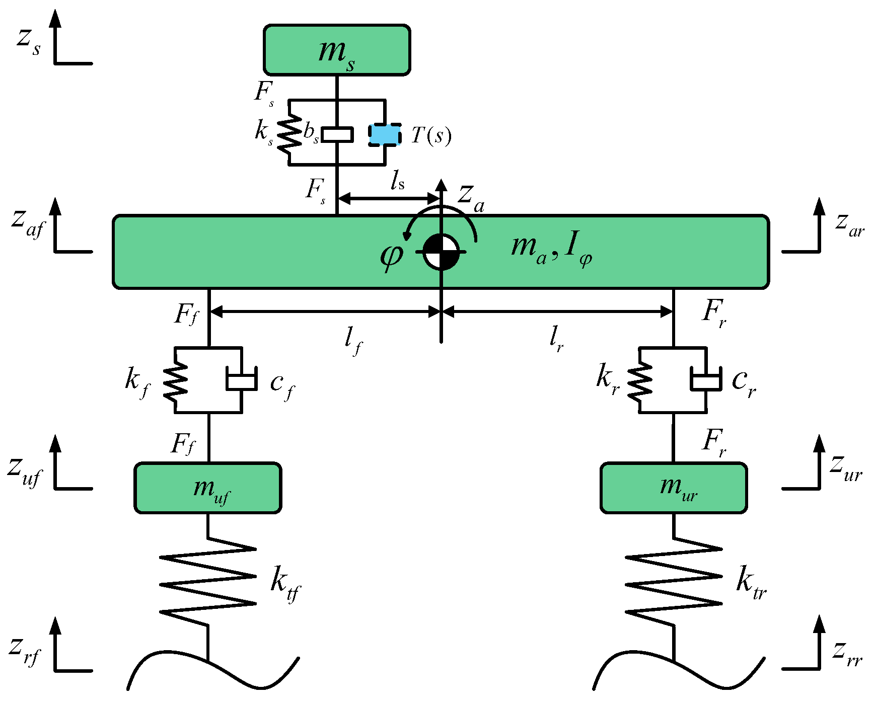
2. Half Vehicle Model

We refer to the half vehicle model built by Shen in 2021 [28]. Figure 1 shows the half vehicle model built for this study; this seven-degree-of-freedom model takes into account the vertical and pitch movements of the vehicle’s sprung mass and the vertical vibration of the seat. This study was carried out with the vehicle unloaded, therefore, the mass and inertia of the driver are not taken into account.
The vertical motion equation of the seat mass is
m s z ¨ s = F s
The equation representing the sprung mass vertical motion is
m a z ¨ a = k f ( z u f z a f ) + c f ( z ˙ u f z ˙ a f ) + k r ( z u r z a r ) + c r ( z ˙ u r z ˙ a r ) F s
The equation representing the sprung mass pitch motion is
I φ φ ¨ = l r F r + l s F s l f F f
The equations of the front and rear unsprung masses are
{ m u f z ¨ u f = k t f ( z r f z u f ) k f ( z u f z a f ) c f ( z ˙ u f z ˙ a f ) m u r z ¨ u r = k t r ( z r r z u r ) k r ( z u r z a r ) c r ( z ˙ u r z ˙ a r )
The pitch angle can be approximately equal to the following equation when the angle is relatively small.
{ z a s = z a l s φ z s f = z a l f φ z s r = z a + l r φ
where ms is the vehicle seat mass, zs is the seat’s vertical displacement, ma is the vehicle’s sprung mass, za is the vertical displacement of the body centroid, Fs is the seat’s suspension force, Ff and Fr are the forces of the front and rear suspensions, ls is the horizontal distance from the seat to the centroid, lf and lr are the distances from the front and rear axles to the body centroid, φ is the body pitch angle, Iφ is the body pitch moment of inertia, kf and cf are the spring’s stiffness and the damping coefficient of the front suspension, kr and cr are the spring’s stiffness and the damping coefficient of the rear suspension, muf and mur are the front and rear unsprung mass, zuf and zur are the vertical displacements of the front and rear unsprung mass, ktf and ktr are the equivalent stiffness of the front and rear tires, zrf and zrr are the displacement inputs of the front and rear wheels, zaf and zar are the vertical displacements of the front corner and rear corner of the vehicle’s body. This study was carried out on the basis of a passenger car model in order to achieve an effective increase in ride comfort in passenger cars; the model for this study was built on a mature, commercially available model. Table 1 shows the parameters of the half vehicle model.

3. Seat Suspension Layout

3.1. The Ball-Screw Mechatronic Inerter

The inerter is a mass element at both ends, and its output force is proportional to the relative acceleration at both ends. Inerters are available in ball-screw, rack and pinion, and fluid types. In this study, we have designed a ball-screw mechatronic inerter. The ball-screw mechatronic inerter comprises a rotary motor device and a ball-screw inerter. Among them, the ball-screw converts the linear reciprocating motion into a rotary motion and transmits it to the rotary motor. Figure 2 shows the working principle of the ball-screw mechatronic inerter.
According to Figure 2, the inertance of the ball-screw mechatronic inerter can be changed by modifying the rotational inertia of the flywheel mounted on the ball-screw shaft. When both endpoints of the ball-screw mechatronic inerter move in a straight line, the rotating motor rotor is driven by the ball-screw shaft, producing a voltage U that flows through the external electrical load. Re and Le are the coil resistance and inductance. In this paper, the coil factor is not considered in the optimization. The external electrical load can be adopted to simulate the corresponding mechanical network in the optimization process.

3.2. The Seat Suspension Layout

The designed seat suspension, using the mechatronic inerter, includes a mechanical part and an electrical network part. For the mechanical section, we needed to provide load-bearing capacity for the seat suspension by means of a parallel spring, which includes a spring and an inerter, and provides a fundamental seat suspension layout to protect the system in the event of electrical network failure. The electrical section involves resistors, inductors, and capacitors to simulate the dampers, springs, and inerters. Figure 3 shows the layout of the mechatronic seat suspension, where the mechatronic inerter is connected, in parallel, with the spring.
Where ks and bs are mechanical structures and T(s) is the impedance expression to be solved; the double primary impedance transfer function is as follows:
T ( s ) = α 1 s + α 0 β 1 s + β 0
where α i 0 , β i 0 ( β i are not all 0). The positive real constraints of the double primary impedance transfer function are as follows:
α 1 β 1 0
The biquadratic impedance transfer function is as follows:
T ( s ) = α 2 s 2 + α 1 s + α 0 β 2 s 2 + β 1 s + β 0
where α i 0 , β i 0 ( β i are not all 0). The positive realness constraints of the biquadratic impedance transfer function are as follows:
( α 2 β 0 α 0 β 2 ) 2 α 1 β 1
The bicubic impedance transfer function is as follows:
T ( s ) = α 3 s 3 + α 2 s 2 + α 1 s + α 0 β 3 s 3 + β 2 s 2 + β 3 s + β 0
where α i 0 , β i 0 ( β i are not all 0). The positive realness constraints of the bicubic impedance transfer function are as follows:
{ ( α 1 + β 1 ) ( α 2 + β 2 ) ( α 0 + β 0 ) ( α 3 + β 3 ) ; a 3 = 0 , a 2 0 , a 0 0 , a 1 2 a 0 a 2 ; a 3 > 0 , a 0 0 , a 1 0 , a 2 3 a 1 a 3 o r a 2 2 > 3 a 1 a 3 , 2 a 2 3 9 a 1 a 2 a 3 + 27 a 0 a 3 2 2 ( a 2 2 3 a 1 a 3 ) 3 / 2
where a 0 = α 0 β 0 , a 1 = α 1 β 1 α 0 β 2 α 2 β 0 , a 2 = α 2 β 2 α 1 β 3 α 3 β 1 , a 3 = α 3 β 3 .

4. Optimal Design of the Mechatronic Seat Suspension

For optimum performance of the mechatronic seat suspension, the parameters of the designed seat suspension systems are optimized via particle swarm optimization. To begin with, the particle is initialized, and the fit value of the particle is then compared with the best location it passes through, and the speed and position of the particle are updated. This ends when the termination condition is met. As the model for this study was built on a mature, commercially available model, before optimization, the main spring coefficient for protection remained the same as the conventional suspension, and only the parameters in T(s) and b were optimized to give the optimization results practical significance.
Assuming the vehicle is driving at 30 km/h on a C grade road [29], and taking into account the vertical acceleration of the seat and the acceleration of the pitch motion; then, the objective function is defined as
f = J 1 J 1 pas + J 2 J 2 pas
where J1pas and J2pas are the root-mean-square (RMS) values of the seat vertical acceleration and the pitch motion acceleration of traditional passive suspension. Here, J1pas = 0.9913 m/s2 and J2pas = 1.2852 rad/s2. J1 and J2 are the RMS values of the seat vertical acceleration and the pitch motion acceleration of the designed suspension system. The mechanical inertance b and the T(s) transfer function as the optimization variables. Particle swarm optimization was used to find the global optimum by following the current search. This algorithm has attracted academic attention for its ease of implementation, high accuracy and fast convergence. Equations (13) and (14) are the updated formulas for the particle velocity and position properties.
V n + 1 = λ V n + d 1 r 1 ( P i d n X n ) + d 2 r 2 ( P g d n X n )
X n + 1 = X n + V n + 1
where λ is the inertia factor, V is the velocity of the particle, X is the particle’s position, n is the iterations number, and d1 and d2 are non-negative constants. The random numbers r1 and r2 usually have a value between 0 and 1, while Pid and Pgd are the individual extremum and global extremum. Figure 4 shows the optimization process of the algorithm.
The optimized results of the transfer functions can be passively realized by the electrical network involving resistors, capacitors, and inductors. Figure 5 illustrates the corresponding network; Table 2 shows the detailed parameters.

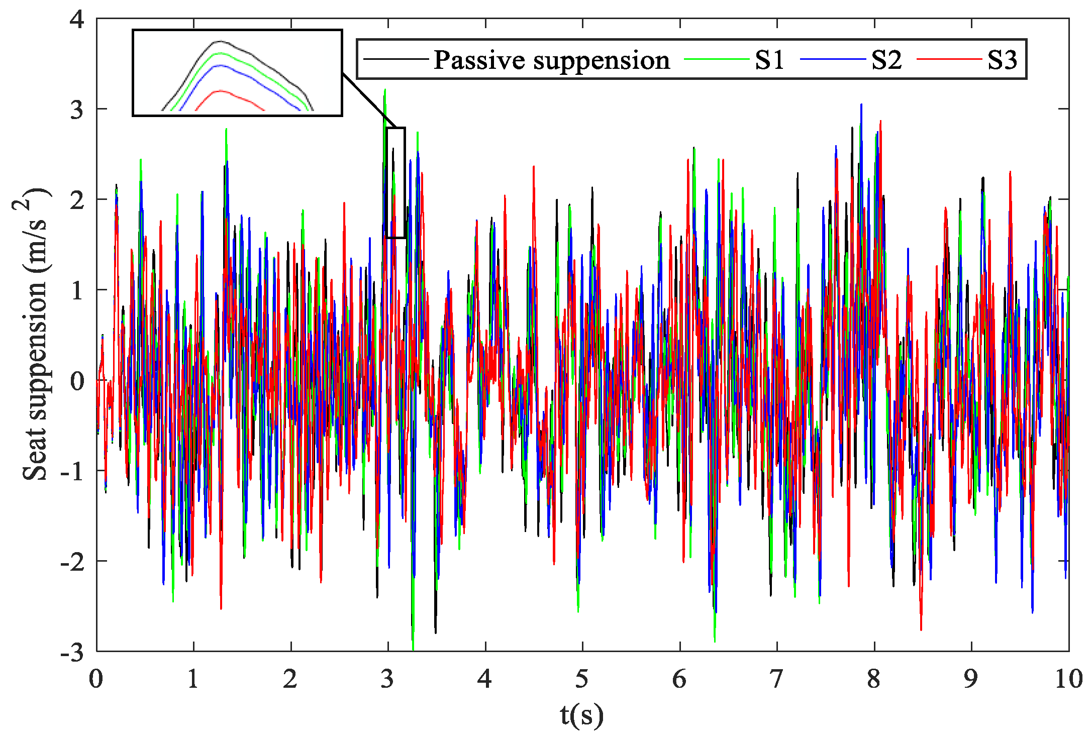
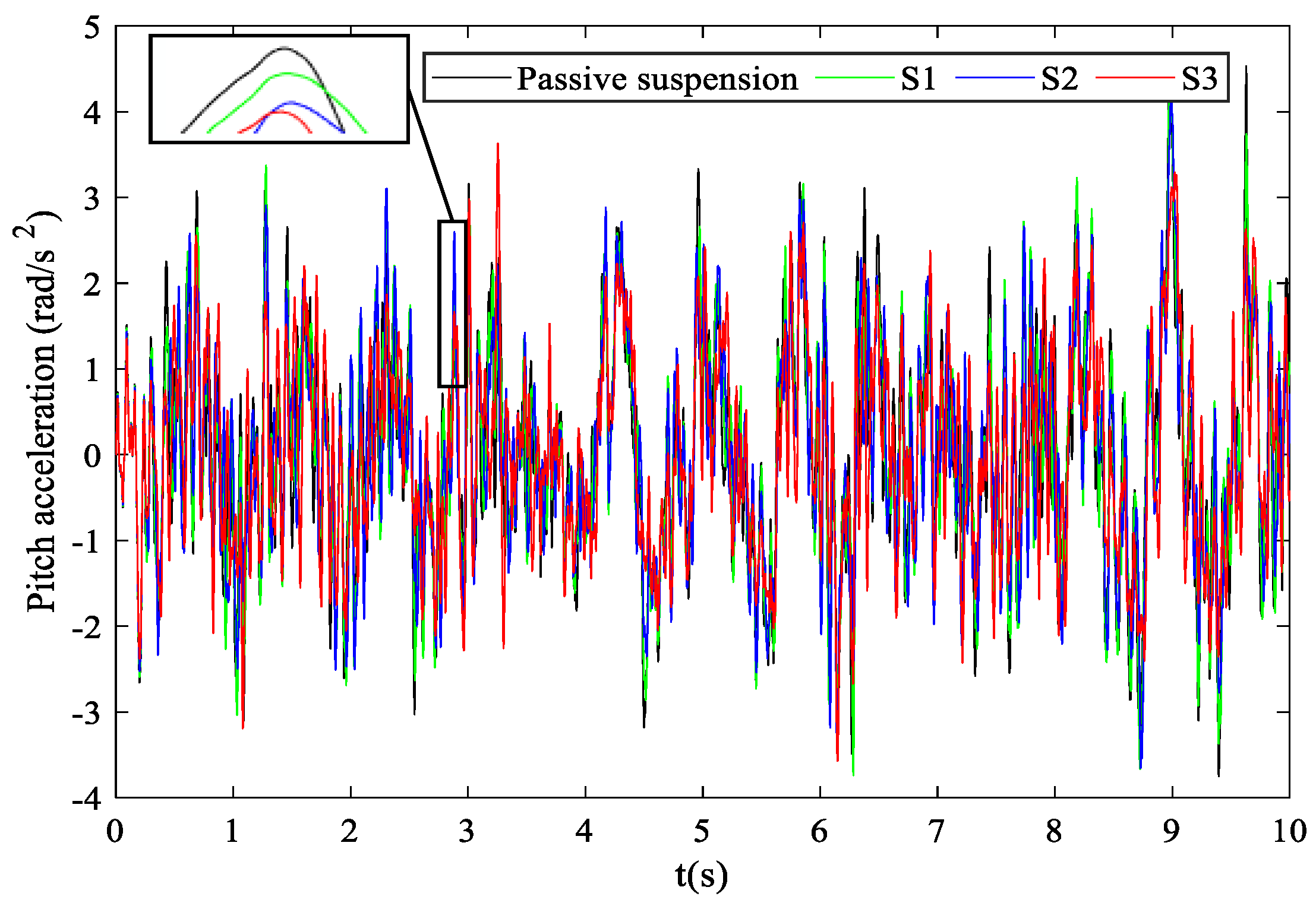
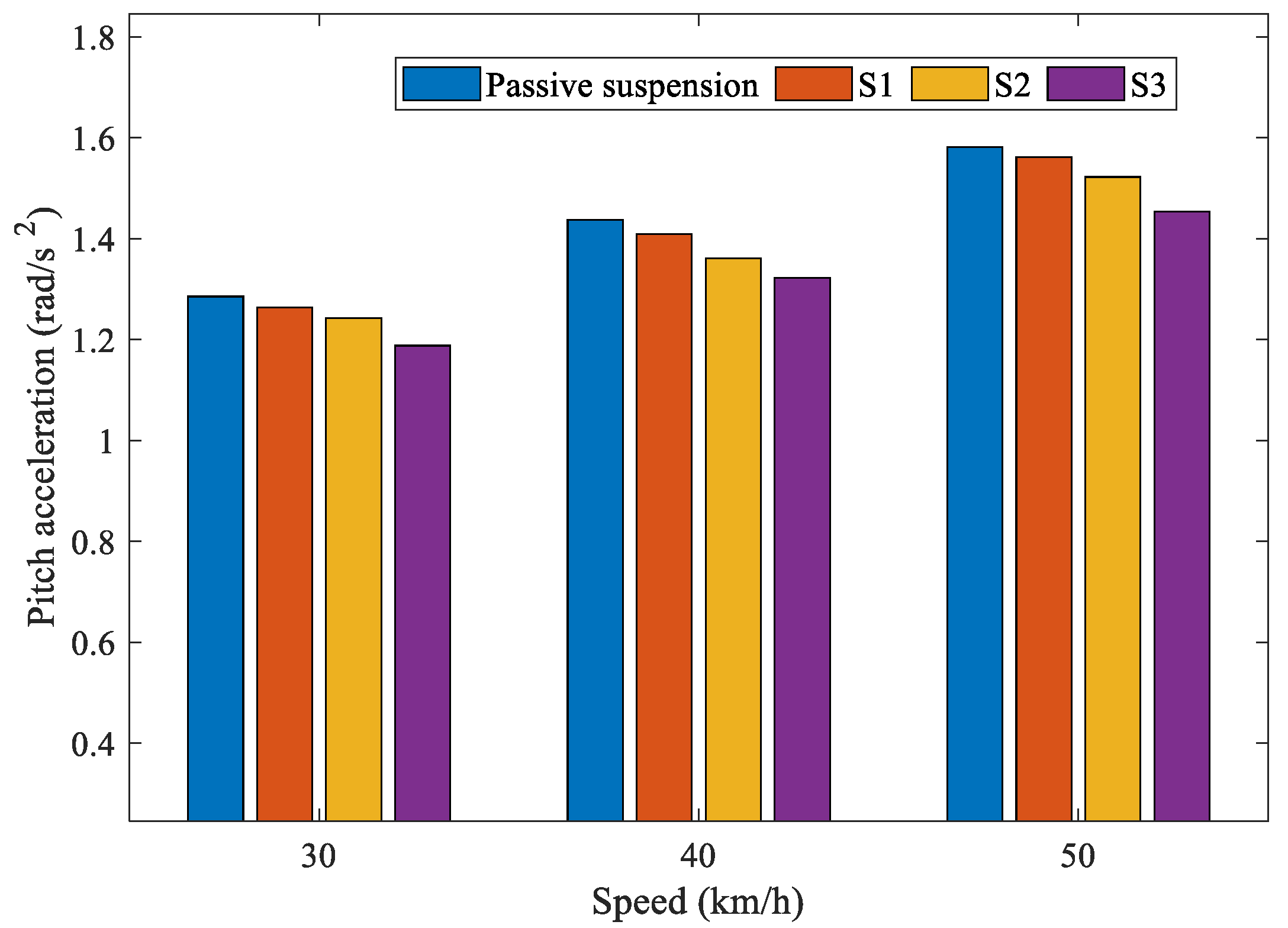
5. Performance Evaluation

The structural optimization of the designed seat suspension was required for the application of the mechatronic inerter. Table 3 shows the RMS values of the seat acceleration and pitch acceleration among the different suspension systems at a speed of 30 km/h.
Table 3 shows that, for the S1 seat suspension layout, the RMS values of the seat acceleration and the pitch acceleration decreased by 2.51% and 1.67%, respectively. The improvements are not obvious. Therefore, as the transfer function of the external electrical network increases in order, the RMS values of the seat acceleration and the pitch acceleration of the S2 seat suspension layout are further reduced by 4.58% and 3.41%, respectively. Then, for the S3 seat suspension layout, which used a bicubic transfer function electrical network, the RMS values of the seat acceleration and the pitch acceleration decreased by 10.56% and 7.57%, respectively; this resulted in a significant improvement in the ride comfort of the vehicle seat suspension. A comparison of the time domain characteristics of the seat acceleration and the pitch acceleration are shown in Figure 6 and Figure 7. Figure 8 and Figure 9 show the comparisons of the RMS values of the seat acceleration and the pitch acceleration at different speeds.
It is noted that, as the vehicle speed increases, the RMS values of the seat acceleration under the same suspension structure also increase. Under the same vehicle speed, the higher the transfer function order is, the smaller the RMS values of the seat acceleration are. For the pitch acceleration, as can be seen in the bar chart, when the speed of the vehicle increased, the pitch acceleration under the same type of suspension also increased. As the order of transfer function of the external electrical network increased, the pitch acceleration was reduced. In conclusion, the RMS values of the seat acceleration and pitch acceleration of the S3 layout are significantly lower than those of the S1 and S2 layouts, and passive suspension.

6. Conclusions

In this study, a mechatronic inerter element was introduced into the structural design of vehicle seat suspensions, and the problem of optimizing the design of the vehicle seat suspension, to integrate the mechatronic inerter element, was investigated. In addition, the vertical and pitch movements of the vehicle’s sprung mass and the vertical vibration of the seat were considered in a half vehicle model. Based on a ball-screw mechatronic inerter, the external electrical networks, using different transfer function-orders, were optimized via the particle swarm optimization algorithm. The results show that, as the external electrical network transfer function-order is increased, the RMS values of the seat acceleration and pitch acceleration will be further reduced. The RMS values of the seat acceleration and pitch acceleration can be simultaneously reduced by 10.56% and 7.57%, respectively, at most. The performance of vehicle seat suspensions with an integrated mechatronic inerter element can be improved by increasing the order of the external electrical network transfer function.

Author Contributions

Conceptualization, C.Q.; methodology, Y.S.; software, X.L.; validation, X.L.; formal analysis, C.Q.; investigation, Y.S.; writing—original draft preparation, C.Q.; writing—review and editing, Y.S.; supervision, X.L. All authors have read and agreed to the published version of the manuscript.

Funding

This work was supported by the Natural Science Foundation of Beijing Municipality (No. 3214045), and the Natural Science Foundation of Jiangsu Province (No. BK20211364).

Data Availability Statement

The data used to support the findings of the study are available from the corresponding author upon request.

Conflicts of Interest

The authors declare no conflict of interest.

References

  1. Choi, S.; Choi, Y.T.; Chang, E.G.; Han, S.J.; Kim, C.S. Control characteristics of a continuously variable ER damper. Mechatronics 1998, 8, 143–161. [Google Scholar] [CrossRef]
  2. Rakheja, S.; Afework, Y.; Sankar, S. An analytical and experimental investigation of the driver-seat-suspension system. Veh. Syst. Dyn. 1994, 23, 501–524. [Google Scholar] [CrossRef]
  3. Tong, R.T.; Amirouche, F. Ride control-a two state suspension design for cabs and seats. Veh. Syst. Dyn. 1999, 33, 578–589. [Google Scholar] [CrossRef]
  4. Wereley, N.M.; Pang, L. Nondimensional analysis of semi-active electrorheological and magnetorheological dampers using approximate parallel plate models. Smart Mater. Struct. 1997, 7, 732–743. [Google Scholar] [CrossRef]
  5. Amirouche, F.; Palkovics, L.; Woodrooffe, J. Optimal driver seat suspension design for heavy trucks. Transp. Syst. ASME 1994, 2, 277–291. [Google Scholar]
  6. Andersson, R. The low back pain of bus drivers in an urban area of California. Spine 1982, 17, 1481–1488. [Google Scholar] [CrossRef]
  7. Deng, H.; Deng, J.; Yue, R.; Han, G.; Zhang, J.; Ma, M.; Zhong, X. Design and verification of a seat suspension with variable stiffness and damping. Smart Mater. Struct. 2019, 28, 65015. [Google Scholar] [CrossRef]
  8. Ning, D.; Du, H.; Sun, S.; Li, W.; Zhang, N.; Dong, M. A novel electrical variable stiffness device for vehicle seat suspension control with mismatched disturbance compensation. IEEE ASME Trans. Mechatron. 2019, 24, 2019–2030. [Google Scholar] [CrossRef]
  9. Liao, X.; Du, X.; Li, S. Design of cab seat suspension system for construction machinery based on negative stiffness structure. Adv. Mech. Eng. 2021, 13, 1–15. [Google Scholar] [CrossRef]
  10. Liu, P.; Ning, D.; Luo, L.; Zhang, N.; Du, H. An electromagnetic variable inertance and damping seat suspension with controllable circuits. IEEE Trans. Ind. Electron. 2021, 69, 2811–2821. [Google Scholar] [CrossRef]
  11. Smith, M.C.; Wang, F. Performance benefits in passive vehicle suspensions employing inerters. Veh. Syst. Dyn. 2004, 42, 235–257. [Google Scholar] [CrossRef]
  12. Zhang, C.; Zhang, Z.; Zhao, H. Analysis of dynamic characteristics and ride performance of automobile active suspension. Chin. Agric. Mech. 2015, 36, 176–179. [Google Scholar] [CrossRef]
  13. Huang, C.; Chen, L.; Yuan, Z.; Jiang, H.; Niu, L. Hybrid fuzzy control of semi-active suspension system. Automot. Eng. 2014, 36, 999–1018. [Google Scholar]
  14. Smith Malcolm, C. Synthesis of mechanical networks: The inerter. IEEE Trans. Autom. Control 2002, 47, 1648–1662. [Google Scholar] [CrossRef] [Green Version]
  15. Zhao, Z.-P.; Chen, Q.-J.; Zhang, R.-F.; Pan, P.; Jian, Y.-Y. Energy dissipation mechanism of inerter systems. Int. J. Mech. Sci. 2020, 184, 105845. [Google Scholar] [CrossRef]
  16. Chen, M.Z.Q.; Hu, Y.L.; Li, C.Y.; Chen, G. Application of semi-active inerter in semi-active suspensions via force tracking. J. Vib. Acoust. 2016, 138, 041014. [Google Scholar] [CrossRef]
  17. Hu, Y.L.; Wang, K.; Chen, Y.H.; Chen, M.Z.Q. Inerter-based semi-active suspensions with low-order mechanical admittance via network synthesis. Trans. Inst. Meas. Control 2018, 40, 4233–4245. [Google Scholar] [CrossRef]
  18. Liu, Y.L.; Zhao, W.T.; Yang, X.F.; Shen, Y.J. Predictive control of vehicle ISD suspension based on a hydraulic electric inerter. Shock Vib. 2019, 2019, 9230736. [Google Scholar] [CrossRef] [Green Version]
  19. Zhang, S.Y.; Jiang, J.Z.; Neild, S.A. Optimal configurations for a linear vibration suppression device in a multi-storey building. Struct. Control Health Monit. 2016, 24, e1887. [Google Scholar] [CrossRef] [Green Version]
  20. Giaralis, A.; Petrini, F. Wind-induced vibration mitigation in tall buildings using the tuned mass-damper-inerter. J. Struct. Eng. 2017, 142, 04017127. [Google Scholar] [CrossRef]
  21. Yang, L.; Wang, R.; Ding, R.; Liu, W.; Zhu, Z. Investigation on the dynamic performance of a new semi-active hydro-pneumatic inerter-based suspension system with MPC control strategy. Mech. Syst. Signal Process. 2021, 154, 107569. [Google Scholar] [CrossRef]
  22. Shen, Y.; Hua, J.; Fan, W.; Liu, Y.; Yang, X.; Chen, L. Optimal design and dynamic performance analysis of a fractional-order electrical network-based vehicle mechatronic ISD suspension. Mech. Syst. Signal Process. 2023, 184, 109718. [Google Scholar] [CrossRef]
  23. Li, Y.; Yang, X.; Shen, Y.; Liu, Y.; Wang, W. Optimal design and dynamic control of the HMDV inertial suspension based on the ground-hook positive real network. Adv. Eng. Softw. 2022, 171, 103171. [Google Scholar] [CrossRef]
  24. Shen, Y.; Chen, L.; Liu, Y.; Zhang, X. Influence of fluid inerter nonlinearities on vehicle suspension performance. Adv. Mech. Eng. 2017, 9, 1687814017737257. [Google Scholar] [CrossRef]
  25. Sun, X.Q.; Chen, L.; Wang, S.H.; Zhang, X.L.; Yang, X.F. Performance investigation of vehicle suspension system with nonlinear ball-screw inerter. Int. J. Automot. Technol. 2016, 17, 399–408. [Google Scholar] [CrossRef]
  26. Liu, C.; Chen, L.; Zhang, X.; Yang, Y.; Nie, J. Design and tests of a controllable inerter with fluid-air mixture condition. IEEE Access 2020, 8, 125620–125629. [Google Scholar] [CrossRef]
  27. Yang, X.; He, T.; Shen, Y.; Liu, Y.; Yan, L. Research on predictive coordinated control of ride comfort and road friendliness for heavy vehicle ISD suspension based on the hybrid-hook damping strategy. Proc. Inst. Mech. Eng. D J. Automob. Eng. 2022. [Google Scholar] [CrossRef]
  28. Shen, Y.; Hua, J.; Wu, B.; Chen, Z.; Xiong, X.; Chen, L. Optimal design of the vehicle mechatronic ISD suspension system using the structure-immittance approach. Proc. Inst. Mech. Eng. D J. Automob. Eng. 2022, 236, 512–521. [Google Scholar] [CrossRef]
  29. ISO 8608:2016; Mechanical Vibration—Road Surface Profiles—Reporting of Measured Data. International Organization for Standardization: Geneva, Switzerland, 2016. Available online: https://www.iso.org/standard/71202.html. (accessed on 22 November 2022).
Figure 1. Seven-degree-of-freedom vehicle model.
Wevj 14 00029 g001
Figure 2. Ball-screw mechatronic inerter.
Wevj 14 00029 g002
Figure 3. General layout of the seat suspension.
Wevj 14 00029 g003
Figure 4. The optimization process of particle swarm optimization.
Wevj 14 00029 g004
Figure 5. Electrical network. (a) Bivariate transfer function electrical network; (b) Biquadratic transfer function electrical network; (c) Bicubic transfer function electrical network.
Wevj 14 00029 g005
Figure 6. Comparison of the seat accelerations in the time domain.
Wevj 14 00029 g006
Figure 7. Comparison of the pitch accelerations in the time domain.
Wevj 14 00029 g007
Figure 8. Comparison of the RMS of seat acceleration under different speeds.
Wevj 14 00029 g008
Figure 9. Comparison of the RMS of pitch acceleration under different speeds.
Wevj 14 00029 g009
Table 1. Main parameters of the vehicle model.
NameValue
Seat mass ms (kg)48
Body centroid mass ma (kg)928.2
Unsprung mass of front wheels muf (kg)26.5
Unsprung mass of rear wheels mur (kg)24.4
Distance from seat to centroid ls (m)0.324
Distance from front axle to centroid lf (m)0.968
Distance from rear axle to centroid lr (m)1.392
Moment of inertia aound the Y axis Iφ (kg·m2)1058
Front suspension stiffness kf (kN·m−1)25
Rear suspension stiffness kr (kN·m−1)22
Front suspension damping cf (Ns/m)1500
Rear suspension damping cr (Ns/m)1300
Tire stiffness kt (kN·m−1)192
Table 2. Electrical network parameters.
NameValue
Resistor R11 (Ω)4877
Resistor R12 (Ω)654
Capacitor C11 (F)0.0047
Resistor R21 (Ω)98,754
Resistor R22 (Ω)35,789
Resistor R23 (Ω)5711
Capacitor C21 (F)0.0079
Inductor L21 (H)0.34
Resistor R31 (Ω)81
Resistor R32 (Ω)6998
Resistor R33 (Ω)74,223
Resistor R34 (Ω)158
Capacitor C31 (F)0.0024
Capacitor C32 (F)0.0017
Inductor L31 (H)0.76
Table 3. Comparison of the different seat suspension systems.
RMS of Seat AccelerationImprovementRMS of Pitch AccelerationImprovement
Passive suspension0.9913/1.2852/
Layout S10.96642.51%1.26381.67%
Layout S20.94594.58%1.24143.41%
Layout S30.886610.56%1.18797.57%
Disclaimer/Publisher’s Note: The statements, opinions and data contained in all publications are solely those of the individual author(s) and contributor(s) and not of MDPI and/or the editor(s). MDPI and/or the editor(s) disclaim responsibility for any injury to people or property resulting from any ideas, methods, instructions or products referred to in the content.

