

A Review of Position Sensorless Compound Control for PMSM Drives
Abstract
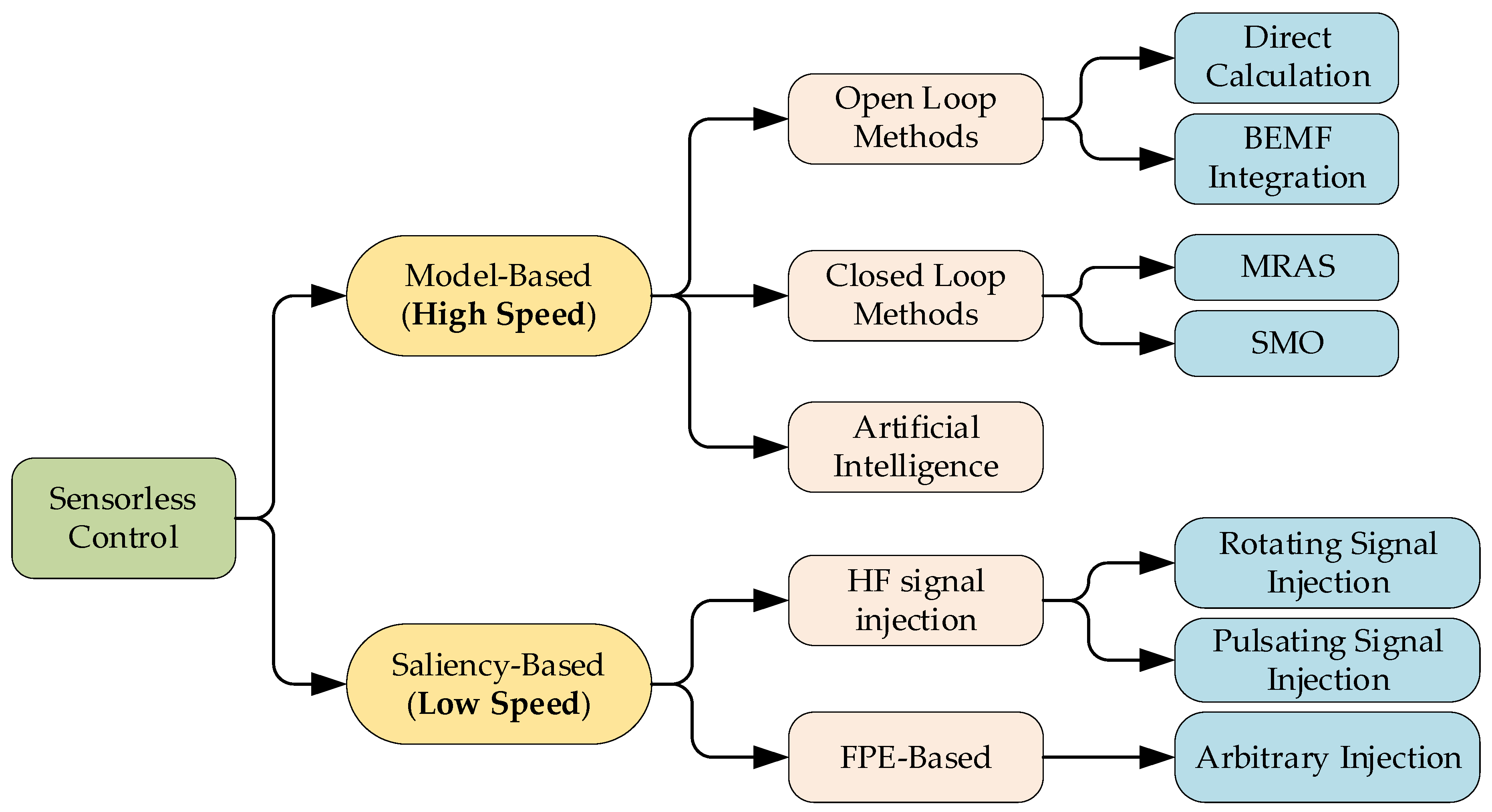
:1. Introduction
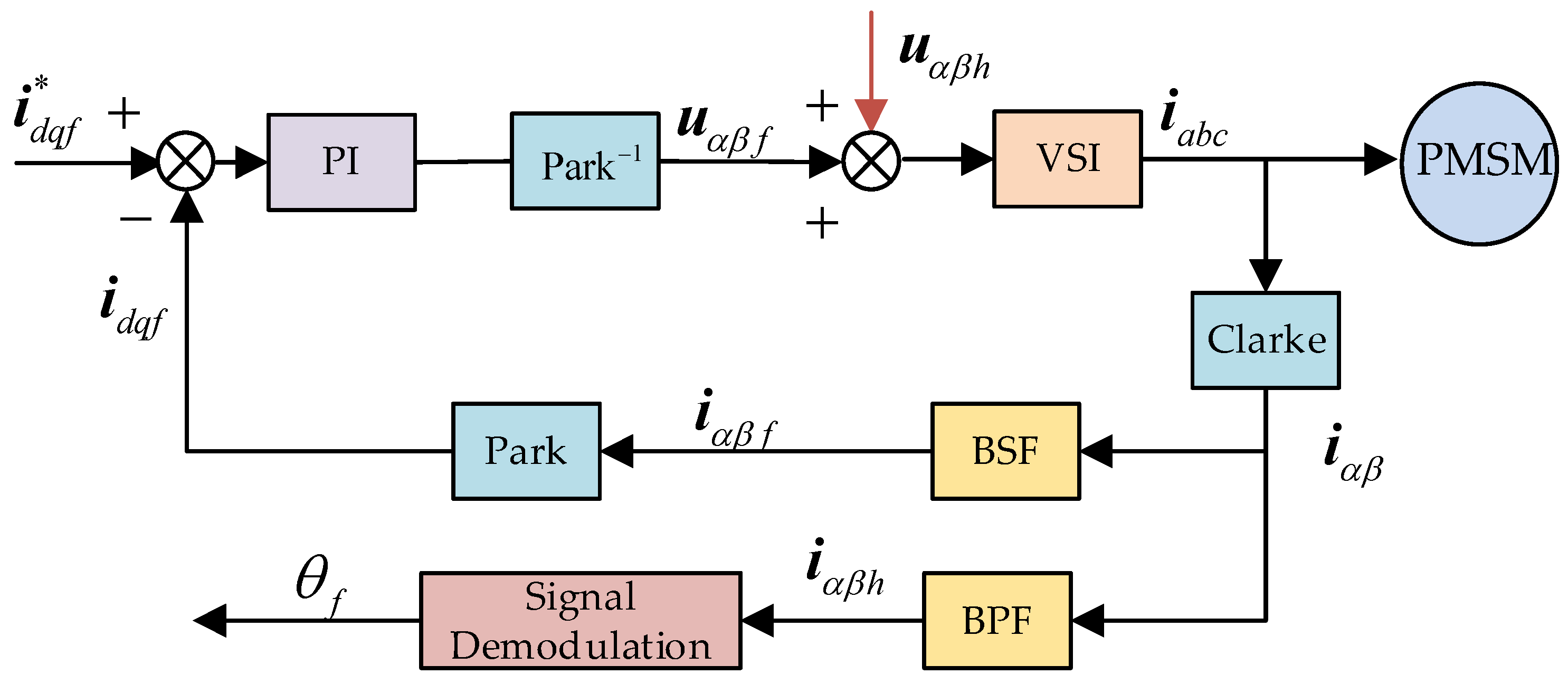
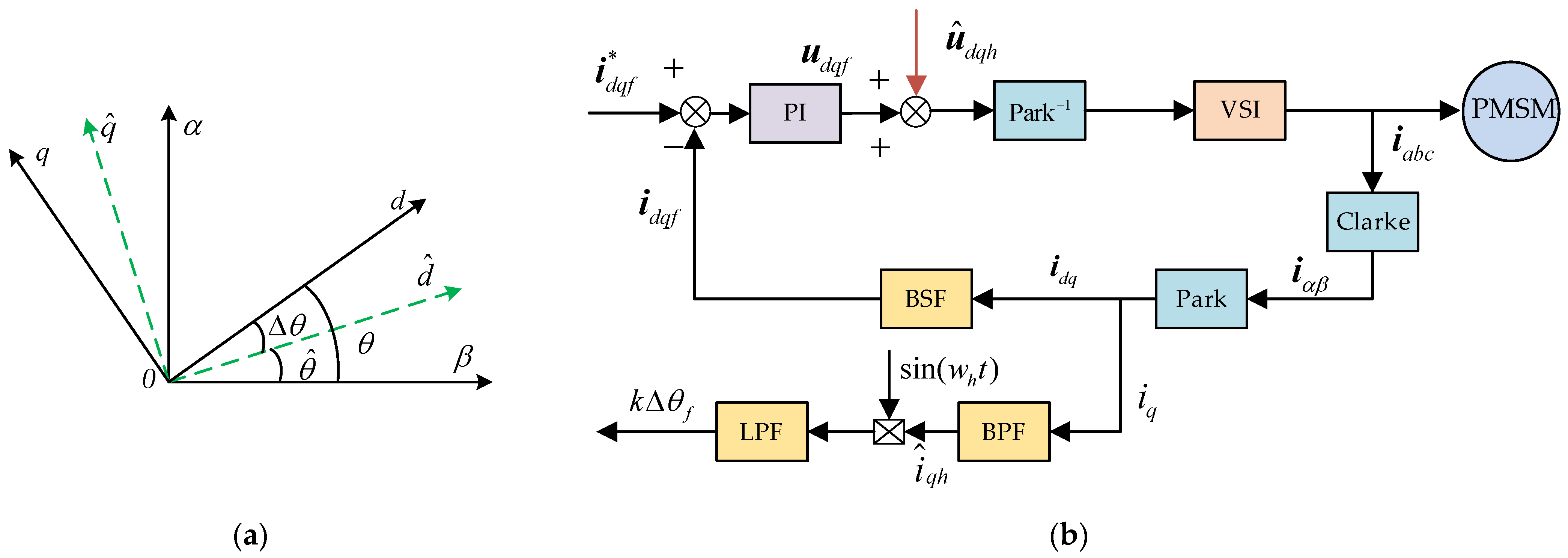
2. Compound Control Based on High-Frequency Injection Method
- High-frequency rotating injection method:
- 2.
- High-frequency pulsating injection method:
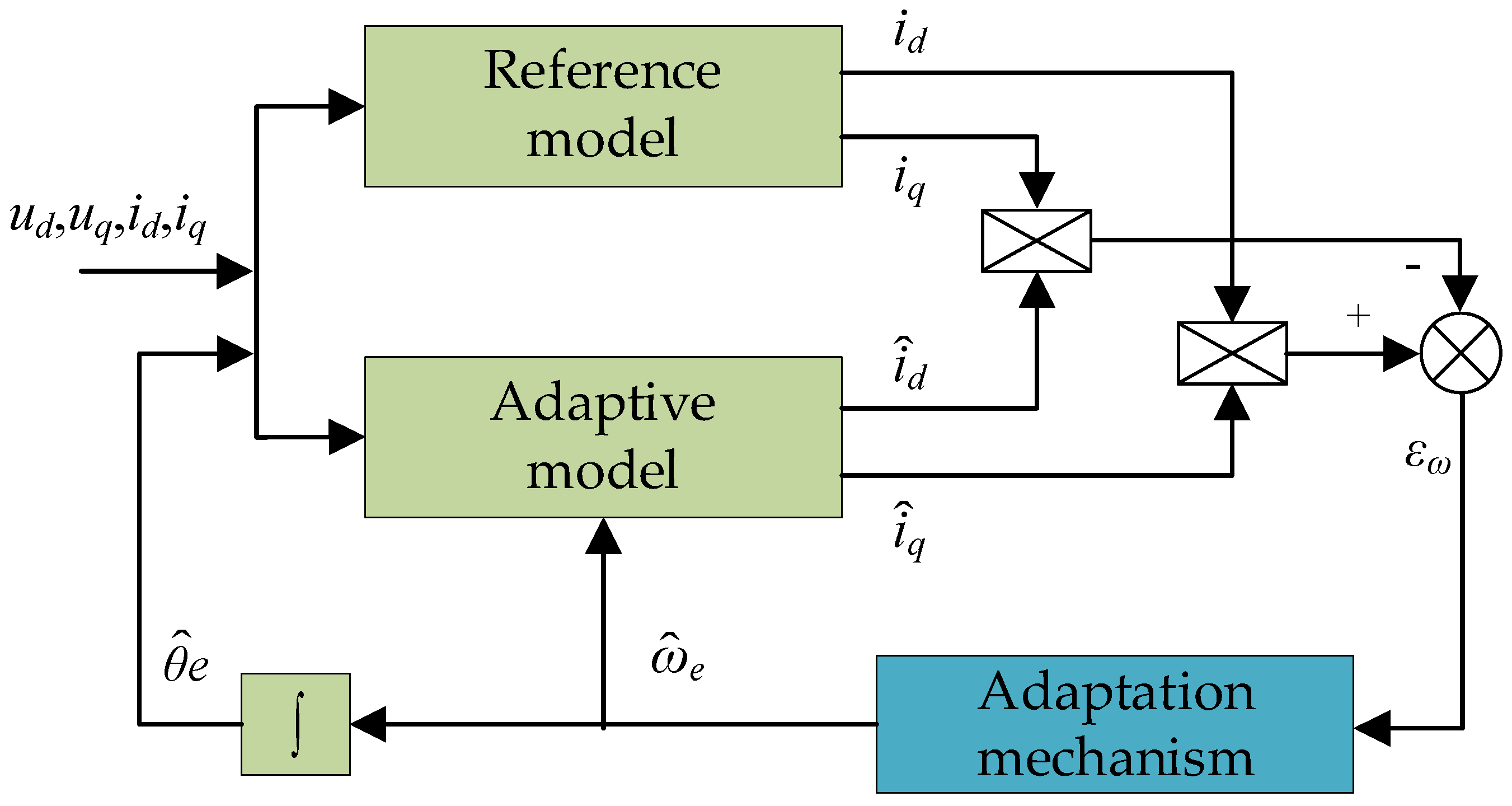
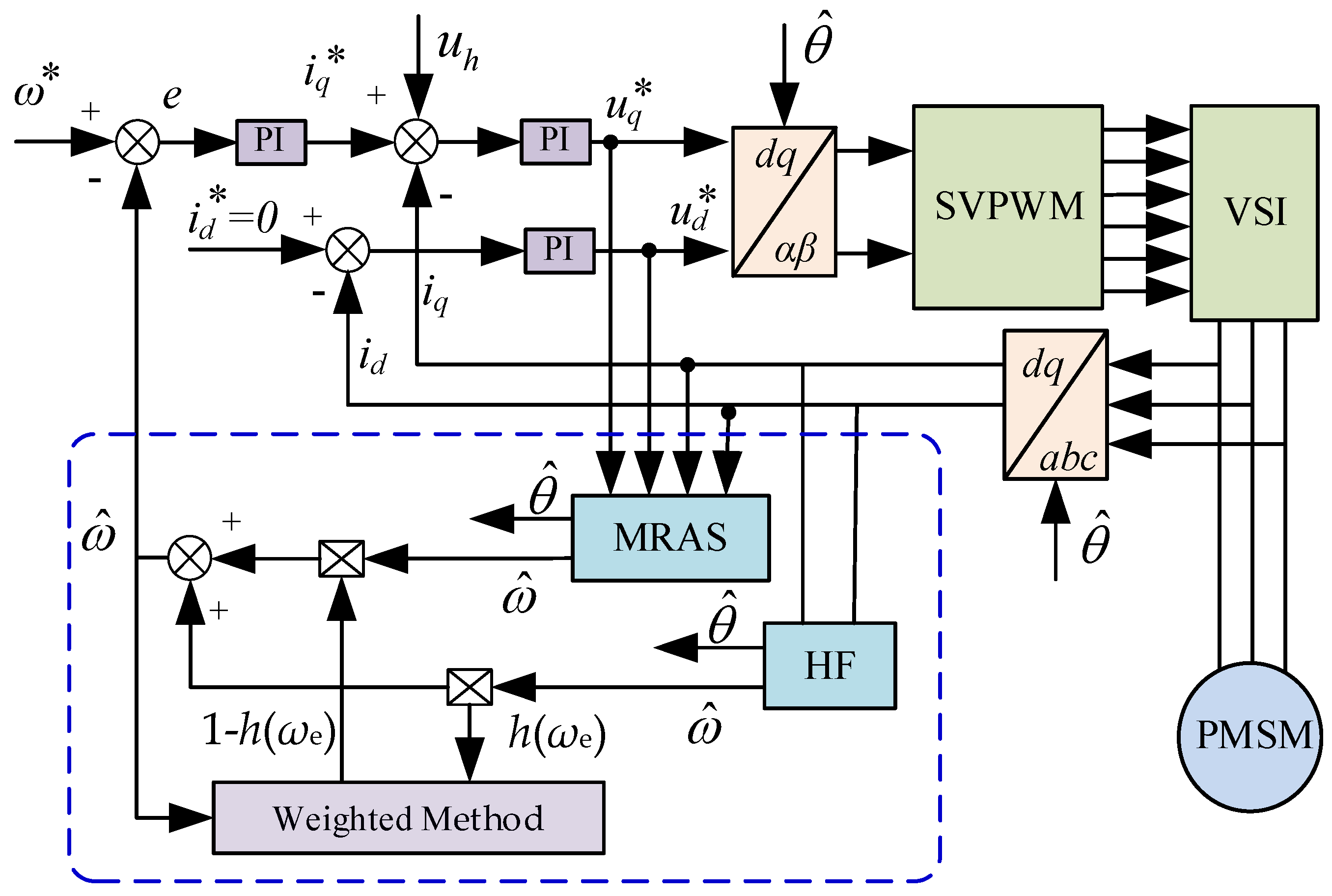
2.1. HF Compounded with Model Reference Adaptive Method
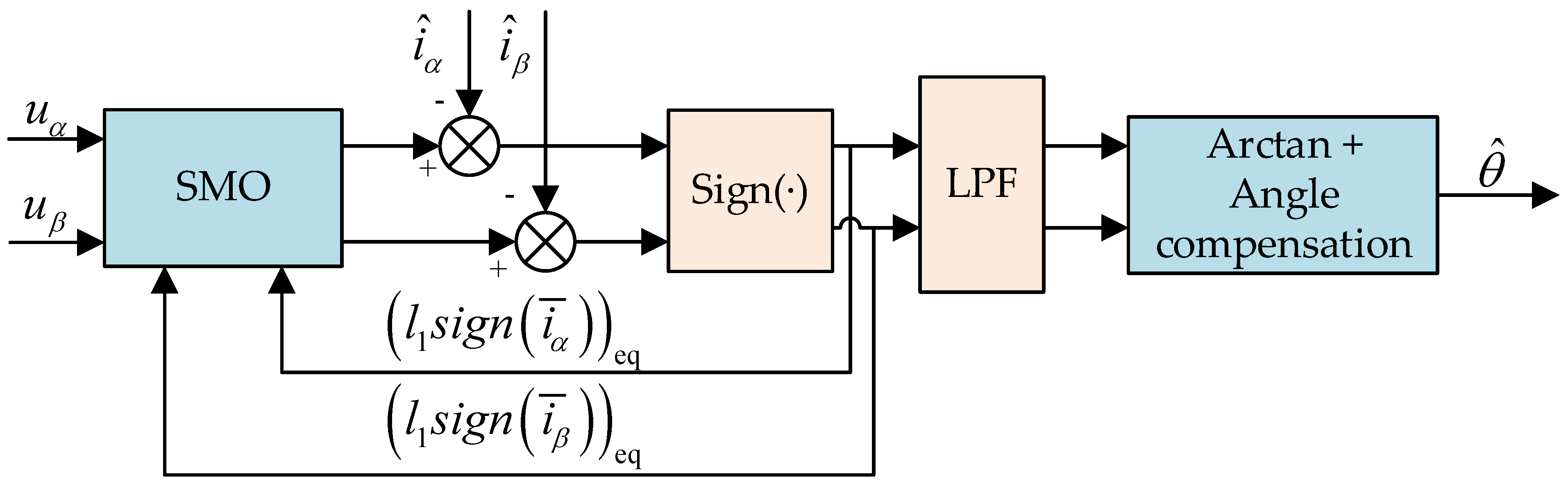
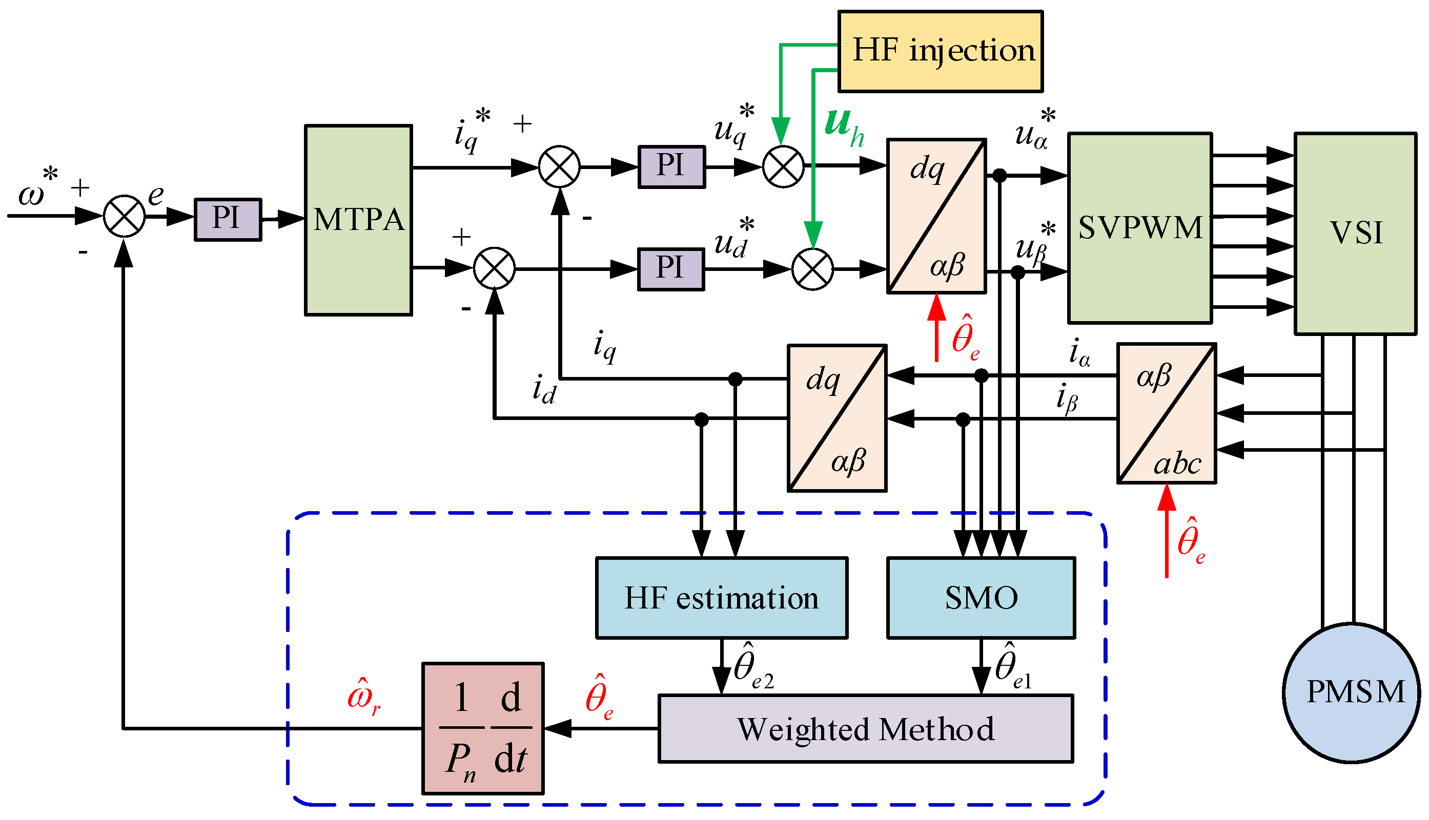
2.2. HF Compounded with Sliding Mode Observer
2.3. HF Compounded with BEMF Integration Method or Flux Estimation
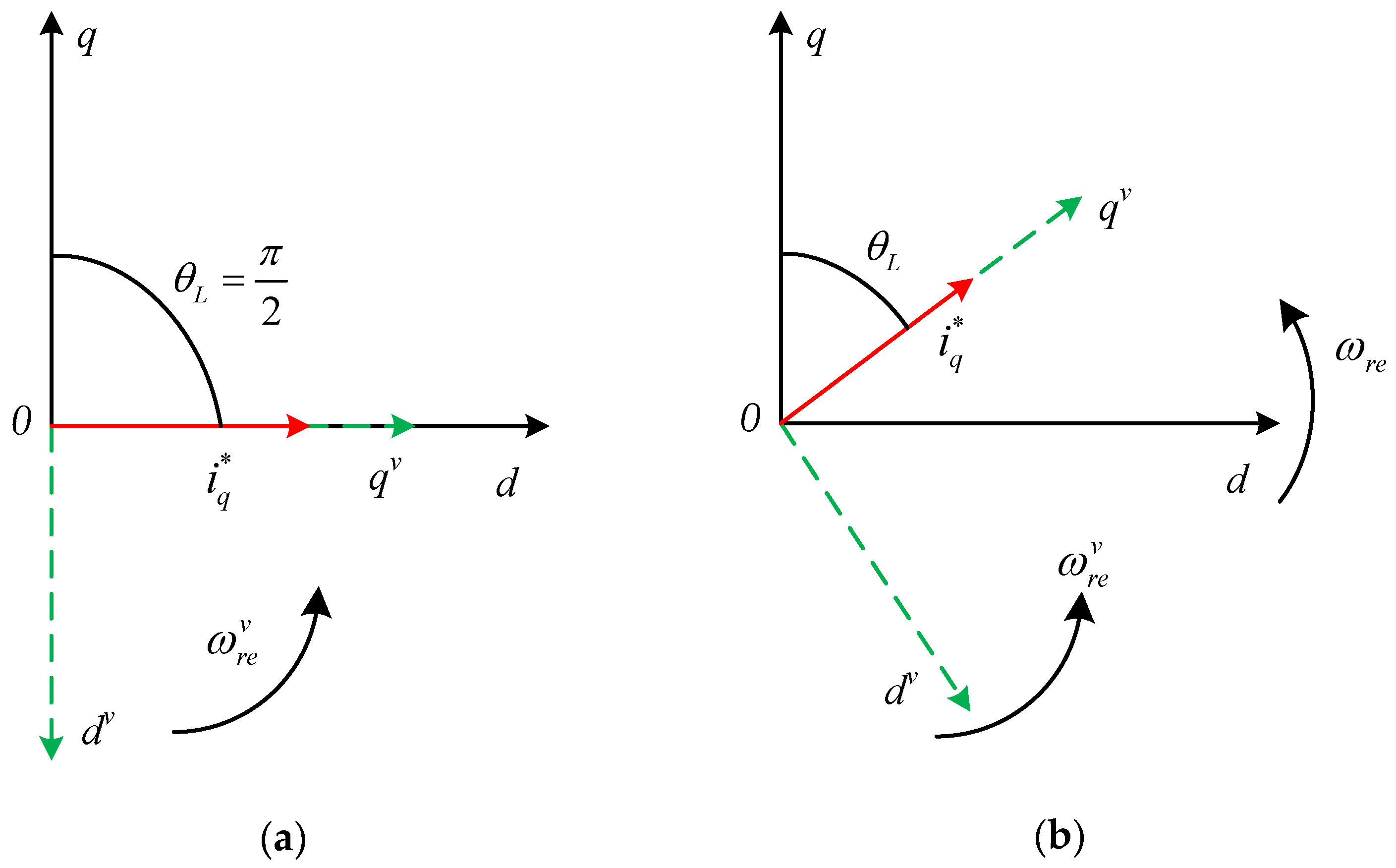
3. Compound Control Algorithm Based on I/F Control
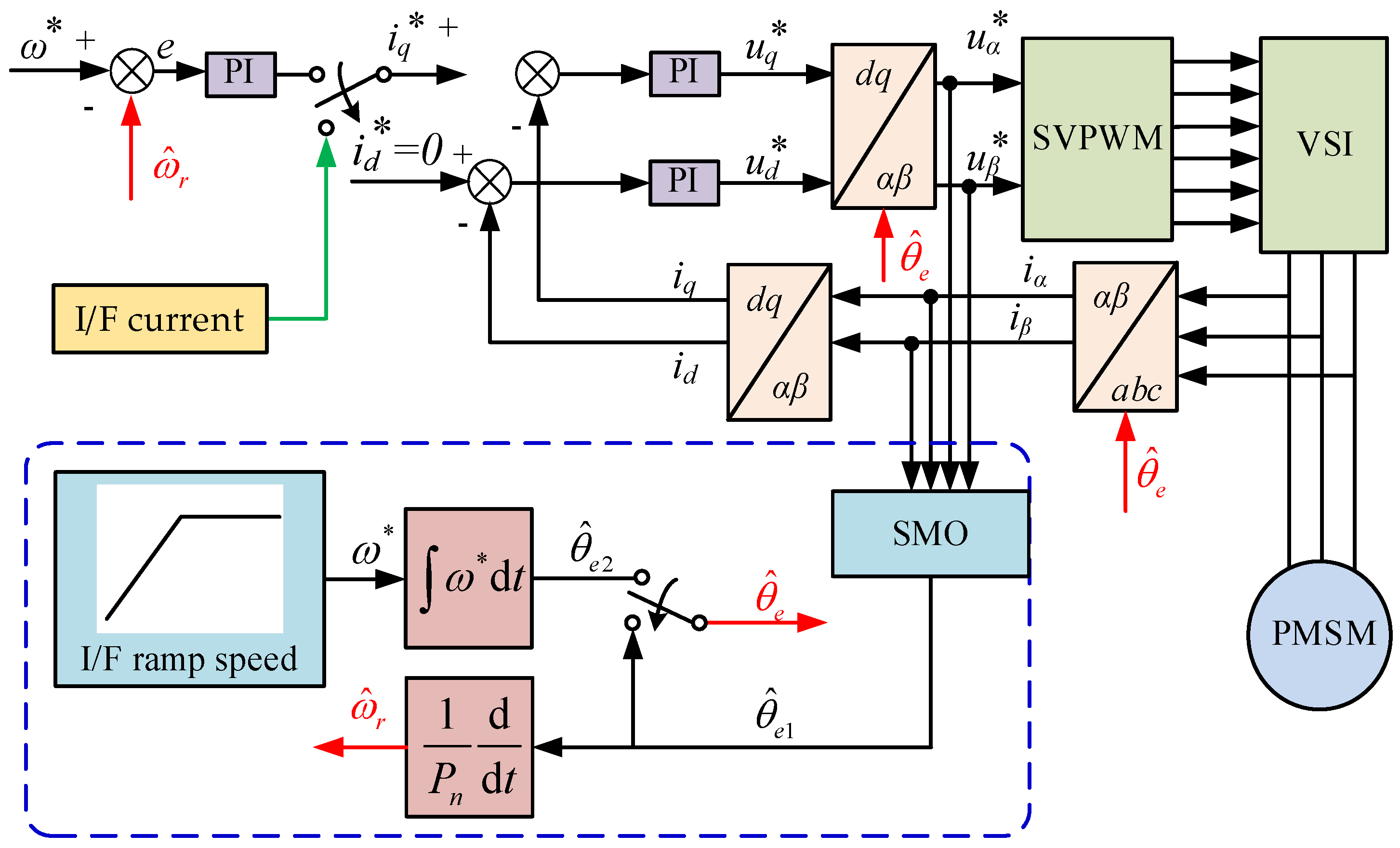
3.1. I/F Compounded with Sliding Mode Observer
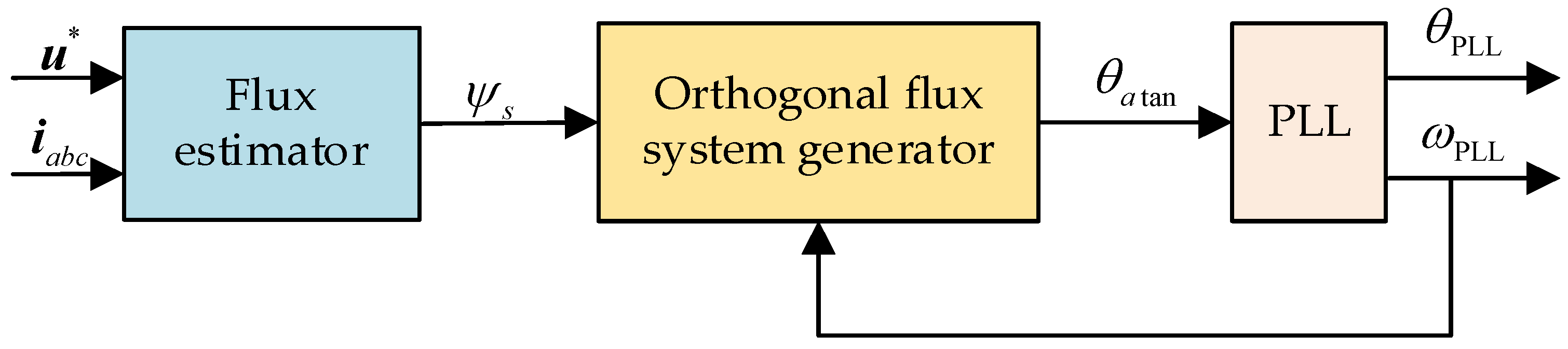
3.2. I/F Compounded with Flux Obsever
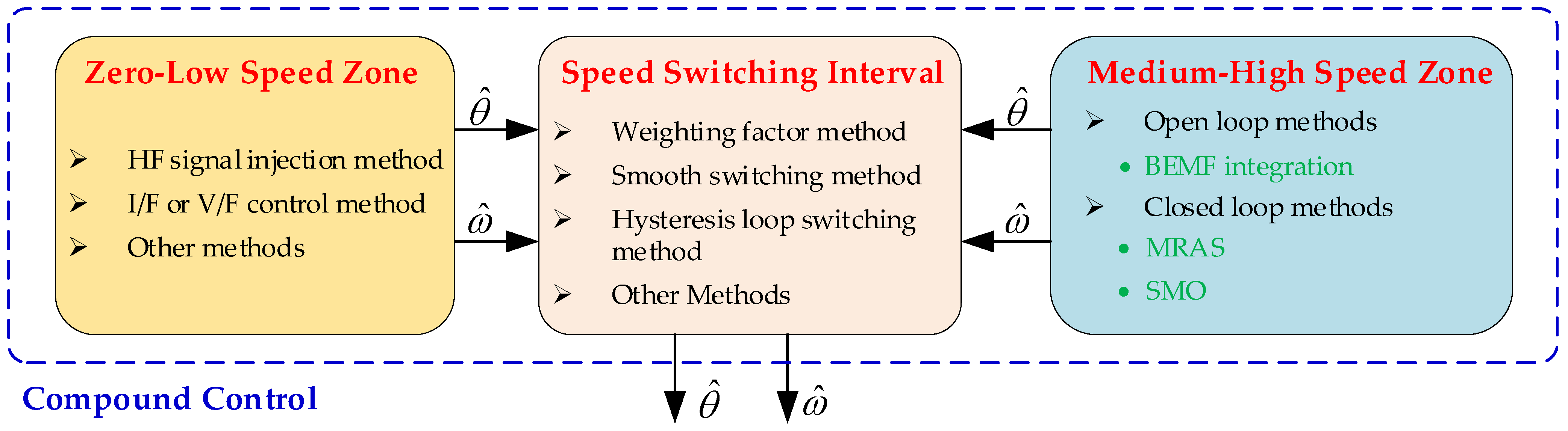
4. Switching Methods
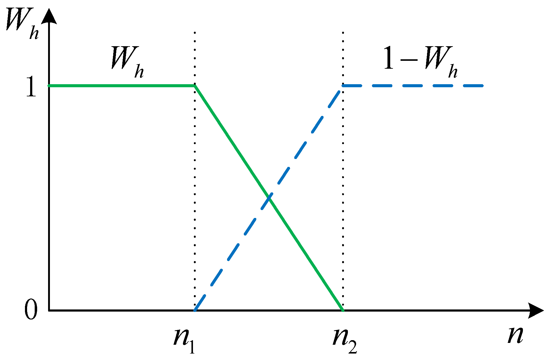
4.1. Weighting Factor Method
4.2. Smooth Switching Method
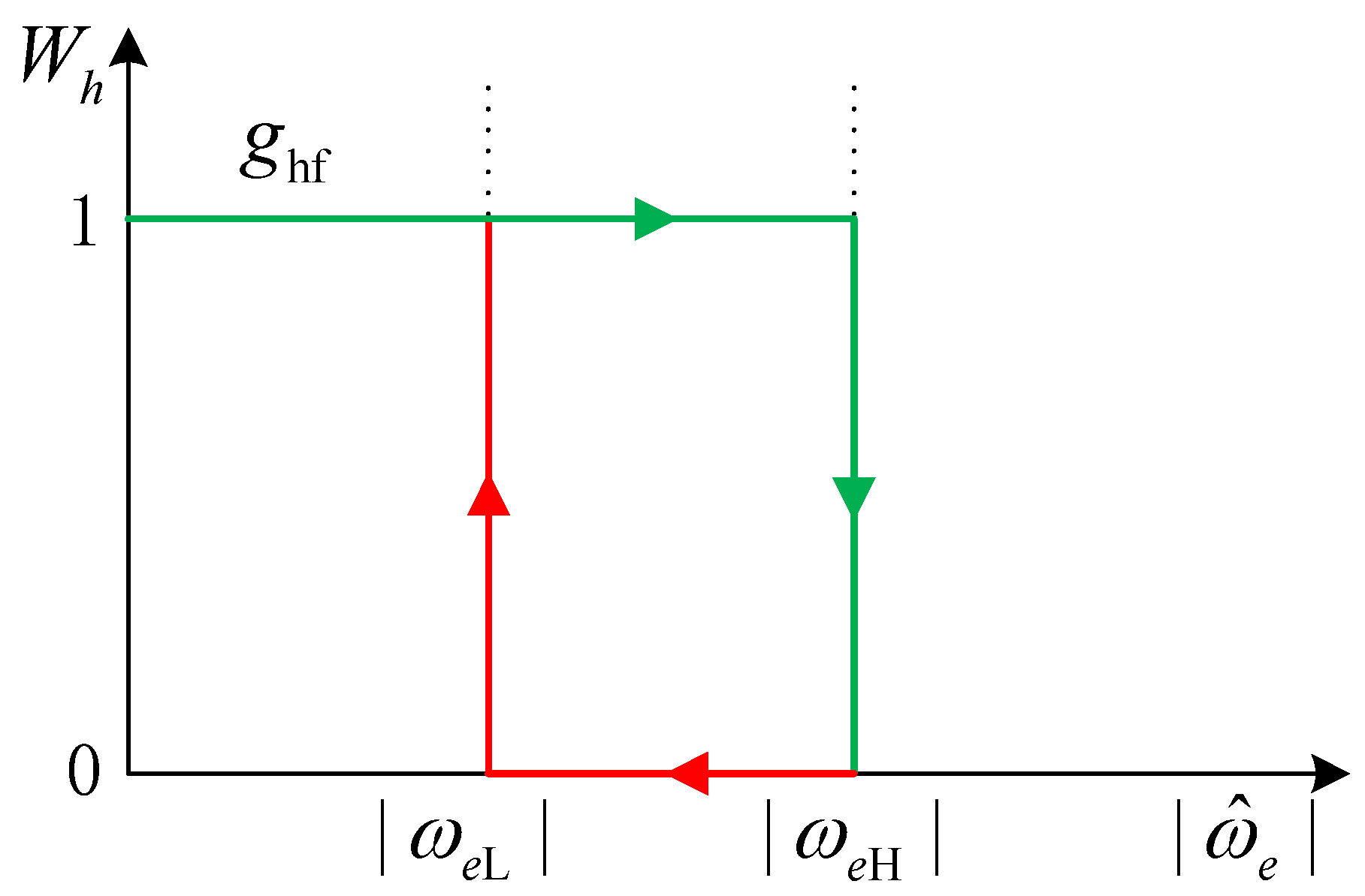
4.3. Hysteresis Loop Switching Method
5. Conclusions
- The high-frequency signal injection method has many advantages, but there are also problems of long convergence time, poor dynamic performance and small stability range. For compound control, the advantages of the high-frequency signal injection method inherit many disadvantages, which can have more or less impact on the estimation accuracy and other aspects in the compound control process. Therefore more advanced high-frequency signal injection methods should be studied to improve the reliability of the dynamic range of motor compound control estimation.
- I/F control is simple in structure, easy to implement, and has the advantages of smooth start-up and no current overcharge. It is the current start-up strategy for most position sensor-free control at medium and high speeds. However, the basic I/f control strategy is an open-loop scheme with disadvantages, such as the current amplitude and frequency cannot be automatically adjusted, and there is a tendency to lose steps, and the speed is easily disturbed, so its improvement will largely improve the performance of the compound control.
- There is a wide variety of control strategies for position sensorless control at high speeds, each with its own advantages, but also some shortcomings. So, the improvement of such algorithms will greatly improve the performance of the current compound control.
- Switching algorithms play a pivotal role in compound control. In the current research field of compound control, whether based on HF control or I/F control, switching strategies are required. Most of the switching algorithms commonly used today have the advantages of, for example, simpler methods and relatively stable algorithm switching, but their switching smoothness is not ideal, which means that the existing switching algorithms should be improved to achieve smoother and more stable switching, or smoother and more stable switching algorithms should be developed to meet the current high demand for motor position estimation.
Author Contributions
Funding
Data Availability Statement
Conflicts of Interest
References
- Li, Y.; Wu, H.; Xu, X.; Sun, X.; Zhao, J. Rotor Position Estimation Approaches for Sensorless Control of Permanent Magnet Traction Motor in Electric Vehicles: A Review. World Electr. Veh. J. 2021, 12, 9. [Google Scholar] [CrossRef]
- Jiang, H.B.; Li, A.X.; Ma, S.D.; Chen, L. Design and performance analysis of airflow energy recovery device of electric vehicle. J. Jiangsu Univ. 2017, 38, 125–132. [Google Scholar]
- Liu, C.H.; Luo, Y.X. Overview of Advanced Control Strategies for Electric Machines. Chin. J. Electr. Eng. 2017, 3, 53–61. [Google Scholar]
- Li, S.Q.; Ding, X.M.; Yu, B. Optimal control strategy of efficiency for dual motor coupling drive system of pure electric vehicle. J. Jiangsu Univ. 2022, 43, 1–7. [Google Scholar]
- Zhang, H.; Liu, W.G.; Chen, Z.; Mao, S.; Meng, T.; Peng, J.C.; Jiao, N.F. A Time-Delay Compensation Method for IPMSM Hybrid Sensorless Drives in Rail Transit Applications. IEEE Trans. Ind. Electron. 2019, 66, 6715–6726. [Google Scholar] [CrossRef]
- Li, Y.; Wu, H.; Zhang, B.H. Frontier techniques and prospect of in-wheel motor for electric vehicle. J. Jiangsu Univ. 2019, 40, 261–268. [Google Scholar]
- Xue, H.T.; Zhou, Y.; Wang, M.; Li, Z.X. Fault diagnosis method for in-wheel motor based on wolf pack algorithm. J. Jiangsu Univ. 2019, 40, 579–584. [Google Scholar]
- Liu, J.L.; Xiao, F.; Shen, Y.; Mai, Z.Q.; Li, C.R. Position-Sensorless Control Technology of Permanent-Magnet Synchronous Motor-a Review. Trans. China Electrotech. Soc. 2017, 32, 76–88. [Google Scholar]
- Li, J.M.; He, R. Optimization design and performance analysis of dual-rotor in-wheel motor based on parameter sensitivity. J. Jiangsu Univ. 2020, 41, 640–647. [Google Scholar]
- Sun, X.D.; Cao, J.H.; Lei, G.; Guo, Y.G.; Zhu, J.G. Speed Sensorless Control for Permanent Magnet Synchronous Motors Based on Finite Position Set. IEEE Trans. Ind. Electr. 2020, 67, 6089–6100. [Google Scholar] [CrossRef]
- Wu, D.R.; Tian, S.P. New control strategy of motor for pure electric vehicle based on TLGI technology. J. Jiangsu Univ. 2021, 42, 9–14. [Google Scholar]
- Guo, J.G.; Dog, H.X.; Sheng, W.H.; Tu, C. Optimum control strategy of regenerative braking energy for electric vehicle. J. Jiangsu Univ. 2018, 39, 132–138. [Google Scholar]
- Zhang, L.; Zhu, X.Y.; Gao, J.; Mao, Y. Design and Analysis of New Five-Phase Flux-Intensifying Fault-Tolerant Interior-Permanent-Magnet Motor for Sensorless Operation. IEEE Trans. Ind. Electron. 2020, 67, 6055–6065. [Google Scholar] [CrossRef]
- Wang, G.; Valla, M.; Solsona, J. Position sensorless permanent magnet synchronous machine drives—A review. IEEE Trans. Ind. Electron. 2019, 67, 5830–5842. [Google Scholar] [CrossRef]
- Mohan, H.; Pathak, M.K.; Dwivedi, S.K. Sensorless control of electric drives–a technological review. IETE Tech. Rev. 2020, 37, 504–528. [Google Scholar] [CrossRef]
- Lin, T.C.; Zhu, Z.Q. Sensorless operation capability of surface-mounted permanent-magnet machine based on high-frequency signal injection methods. IEEE Trans. Ind. Appl. 2015, 51, 2161–2171. [Google Scholar] [CrossRef]
- Liu, Y.; Zhou, B.; Li, S.; Feng, Y. Initial Rotor Position Detection of Surface Mounted Permanent Magnet Synchronous Motor. Proc. CSEE 2011, 31, 48–54. [Google Scholar]
- Liu, J.M.; Zhu, Z.Q. Sensorless control strategy by square aveform high-frequency pulsating signal injection into stationary reference frame. IEEE J. Emerg. Sel. Top. Power Electron. 2014, 2, 171–180. [Google Scholar] [CrossRef]
- Zhou, T.; Jiang, Q. Overview of Sensorless Control Technology for Full Speed Range Permanent Magnet Synchronous Motors. Electron. Sci. Technol. 2021, 34, 59–69. [Google Scholar]
- Xu, X.; Mi, J.; Wang, F.; Ma, S.D.; Tao, T. Design of differential braking control system of travel trailer based on multi-objective PID. J. Jiangsu Univ. 2020, 41, 172–180. [Google Scholar]
- Yoon, Y.D.; Sul, S.K.; Morimoto, S.; Ide, K. High-Bandwidth Sensorless Algorithm for AC Machines Based on Square-Wave-Type Voltage Injection. IEEE Trans. Ind. Appl. 2011, 47, 1361–1370. [Google Scholar] [CrossRef]
- Lu, J.D.; Liu, J.L.; Wei, L.C. Estimation of the Initial Rotor Position for Permanent Magnet Synchronous Motors. Trans. China Electrotech. Soc. 2015, 30, 105–111. [Google Scholar]
- Zhou, Y.J.; Cai, M.F. Initial rotor position inspection of PMSM based on rotating high frequency voltage signal injection. Electr. Mach. Control. 2010, 14, 68–72. [Google Scholar]
- Chen, S.H.; Liu, G.; Zhu, L.Q. Sensorless Start-Up Control Strategy for a 315 kW High-Speed Magnetic Suspension BLDC Motor with Small Inductance and Non-ideal Back-EMF. IEEE Trans. Ind. Electron. 2018, 66, 1703–1714. [Google Scholar] [CrossRef]
- Damodharan, P.; Vasudevan, K. Sensorless Brushless DC Motor Drive Based on the Zero-Crossing Detection of Back Electromotive Force (EMF) From the Line Voltage Difference. IEEE Trans. Energy Convers. 2010, 25, 661–668. [Google Scholar] [CrossRef]
- Zhang, G.Q.; Wang, G.L.; Xu, D.G.; Fu, Y.; Ni, R.G. Adaptive Notch Filter Based Rotor Position Estimation for Interior Permanent Magnet. Proc. CSEE. 2016, 36, 2521–2527. [Google Scholar]
- Wang, D.F.; Zhu, Y.Q.; Jin, Y.; Liu, Z.Q. A novel research on detecting position of brushless DC motors. Trans. China Electrotech. Soc. 2013, 28, 139–144. [Google Scholar]
- Shen, J.X.; Iwasaki, S. Sensorless control of ultrahigh-speed PM brushless motor using PLL and third-harmonic back EMF. IEEE Trans. Ind. Electron. 2006, 53, 421–428. [Google Scholar] [CrossRef]
- Wang, D.F.; Zhu, Y.Q.; Jin, Y.; Zhao, G.Y. Tentative Strategy of Starting Sensorless BLDCM with the Method of Integrating the Back EMF. Trans. China Electrotech. Soc. 2012, 27, 178–184. [Google Scholar]
- Chen, Z.Q.; Tomita, M.; Doki, S. An extended electromotive force model for sensorless control of interior permanent- magnet synchronous motors. IEEE Trans. Ind. Electron. 2003, 50, 288–295. [Google Scholar] [CrossRef]
- Lee, K.G.; Lee, J.S.; Lee, K.B. Wide-range sensorless control for SPMSM using an improved full-order flux observer. J. Power Electron. 2015, 15, 721–729. [Google Scholar] [CrossRef] [Green Version]
- Qiu, T.F.; Wen, X.H.; Zaho, F.; Wang, Y.X. Design Strategy of Permanent Magnet Flux Linkage Adaptive Observer for Permanent Magnet Synchronous Motor. Proc. CSEE 2015, 35, 2287–2294. [Google Scholar]
- Zhu, Y.; Cheng, M.; Hua, W.; Zhang, B.F.; Wang, W. Sensorless control for electrical variable transmission based on sliding mode model reference adaptive system. Trans. China Electrotech. Soc. 2015, 30, 64–72. [Google Scholar]
- Rai, R.; Shukla, S.; Singh, B. Electromagnetic Torque-Based Model Reference Adaptive System Speed Estimator for Sensorless Surface Mount Permanent Magnet Synchronous Motor Drive. IEEE Trans. Ind. Inform. 2020, 16, 4714–4725. [Google Scholar] [CrossRef]
- Hu, W.H.; Wang, Y.; Li, M.X.; Li, M.; Wang, Z.A. Research on sensorless control strategy of direct drive multiphase PMSG wind power generation system based on MRAS. Power Syst. Prot. Control. 2014, 42, 118–124. [Google Scholar]
- Li, Y.H.; Zhao, Y.Q. Path tracking of 4WIS autonomous vehicle based on double-layer control strategy. J. Jiangsu Univ. 2022, 43, 386–393. [Google Scholar]
- Zhang, H.S.; Wang, P.; Han, B.C. Rotor Position Measurement for High-speed Permanent Magnet Synchronous Motors Based on Fuzzy PI MRAS. Proc. CSEE 2014, 34, 1889–1896. [Google Scholar]
- Yao, X.L.; Ding, D.D.; Yang, Y.; Ge, W.J.; Wu, M.Y. Failure compensation control design of adaptive actuator for vehicle robot driver. J. Jiangsu Univ. 2021, 42, 642–647. [Google Scholar]
- Xu, B.; Shen, X.K.; Ji, W.; Shi, G.D. Adaptive Nonsingular Terminal Sliding Model Control for Permanent Magnet Synchronous Motor Based on Disturbance Observer. IEEE Access 2018, 6, 48913–48920. [Google Scholar] [CrossRef]
- Zhang, X.; Guo, L.L.; Yang, S.Y.; Cao, R.X. Speed Sensorless Control of Permanent Magnet Synchronous Generators. Proc. CSEE 2014, 34, 3440–3447. [Google Scholar]
- Su, J.Y.; Li, T.C.; Yang, G.J. PMSM sensorless control based on four-order hybrid sliding mode observer. Proc. CSEE 2009, 29, 98–103. [Google Scholar]
- Zhao, Y.; Qiao, W.; Wu, L. Improved Rotor Position and Speed Estimators for Sensorless Control of Interior Permanent- Magnet Synchronous Machines. IEEE J. Emerg. Sel. Top. Power Electron. 2014, 2, 627–639. [Google Scholar] [CrossRef]
- Zhang, Z.Y.; Lin, M.Y.; Zhou, G.Q. Anti-reverse rotation startup and smoothly switching of sensorless brushless DC motor. Trans. China Electrotech. Soc. 2009, 24, 26–32. [Google Scholar]
- Wu, C.; Qi, R.; Li, B.Q.; Ma, D.L. Whole Speed Range Sensorless Control of Permanent Magnet Synchronous Motor Considering Saturation Effect. Trans. China Electrotech. Soc. 2017, 32, 171–179. [Google Scholar]
- Chen, S.Y.; Pi, Y.G. Position Sensorless Control for Permanent Magnet Synchronous Motor Based on Sliding Mode Observer and Sliding Mode Controller. Trans. China Electrotech. Soc. 2016, 31, 108–117. [Google Scholar]
- Wang, Z.; Lu, K.; Blaabjerg, F. A simple startup strategy based on current regulation for back-EMF-based sensorless control of PMSM. IEEE Trans. Power Electron. 2012, 27, 3817–3825. [Google Scholar] [CrossRef]
- Barnard, F.J.; Villet, W.T.; Kamper, M.J. Hybrid active-flux and arbitrary injection position sensorless control of reluctance synchronous machines. IEEE Trans. Ind. Appl. 2015, 51, 3899–3906. [Google Scholar] [CrossRef]
- Qin, F.; He, Y.K.; Jia, H.P. Investigationn of the Sensorless Control for PMSM Based on a Hybird Rotor Position Self-Sensing Approach. Proc. CSEE 2007, 27, 12–17. [Google Scholar]
- Xu, H.Z.; Xie, S.Y.; Zhang, L.S.; Wang, S.L. Investigation of hybrid sensorless control approach for dualrotor PMSM. Electr. Mach. Control. 2012, 16, 12–16. [Google Scholar]
- Antti, P.; Marko, H. Adaptation of motor parameters in sensorless PMSM drives. IEEE Trans. Ind. Appl. 2009, 45, 203–212. [Google Scholar]
- Jiang, H.B.; Zhu, C.; Tang, B.; Yin, C.H.; Hua, Y.F.; Xie, J. Lateral stability control of ECHBPS commercial vehicle based on extension active disturbance rejection. J. Jiangsu Univ. 2021, 42, 166–172. [Google Scholar]
- Li, Y.; Hu, H.; Qin, Z.C.; Wu, H. Sensorless control of permanent magnet in-wheel motor based on improved model reference adaptive strategy. J. Automot. Saf. Energy 2022, 13, 560–570. [Google Scholar]
- Yang, M.H.; Li, S.Q.; Li, Z.; Feng, B.; Li, J. Active disturbance rejection controller of direct torque for permanent magnet synchronous motor based on super-twisting sliding mode. J. Jiangsu Univ. 2022, 43, 680–684, 696. [Google Scholar]
- Jiang, H.B.; Cao, F.G.; Zhu, W.W. Control method of intelligent vehicles cluster motion based on SMC. J. Jiangsu Univ. 2018, 39, 385–390. [Google Scholar]
- Chen, M.S.; Hwang, Y.R.; Tomizuka, M. A state-dependent boundary layer design for sliding mode control. IEEE Trans. Autom. Control. 2010, 47, 1677–1681. [Google Scholar] [CrossRef]
- Zhang, J.C.; Wang, L.M.; Zou, X.J.; Song, W. Optimization control strategy of driving torque for slope-crossing of pure electric vehicles. J. Jiangsu Univ. 2021, 42, 506–512. [Google Scholar]
- Wang, G.L.; Li, Z.M.; Zhang, G.Q.; Yu, Y. Quadrature PLL-Based High-Order Sliding-Mode Observer for IPMSM Sensorless Control with Online MTPA Control Strategy. IEEE Trans. Energy Convers. 2013, 28, 214–224. [Google Scholar] [CrossRef]
- Li, R. Research on the Sensorless Control. Technique of Permanent Magnet Synchronous Motor; Zhejiang University: Hangzhou, China, 2012. [Google Scholar]
- Gilbert, F.; Rahman, M.F. Sensorless sliding-mode MTPA control of an IPM synchronous motor drive using a sliding-mode observer and HF signal injection. IEEE Trans. Ind. Electron. 2010, 57, 1270–1278. [Google Scholar]
- Wang, G.L.; Yang, R.F.; Xu, D.G. DSP-Based Control of Sensorless IPMSM Drives for Wide-Speed-Range Operation. IEEE Trans. Ind. Electron. 2013, 60, 720–727. [Google Scholar] [CrossRef]
- Zhou, L.Y.; Wang, S.J. Torque control of BLDCM based on predictive current control. J. Jiangsu Univ. 2015, 36, 79–86. [Google Scholar]
- Gupta, N.; Pandey, D.A.K. A Review: Sensorless Control of Brushless DC Motor; Esrsa Publications: Gandhinagar, India, 2012. [Google Scholar]
- Boldea, I.; Paicu, M.C.; Andreescu, G.D.; Blaabjerg, F. Active flux” DTFC-SVM sensorless control of IPMSM. IEEE Trans. Energy Convers. 2009, 24, 314–322. [Google Scholar] [CrossRef]
- Silva, C.; Asher, G.M.; Sumner, M. Hybrid rotor position observer for wide speed-range sensorless PM motor drives including zero speed. IEEE Trans. Ind. Electron. 2006, 53, 373–378. [Google Scholar] [CrossRef]
- Andreescu, G.D.; Pitic, C.I.; Blaabjerg, F.; Boldea, I. Combined Flux Observer with Signal Injection Enhancement for Wide Speed Range Sensorless Direct Torque Control of IPMSM Drives. IEEE Trans. Energy Convers. 2008, 23, 393–402. [Google Scholar] [CrossRef]
- Zhang, G.Q.; Wang, G.L.; Xu, D.G.; Yu, Y. Hybrid Sensorless Control Based on Single Position Observer Using Error Combination for Interior Permanent Magnet Synchronous Machine Drives. Proc. CSEE 2017, 37, 6077–6082. [Google Scholar]
- Qiu, X.; Huang, W.X.; Bu, F.F. Sensorless direct torque control of interior permanent magnet synchronous machines over wide speed range. Trans. China Electrotech. Soc. 2014, 29, 92–99. [Google Scholar]
- Ohnuma, T.; Makaino, Y.; Saitoh, R. Adaptive signal injection method combined with EEMF based position sensorless control of IPMSM drives. IEEJ J. Ind. Appl. 2014, 4, 914–918. [Google Scholar]
- Song, G.Y.; Li, J.L. A Sensorless Control for PMSM with combined IF and Improved Sliding Mode Observer. Electr. Mach. Control. 2020, 24, 63–72. [Google Scholar]
- Liu, J.L.; Xiao, F.; Mai, Z.Q.; Gao, S.; Yu, X.W. Hybrid Position-Sensorless Control Scheme for PMSM Based on Combination of IF Control and Sliding Mode Observer. Trans. China Electrotech. Soc. 2018, 33, 919–929. [Google Scholar]
- Wang, M.; Yang, J.Q.; Zhang, X.; Zhu, C.S. An I/f Control Method with Closed-loop Regulation of Current Vector for Surface Permanent Magnet Synchronous Motor Drives. Proc. CSEE 2015, 35, 2513–2521. [Google Scholar]
- Tang, Q.P.; Chen, D.X.; He, X.N. Integration of Improved Flux Linkage Observer and I-f Starting Method for Wide-Speed-Range Sensorless SPMSM Drives. IEEE Trans. Power Electron. 2020, 35, 8374–8383. [Google Scholar] [CrossRef]
- Tao, W.; Liu, Z.Q. Seat suspension control of wheel loader based on damping state switching. J. Jiangsu Univ. 2019, 40, 504–510. [Google Scholar]
- Zhao, Q.J.; Liao, Z.L.; Zhang, Y.Y.; Cai, L.C. Research on Position Sensorless Control of Hub Motor in Full Speed Range. Acta Armamentarii 2019, 40, 915–926. [Google Scholar]
- Wu, D.D.; Ge, Q.; Xu, X.F.; Qiu, B.Y. Grid-connected control strategy of virtual synchronous generator based on virtual power. J. Jiangsu Univ. 2022, 43, 458–463. [Google Scholar]
- Panin, S.V.; Bogdanov, A.A.; Eremin, A.V.; Buslovich, D.G.; Alexenko, V.O. Estimating Low- and High-Cyclic Fatigue of Polyimide-CF-PTFE Composite through Variation of Mechanical Hysteresis Loops. Materials 2022, 15, 4656. [Google Scholar] [CrossRef]
- Wu, C.; Fu, Z.J.; Sun, M.X.; Liu, Z. Sensorless Control of PMSM in All Speed Range Based on Extended State Observer for Load Toque Compensation. Trans. China Electrotech. Soc. 2020, 35 (Suppl. S1), 172–181. [Google Scholar]


| Algorithms | Reference | Description |
|---|---|---|
| high frequency (HF) injection | [16,17,18,19,20,21,22,23] | The HF injection method is not reliant on the spatial protrusion of the tracking rotor rather than the mathematical equation of the motor, which addresses the sensitivity to the change in motor parameters and leads to a strong robustness. Yet the filter is needed, which has the defects of low signal-to-noise ratio and large phase lag in signal processing. |
| including direct calculation | [24,25,26,27] | This method does not depend on the speed of the motor, but it needs to increase the integral circuit and increase the hardware complexity and may bring additional integral error. |
| back-electromotive force (EMF) | [28,29,30] | The realization is simple, but the back EMF signal is small when the motor is low speed or static. The back EMF needs to be filtered, which will cause phase shift of the signal. |
| flux estimation | [31,32] | The rotor flux of the motor cannot be detected directly. It is necessary to measure the phase voltage and current of the motor, and to establish the function equation, which is directly related to the rotor flux without relying on the rotor speed. The calculation is large. |
| model reference adaptation system (MRAS) | [33,34,35,36,37,38] | The position observation is based on the accuracy of the reference model, and the accuracy of the parameters of the reference model itself directly affect the effectiveness of the identification. |
| sliding mode observer (SMO) | [39,40,41,42] | It can solve the problem that the motor is difficult to control at high speed and heavy load, and has strong robustness, but it needs a large amount of operation. |
Disclaimer/Publisher’s Note: The statements, opinions and data contained in all publications are solely those of the individual author(s) and contributor(s) and not of MDPI and/or the editor(s). MDPI and/or the editor(s) disclaim responsibility for any injury to people or property resulting from any ideas, methods, instructions or products referred to in the content. |
© 2023 by the authors. Licensee MDPI, Basel, Switzerland. This article is an open access article distributed under the terms and conditions of the Creative Commons Attribution (CC BY) license (https://creativecommons.org/licenses/by/4.0/).
Share and Cite
Li, Y.; Hu, H.; Shi, P. A Review of Position Sensorless Compound Control for PMSM Drives. World Electr. Veh. J. 2023, 14, 34. https://doi.org/10.3390/wevj14020034
Li Y, Hu H, Shi P. A Review of Position Sensorless Compound Control for PMSM Drives. World Electric Vehicle Journal. 2023; 14(2):34. https://doi.org/10.3390/wevj14020034
Chicago/Turabian StyleLi, Yong, Han Hu, and Peicheng Shi. 2023. "A Review of Position Sensorless Compound Control for PMSM Drives" World Electric Vehicle Journal 14, no. 2: 34. https://doi.org/10.3390/wevj14020034