Article

Research on Control Method of Dual-Motor Load Simulator

College of Electronic Information and Automation, Civil Aviation University of China, Tianjin 300300, China
*
Author to whom correspondence should be addressed.
World Electr. Veh. J. 2023, 14(2), 28; https://doi.org/10.3390/wevj14020028
Submission received: 2 December 2022 / Revised: 15 January 2023 / Accepted: 18 January 2023 / Published: 23 January 2023
(This article belongs to the Special Issue Electrical Machines Design and Control in Electric Vehicles)

Abstract

:
Aiming at the output torque error of a steering gear electric load simulator caused by excess torque and backlash interference, an electric load simulator based on double-motor loading is designed. The double-motor loading mode is adopted in the structure, the mathematical model is established, and the sources of excess torque and backlash interference are analyzed. In the control strategy, firstly, a torque controller is designed as a feedback controller based on the improved error symbol robust integral control method, and then a backlash interference compensator is designed as a feedforward controller based on the drive redundancy strategy. Finally, a dual motor speed synchronization controller is designed based on the improved cross coupling control method to ensure the stable operation of the torque controller and backlash compensator in the dual-motor system. The simulation results show that the compound control method can reduce the tracking error to 1.13%, 4.44% less than the PID control method. The tracking error is only 1.54% in the case of redundant torque, backlash, and different parameters of dual motors. The method proposed in this paper can still output loading torque with high accuracy.

1. Introduction

With the rise of electric vehicles and the development of driverless technology, people have conducted more in-depth research on wheel motors and hub motors and have more requirements for their performance. The electric load simulator of a steering gear is a hardware in the loop simulation equipment that can simulate the torque of the steering gear by the loading motor under laboratory conditions [1,2]. Testing the steering gear by simulating the torque can not only avoid damage to the steering gear caused by the traditional full object experiment, but also improve the controllability and repeatability of the steering gear testing experiment [3,4]. Its load simulation function can also be used in the motor test, which can comprehensively test the motor performance before the full physical experiment, so as to save money and shorten the research and development cycle.
Since the steering gear is directly connected to the loading motor, the redundant torque caused by the active motion of the steering gear and the nonlinear disturbance between the mechanical structures will affect the accuracy of the load simulator’s output loading torque, thus affecting the reliability of the system’s experimental results [5,6]. Therefore, the key problem of load simulator research is to study the disturbance of load torque caused by redundant torque and nonlinear disturbance and to restrain it.
The traditional load simulator uses PID control, but the PID control can not suppress the redundant moment, and the output moment accuracy is low. Gu et al. introduced a cerebellar model articulation controller (CMAC) to tune the parameters of the PD controller [7]. The experimental results show that the trained neural network controller can realize self-tuning and improve the output moment accuracy at the same time. On this basis, Bo et al. proposed a semi-fuzzy CMAC controller, which saved storage space and reduced computational load, compressed storage space, improved computational speed, and smoothed CMAC output [8]. Dai et al. proposed a composite controller based on inversion sliding mode control design. Based on the idea of inversion design, the electric load simulator was decomposed into a load moment subsystem and a permanent magnet synchronous motor drive subsystem, and a proportional approach sliding mode control law and nonsingular terminal sliding mode control law were designed, respectively [9]. Experiments show that it is more robust than the improved PID control. Wang et al. designed a proportional resonance control design controller for high-frequency loading problems [10]. Experiments show that the controller can still achieve high-precision loading of loading moments under high-frequency preset moment conditions. Liu et al. used the swarm intelligence algorithm to set parameters of the active disturbance rejection controller, and used the improved whale optimization algorithm to adjust parameters of the controller [11]. The simulation shows that the method can suppress the interference of the extra moment on the loading moment. Liu et al., based on linear active disturbance rejection control, designed an ELS inner loop controller based on an electromechanical model by measuring the torque to reduce the complexity of the estimator [12]. A phase-locked loop observer is introduced to suppress the negative effects of measurement errors so as to obtain good residual torque suppression performance and control system dynamic characteristics. As the load simulator works periodically, iterative learning control (ILC) is applied to the electric load simulator. Niu et al. designed an improved ILC with sinusoidal cycle iteration [13]. Experiments show that this method can effectively suppress the unwanted moment interference. In a load simulator with time delay, Dai et al. applied an iterative learning PID controller. By iteratively adjusting the amount of control without modeling and analyzing the time delay, the experiment proves that this method can effectively improve the control accuracy [14]. The nonlinear interference of the system includes friction and backlash, and researchers are paying more attention to the suppression of friction. Li Cheng-cheng and others proposed an improved cuckoo algorithm, and the experiment proved that the method can effectively identify each parameter in the friction model [15]. Pan Wei-dong and others proposed to use the genetic algorithm to identify friction model parameters, and realized the suppression of friction and excess torque through friction feedforward compensation and variable gain PID [16].
It can be seen from the above analysis that reference [9,10,11,12] requires accurate model parameters of the system when designing the controller. However, due to the problems of output lag and mechanical structure coupling of load simulator, it is difficult to establish an accurate mathematical model. Therefore, control methods such as [13,14,15], which only require system input and output data, are more suitable for solving the output accuracy problem of the load simulator, and the existing research mainly focuses on friction suppression, and the research on backlash interference in nonlinear interference is relatively small. How to reduce the influence of backlash interference on the output torque is also an urgent problem in the research of load simulators.
Robust integral of signal of error (RISE) control is a data-driven control method that has a simple structure and can control the system without the need for detailed system parameters and modeling. It has been widely used in underwater vehicles, automatic flight systems, multi-robot system trajectory tracking, and other fields [17,18,19,20,21,22,23]. In order to improve the loading accuracy and dynamic performance of the load simulator under the interference of redundant torque and backlash, a dual-motor loading structure is designed, and a composite control strategy suitable for this structure is proposed. Based on the improved RISE control and drive redundancy strategy, the interference of redundant torque and backlash on the loading torque are solved, respectively, and the system output accuracy is improved. On this basis, a dual-motor speed synchronization controller is designed to ensure the stable operation of the system, and the effectiveness of the control strategy is proved through experiments.
This paper presents a new type of load simulator with a dual-motor structure. The dual-motor structure can effectively suppress the interference of backlash to the load simulator. At the same time, combined with the improved RISE controller and the dual-motor synchronous controller, high-precision torque loading can still be achieved when the parameters of dual motors are different.
The rest of this article consists of the following: In Section 2, an introduction to the working principle of the electric load simulator and the dual-motor load simulator is presented. In Section 3, The mathematical model of the dual-motor load simulator is presented. In Section 4, in order to suppress load moment tracking errors caused by different parameters of redundant torques, teeth gaps, and dual motors, the control methods presented in this paper are presented in detail. Section 5 concludes the simulation results and presents directions for future work.

2. Working Principle of Electric Load Simulator and Dual-Motor Load Simulator

The traditional single-motor load simulator structure consists of the loading part and the tested steering gear part, as shown in Figure 1. When the system is running, the industrial personal computer (IPC) outputs the preset torque signal to the loading part, and the signal is processed by the motor controller and motor driver to drive the loading motor to output torque to the tested steering gear. At the same time, the IPC collects the speed signal and torque signal of the tested steering gear under the influence of the loading torque to evaluate the performance of the steering gear.
The backlash interference in the system will cause the output lag, and then affect the accuracy of the loading torque. The traditional single-shaft drive system of the load simulator with backlash compensation method cannot completely eliminate the impact of backlash. The dual-shaft drive structure can not only share the load through the joint drive of two motors, but also eliminate the impact of backlash on the system output through electromechanical control [24]. Therefore, the load simulator of the dual-motor driving steering gear is proposed, as shown in Figure 2.
Compared with the traditional single-motor load simulator, the dual-motor load simulator has two improvements:
(1)
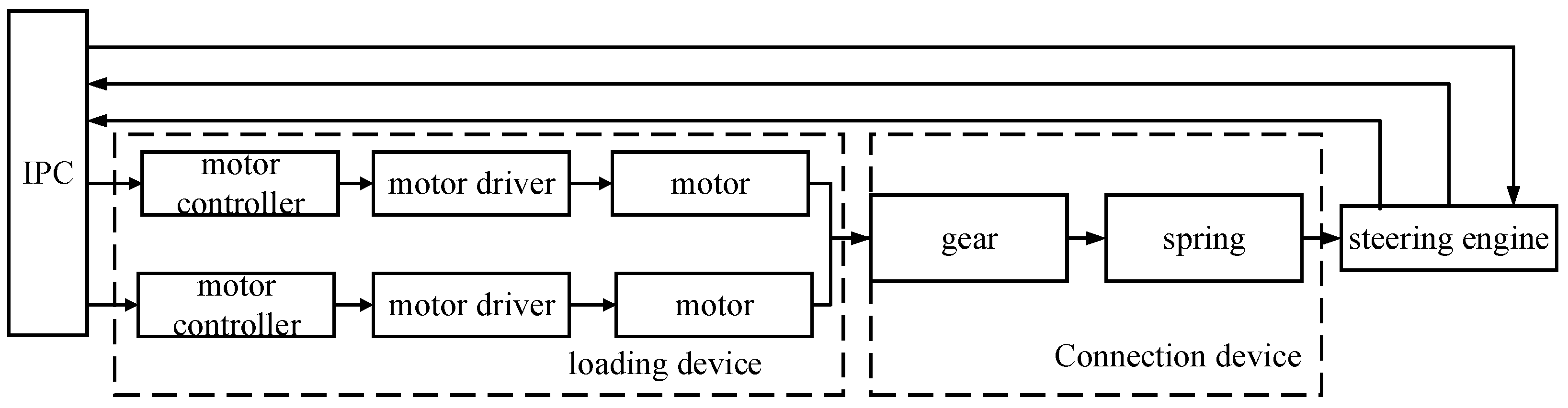
The torque loading part is changed from single-motor to double-motor. It can not only share the loading task with two motors, but also restrain the interference caused by backlash with the dual-motor drive redundancy algorithm.
(2)
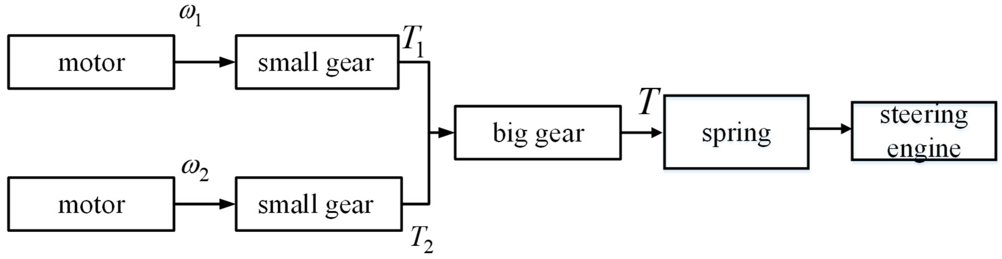
The loading torque is not directly output to the tested steering gear. Instead, the resultant torque is first output through the gear structure. The schematic diagram of the gear drive is shown in Figure 3. The two small gears rotate at the same time and push the big gear to rotate together. The big gear is connected with the metal rubber buffer spring and outputs the simulated hinge torque to the tested steering gear.
Here is how the dual-motor load simulator works:
(1)
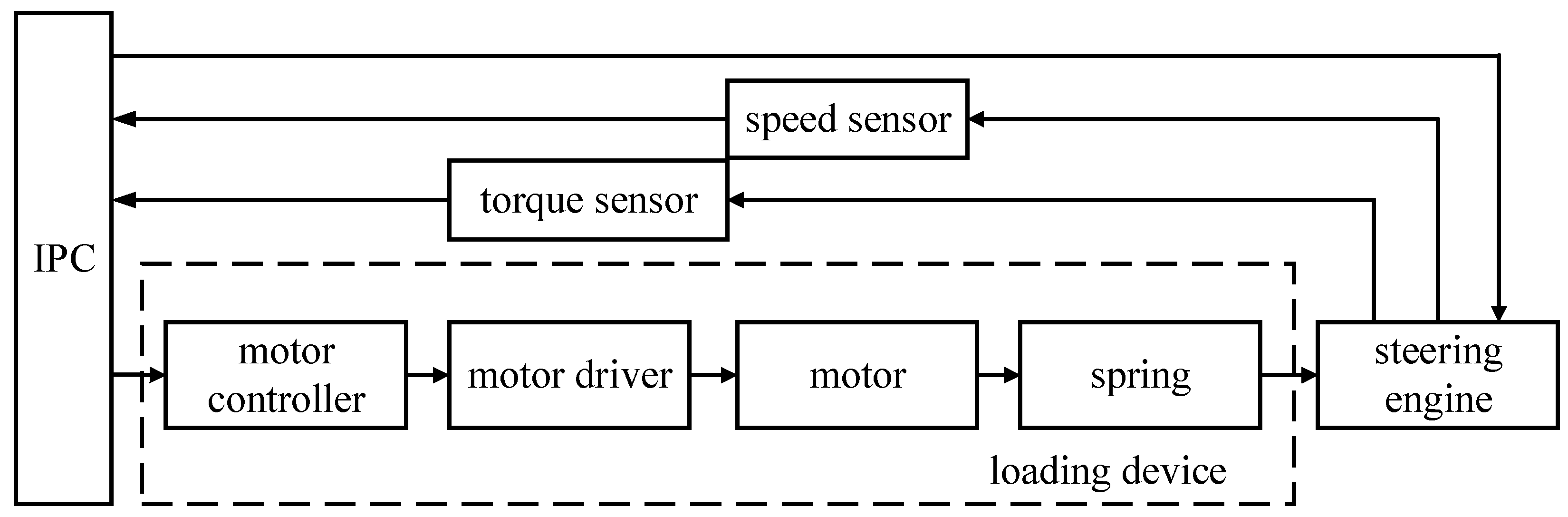
The industrial computer outputs the preset torque signal to the motor controller of each motor, and the control signal makes each loading motor output the loading torque to the gear through the motor driver.
(2)
The two pinions jointly drive the big gear to rotate, and the combined loading torque is output to the tested steering gear through the metal rubber buffer spring.
(3)
The IPC independently controls the movement of the tested steering gear and receives the steering gear sensor signal to evaluate the performance of the steering gear, and completes the steering gear test experiment.

3. Mathematical Model of Dual Motor Load Simulator

Due to the coupling between the loading motor and the tested steering gear, it is difficult to model the system of the steering gear electric load simulator. The existing mathematical models are traditional single-motor models, and there is no dual-motor loading load simulator. Therefore, in order to realize the ability of the load simulator to simulate the complex air torque in actual work, it is necessary to establish a mathematical model of the load simulator according to the dual-motor loading characteristics, analyze the mechanism of excess torque generation and the mechanism of backlash interference, and provide a reliable source of information for the design of the controller. Compared with the traditional electric load simulator of the steering gear, two improvements are proposed in modeling:
(1)
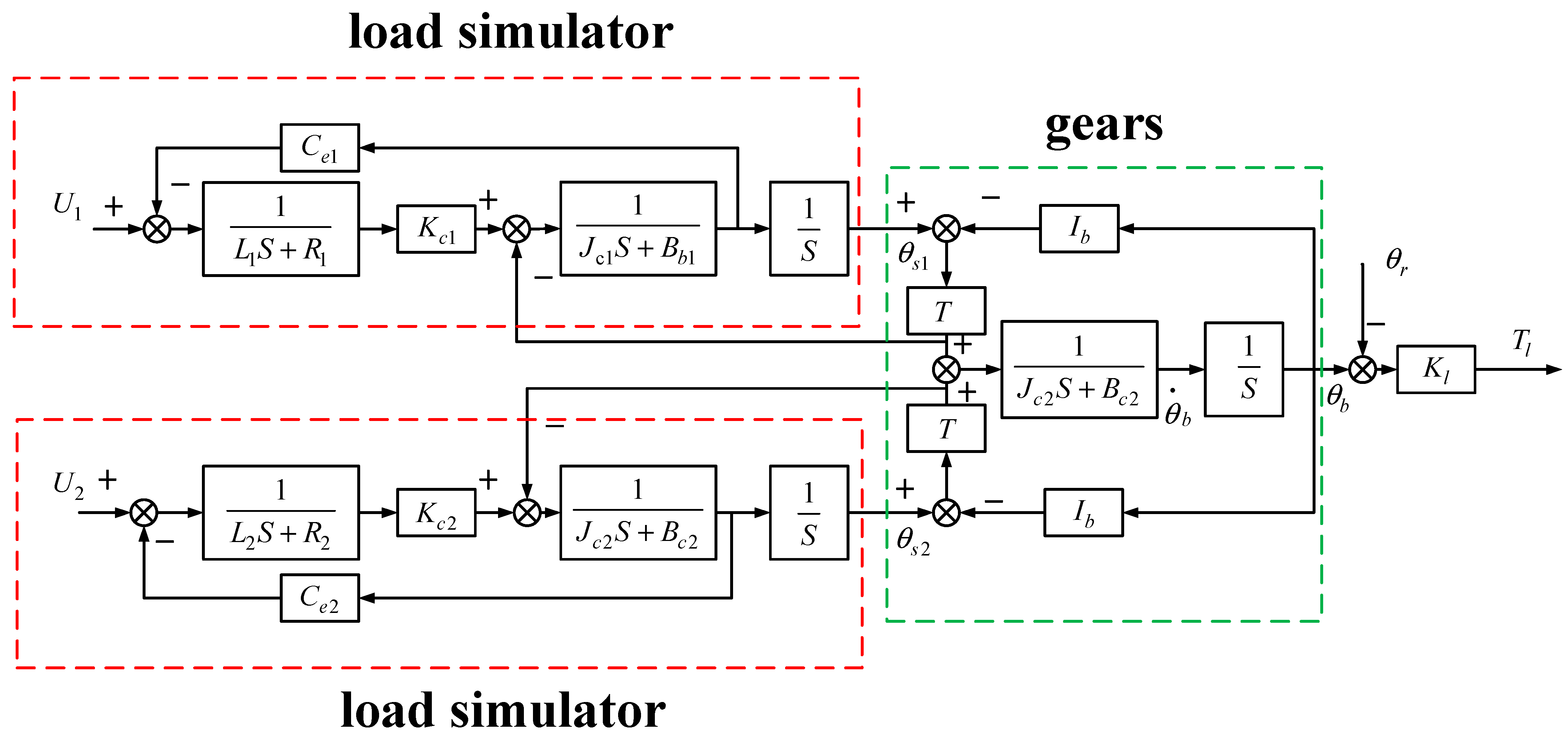
The structure of the double-motor load simulator is established, and the gear connection structure is introduced to model and analyze it. At the same time, irrelevant factors such as viscous friction coefficient are ignored. The influence of redundant torque and backlash interference on the loading torque are highlighted;
(2)
The metal rubber buffer spring is introduced into the system to improve the connection between the loading motor and the tested steering gear. Compared with the commonly used spring rod structure, the buffer spring can realize continuous loading with variable stiffness and has better practical value.
Considering the difference in motor parameters in the dual-motor structure, the subscript n is used to represent various parameters of different motors. Considering that the load element in the load simulator is a DC brush torque motor, the formula of the motor armature circuit voltage balance and motor torque balance is
K T n i n = ( J n + J j n ) θ ¨ n + B n θ ˙ n + M s n U n = i n R n + L n i ˙ n + C e n θ ˙ n n = 1 , 2
where θ ¨ n and θ ˙ n are the second derivative and the first derivative of the nth motor output angle, respectively. K T n , i n , J n , J j n , B n are the torque coefficient of the nth motor, armature current, moment of inertia of the nth motor, moment of inertia of the nth reducer, and equivalent viscous friction coefficient of the nth motor, respectively. M s n is the elastic torque between the nth motor shaft and the pinion. U n , R n , L n , C e n are the armature voltage, armature resistance, armature inductance, and back EMF coefficient of the nth motor, respectively.
The pinion torque balance formula and speed are expressed as
θ n = θ s n M s n = J s n θ ¨ s n + B s n θ ˙ s n + M sb n M sb n = K t n ( θ s n I b θ b ) + C b n ( θ ˙ s n I b θ ˙ b ) n = 1 , 2
where θ s n , M s b n are the angle of the pinion and the elastic moment between the big and small gears, respectively; B s n , K t n , C b n are, respectively, the viscous friction coefficient of the nth pinion, the elastic coefficient between the nth pinion and the big gear, and the damping coefficient between the nth pinion and the big gear; I b is the transmission ratio of the big and small gears.
The torque balance formula of the large gear is expressed as
M = I b ( M sb 1 + M sb 2 )
M D 2 = J b θ ¨ b + B b θ ˙ b
where M is the torque of the big gear; J b , B b are, respectively, the moment of inertia and viscous friction coefficient of the big gear. D 2 is the surplus force caused by the active motion of the steering gear.
By introducing Equation (2) into Equation (1), we can obtain
U n = i n R n + L n i · n + C e n θ ˙ s n
K T n i n = ( J n + J j n ) θ ¨ n + B n θ ˙ n + J s n θ ¨ s n + B s n θ ˙ s n + M sb n
According to Equation (6),
K T n i n = θ ¨ s n ( J n + J j n + J s n ) + θ ˙ s n ( B n + B s n ) + K t n ( θ s n I b θ b ) + C b n ( θ · s n I b θ · b )
Let J n + J j n + J s n = J c n , B n + B s n = B c n , K T n = K c n .
Ignoring the viscous friction between gears, Equation (7) can be changed into
J c n θ ¨ s n + B c n θ ˙ s n + K t n ( θ s n I b θ b ) = K c n i n
In conclusion, the mathematical model of the double-motor electric load simulator without backlash can be obtained as follows:
U 1 = i 1 R 1 + L i 1 · + C e 1 θ ˙ s 1 U 2 = i 2 R 2 + L i · 2 + C e 2 θ ˙ s 2 K c 1 i 1 = J c 1 θ ¨ s 1 + B c 1 θ ˙ s 1 + K t 1 ( θ s 1 I b θ b ) K c 2 i 2 = J c 2 θ ¨ s 2 + B c 2 θ ˙ s 2 + K t 2 ( θ s 2 I b θ b ) J b θ ¨ b + B b θ ˙ b + D = I b ( K t 1 ( θ s 1 I b θ b ) + K t 2 ( θ s 2 I b θ b ) ) n = 1 , 2
The commonly used mathematical models of backlash in transmission system can be divided into three categories: the hysteresis model, dead zone model, and vibration impact model. The dead zone model not only considers the influence of system damping, but also ignores the nonlinear time-varying parameters, which is most suitable for describing the characteristics of the backlash of the load simulator system. The mathematical expression of the backlash dead zone model is
T ( f ( t ) ) = f ( t ) Δ t Δ 0 Δ < t < Δ f ( t ) + Δ t Δ
where Δ is the width of the backlash. It means that the width of the backlash is within the range of the backlash, and the system has no position output, so it is called the dead zone model of the backlash. f(t) is the system outputs value before the backlash, and T(f(t)) is the actual output value after the backlash. In the double-motor electric load simulator, the backlash exists between the big and small gears, which can be obtained from Equation (9):
K c 1 i 1 = J c 1 θ ¨ s 1 + B c 1 θ ˙ s 1 + T ( K t 1 ( θ s 1 I b θ b ) ) K c 2 i 2 = J c 2 θ ¨ s 2 + B c 2 θ ˙ s 2 + T ( K t 2 ( θ s 2 I b θ b ) )
According to Equations (9) and (10), the mathematical model of the double-motor electric load simulator with clearance is
U 1 = i 1 R 1 + L i · 1 + C e 1 θ ˙ s 1 U 2 = i 2 R 2 + L i · 2 + C e 2 θ ˙ s 2 K c 1 i 1 = J c 1 θ ¨ s 1 + B c 1 θ ˙ s 1 + T ( K t 1 ( θ s 1 I b θ b ) ) K c 2 i 2 = J c 2 θ ¨ s 2 + B c 2 θ ˙ s 2 + T ( K t 2 ( θ s 2 I b θ b ) ) J b θ ¨ b + B b θ ˙ b + D = I b ( K t 1 ( θ s 1 I b θ b ) +           K t 2 ( θ s 2 I b θ b ) )
The metal rubber buffer spring is arranged between the steering gear and the gear mechanism, which can suppress high-frequency interference torque. The torque of the steering gear is essentially the elastic torque formed by the metal rubber buffer spring due to the angular displacement difference on both sides. Therefore, ignoring factors such as spring mass and damping coefficient, the metal rubber buffer spring is modeled as
T l = K l × ( θ b θ r )
where Tl is the output torque of the metal rubber buffer spring, Kl is the spring elasticity coefficient, θr and is the steering gear rotation angle. By combining Equation(12) and Equation(13), the system structure diagram can be obtained as shown in Figure 4. θs1 and θs2 are the rotation angles of little gears, θb is the rotation angle of the big gears. Tl is the output torque of the load simulator.

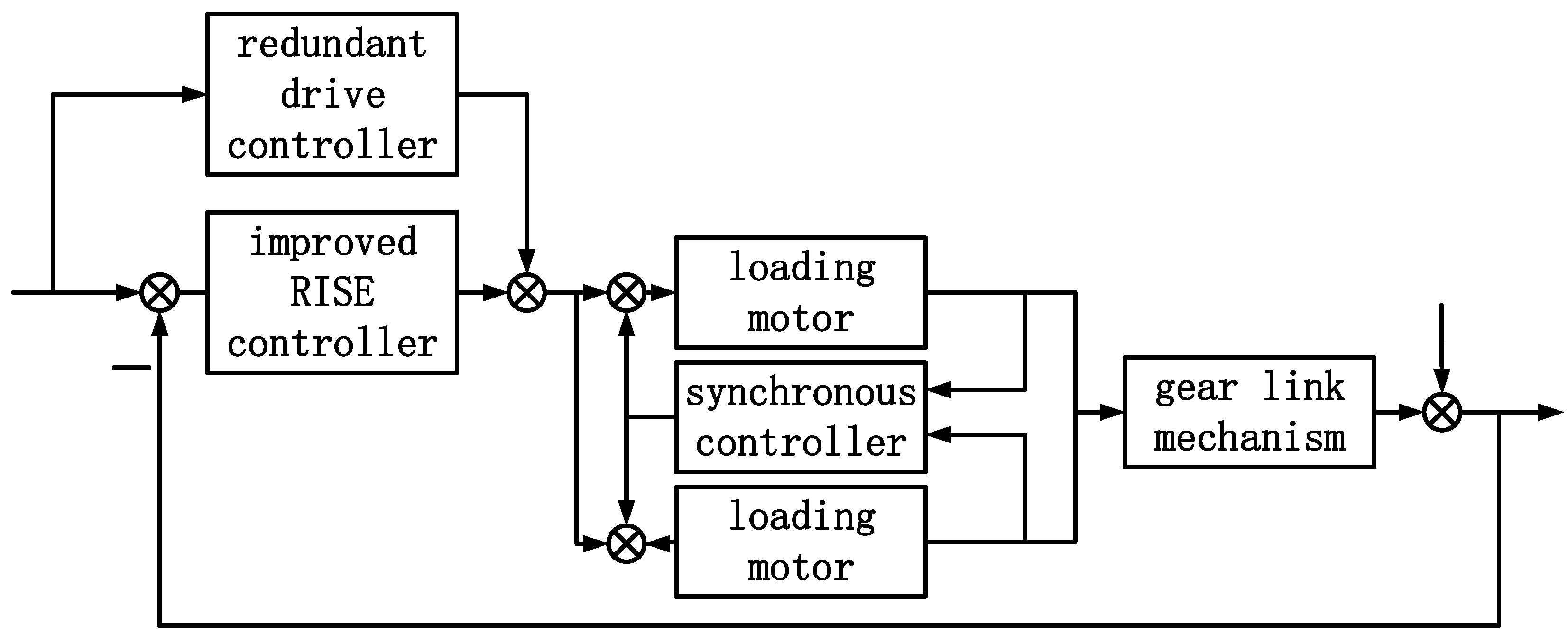
4. Control Strategy Design of Dual-Motor Load Simulator

Based on the mathematical modeling of the dual-motor load simulator, in order to improve the accuracy of the system loading torque and suppress backlash interference, this paper proposes a composite controller based on torque control backlash compensation speed synchronization. The overall control structure is shown in Figure 5. The torque control is realized by improving the RISE controller. On this basis, the backlash compensator based on the drive redundancy control method is used to eliminate backlash interference and further improve the output accuracy of the system. Finally, the torque controller and backlash compensator can be guaranteed to operate stably in the dual-motor system through the dual-motor synchronous controller.
Compared with traditional controllers, there are three innovations:
(1)
Aiming at the problem of system output torque control, the controller is designed based on the improved RISE control strategy. The RISE controller is improved by combining the dimension-matching criterion of the self-coupling PID and the adaptive symbolic integration, which simplifies the parameter-tuning process and improves the tracking effect.
(2)
Aiming at the problem of backlash interference, a backlash compensator is designed based on the dual-motor drive redundancy strategy. Based on the analysis of the generating link of the backlash, the system preset is used as the input of the compensator, and the backlash interference is compensated by changing the output direction of the dual motors in turn.
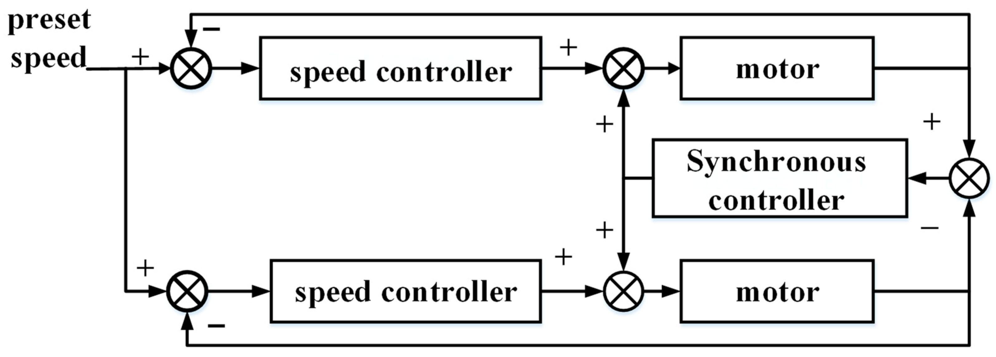
(3)
Aiming at the problem of asynchronous running speed of dual motors caused by the difference of dual-motor parameters, a synchronization controller is designed based on cross-coupling control to ensure the synchronous running of the dual-motor system. The tracking differentiator is used to eliminate noise and interference, and the improved RISE control strategy is combined to ensure the speed synchronization of the two motors in operation.
The preset value of the single-motor load simulator system is set as x r , the actual output value of the system is set as x , and the error expression of the system is defined as
e 1 = x r x
where x r is the preset value, x is the feedback value, and e 1 is the tracking error. Define the auxiliary error expression as
e 2 = e ˙ 1 + e 1 e n = e ˙ n 1 + e n 1 + e n 2
The RISE controller is defined as
u ( t ) = k e n + 0 t ( k α e n + β sgn ( e n ) ) d τ
where k , α , β are all positive scalars. The symbolic function sgn ( x ) expression is
sgn ( x ) = 1 x > 0 0 x = 0 1 x < 0
According to the above definition, the controller of the single-motor load simulator is designed, n is taken as 2, and the design controller input is
u ( t ) = k e 2 + 0 t ( k α e 2 + β sgn ( e 2 ) ) d τ
For RISE control, the following two innovations are proposed.
(1)
Based on the dimension-matching principle of self-coupling PID control, the paper improves it. In RISE control, parameters, k , α , β are independent parameters. There is no universal tuning method in parameter tuning. According to the physical attributes in the control link, each parameter can be regarded as a unified whole through the dimension-matching mechanism. It can not only simplify the parameter adjustment process, but also optimize the control effect by making use of the internal connection of each link [25]. References [26,27] proved through experiments that the improved control method of the dimension-matching criterion has better anti-interference and better control performance than the original algorithm.
Analyzing the physical significance of each link in RISE control:
In RISE control, both the actual output and the preset output are assumed to be generalized displacements with the dimensional attribute of generalized displacements.
  • k e 2 can be written to k e ˙ 1 + k e 1 . k e 1 is a generalized displacement error. Its dimension attribute is a generalized displacement, temporarily recorded as m . k e ˙ 1 is the differential of the generalized displacement, with the dimensional attribute of the generalized velocity, temporarily recorded as m / s .
  • 0 t ( k α e 2 ) d τ can be written to k e ˙ 1 d τ + k e 1 d τ . The dimension attribute of k e ˙ 1 d τ generalized displacement is temporarily recorded as m . k e 1 d τ has the dimension attribute of generalized displacement · second, temporarily recorded as m s .
  • 0 t β sgn ( e 2 ) d τ is dimensionless, considering that the symbolic integral functions in the controller can quickly make the error return to 0 through the symbolic function in case of small error, similar to the role of differential term in general control. Therefore, the dimensional attribute with generalized velocity is defined.
  • Introduce the speed factor (dimension is 1/s) into the RISE controller and rewrite the controller expression as follows
    u ( t ) = 3 z c 2 e 2 + z c 3 0 t e 2 d τ + z c 2 0 t sgn ( e 2 ) d τ
    In the improved formula, each part of the sum has the highest dimension attribute. It can be seen from reference [28] that this method has global stability in the third-order system when the speed factor is greater than 0.
(2)
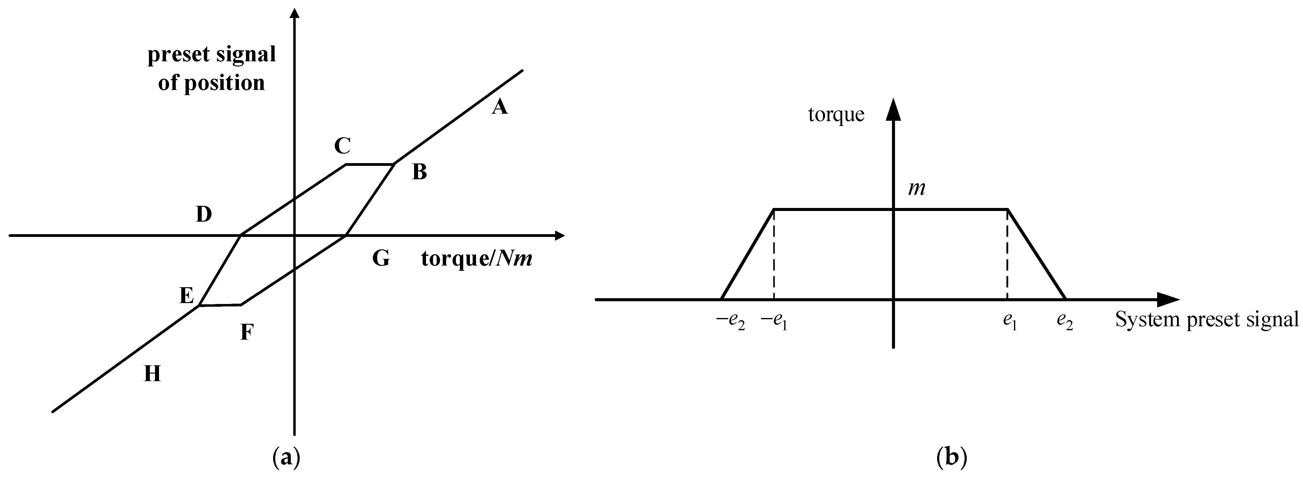
Variable Parameter Control Based on Sigmoid Function
In the initial stage of control, the error term and the symbolic integral term of the classical RISE controller act at the same time, causing the system error to oscillate at the beginning of control. An adaptive factor is introduced to improve the symbolic function, which weakens the role of the symbolic function in the initial stage of control. When the control error decreases, the symbolic function control role is increased to deal with external interference and small errors. The improved controller expression is
u ( t ) = 3 z c 2 e 2 + z c 3 0 t e 2 d τ + z c 2 0 t sgn ( e 2 ) d τ e β e 2
where β is a positive integer to adjust the effect of the sign integral at the initial stage of control.
According to the modeling analysis of the backlash dead zone, the backlash interference is maximum under the following two conditions when the system is running:
(1)
When the direction of the output torque of the system changes, the indirect contact surface of the gear will also change, and the backlash interference will be formed in the process of changing the contact surface.
(2)
When the system is started, the gear contact surface may change and the backlash interference may be formed.
The principle of eliminating backlash interference is to control the gear to be close to the contact surface as much as possible during steering and startup, so as to reduce the time for switching the contact surface. The drive redundancy method is based on this principle to eliminate the influence of backlash by applying opposite bias torque to two groups of motors with the same load in the backlash process. The principle of the drive redundancy backlash interference compensator is shown in Figure 6.
Take the system preset input as the input of backlash interference compensator. When the system is not in the starting or reversing state, that is, the system preset signal is greater than e 2 , the backlash compensator controls the two motors to output the same bias torque, that is, section AB of Figure 6a. At this time, the resultant torque is 0, without the backlash compensation effect, and the backlash compensator does not work.
When the preset torque enters the steering phase, that is e 1 ~ e 2 , e 2 ~ e 1 , Figure 6b, the controller controls one of the motors to output the reverse torque first, as shown in the BCF section of Figure 6a, and then the second motor to achieve torque steering, as shown in the BCD section of Figure 6a. During this period, during this period, the output torques of the two motors are in opposite directions, and the two gears seize the big gear to avoid the output dead zone caused by backlash interference during torque steering, so as to realize the compensation for backlash interference.
The range of action of the backlash is set as ( e 2 , e 2 ) , the range of action of the maximum bias force is set as ( e 1 , e 1 ) , and the mathematical description of the backlash compensation controller is set as follows:
f = 0 e > e 2 m e e 1 e 2 e 1 < e < e 2 m e e 2 e 1 e 2 < e < e 1 m e < e 1
Due to the dual-motor structure, on the one hand, due to the influence of parameters and armature voltage fluctuations, the speed of the dual motors is different. On the other hand, there must be a process of asynchronous speed between the two motors in the process of backlash compensation, so it is necessary to quickly restore the speed synchronization of the two motors after the completion of backlash compensation, otherwise the normal operation of the dual-motor system will be affected.
Cross-coupling control is selected as the synchronization control method of the dual motors. In terms of the synchronization index, since there are angular velocity sensors in the electric load simulator, the respective angular velocity of the two motors is selected as the index of speed synchronization control. The cross-coupling control structure is shown in Figure 7. After the speed difference of the motor, it is controlled by the speed synchronization controller. This method not only reduces the speed error between two motors, but Also, when one motor output torque is disturbed, it can be adjusted quickly to keep the two motors synchronized.
The speed synchronization controller is designed based on the improved RISE control. The RISE controller, which contains a symbolic function and higher derivative, is not suitable for motor speed control with large value, fast change, and easy disturbance. In view of this problem, two improvements are proposed for RISE control:
(1)
A tracking differentiator is added to track the motor speed signal as the input of the RISE controller. The tracking differentiator obtains the tracking signal and its derivative through the fastest synthesis function, which can effectively filter out noise and high-order interference. The mathematical expression of the tracking differentiator is
x 1 ( k + 1 ) = x 1 ( k ) + h * x 2 ( k ) x 2 ( k + 1 ) = x 2 ( k ) +        h * f h a n ( x 1 ( k ) v , x 2 ( k ) , r , h 0 )
The f h a n ( ) function is as follows:
f h a n ( x 1 ( k ) v , x 2 ( k ) , r , h 0 ) = d = r h 2 ; a 0 = h x 2 ; y = x 1 + a 0 a 1 = d 2 + 8 d y a 2 = a 0 + s i g n ( y ) ( a 1 d ) / 2 s y = [ s i g n ( y + d ) s i g n ( y d ) ] / 2 a = ( a 0 + y a 2 ) s y + a 2 s a = [ s i g n ( a + d ) s i g n ( a d ) ] / 2 f h a n = r [ a / d s i g n ( a ) ] s a r s i g n ( a )
(2)
The sign function in the RISE controller is replaced with the limiting function. Symbolic functions enable the controller to quickly adjust the output within small errors and ranges. The sign function is improved into a continuous limiting function, The output of sat (e2) will not have a sudden change, which is more conducive to speed synchronization control. The improved controller is
u ( t ) = k e 2 + 0 t ( k α e 2 + β s a t ( e 2 ) ) d τ

5. Results and Discussion
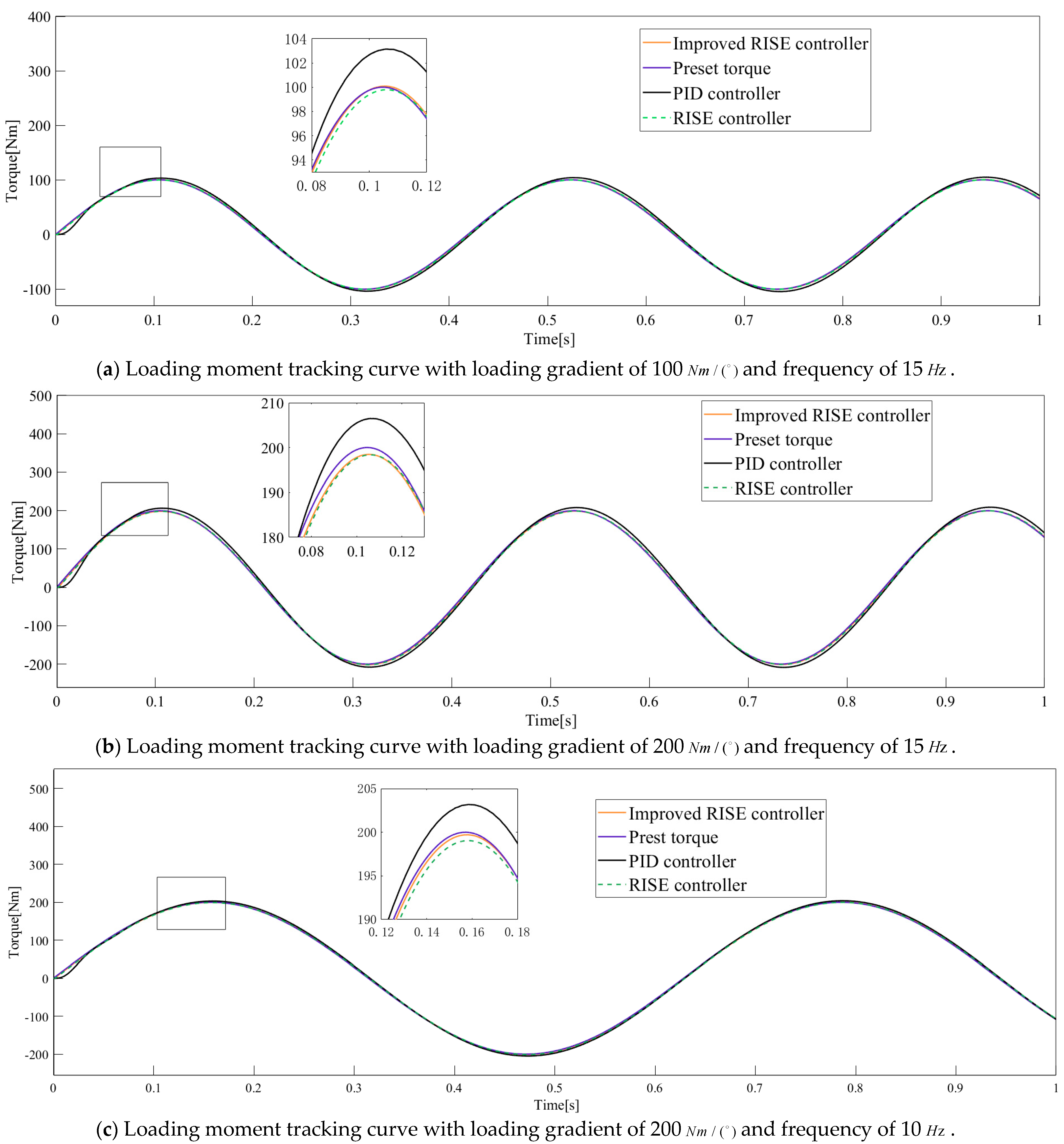
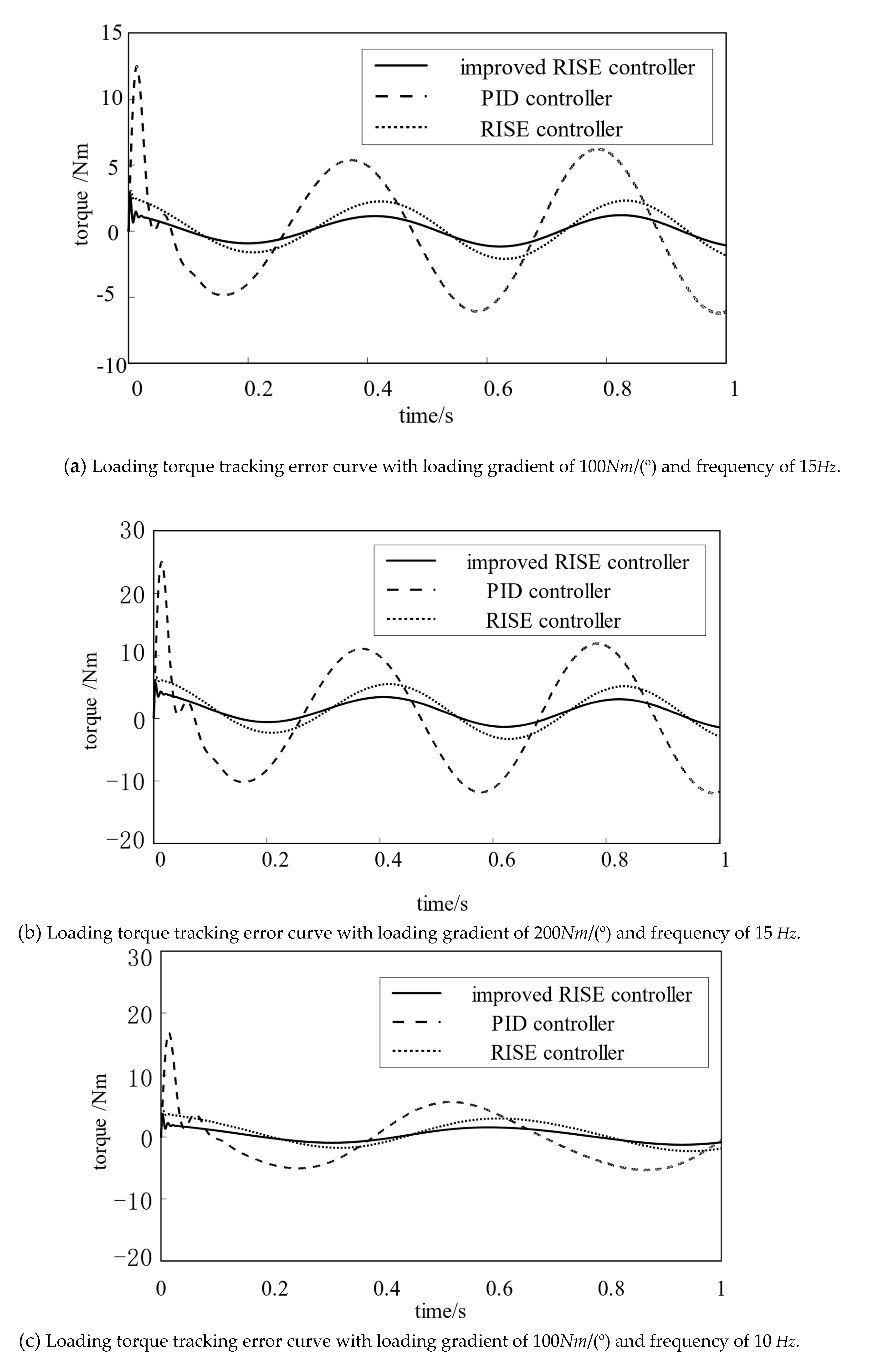
The electric load simulator model of double motors is established on the Matlab/Simulink platform, and the same parameters are used for double motors. The parameters are as follows: R = 4.32 , L = 0.005 , C e = 3.6 , J = 0.12 . The experiment is divided into three groups. The traditional PID controller, the RISE controller, and the improved RISE controller are used, respectively, to carry out the surplus force suppression experiment. The traditional PID control parameters are P = 100, D = 10, I = 2. The control parameters of RISE controller are 40, 5, and 5.
The experiment is divided into three groups: in the first group, the preset signal of the loading motor is sin ( 15 t ) and the loading gradient is 100 Nm/(°); in the second group, the second group preset signal is sin ( 15 t ) and the loading gradient is set to 200 Nm/(°); in the third group, the preset signal of the loading motor is sin ( 30 t ) and the loading gradient is 100 Nm/(°). The formula of the torque preset value is:
Torque preset value = preset signal × Loading gradient
The torque tracking effect and error in the experiment are shown in Figure 8 and Figure 9 and Table 1.
The following conclusions can be drawn from the analysis of Figure 9 and Table 1 of Figure 8:
(1)
Under the same loading frequency, the tracking error of the RISE controller is better by changing the loading gradient. When the loading frequency is 15Hz, the loading gradient is changed to 100 Nm/(°) and 200 Nm/(°), and the error of the improved RISE controller is 1.13% and 1.70%, which is far lower than the former two control methods. Under the conditions of 15Hz and 200 Nm/(°), the tracking error of the improved RISE controller is 72.5% and 44.0% lower than that of PID controller and RISE controller, respectively.
(2)
Change the frequency of the preset signalunder the same loading gradient condition 200 Nm/(°). The tracking error effect of the improved RISE controller is still the best, and the error at 10:00 is only 0.77%. Compared with the PID controller and RISE controller, the tracking error is reduced by 72.8% and 47.3%, respectively, and the effect is significantly improved. When the system is started, the improved RISE controller has no error peak, which proves that the adaptive integral factor plays a role in improving the accuracy.
The experimental results show that the improved RISE controller can effectively improve the control effect and achieve the torque control requirements in the dual-motor load simulator.

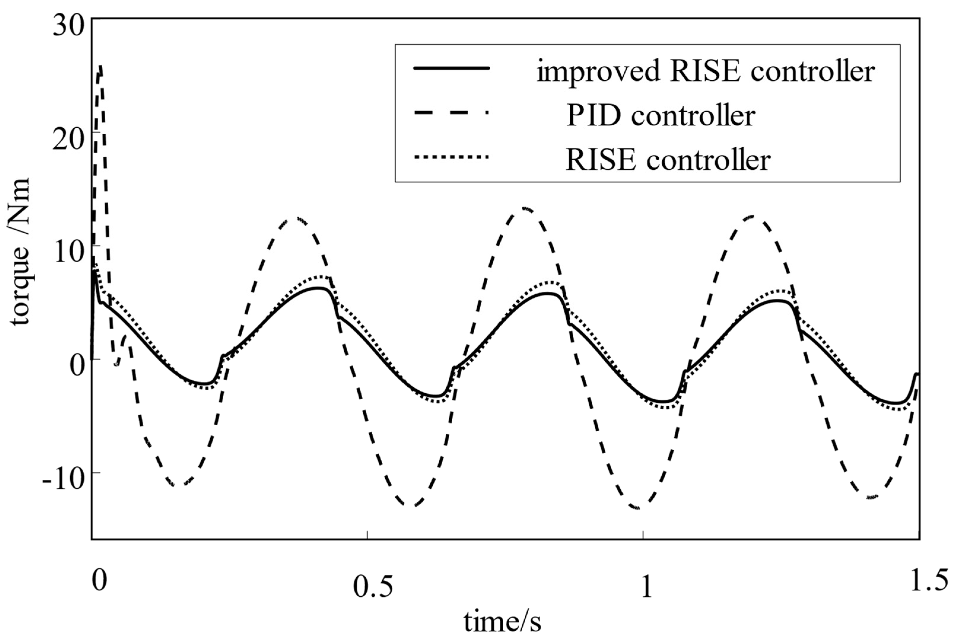
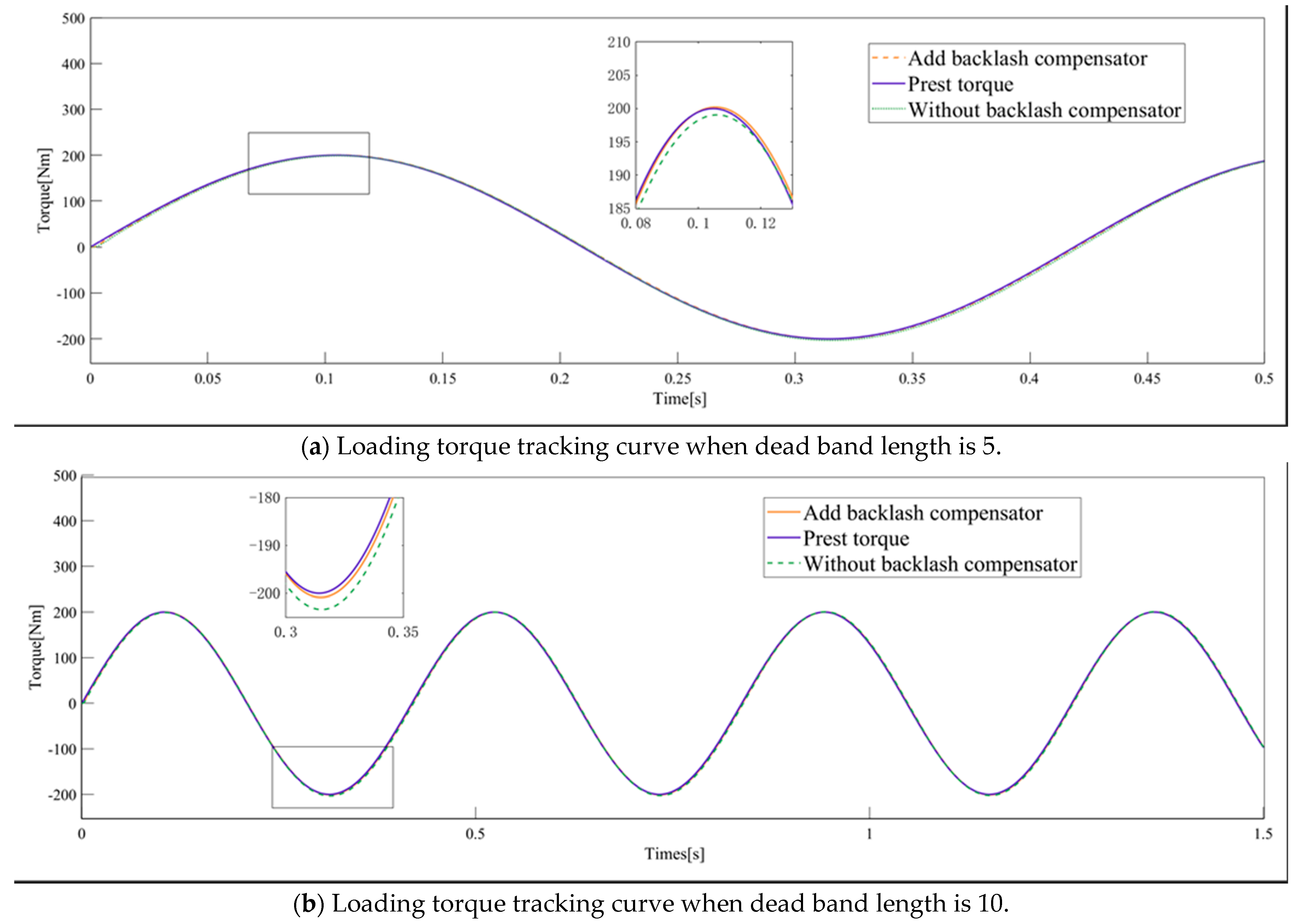
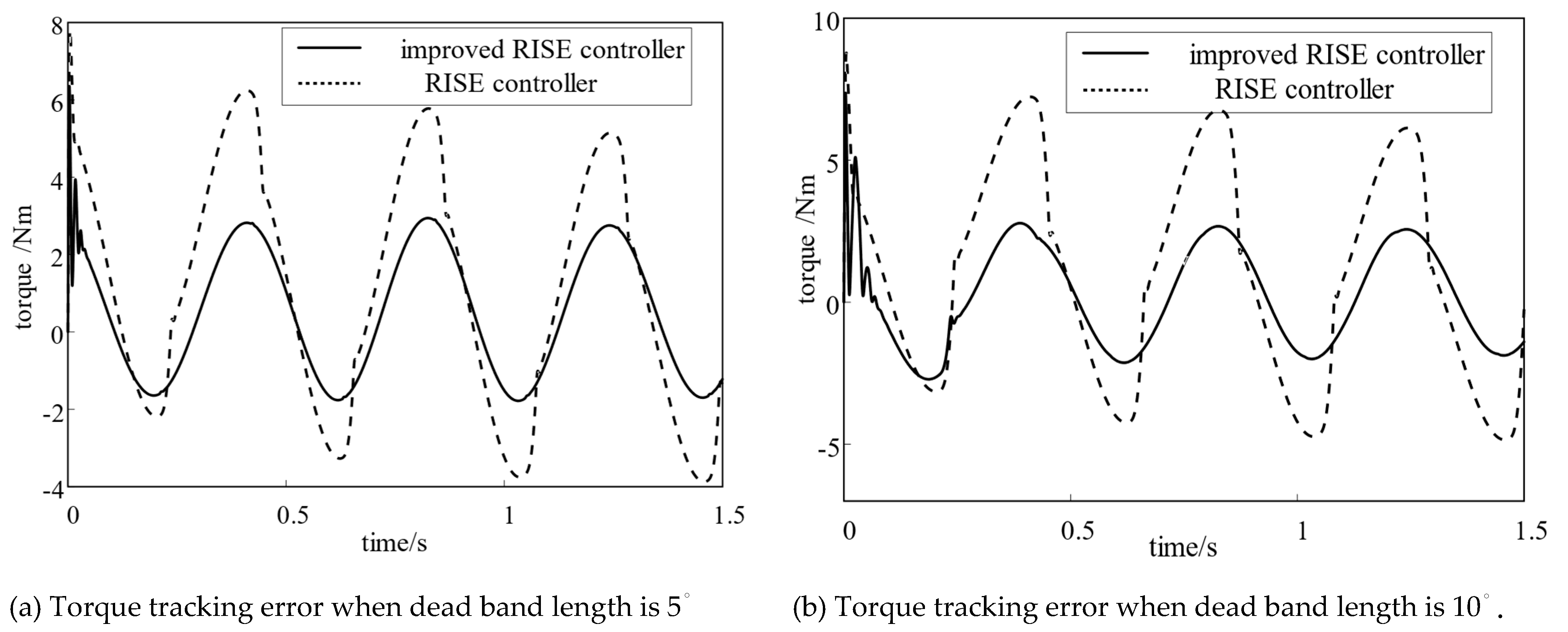
Influence of Backlash and Dual Motor Parameters on Control Error

In this experiment, different parameters are used for dual motors. The parameters of motor 1 remain unchanged, and are still R 1 = 4.32 , L 1 = 0.005 , C e 1 = 3.6 , and J 1 = 0.12 . The motor 2 parameters are set as R 2 = 4.4 , L 2 = 0.005 , C e 2 = 3.6 , and J 2 = 0.08 . A backlash compensator and a speed synchronization controller are introduced. Set the preset value of the loading motor as sin ( 15 t ) , set the loading gradient as 200 Nm/(°), and add the backlash interference with a dead zone length of 5°. The preset value of the loading motor is set to sin ( 15 t ) , and the dead band length of 5 is added, respectively, when the loading gradient is 200 Nm/(°). The backlash interference of the tracking error of the system is shown in Figure 10 and Table 2.
It can be seen from the comprehensive analysis in Figure 10 and Table 2 that the introduction of backlash interference and the difference between the parameters of dual motors will lead to an increase in the error of the system during operation to the effect of backlash interference. The error is the largest when the output torque changes direction and the system starts, which is consistent with the analysis results of the backlash in the previous article.
The following conclusions can be drawn from the analysis of Figure 11 and Figure 12 and Table 3 and Table 4:
(1)
After compensating the system backlash interference, the system loading torque tracking error decreases by 52% and 57%. It is proved that the offset force compensation method can effectively eliminate the influence of backlash on tracking error in dual-motor system. The offset force compensation has an excellent inhibition effect for different backlash.
(2)
Under different backlash conditions, the cross-coupling control strategy improved by tracking differentiator can keep the speed synchronization of the two motors. According to the tracking error curve, the response time of the system is accelerated, and the speed error is reduced by 62.1% and 61.2%, which proves that the improved algorithm can effectively control the smooth synchronous operation of dual motors.
(3)
According to the analysis in Table 1 and Table 4, the proposed composite control strategy of the loading torque controller backlash compensator speed synchronization controller can achieve high-precision output of system loading torque under the conditions of redundant torque disturbance, backlash dead zone disturbance, and dual-motor parameter difference in the aircraft steering gear electric load simulator with dual-motor loading structure.
At this time, the speed error comparison of dual motors is shown in Table 4.

6. Conclusions

(1)
The electric load simulator of an aircraft steering gear loaded with two motors is designed, which can output the loading torque through the cooperation of two motors. A compound control strategy consisting of torque control feedback, backlash compensation feedforward, and cross-coupling speed synchronization control of dual motors is proposed.
(2)
Compared with the conventional PID controller, the proposed compound control strategy can achieve the accurate output of analog torque, and the error is only 1.13% when there is only the disturbance of redundant torque. The tracking error is only 1.54% under the conditions of redundant torque, backlash interference, and different parameters of dual motors. The experimental results show the effectiveness of the proposed control strategy.
In the subsequent work, the influence of the redundant torque caused by the more complex steering gear signal on the load simulator will be studied, and the redundant torque signal will be classified and summarized on the mathematical level. The difficulty of the dual-motor system is the bandwidth of the system under different motor parameters, which is what we need to study later.

Author Contributions

Conceptualization, X.L. and J.L.; methodology, J.L.; software, J.L.; validation, J.L.; formal analysis, J.L.; investigation, J.L.; resources, J.L.; data curation, J.L.; writing—original draft preparation, J.L.; writing—review and editing, X.L. and J.L.; visualization, J.L.; supervision, J.L.; project administration, J.L.; funding acquisition, X.L. All authors have read and agreed to the published version of the manuscript.

Funding

This research received no external funding.

Data Availability Statement

Not applicable.

Conflicts of Interest

The authors declare no conflict of interest. The funders had no role in the design of the study; in the collection, analyses, or interpretation of data; in the writing of the manuscript; or in the decision to publish the results.

References

  1. Zheng, Y.B.; Yu, Z.L.; Ma, G.Q. Model Error Analysis of Load Simulator System. J. Phys. Conf. Ser. 2020, 1676, 1–11. [Google Scholar] [CrossRef]
  2. Yang, B.; Bao, R.; Han, H. Robust hybrid control based on PD and novel CMAC with improved architecture and learning scheme for electric load simulator. IEEE Trans. Ind. Electron. 2014, 61, 5271–5279. [Google Scholar] [CrossRef]
  3. Li, C.G.; Jin, H.T.; Jiao, Z.X. Mechanism and suppression of extraneous torque of motor driver load simulator. J. Beijing Univ. Aeronaut. Astronaut. 2006, 32, 204–208. [Google Scholar]
  4. Jiao, Z.X.; Hua, Q.; Wang, X.D.; Zhang, S.P. Estimation for performance of load simulator. Chin. J. Mech. Eng. 2002, 38, 26–30. [Google Scholar] [CrossRef]
  5. Gao, F.; Lin, H.; Du, X.G. Research of a dynamic measuring method of moment of inertia and an elimination method of plus torque in electric loading system. Comput. Meas. Control 2005, 13, 635–637. [Google Scholar]
  6. Lyu, S.S.; Lin, H. Composite control for electric dynamic loading system based on fractional order iterative learning. J. Beijing Univ. Aeronaut. Astronaut. 2016, 42, 1944. [Google Scholar]
  7. Bo, Y.; Fuhuang, L.; Meng, Z. A Loading Control Strategy for Electric Load Simulator Based on New Mapping Approach and Fuzzy Inference in Cerebellar Model Articulation Controller. Meas. Control 2019, 52, 131–144. [Google Scholar]
  8. Gu, N.; Yang, B. Semi-fuzzy CMAC and PD hybrid controller with compressed memory and semi-regularization for electric load simulator. IET Control Theory Appl. 2019, 13, 3065–3074. [Google Scholar] [CrossRef]
  9. Zheng, D.K.; Xu, H.G. Torque tracking experiment of a friction based electro-hydraulic load simulator. J. of Harbin Inst. of Technol. Jan. 2017, 49, 66–71. [Google Scholar]
  10. Dai, M.G.; Qi, R. Backstepping sliding mode control of electric dynamic load simulator based on extended state observer. Acta Aeronaut. ET Astronaut. Sin. 2020, 41, 280–290. [Google Scholar]
  11. Wang, L.S.; Wang, M.Y.; Guo, B. A high frequency loading control strategy based on proportional resonant control and stability analysis for electric load simulators. Proc. CSEE 2018, 38, 4262–4270. [Google Scholar]
  12. Liu, X.L.; Jiang, M.X. A study on double loop composite control based on WOA for an aircraft rudder electric loading system. J. Vib. Shock. 2021, 40, 246–253, 289. [Google Scholar]
  13. Liu, H.; Liu, H.; Shan, X. Linear active disturbance rejection control with torque compensation for electric load simulator. J. Power Electron. 2021, 21, 195–203. [Google Scholar] [CrossRef]
  14. Niu, G.C.; Wang, W.; Zong, G.H. Composite control for electric load simulator based on iterative learning. Control Theory Appl. 2014, 31, 1740–1747. [Google Scholar]
  15. Dai, M.G.; Qi, R. Composite iterative learning control for electric dynamic loading system with control time delay. J. Beijing Univ. Aeronaut. Astronaut. 2020, 46, 340–349. [Google Scholar]
  16. Li, C.C.; Wang, G.L.; Pan, X.D.; Li, Y.F. Research on parameter identification method of friction model for electric load simulator. J. Vib. Meas. Diagn. 2020, 40, 519–525, 626. [Google Scholar]
  17. Pan, W.D.; Fan, Y.X.; Lei, J.J.; Dawei, C.A.O.; Pengcheng, L.U.; Zhiwei, X.U. Effect of friction on electric linear load simulator and research on friction suppression. Acta Armamentarii 2019, 40, 2050–2059. [Google Scholar]
  18. Patre, P.M.; Mackunis, W.; Makkar, C.; Dixon, W.E. Asymptotic tracking for systems with structured and unstructured uncertainties. IEEE Trans. Control Syst. Technol. 2008, 16, 373–379. [Google Scholar] [CrossRef]
  19. Shin, J.; Kim, H.J.; Kim, Y.; Dixon, W.E. Autonomous flight of the rotorcraft-based UAV using RISE feedback and NN feedforward terms. IEEE Trans. Control Syst. Technol. 2012, 20, 1392–1399. [Google Scholar] [CrossRef] [Green Version]
  20. Fishcher, N.; Bhasin, S.; Dixon, W.E. Nonlinear control of an autonomous underwater vehicle: A RISE-based approach. In Proceedings of the 2011 American Control Conference, San Francisco, CA, USA, 29 June–1 July 2011; pp. 3972–3977. [Google Scholar]
  21. Arcolezi, H.H.; Nunes, W.R.; de Araujo, R.A.; Cerna, S.; Sanches, M.A.; Teixeira, M.C.; de Carvalho, A.A. RISE controller tuning and system identification through machine learning for human lower limb rehabilitation via neuromuscular electrical stimulation. Eng. Appl. Artif. Intell. 2021, 102, 13. [Google Scholar] [CrossRef]
  22. Hfaiedh, A.; Chemori, A.; Abdelkrim, A. Observer-based robust integral of the sign of the error control of class I of underactuated mechanical systems: Theory and real-time experiments. Trans. Inst. Meas. Control 2022, 44, 339–352. [Google Scholar] [CrossRef]
  23. Lee, D.; Byun, J.; Kim, H.J. RISE-based trajectory tracking control of an aerial manipulator under uncertainty. IEEE Control Syst. Lett. 2022, 6, 3379–3384. [Google Scholar] [CrossRef]
  24. Meng, Q.; Liu, N.; Shao, X.; Yang, W. Desired Compensation RISE Attitude Control for a Quadrotor UAV with Adaptive Gain Adjustment. Electron. Opt. Control 2020, 27, 25–29. [Google Scholar]
  25. Zhao, G.F.; Fan, W.D.; Chen, Q.W.; Hu, W.L. A survey on backlash nonlinearity. Acta Armamentarii 2006, 6, 1072–1080. [Google Scholar]
  26. Zeng, Z.Z.; Liu, W.J. Self-coupling PID controllers. Acta Autom. Sin. 2021, 47, 404–422. [Google Scholar]
  27. Zeng, Z.Z.; Chen, Z.Y. On control theory of PID and auto-coupling PID. Control. Theory Appl. 2020, 37, 2654–2662. [Google Scholar]
  28. Su, J.; Zeng, Z.H. Auto-coupling pid control method for nonlinear time varying systems. Control. Theory Appl. 2022, 39, 299–306. [Google Scholar]
Figure 1. Single-motor electric load simulator system structure.
Wevj 14 00028 g001
Figure 2. Dual-motor electric load simulator system structure.
Wevj 14 00028 g002
Figure 3. Dual-motor drive structure.
Wevj 14 00028 g003
Figure 4. System structure diagram.
Wevj 14 00028 g004
Figure 5. System control structure diagram.
Wevj 14 00028 g005
Figure 6. Schematic diagram of drive redundancy control. (a) Motor torque diagram; (b) Schematic diagram of offset force.
Wevj 14 00028 g006
Figure 7. Cross-coupling structure diagram.
Wevj 14 00028 g007
Figure 8. Command torque tracking effect.
Wevj 14 00028 g008
Figure 9. Tracking error of command torque.
Wevj 14 00028 g009
Figure 10. Tracking error of different backlash.
Wevj 14 00028 g010
Figure 11. Loading torque tracking curve after adding backlash compensator and speed synchronization controller.
Wevj 14 00028 g011
Figure 12. Loading torque tracking error curve after adding backlash compensator and speed synchronization controller.
Wevj 14 00028 g012
Table 1. Torque loading data.
Control MethodFrequency/(Hz)Loading Gradient/(N·m/(°))Amplitude/(N·m)Error of Amplitude/%
PID controller15100105.375.37
15200211.635.57
10200206.662.83
RISE controller1510097.692.31
15200194.532.73
10200197.061.46
Improved RISE controller1510098.861.13
15200196.941.53
10200198.460.77
Table 2. Tracking error of different backlash.
Controller MethodError of Amplitude/(N·m)Error of Amplitude/%Error of Amplitude/(N·m)
PID controller13.216.6113.21
RISE controller7.213.617.21
Improved RISE controller6.243.126.24
Table 3. Tracking error of clearance compensation.
Control MethodLength of BacklashError of Amplitude/(N·m)Error of Amplitude/%
Uncompensated clearance, asynchronous speed03.401.70
56.233.12
107.243.62
Compensation clearance, synchronous speed02.931.46
52.941.47
103.081.54
Table 4. Velocity error of different backlash.
Control MethodLength of BacklashSpeed/(m/s)Error of Speed/%
No speed synchronization5183.72.96
10182.32.97
Speed synchronization5701.12
1070.71.15
Disclaimer/Publisher’s Note: The statements, opinions and data contained in all publications are solely those of the individual author(s) and contributor(s) and not of MDPI and/or the editor(s). MDPI and/or the editor(s) disclaim responsibility for any injury to people or property resulting from any ideas, methods, instructions or products referred to in the content.

