1. Introduction
Recently, with the introduction of various agricultural machinery subsidy policies, there has been an increase in the use of tractors as the main power machinery for agricultural production operations. The national “14th Five-Year Plan and 2035 Long-term Goals” proposed goals regarding a carbon emission peak in 2030 and carbon neutrality in 2060. At this stage, agricultural machinery mainly uses diesel engines as the main power source, which consume a significant amount of fuel during operation and result in greenhouse gas emissions [
1]. Under the double pressure of the global energy crisis and environmental pollution, it is particularly important to design and develop energy-saving and environmentally friendly agricultural machinery vehicles [
2,
3,
4]. With the improvements in hybrid vehicle technology, hybrid tractors have been developed [
5]. Hybrid tractors are energy-saving and environmentally friendly agricultural machinery vehicles that have the advantages of both traditionally fueled tractors and electric tractors [
6,
7,
8]. The energy conversion of a series hybrid tractor is repeated during operation, which results in low energy utilization efficiency. Meanwhile, parallel hybrid tractors can be powered directly by diesel engines or electric motors. It has no secondary energy conversion and realizes high energy utilization efficiency. Therefore, based on the topology of a parallel diesel-electric hybrid tractor, this study develops an energy-saving control strategy to improve the energy utilization efficiency of the entire machinery.
Using the energy-saving control strategy as the core control strategy of a hybrid tractor directly affects the performance of a hybrid tractor. Currently, energy-saving control strategies can be mainly divided into two categories: rule-based control strategies and optimization-based control strategies [
9,
10].
Rule-based control strategies are inexpensive to develop and simple to implement, and they are widely used in various types of hybrid vehicles. Luo et al. [
11] proposed a fuzzy reasoning energy management strategy for a series of diesel-electric hybrid tractors. The engine demand power is determined according to the self-set fuzzy reasoning rule table. The corresponding results demonstrate that the fuel economy is improved by 20.92% compared with the power following control strategy. Xu et al. [
12] proposed a predefined energy management strategy for extended-range electric tractors; they indicated that the fuel consumption was reduced by 34.22% in the continuous transition operation mode. Based on series hybrid tractors, Fang et al. [
13] proposed a fuzzy control energy management strategy that differentiated between electric vehicles and electric tractors. Their results showed that the battery of the state of charge (SOC) curve shows the slowest change when the fuzzy control energy management strategy is adopted. However, rule-based control strategies are certain and according to the designer’s experience, they do not exhibit good adaptability to working conditions [
14].
Optimization-based control strategies are solved by minimizing or maximizing a cost function, which is generally a measure of the control target. Lee et al. [
15] established a power shunt ratio strategy based on a drivetrain simulation model. The power allocation strategy of a hybrid electric tractor was optimized using a deterministic dynamic programming algorithm. Simulation results show that the proposed control strategy can reduce the fuel consumption of a hybrid electric tractor. Spano et al. [
16] proposed a multi-objective particle swarm optimization algorithm to determine the optimal power system layout of parallel P2 hybrid electric vehicles, aiming to maximize fuel economy and minimize production costs. The results showed that the control algorithm can improve the fuel economy of HEV and reduce HEV production costs. Qian et al. [
17] proposed a calculation method based on the fuzzy PID torque recognition coefficient K. Subsequently, they used the particle swarm-ant colony combination optimization algorithm to optimize the key control parameters in the control strategy. Their results indicated that the fuel consumption and emissions are reduced by ensuring the dynamics of the entire vehicle. However, the solution of deterministic dynamic programming algorithms requires extracting control rules, which is computationally intensive and time-consuming. The particle swarm optimization algorithm has strong global search ability and is a simple algorithm, but it has poor local search ability. Meanwhile, the control strategy of particle swarm-ant colony combination optimization algorithm is more complicated. Recently, energy-saving control strategies based on instantaneous optimization have become a research hotspot in the vehicle control field, owing to their advantages of fast calculation speed, good control effect, smaller calculation amount than dynamic programming algorithms, and simple control algorithms.
In this study, a diesel-electric parallel hybrid tractor is considered as the research object. Meanwhile, an energy-saving control strategy based on instantaneous optimization of the required torque is proposed [
18,
19,
20,
21,
22,
23]. By optimizing the torque of both the diesel engine and motor, the required torque of the entire machine can be distributed in real time, which reduces the equivalent fuel consumption of the entire machine while ensuring power stability. First, the topology and performance parameters of the hybrid tractor are introduced; then, the main components are simulated and modeled [
24,
25]. Based on the entire machine model, an energy-saving control strategy based on instantaneous optimization was designed. The simulation results were analyzed and compared with the power-following energy-saving control strategy. Finally, the conclusions of this study are presented.
2. Tractor Topology and Main Parameters
2.1. Subsection Model of Hybrid Tractor Drivetraino
Figure 1 shows the topology of a parallel diesel–electric hybrid tractor, which has two drive systems, namely a diesel engine and an electric motor. The diesel engine is the main power source, and the electric motor is the auxiliary power source [
26]. The engine and motor output torques are transmitted to the transmission input shaft through the torque coupler, followed by the transmission output power. It is used as the power input of the central transmission device and power take-off (PTO) shaft. The vehicle controller and power battery, low-voltage battery, diesel engine, clutch, drive motor, transmission, AC/DC module, and DC/DC module are connected through the CAN bus. According to the total power demand of the entire machine and SOC value of the power battery, the torques of the diesel engine and motor are dynamically distributed according to the control strategy and algorithm of the entire machine. Accordingly, the tractor can achieve the best power and economic performance.
2.2. Subsection Model of Hybrid Tractor Drivetraino
In this study, the energy-saving control strategy of a 220 hp hybrid tractors is investigated. The main components of the hybrid tractor were selected according to its working conditions [
27]. The specific parameters are listed in
Table 1.
2.3. Determination of Theoretical Speed and Transmission Ratio
The design of the transmission gear ratio is based on the working characteristics of the tractor, speed range of various working conditions of the current tractor, and the output characteristics of the hybrid tractor coupling system. Subsequently, the main reducer and gearbox transmission ratio, and its theoretical speeds are matched and calculated [
28,
29].
When rotary tillage is performed, the traveling speed of the tractor is 4–5 km/h, and the theoretical value of the PTO speed is 540 rpm. From this, the speed ratio of the main reducer is determined as
i0, which is taken as 19.10. Seven forward gears are designed, including three transport gears, two working gears, and two amble gears [
30,
31]. The corresponding transmission ratio increases sequentially, while the theoretical speed decreases sequentially. The specific parameters used are listed in
Table 2.
3. Hybrid Tractor Model Building
Based on the topology of the hybrid tractor, its main components were modelled, including the transmission system, rotary tillage unit dynamic, plowing unit dynamic, tire, motor, diesel engine, power battery model. Subsequently, the simulation model of the machine was built.
3.1. Model of Hybrid Tractor Drivetraino
The required torque of the hybrid tractors provided by the motor and diesel engine. The required torque of the entire machine is obtained at the input end of the torque coupler, which can be expressed as follows:
where
Tm and
Te are the motor and diesel engine torques, respectively.
ηm and
ηe represent the working efficiencies of the motor and diesel engine, respectively.
Treq is the torque required for the torque coupler input.
According to the tractor working speed and parameters of each component used to calculate the power source speed, this study considers the diesel engine speed as the power source speed, which can be expressed as follows:
where
it and
i0 are the transmission and main reducer speed ratios, respectively.
ntire and
ne are the drive and diesel engine speeds, respectively.
v is the speed of the hybrid tractor during operation.
r is the driving wheel radius of the hybrid tractor.
3.2. Dyanmic Model of Rotary Tillage Unit
The power balance relationship characterizing the working time group of the hybrid tractor traction rotary cultivator is formulated as follows:
where
Pdrive and
Pr are the tractor travel power and rotary cultivator power consumptions, respectively.
ηr, ηzj, ηb, and
ηo represent the rotary tillage unit mechanical transmission efficiency, main reducer transmission efficiency, transmission efficiency, and torque-coupler efficiency, respectively.
Pc, Pth, Pa, and
Ph are the cutting power consumption, throwing earth power consumption, rotary cultivator forward power consumption and power required to overcome the soil horizontal reaction forces, respectively.
m is the tractor mass.
f is the rolling resistance coefficient.
δ is the mass conversion of the factor. α is the tilt of the ground.
Cd and
A are the tractor drag coefficient and windward area, respectively.
When the tractor is operating at a low speed, the influence of air resistance and acceleration resistance on the tractor can be ignored [
28].
The hybrid tractor is equipped with a double-acting clutch, which can realize independent control of the PTO power [
29]. The relationship formula of the rotary tillage operation timing group is as follows:
where
PPTO,
TPTO, and
nPTO are the power, torque, and speed of PTO, respectively.
vr is the forward speed of the rotary cultivator.
3.3. Dyanmic Model of Plowing Unit
When the tractor is working, its driving force must overcome the rolling resistance and other driving resistances before it can be operated. The balance between the driving force
FTN and various resistances when the tractor is operating is formulated as follows:
where
Fg,
Ff,
Fp,
FAf, and
Fi are the tillage, rolling, slope, air, and acceleration resistances, respectively.
FTN is the driving force.
When the tractor is operating at a low speed, the influence of air and acceleration resistances on the tractor can be ignored.
Under normal circumstances, the tractor drive force
FTN is primarily determined by the tillage resistance
Fg when the supporting agricultural tools are working. The calculation formula is stated as follows:
where
Z denotes the number of plowshares.
bl and
hk represent the individual plow width and depth, respectively.
k is the soil specific resistance coefficient.
The power demand at the input end of the torque coupler when the hybrid tractor pulls the plow unit can be expressed as follows:
3.4. Tire Model
The Duggof model belongs to the theoretical model and is suitable for the studying vehicle dynamics control algorithms. Therefore, the Duggof tire model is used to calculate the driving force of the driving wheel [
32], which can be expressed as follows:
where
Fq and
Fz are the driving and loading forces of the drive wheel, respectively.
φ and
ζ represent the slip rate of the corresponding drive wheel and adhesion factor of the corresponding drive wheel, respectively.
c is the horizontal distance of the hitch traction point from the center of the rear wheel.
3.5. Motor Model
A permanent magnet synchronous motor with superior performance is selected as the electric drive system of the tractor, which can operate not only in the forward direction, but also in the reverse direction. Moreover, it has the working characteristics of low-speed constant torque and high-speed constant power. The formula characterizing the relationship between the power, speed, and torque is stated as follows:
where
nm is the speed of the motor.
The motor model is established via a numerical model method, and the relationship between motor system efficiency, torque, and speed are obtained via the spline interpolation method based on experimental motor efficiency experimental data. The relationship is determined and unique, which is suitable for the studied control strategies. The numerical model of motor efficiency is shown in
Figure 2.
3.6. Diesel Engine Model
The diesel engine of the corresponding power is selected according to the use conditions of the hybrid tractor considering only the input and output parameters of the engine. The formula characterizing their relationship is stated as follows:
where
ne denotes the speed of the diesel engine.
Diesel engine modeling methods are mainly divided into two types: theoretical modeling and numerical modeling methods. The theoretical modeling method is based on the structural parameters of the engine, using thermodynamic theory, combustion theory, fluid mechanics, and heat transfer theory to establish a mathematical model of the engine working process. The numerical modeling method tests the load characteristics and speed characteristic curves of the engine by building an experimental bench of the engine and then constructing a numerical model by interpolation fitting. This study mainly uses the engine output characteristics to study the drive system of the whole machine, and only considers the relationship between the input and output parameters of the engine. Therefore, the method of measured modeling is adopted. On the basis of the engine steady-state test data, the number table or formula is used to fit to obtain an accurate and simple engine numerical model [
33], as shown in
Figure 3.
3.7. Power Battery Model
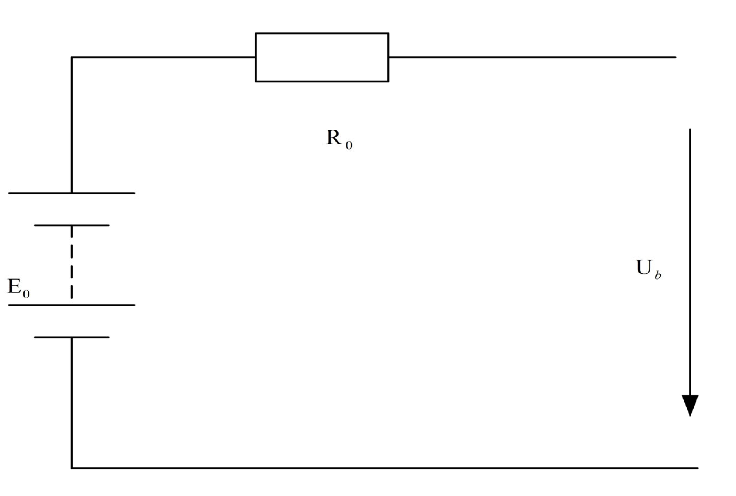
The power battery model describes the external characteristics of the power battery during operation, and most of the equivalent circuit models are currently used. Because the model has good applicability to various working states of power batteries, the equation of state of the model can be derived.
Therefore, the equivalent internal resistance model in the equivalent circuit model is used here. The power battery is equivalent to an ideal voltage source and a circuit model with a resistor connected in series. The mathematical equations are simple and easy to calculate and model, as shown in
Figure 4.
According to Ohm’s law, the voltage characteristic equation of a power battery is stated as follows:
where
Ub and
E0 are the power battery output voltage and terminal voltage, respectively.
Ib and
R0 represent the output current and internal resistance of the power battery, respectively.
Ignoring the influence of the internal resistance and discharge factors of the power battery on the electromotive force
E0 and setting it as a constant, the output power equation of the power battery can be stated as follows:
The charge and discharge power
Pbat(
t) of the battery is positive when discharged and negative when charging. This parameter is determined as follows:
where
ηbat is the battery charging and discharging efficiency.
The ampere-hour integral method is used to calculate the change in the SOC value of the power battery, which is formulated as follows:
where
Qb denotes the rated power battery capacity.
SOC0 represents the initial the state of charge value.
3.8. Power Battery Model
Based on the characteristics of the hybrid tractor transmission system, the simulation model of the entire machine is built using MATLAB. A simplified diagram of the entire machine model is shown in
Figure 5. The simulation model includes the dynamic model of the unit (rotary tillage and plowing), motor model, diesel engine model, transmission system model, battery model, and tire model.
FTN and
v are the resistance and travel speed of the tractor, respectively, which are determined based on the operating conditions of the tractor and are the output parameters of the dynamic model of the unit. Drivetrain model output torque and speed (
Treq and
nreq) at the input end of the torque coupler. The motor and diesel engine models receive the instructions (
Tmreq,
nmreq,
Tereq, and
nereq).
where
Tmreq and
Tereq are the torques required for the motor and diesel engine, respectively, at the input of the torque coupler.
Finally, the diesel engine and motor work according to the command and output the corresponding torque and speed. Through the drivetrain model, the power is transmitted to the tire model to ensure the normal operation of the whole machine.
4. Energy Saving Control Strategy Design
Based on the entire machine model, two energy-saving control strategies (based on instantaneous optimization and power follower) were designed. The design process of an energy-saving control strategy based on instantaneous optimization is introduced in detail, while that of a comparative control strategy (power-following) is briefly introduced.
4.1. Energy-Saving Control Strategy Based on Instantaneous Optimization
First, according to the topological structure and main component model of hybrid electric tractor, an energy-saving control optimization model of the entire machine is designed. Then, the optimization solution is carried out according to the instantaneous optimization algorithm. Finally, the solution flow is discussed in detail.
4.1.1. Optimization Model of Energy-Saving Control Strategy
A hybrid tractor has two energy sources, electric power and fuel. To unify the energy, the equivalent fuel consumption is used for the evaluation. The goal of energy management is to minimize the equivalent fuel consumption by optimizing and rationalizing the operating state between the diesel engine and motor. The equivalent fuel consumption in the operation process of the hybrid electric tractor, namely, the objective function, can be expressed as follows:
where
Qc(t) and
Qf(
t) are the equivalent fuel consumption and instantaneous fuel consumption, respectively.
tf represents the terminal moment.
je and
jm are the prices per liter of oil and per kWh of electricity, respectively.
fe is engine fuel consumption at that moment.
According to the calculation of the battery SOC value using Equation (18), the system state equation can be obtained as follows:
The control variables of the system are Te(t) of the diesel engine and Tm(t) of the motor torque. The relationship between them and the required torque is introduced based on Equation (1).
Because the working capacity of each component is limited by realistic conditions, the system must satisfy the following constraints:
where
Tmmin and
Tmmax are the minimum and maximum torques of the motor, respectively.
Temin and
Temax are the minimum and maximum torque of the diesel engine, respectively.
SOCmin and
SOCmax represent the minimum and maximum values allowed by the SOC value of the power battery, respectively.
Equation (22) constitutes the permissive reach of the control variables.
4.1.2. Establish the Optimal Torque Distribution Table
To optimize the energy-saving control, an instantaneous optimization control strategy is adopted to solve this problem. The SOC value of the power battery is taken as the state variable. Moreover, the diesel engine torque
Te and motor torque
Tm are taken as the control variables to address the optimal torque distribution table. The specific process is illustrated in
Figure 6.
According to the typical working conditions of a tractor, a set of operating parameters (speed ratio it, required torque Treq, and power source speed ne) within a short period of time are used as the system input parameters;
In the value range, step sizes Δ
Treq and Δ
ne are used to discretize the required torque and power source speed, respectively;
According to the speed ne, determine the maximum torques Temax and Tmmax that the diesel engine and motor can achieve at this speed;
Take the SOC state value of the power battery as the state variable, the torques of motor and diesel engine as the control variable, and minimum equivalent fuel consumption as the objective function Qc, to determines the optimal instantaneous torque of the diesel engine and motor;
Record the torque of the diesel engine and motor corresponding to the required instantaneous torque and speed until the end of tf at the final moment, summarize the data at all moments, and form the optimal torque distribution table.
According to the solution process presented in
Figure 6, the torque distribution MAP of the diesel engine and motor can be obtained under at given speed and torque setpoint of the input of the torque coupler. This is illustrated in
Figure 7.
4.1.3. Instantaneous Optimization Control
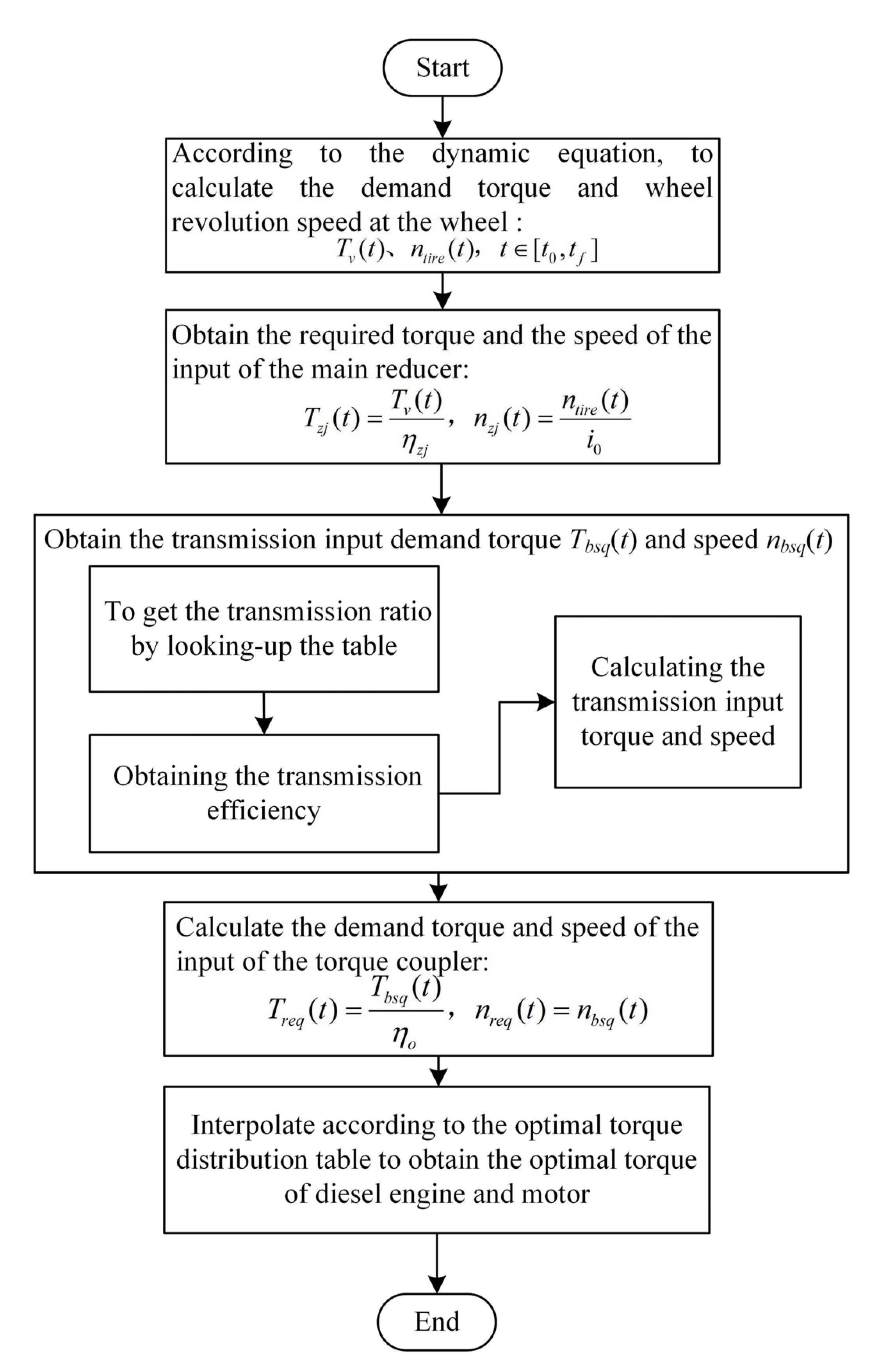
According to the instantaneous optimization control strategy, the optimal torque distribution of the diesel engine and motor during tractor operation is solved, as shown in
Figure 8.
The specific solving steps are shown as follows:
According to the dynamic equation, calculate the required torque
Tv(
t) and wheel speed
ntire(
t) at the wheel of the entire machine.
where
Pv(
t) is the required power at the wheels of the entire machine.
Obtain the required torque
Tzj(
t) and speed
nzj(
t) for the input of the main reducer.
Obtain the required transmission input torque Tbsq(t) and speed nbsq(t).
First, according to the torque required by the main reducer and the tractor speed, the transmission ratio is calculated by looking up the table. Then, the transmission efficiency is obtained by looking up the transmission ratio and torque table. Finally, the transmission input torque and speed are calculated using the transmission speed ratio and efficiency.
Calculate the required torque
Treq(
t) and speed
nreq(
t) of the torque coupler input.
The required torque Treq(t) and speed nreq(t) at the input end of the torque coupler obtained in the previous step are interpolated according to the optimal torque distribution table. Obtain the optimal torque distribution of the diesel engine and motor during tractor operation.
4.2. Energy-Saving Control Strategy Based on Power Following
4.2.1. Control Principle Based on Power Following
As a comparative control strategy, the power following energy-saving control strategy, which is also a rule-based control strategy, is considered. Taking the ratio of the rated power between the diesel engine and motor as the distribution ratio, the power demand of the entire machine is allocated according to the fixed proportion to fully leverage the working capacity of the diesel engine and motor.
4.2.2. Solving Process of Power Following Energy-Saving Control
According to the operating conditions of the hybrid electric tractor and dynamic model analysis conducted on the entire machine, the power required of the entire machine Preq and diesel engine speed ne can be obtained. Accordingly, the required torque of the entire machine Treq can be obtained.
According to the rated power of the diesel engine and motor, the torque distribution proportion coefficient K can be determined, as follows:
where
Perated and
Pmrated are the rated powers of the diesel engine and motor, respectively.
According to the torque distribution proportion coefficient K, the respective working torques of the diesel engine and motor can be obtained using the following equations:
The constraint conditions are as follows:
5. Result Analysis
Two types of energy-saving control strategies were simulated and tested for the two typical working conditions of rotary tillage and plowing. Accordingly, the simulation results were compared and analyzed. The superiority of the energy-saving control strategy based on instantaneous optimization was verified.
5.1. Analysis of Results Obtained Rotary Tillage Condition
During the rotary tillage operation of the tractor, the PTO works independently and is unaffected by the driving conditions of the tractor. The torque and speed characteristics are presented in
Figure 9. The driving speed of the tractor rotary tillage operation is shown in
Figure 10.
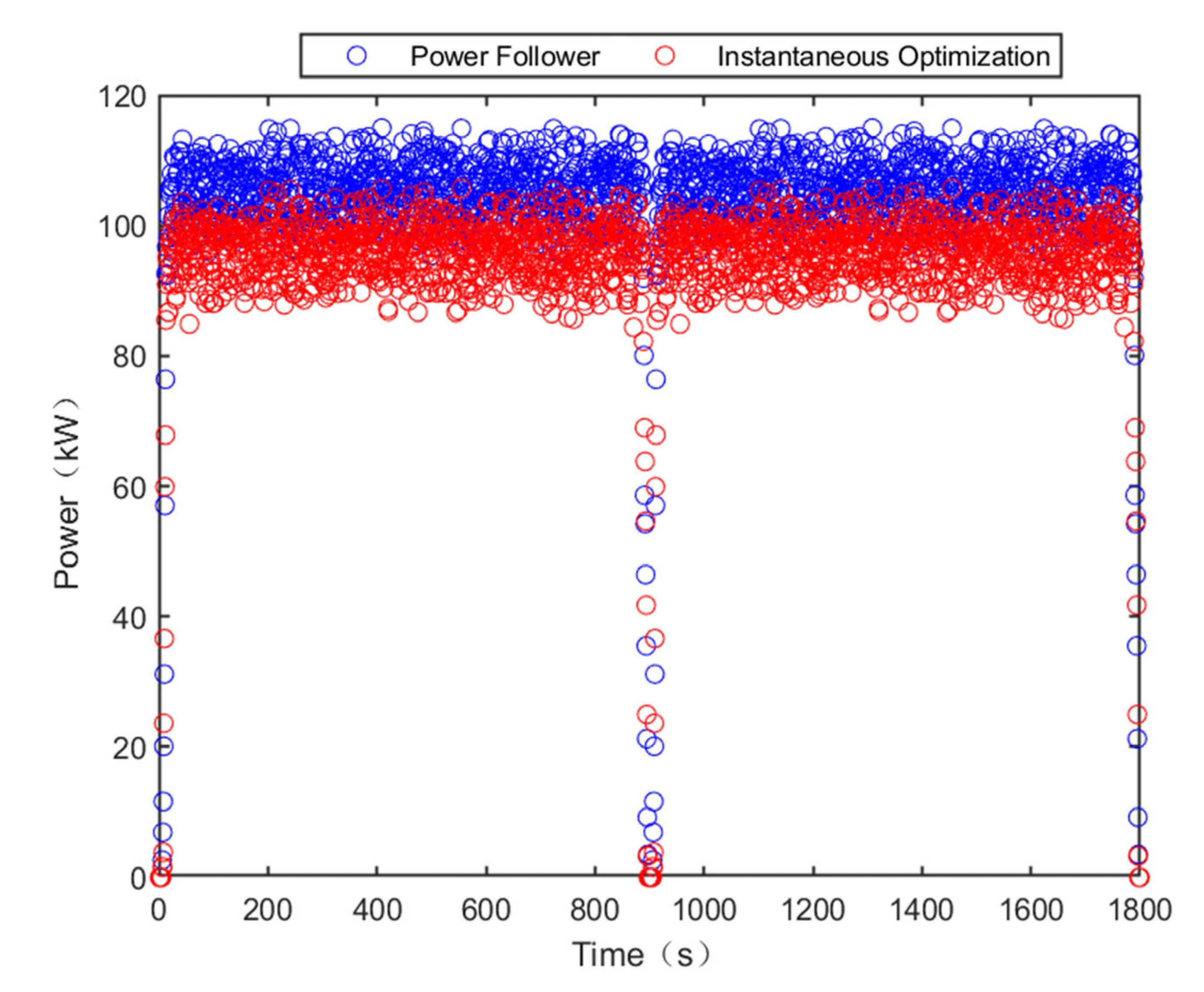
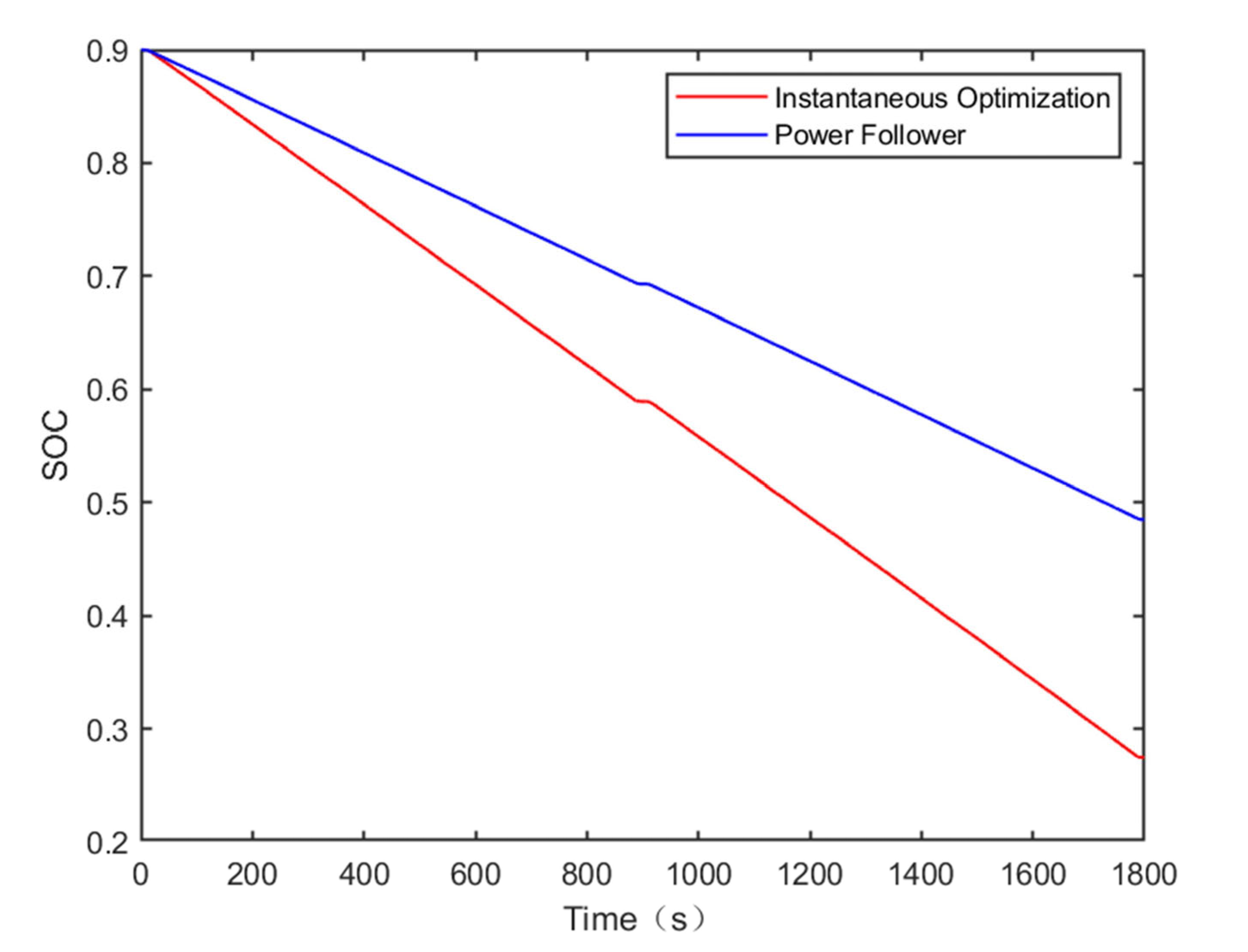
With respect to the tractor rotary tillage operations in the two control strategies, the motor power is shown in
Figure 11; diesel power is shown in
Figure 12, and battery SOC value variations are shown in
Figure 13.
From the simulation results, it can be seen that the load of the hybrid tractor is large, reaching 140 kW under rotary tilling conditions. Utilizing the energy-saving control strategy based on instantaneous optimization, the working power of the motor reaches more than 80% of the load. The working power of the diesel engine is mostly concentrated at 95 kW. The initial SOC value is 0.90, while the final value is 0.27. Using the power following energy-saving control strategy, the working power of the motor is relatively small and concentrated at approximately 20 kW. The maximum power of the diesel engine is approximately 115 kW, while the minimum power is approximately 100 kW. The initial SOC value is 0.90, while the final value is 0.48.
The MAP of the two control strategies for the diesel engine and motor under rotary tilling operation are presented in
Figure 14 and
Figure 15, respectively.
The control strategy based on instantaneous optimization can dynamically adjust the operating regions of the motor and diesel engine according to the change of torque demand; subsequently, the diesel engine works near the optimal power curve with good dynamics and small power. The torque distribution of the energy-saving control strategy based on power following is based on the given ratio, where the adjustable range is small. The working area of the diesel engine is large, whereas that of the motor is small.
5.2. Analysis of Results Under Plow Condition
The tractor plowing speed is shown in
Figure 16, and the plowing resistance is shown in
Figure 17.
For tractor plowing operations conducted using the two control strategies, the motor power is shown in
Figure 18, diesel power is shown in
Figure 19, and battery SOC value variations are shown in
Figure 20.
It can be seen from the simulation results that under plowing conditions, based on the energy-saving control strategy of instantaneous optimization, the working power of the motor is dispersed while that of the diesel engine is concentrated. The diesel engine power is mostly between 85 and 105 kW. The initial SOC value is 0.90, while the final value is 0.42. Based on the power following the energy-saving control strategy, the working power of the motor was concentrated between 17 and 24 kW. The power of the diesel engine is large over a significant range between 85 and 130 kW. The initial value of SOC is 0.90, while the final value is 0.50.
The MAP of the diesel engine and motor for the two control strategies under plowing conditions are shown in
Figure 21 and
Figure 22, respectively.
Based on the instantaneous optimization of the energy-saving control strategy, the overall working area of the diesel engine is low, near the optimal power curve. The fuel consumption is low with good dynamic performance. The efficiency within the overall operating region of the motor is also high, which improves the efficiency of the energy utilization. Based on the power following energy-saving control strategy, the working torque of the diesel engine at constant speed is large, the working power is large, and fuel consumption is increased. The overall operating region of the motor has a low efficiency and poor energy utilization.
6. Conclusions
This study describes an energy-saving control strategy for a hybrid tractor based on an instantaneous optimization algorithm. The objective is to minimize the equivalent fuel consumption of the entire machine. The motor torque and diesel engine torque are the control variables, while the state of charge of the power battery is the state variable. Finally, the instantaneous optimal distribution of torque is obtained.
Considering 220 hp tractors as the research object, the simulation models of the main components were built based on the topology of a parallel diesel-electric hybrid tractor. Finally, a control simulation model was built using MATLAB. To solve the problem of low energy utilization efficiency of hybrid tractors, an energy-saving control strategy based on instantaneous optimization is proposed and compared with the energy-saving control strategy based on power following. The results demonstrate that the proposed energy-saving control strategy based on instantaneous optimization effectively improves the energy efficiency of the tractor during plowing and rotary tillage and reduces equivalent fuel consumption. Under rotary tillage condition, the equivalent fuel consumption of an energy-saving control strategy based on power following is 14.46 L, whereas the equivalent fuel consumption of an energy-saving control strategy based on instantaneous optimization is 13.78 L. Accordingly, the equivalent fuel consumption decreases by 4.70%. Under plowing condition, the equivalent fuel consumption is 14.10 L based on the power following energy saving control strategy and 13.21 L based on the instantaneous optimization energy saving control strategy. Accordingly, the equivalent fuel consumption decreases by 6.31%.
The instantaneous optimal control strategy was designed for a 220 hp hybrid tractor, and acceptable results were obtained. In the future, we will design and test an instantaneous optimization control strategy framework that can meet a variety of different types of hybrid tractors. In addition, researchers can improve the energy-saving control effect of hybrid tractors by constructing models of the diesel engine and motor with more accurate dynamic simulation.
Author Contributions
Conceptualization, J.Z. and G.F.; methodology, L.X.; software, G.F.; validation, J.Z., G.F. and L.X.; formal analysis, M.L.; investigation, X.Y.; resources, L.X.; data curation, W.W.; writing—original draft preparation, G.F.; writing—review and editing, J.Z.; visualization, X.Y.; supervision, M.L.; funding acquisition, L.X. All authors have read and agreed to the published version of the manuscript.
Funding
This research was funded by National Key Research and Development Program (Grant No. 2022YFD2001203), Key Scientific and Technological Research Projects in Henan Province (Grant No. 222102240088), and the State Key Laboratory Open Project (Grant No. SKT202200).
Data Availability Statement
Not applicable.
Conflicts of Interest
Wei Wang and Mengnan Liu are employees of YTO Group Corporation, Luoyang 471004, China. The paper reflects the views of the scientists, and not the company.
References
- Liu, Y.Q. New energy development and key technology research and development direction of agricultural machinery. Agric. Mach. Using Maint. 2021, 4, 33–34. [Google Scholar]
- Xie, B.; Wu, Z.B.; Mao, E.N. Development and prospect of key technologies on agricultural tractor. Trans. Chin. Soc. Agric. Mach. 2018, 49, 1–17. [Google Scholar]
- Mariano, G.; Emmi, L.; Benavides, C.; Garcia, I.; Gonzalez-de-Santos, P. Reducing air pollution with hybrid-powered robotic tractors for precision agriculture. Biosyst. Eng. 2016, 143, 79–94. [Google Scholar]
- Till, G.; Speth, D.; Krail, M.; Wietschel, M.; Oberle, S. Pathways to Carbon-Free Transport in Germany until 2050. World Electr. Veh. J. 2022, 13, 136. [Google Scholar]
- Francesco, M.; Aurelio, S. Analysis of a Parallel Hybrid Electric Tractor for Agricultural Applications. Energies. 2020, 13, 3055. [Google Scholar]
- Yu, P.L.; Li, M.; Wang, Y.; Chen, Z. Fuel Cell Hybrid Electric Vehicles: A Review of Topologies and Energy Management Strategies. World Electr. Veh. J. 2022, 13, 172. [Google Scholar] [CrossRef]
- Deng, X.T.; Zhu, S.H.; Qian, Z.X.; Zhang, Y. Research and development on power coupling device of hybrid electric tractor. Trans. Chin. Soc. Agric. Eng. 2012, 28, 29–34. [Google Scholar]
- Li, H.; Song, Z.H.; Xie, B. Plowing Performance Simulation and Analysis for Hybrid Electric Tractor. Appl. Mech. Mater. 2013, 2555, 505–511. [Google Scholar] [CrossRef]
- He, H.G.; Meng, X.F. A Review on Energy Management Technology of Hybrid Electric Vehicles. Trans. Beijing Inst. Technol. 2022, 42, 773–783. [Google Scholar]
- Zhang, F.Q.; Hu, X.S.; Xu, K.H.; Tang, X.L.; Cui, Y.H. Status and Prospects for Model Predictive Energy Management in Hybrid Electric vehicles. J. Mech. Eng. 2019, 55, 86–108. [Google Scholar] [CrossRef] [Green Version]
- Luo, G.J. Research on Energy Management Strategy of Series Diesel-Electric Hybrid Tractor. Master’s Thesis, Department of Agricultural Engineering, Naju, China, 2019. [Google Scholar]
- Xu, L.Y.; Zhang, J.J.; Liu, M.N.; Zhou, Z.; Liu, C. Control algorithm and energy management strategy for extended range electric tractors. Int. J. Agric. Biol. Eng. 2017, 10, 35–44. [Google Scholar]
- Fang, S.P.; Zhou, Z.L.; Xu, L.Y. Energy management strategy for tandem hybrid tractors. J. Henan Univ. Sci. Technol. Nat. Sci. 2015, 36, 61–66. [Google Scholar]
- Zhang, Z.; Zhang, T.; Hong, J.; Zhang, H.; Yang, J. Energy Management Optimization of Master–Slave Hybrid Electric Vehicle under Rule-Based Control Strategy. Energy Technol. 2022, 10, 2200630. [Google Scholar] [CrossRef]
- Lee, H.S.; Kim, J.S.; Park, Y.I.; Cha, S.W. Rule-based power distribution in the power train of a parallel hybrid tractor for fuel savings. Int. J. Precis. Eng. Manuf.-Green Technol. 2016, 3, 231–237. [Google Scholar] [CrossRef]
- Matteo, S.; Anselma, P.G.; Misul, D.A.; Belingardi, G. Exploitation of a Particle Swarm Optimization Algorithm for Designing a Lightweight Parallel Hybrid Electric Vehicle. Appl. Sci. 2021, 11, 6833. [Google Scholar]
- Qian, L.J.; Qiu, L.H. Optimal control of a hybrid electric vehicle based on fuzzy-PID torque identification. China Mech. Eng. 2015, 26, 1752–1759. [Google Scholar]
- Shi, D.P.; Chu, L.; Guo, J.; Tian, G.; Feng, Y.; Li, Z. Energy Control Strategy of HEB Based on the Instantaneous Optimization Algorithm. IEEE Access 2017, 5, 19876–19888. [Google Scholar] [CrossRef]
- Liu, M.N.; Zhao, S.; Han, B.; Lei, S.; Xu, L. Multi-Objective Optimization and Test of a Tractor Drive Motor. World Electr. Veh. J. 2022, 13, 43. [Google Scholar] [CrossRef]
- Wang, Y.; Zeng, X.H.; Song, D.F.; Yang, N.N. Optimal rule design methodology for energy management strategy of a power-split hybrid electric bus. Energy. 2019, 185, 1086–1099. [Google Scholar] [CrossRef]
- Adeleke, O.P.; Li, Y.; Chen, Q.; Zhou, W.; Xu, X.; Cui, X. Torque Distribution Based on Dynamic Programming Algorithm for Four In-Wheel Motor Drive Electric Vehicle Considering Energy Efficiency Optimization. World Electr. Veh. J. 2022, 13, 181. [Google Scholar] [CrossRef]
- Sun, D.Y.; Lin, X.Y.; Qin, D.T.; Deng, T. Power-balancing instantaneous optimization energy management for a novel series-parallel hybrid electric bus. Chin. J. Mech. Eng. 2012, 25, 1161–1170. [Google Scholar] [CrossRef]
- Gökce, K.; Ozdemir, A. An instantaneous optimization strategy based on efficiency maps for internal combustion engine battery hybrid vehicles. Energy Convers. Manag. 2014, 81, 255–269. [Google Scholar] [CrossRef]
- Minh, V.T.; Moezzi, R.; Cyrus, J.; Hlava, J.; Petru, M. Parallel Hybrid Electric Vehicle Modelling and Model Predictive Control. Appl. Sci. 2021, 11, 10668. [Google Scholar]
- Zhao, G.F. Modeling and control strategy of hybrid electric vehicle system. Sichuan Aerosp. Voc. Coll. 2022, 12329, 1232902. [Google Scholar]
- Choi, S.C.; Song, B.S.; Kim, Y.J. Torque Assist Strategy for Hybrid Agricultural Tractor with Consideration of Field Operations. Trans. Korean Soc. Mech. Eng.—A 2014, 38, 593–600. [Google Scholar] [CrossRef]
- Xu, L.Y.; Liu, M.N.; Zhou, Z.L. Design of drive system for series hybrid electric tractor. Trans. Chin. Soc. Agric. Eng. 2014, 30, 11–18. [Google Scholar]
- Li, J.F.; Wu, X.; Zhang, X.; Song, Z.; Li, W. Design of distributed hybrid electric tractor based on axiomatic design and Extenics. Adv. Eng. Inform. 2022, 54, 101765. [Google Scholar] [CrossRef]
- Xie, B.; Hao, L.; Zheng-He, S.; En-Rong, M. Powertrain System Design of Medium-sized Hybrid Electric Tractor. Inf. Technol. J. 2013, 12, 7228–7233. [Google Scholar]
- Zhou, Z.L.; Ni, Q.; Xu, L.Y. Parallel hybrid tractor drive train parameter design and performance analysis. J. Henan Univ. Sci. Technol. 2016, 37, 9–15. [Google Scholar]
- Liu, M.N.; Xu, L.Y.; Zhou, Z.L.; Liu, W.G. Establishment of Extended Range Electric Tractor and Its Rotary Cultivator’s Simulation Platforms. China Mech. Eng. 2016, 27, 413–419. [Google Scholar]
- Xu, L.Y.; Zhang, J.J.; Liu, M.N. Torque distribution strategy for extended-range four-wheel drive electric tractor. J. Henan Univ. Sci. Technol. 2017, 38, 80–85. [Google Scholar]
- Li, X.H.; Luo, F.Q.; Tang, D. Drawing engine universal performance characteristics map using ploynomial interpolation. Trans. CSAE 2004, 5, 138–141. [Google Scholar]
Figure 1.
Topology of a diesel–electric parallel hybrid tractor.
Figure 1.
Topology of a diesel–electric parallel hybrid tractor.
Figure 2.
Motor model MAP diagram.
Figure 2.
Motor model MAP diagram.
Figure 3.
Diesel engine model MAP diagram.
Figure 3.
Diesel engine model MAP diagram.
Figure 4.
Power battery internal resistance model.
Figure 4.
Power battery internal resistance model.
Figure 5.
Schematic diagram of the whole machine simulation model.
Figure 5.
Schematic diagram of the whole machine simulation model.
Figure 6.
The flowchart of optimal torque distribution table solves.
Figure 6.
The flowchart of optimal torque distribution table solves.
Figure 7.
Torque distribution under hybrid drive. (a) Torque of the diesel engines. (b) Torque of the motor.
Figure 7.
Torque distribution under hybrid drive. (a) Torque of the diesel engines. (b) Torque of the motor.
Figure 8.
Torque distribution flowchart based on instantaneous optimization.
Figure 8.
Torque distribution flowchart based on instantaneous optimization.
Figure 9.
Torque and tachograph of the PTO.
Figure 9.
Torque and tachograph of the PTO.
Figure 10.
Speed of rotary tillage operations.
Figure 10.
Speed of rotary tillage operations.
Figure 11.
Working power of motor.
Figure 11.
Working power of motor.
Figure 12.
Working power of diesel engine.
Figure 12.
Working power of diesel engine.
Figure 13.
SOC state value changes.
Figure 13.
SOC state value changes.
Figure 14.
Diesel engine operating points.
Figure 14.
Diesel engine operating points.
Figure 15.
Motor operating points.
Figure 15.
Motor operating points.
Figure 16.
Plowing speed.
Figure 16.
Plowing speed.
Figure 17.
Resistance of plowing operation.
Figure 17.
Resistance of plowing operation.
Figure 18.
Working power of motor.
Figure 18.
Working power of motor.
Figure 19.
Working power of diesel engine.
Figure 19.
Working power of diesel engine.
Figure 20.
SOC state value changes.
Figure 20.
SOC state value changes.
Figure 21.
Diesel engine operating points.
Figure 21.
Diesel engine operating points.
Figure 22.
Motor operating points.
Figure 22.
Motor operating points.
Table 1.
Topology of a diesel–electric parallel hybrid tractor.
Table 1.
Topology of a diesel–electric parallel hybrid tractor.
| Name | Parameter | Value (Unit) |
|---|
| Diesel engine | Rated power | 162 (kW) |
| Rated speed | 2500 (rpm) |
| Maximum torque | 800 (Nm) |
| Motor | Rated power | 30 (kW) |
| Rated speed | 3000 (rpm) |
| Rated torque | 96 (Nm) |
| Power battery | Energy capacity | 70 (Ah) |
| Rated voltage | 360 (V) |
| SOC | 0.90–0.25 |
Table 2.
Hybrid tractor transmission ratios and theoretical speeds.
Table 2.
Hybrid tractor transmission ratios and theoretical speeds.
| Forward Gear | Transport III | Transport II | Transport I | Working II | Working I | Amble II | Amble I |
|---|
| Ratio | 0.864 | 1.377 | 2.307 | 3.296 | 4.963 | 7.405 | 11.208 |
| Theoretical speed (km/h) | 39.980 | 28.668 | 17.164 | 11.977 | 7.654 | 5.231 | 3.522 |
| Disclaimer/Publisher’s Note: The statements, opinions and data contained in all publications are solely those of the individual author(s) and contributor(s) and not of MDPI and/or the editor(s). MDPI and/or the editor(s) disclaim responsibility for any injury to people or property resulting from any ideas, methods, instructions or products referred to in the content. |
© 2023 by the authors. Licensee MDPI, Basel, Switzerland. This article is an open access article distributed under the terms and conditions of the Creative Commons Attribution (CC BY) license (https://creativecommons.org/licenses/by/4.0/).


