1. Introduction
In the global agricultural machinery industry, tractors are the largest category. However, traditional internal combustion engine tractors consume a large amount of fossil fuels and have poor emissions, resulting in energy shortages and environmental pollution [
1,
2,
3]. With the advocacy of protecting the environment and reducing energy consumption around the world, it is of great significance to study new energy-saving tractors [
4,
5,
6]. In the last decade, strict regulations were progressively applied to the Non-Road Mobile Machineries (NRMM). The field of NRMM is now more than ever considering the adoption of electric systems to reduce the amount of pollutant emissions and to improve energy efficiency per unit of work [
7]. Pure electric agricultural tractors have a short operating mileage and are not suitable for long-term heavy-duty traction operations, whereas agricultural hybrid tractors can solve this problem by configuring two or more power sources under appropriate control strategies [
8].
As the core control strategy of hybrid tractor, energy management strategy has a direct impact on the power, economy, comfort, and emission of the whole machine, so it has become the focus and difficulty of research in the field of hybrid electric vehicles [
9]. Currently, there are primarily two classifications of energy management approaches: control strategies based on rules and those based on optimization [
10,
11,
12]. The development cost of the rule-based control strategy is low, simple, and intuitive, and has strong practicability. It is extensively utilized in a diverse range of hybrid automobiles. For four-wheel drive hybrid electric vehicles, Ma et al. [
13] proposed a rule-based logic threshold energy management strategy model to control the torque distribution of the hybrid system and realize the reasonable selection of the working mode. The results show that compared with the comprehensive fuel consumption of the prototype traditional vehicle, the designed control strategy can reduce the fuel consumption. Lv et al. [
14] proposed an energy management strategy based on rule-based fuzzy control for plug-in hybrid electric vehicles. The results show that the proposed strategy significantly reduces fuel consumption. Luo et al. [
15] proposed a control strategy based on the optimal use of electric energy to solve the poor fuel economy problem of hybrid vehicles on longer driving distances. The results show that this strategy can significantly improve the vehicle’s fuel economy over a longer driving range. However, deterministic rule-based control strategies are determined based on the experience of the designer. It has high reliability but poor adaptability to working conditions. For the fuzzy control strategy, the utilization of a basic fuzzy information processing approach in the control strategy may result in compromised control precision and decreased dynamic quality of the system [
16].
Control strategies that utilize optimization require minimizing or maximizing a cost function, which typically serves as a gauge for the control objective. Geng et al. [
17] proposed a multi-objective energy management strategy based on particle swarm optimization (PSO) aiming to reduce vehicle energy consumption and control battery power at the same time. The findings indicate that the suggested approach is capable of accomplishing two objectives simultaneously, namely decreasing car energy usage and managing battery energy. Zhang et al. [
18] proposed an energy management strategy based on instantaneous torque optimization for hybrid tractors. The findings indicate that the suggested approach effectively manages the operational status of the electric motor and diesel engine, leading to lower overall fuel usage when compared to the power-following energy management technique. Chen et al. [
19] proposed a power distribution energy management strategy for plug-in hybrid electric vehicles. A series of quadratic equations are used to estimate the fuel rate of the vehicle, and the battery current is used as input, and the pontryagin minimum principle (PMP) is introduced to solve the problem. The results show that the proposed algorithm is able to reduce fuel consumption compared to charge depletion (CD) and charge maintenance (CS) modes. However, the instantaneous optimization method can only ensure the optimal fuel economy at each moment, but cannot guarantee the final global optimal. The PMP control strategy can only achieve an approximate global optimum.
In order to comply with the new energy trend and improve the energy utilization rate of agricultural machinery, a hybrid tractor used in agriculture is taken as the research object, which combines diesel and electric power sources. Then a global optimal energy management strategy based on dynamic programming (DP) is proposed in this study [
20,
21,
22,
23,
24]. By optimizing the torque distribution of the diesel engine and the electric motor, the total energy consumption cost of the whole machine can be reduced while ensuring the power performance. The remainder of this study is organized as follows. In
Section 2, presents a hybrid tractor topology and its main performance parameters. In
Section 3, simulation modeling of major components of the hybrid tractor is described. A global optimal energy management strategy for hybrid tractors is designed in
Section 4.
Section 5 delineates the description of simulation verification and discussion. Finally, the conclusions drawn from the study are summarized in
Section 6.
2. Topology and Principal Parameters of Hybrid Tractors
Taking a diesel-electric parallel agricultural hybrid tractor as the research object, the establishment of the hybrid tractor topology and the performance parameters of its main components are stated.
2.1. Hybrid Tractor Topology
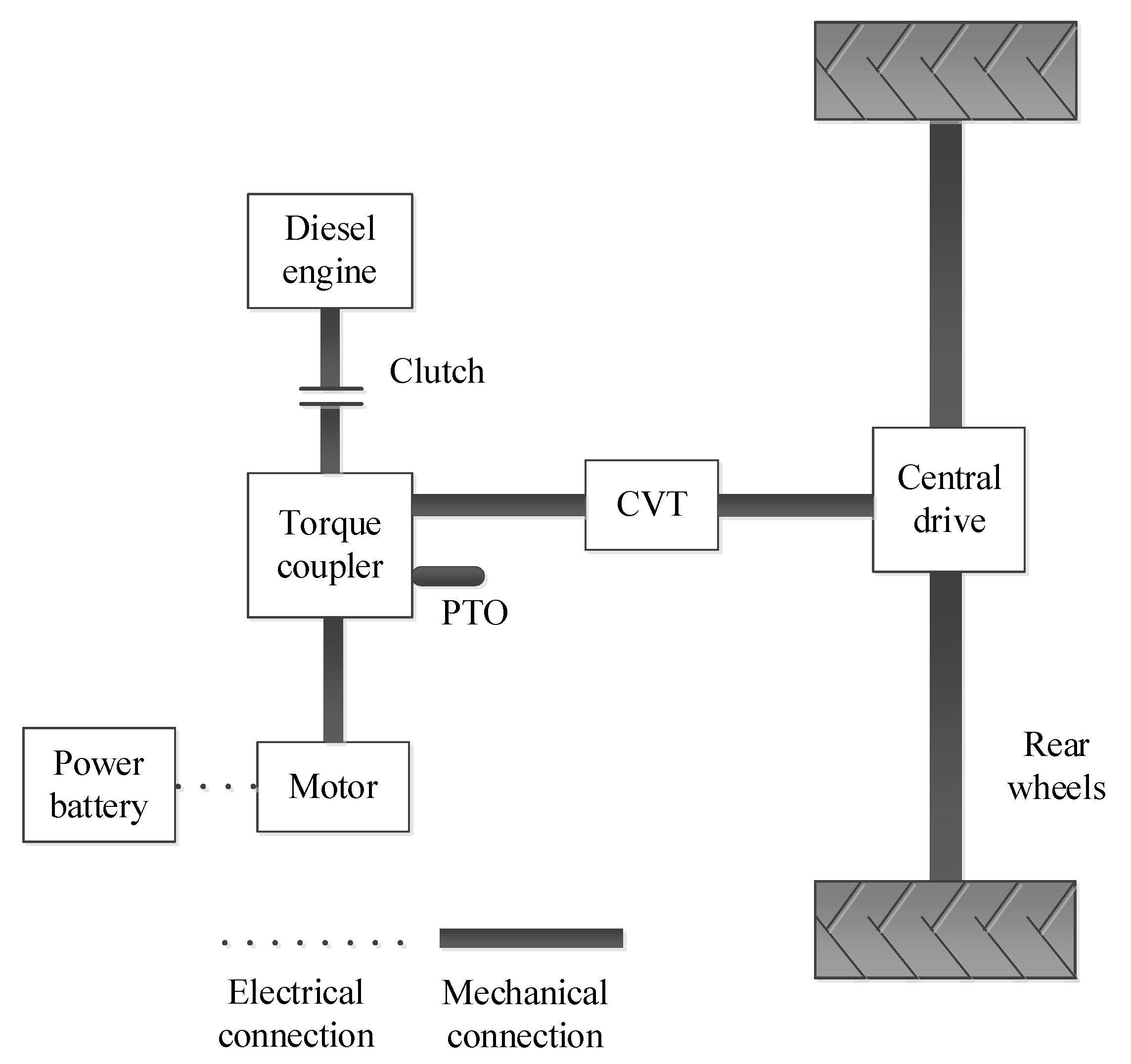
Figure 1 shows the topology of a hybrid tractor equipped with continuously variable transmission (CVT), which has two power sources, namely a diesel engine and an electric motor. The two can work together or independently. The output torque of the diesel engine and the motor are transmitted to the CVT input shaft and the power take off (PTO) power output shaft through the torque coupling, which are served as the source of power for the central transmission and the PTO, respectively.
The vehicle controller and diesel engine, power battery, clutch, electric motor, and CVT are connected through the controller area network (CAN) bus. According to the overall power demand of the whole system and the corresponding state of charge (SOC) index of the power battery, the torque output of the diesel engine and the motor is dynamically allocated to the whole machine through the control strategy. Consequently, the hybrid tractor has the capacity to attain the most optimal combination of power and economic efficiency.
2.2. Main Performance Parameters of Hybrid Tractor
The present investigation employs a diesel-electric parallel hybrid tractor as the research object and aims to investigate its energy management strategy [
25,
26,
27]. The parameters characterizing primary components of the hybrid tractor are shown in
Table 1.
3. Model Construction of Hybrid Tractor
Taking into account the topology of the hybrid tractor, an analysis was carried out to model its principal components, which encompass the transmission system, the diesel engine, the motor, the dynamics of the rotary tillage unit, the CVT, and the power battery model. Finally, the simulation model of the hybrid tractor was developed.
3.1. Hybrid Tractor Transmission System Model
The motor and diesel engine are responsible for supplying the necessary energy to operate the hybrid tractors. The total power of the tractor is derived from the input of the torque coupler, represented by the following expression:
where
Pereq and
Pmreq are the diesel engine and motor required power, respectively.
nreq and
Treq denote the required speed and torque at the input end of the torque coupler, respectively.
ηe and
ηm are the working efficiencies of the diesel engine and motor, respectively.
Pe and
Pm denote the power required for the diesel engine and motor, respectively.
Te,
Tm,
ne and
nm denote the torques and speeds of the diesel engine and motor, respectively.
Based on the tractor topology depicted in
Figure 1, analyze the power transmission process. The relationship between the wheel and the diesel engine speeds is expressed as follows:
where
i0 and
icvt denote the main reducer and CVT speed ratios, respectively.
ne and
ntire represent the diesel engine and driving wheel speeds, respectively.
r denotes the driving wheel radius of the hybrid tractor.
v represents the speed of the hybrid tractor during working.
3.2. Dynamic Model of Rotary Tillage Unit
The power balance relationship of the unit when the hybrid tractor is towing the rotary tillage unit is similar to that in the literature [
18]. Based on the previous research results of the research group, combined with the hybrid tractor topology in this paper. In particular, CVT and PTO shafts are connected with torque couplings [
28,
29,
30]. The power balance equation for the rotary tillage process of the hybrid tractor can be expressed as follows:
where
ηzy, ηcvt, and
ηo represent the central drive efficiency, CVT efficiency, and torque-coupler efficiency, respectively.
Pr and
Pdrive denote the rotary cultivator power and tractor travel power consumptions, respectively.
3.3. Motor Model
Electric motors can convert between electrical energy and mechanical energy. The relationship between the conversion efficiency, torque and speed is expressed as follows:
The numerical model method is employed to establish the motor model, whereby the spline interpolation method is utilized to determine the correlation between the efficiency, torque, and speed of the motor system. This approach is underpinned by experimental data pertaining to motor efficiency. This method has a fast calculation speed and can meet the rapidity requirements of simulation. Therefore, it is suitable for control strategy research. The numerical model representing the efficiency of the motor is shown in
Figure 2.
3.4. Diesel Engine Model
The modeling of diesel engines can be classified into two principal categories: mathematical modeling method and experimental modeling method [
31]. The mathematical modeling method needs to analyze the transient characteristics of the diesel engine, and test the detailed parameters of each process. Also, the process is complex and the calculation speed is slow. The experimental modeling method is based on the measured data of the diesel engine, and constructs the MAP diagram by formulating the mapping relationship of the diesel engine torque and fuel consumption rate corresponding to the speed or throttle opening. In the simulation process, only the output and input parameters of the diesel engine are concerned, and its transient characteristics are ignored. Therefore, the experimental modeling method is used here to obtain the numerical model of the fuel consumption rate of the diesel engine, as shown in
Figure 3.
3.5. CVT Model
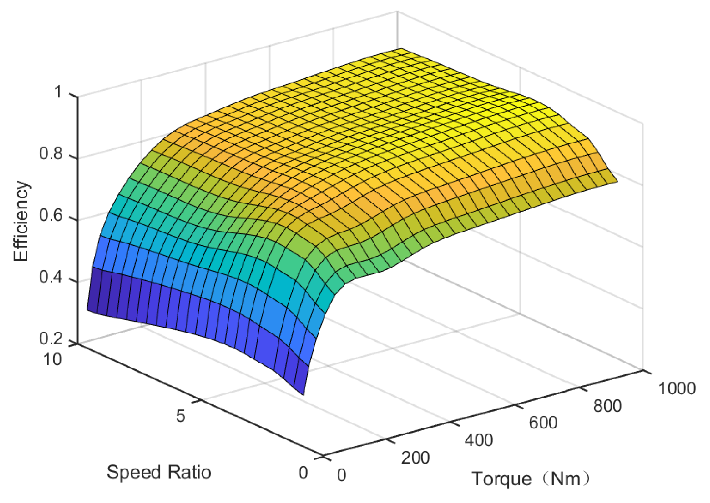
The CVT has a continuously variable speed ratio, and can adjust the speed ratio in real time to adjust the working point of the motor and the diesel engine. Hence, it is evident that both the motor and the diesel engine can operate in the realm of optimal efficiency. This paper only considers the transmission efficiency of CVT, ignores its dynamic response characteristics, and does not consider the complex hydraulic actuators in CVT. A CVT numerical model was established based on bench test data [
32]. CVT transmission efficiency is related to its input torque and speed ratio, which can be expressed as:
where
Tcvt_in is the input torque of the CVT.
The relationship surface of CVT efficiency, speed, and torque are obtained by interpolation fitting method. That is the numerical model of CVT efficiency, as shown in
Figure 4.
The calculation formula of CVT output torque and output speed is as follows:
where
ncvt_in and
ncvt_out are the CVT driving pulley and driven pulley speeds, respectively.
Tcvt_out is the CVT output torque.
3.6. Power Battery Model
There are two prevalent battery models in common use, namely the resistance-capacitance model and the internal resistance model [
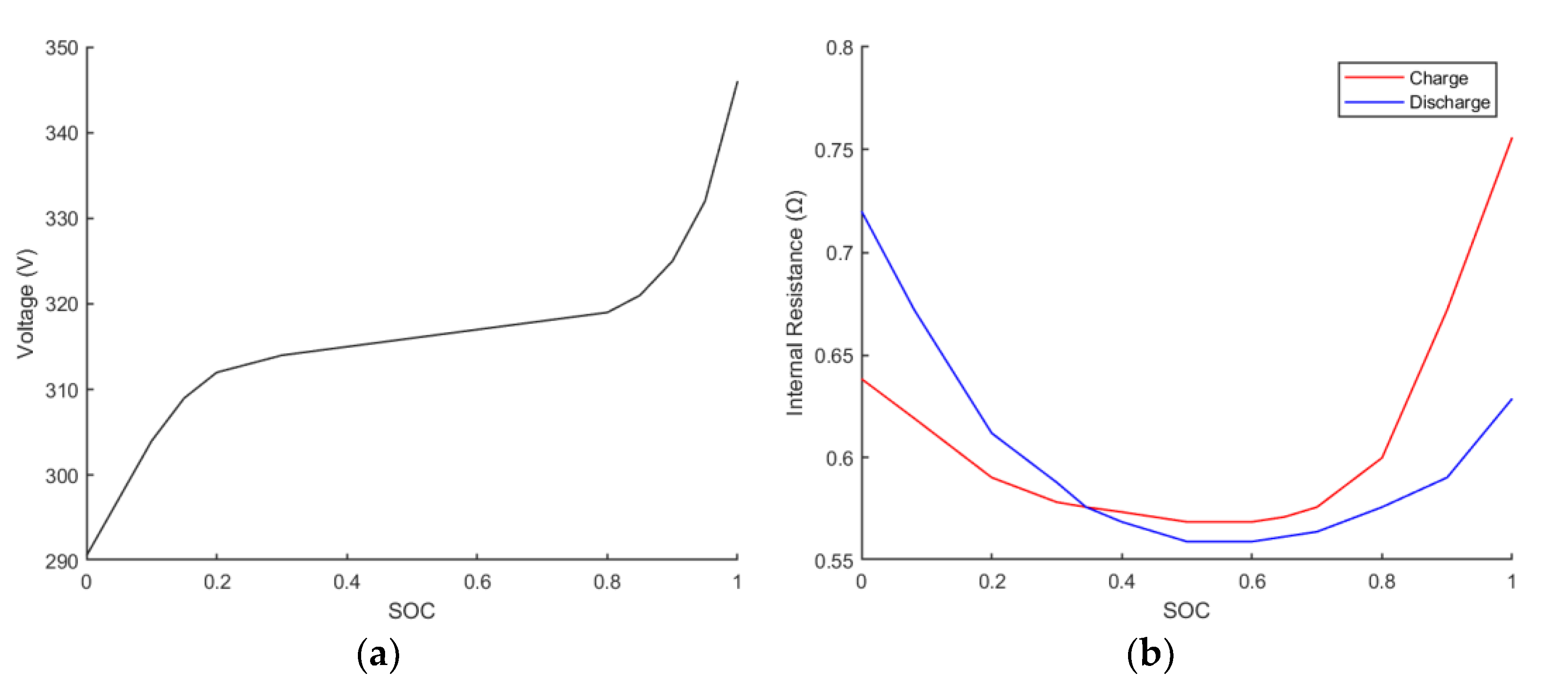
33]. The internal resistance model regards the battery pack as an equivalent circuit in series with an ideal voltage source and an internal resistance, which belongs to the first-order model. The resistance-capacitance model regards the battery pack as a circuit composed of two capacitors and three resistors, which belongs to the second-order model. In comparison, the internal resistance model is simple to model and has good applicability to various working conditions of the power battery. Therefore, the internal resistance model is adopted here. The power battery is equivalent to a circuit model of an ideal voltage source and a resistor connected in series, the mathematical equation is simple, and it is convenient for calculation and modeling.
The relationship curve between the electromotive force of the power battery, the internal resistance of charge or discharge and the SOC of the power battery is shown in
Figure 5.
The equation for calculating the required power of the power battery is as follows:
where
ηbat denotes the battery charging or discharging efficiency.
Pm greater than 0 is discharging, and
Pm less than 0 is charging.
Pbat represents the required power of the power battery.
The formulas for calculating the SOC and current of the power battery are as follows:
where
I(
t),
U(
t), and
R(
t) are the output current, output voltage, and internal resistance of the power battery, respectively.
Qb denotes the rated power battery capacity.
SOC(
t) and
SOC(
t + 1) are the SOC at the current and next moment, respectively. ∆
t is the time step.
3.7. Machine Simulation Model
The simulation model of the entire hybrid tractor has been constructed using MATLAB, taking into account the characteristics of its transmission system, as depicted in
Figure 6. The machine simulation model includes the transmission system model, dynamic model of rotary tiller, diesel engine model, motor model, and power battery model. The controller collects signals based on the working conditions of the tractor. The required power and speed (
Preq and
nreq) of the whole machine are obtained through calculation and processing according to Equations (1), (4) and (6). Inside the controller, the required power of the whole machine is allocated according to the established control strategy (including the proposed and compared strategies). Then output the corresponding motor required power (
Pmreq) and diesel engine required power (
Pereq) as the input of the motor model and diesel engine model.
The motor model and diesel engine model work in accordance with prescribed instructions, output the corresponding required torque and speed (Tmreq, nmreq, Tereq, and nereq) and transmit the power to the rotary tiller dynamic model (Pdrive and Pr) through the transmission system model. At the same time, the power battery model performs energy transfer according to the required power of the motor model (Pbat).
4. Energy Management Strategy Design
This section details the design process of a globally optimized energy management strategy based on dynamic programming. Firstly, an energy management optimization model is built, and then the principle of dynamic programming algorithm is expounded. Finally, the dynamic programming algorithm is combined with the energy management optimization model, and the solution process of the dynamic programming control strategy is described. In addition, the control principle of the power-following energy management strategy is briefly described.
4.1. Global Optimal Energy Management Strategy Based on Dynamic Programming
4.1.1. Energy Management Optimization Model
Hybrid tractors derive their power from two distinct sources, namely electricity and diesel fuel. In order to measure the two kinds of energy uniformly, the energy consumption economy function is defined as the sum of electric energy cost and diesel engine fuel cost. The goal of energy management is to minimize the total cost of energy consumption by optimally allocating the operating states between the diesel engine and the electric motor. The total cost of energy consumption during hybrid tractor operation can be defined as:
where
Qc(t) is the total cost of energy consumption.
Qf(
t) denotes the instantaneous fuel consumption.
tf denotes the end moment.
jm and
je represent the prices per kWh of electricity and liter of oil, respectively.
According to the Equation (13), the power battery SOC changes as follows:
4.1.2. Dynamic Programming Algorithm
Dynamic programming is a multi-step optimization algorithm, which divides the multi-stage decision-making process into stages. Then properly selects state variables and decision variables to define the optimal objective function. Thus, the problem can be transformed into a family of sub-problems of the same type, and finally solved one by one. The solution begins with the boundary conditions. The process proceeds in reverse order, and the optimization is recursively searched segment by segment. When solving each sub-problem, the optimal result of the previous sub-problems must be used. The optimal solution to the last subproblem is the optimal solution to the entire problem. Using reverse solution, according to the given tractor operating conditions, it is divided into m parts.
When establishing the dynamic programming algorithm, set the sampling time as 1 s. Computation starts at m stage and goes forward. When calculating each stage, with the optimal control as the goal, the optimal control variable u(k) is calculated by global search under the given component parameters. To ensure the lowest fuel consumption of the diesel engine and maintain the power SOC within the range of the set value. Accordingly, the optimal optimization result is calculated. The decision variables, namely the control variables, include motor torque, diesel engine torque, motor speed, diesel engine speed, and CVT gear ratio. The power battery SOC is defined as the state variable, and the total energy consumption cost is set as the optimal objective function. Based on this, a DP energy management strategy is established.
The state variables are as follows:
At the same time, the state variables need to be discretized, as follows:
where
m is the discrete state space dimension, that is, the number of discrete points.
The control variables are as follows:
In the calculation process, the control variables are discretized as follows:
where
j denotes the number of discrete points.
The state equation of the system is as follows:
According to Equations (14) and (16), the optimal objective function of dynamic programming is constructed as follows:
where
J is the minimum cumulative energy consumption total cost in the operation cycle.
Q is the total cost of energy consumption at a certain stage.
Constraints can be expressed as:
where
Tm min,
Tm max,
Te min, and
Te max represent the minimum and maximum torques of the electric motor and diesel engine at the current moment, respectively.
nm min,
nm max,
ne min, and
ne max represent the minimum and maximum speeds of the electric motor and diesel engine at the current moment, respectively.
icvt min and
icvt max denote the minimum and maximum speed ratios of the CVT, respectively.
SOCmin and
SOCmax are the least and greatest values permitted by the SOC, respectively.
4.1.3. Dynamic Programming Control Strategy Solution Process
The control strategy based on dynamic programming refers to the use of cyclic iteration method to reasonably optimize the working torque of diesel engine and electric motor, so as to minimize the total cost of energy consumption of the whole machine. The solution process is depicted in
Figure 7.
- 1.
Based on the operative circumstances, the dynamic programming algorithm is set to 1800 stages (m = 1800). According to the known vehicle speed and vehicle parameters in each stage, the required torque Tv(k) of the tractor at the wheels of each stage is obtained through the dynamic equation.
where
Pv(
k) denotes the required power at the wheel of the tractor.
- 2.
Obtain the required torque Tzy(k) at the input end of the central drive.
where
Tzy(
k) represent the required torque at the input end of the central drive.
- 3.
Obtain the required torque Tcvt_in at the input end of the CVT. Firstly, the CVT speed ratio is obtained according to the central transmission demand torque and the tractor speed look-up table, and the output torque of the CVT is calculated on the basis of the known speed ratio. Then the CVT efficiency is obtained through the CVT speed ratio and torque look-up table. Accordingly, the CVT input torque is calculated from the CVT speed ratio and efficiency.
- 4.
Obtain the required torque Treq(k) at the input end of the torque coupler.
where
iPTO(
k) denotes the PTO gear ratio inside the torque coupling.
- 5.
According to the required torque Treq(k) and speed nreq(k), based on the set SOC upper and lower limits, CVT speed ratio, maximum and minimum torque values of diesel engine and electric motor, diesel engine fuel consumption rate, and electric motor efficiency, interpolation calculation each stage may control variables.
- 6.
From all the possible control variables calculated, select the speed and torque of the diesel engine and motor that satisfy the constraints of the Equation (22). Calculate the control variables and state parameter values of each component when the objective Equation (21) is the minimum value. The state change and interpolation calculation of the control variables are shown in
Figure 8.
When the state variables of
x(
i) and
x(
i + 1) change, the optimal control variable at stage
k is
uk. In the
k + 1 stage, the optimal control variable
uk+1 is obtained by interpolating
uk+1(
j) and
uk+1(
j + 1). The red line in
Figure 8 shows that in the
k + 1 stage, the state variable
x(
i + 1) exceeds the set upper and lower limits of the SOC.
- 7.
Let m = m − 1, carry out the operation of the next stage until k = 0, get the optimal control parameter and SOC value, and the operation ends.
4.2. Power following Energy Management Strategy
The power-following energy management strategy is adopted as a comparative control strategy, which is simple in design and easy to implement. Moreover, it is a rule-based control strategy. The power-following energy management strategy employs the ratio of the diesel engine’s rated power to that of the electric motor as the distribution ratio. The power demand of the whole machine is allocated based on a fixed ratio, which controls the operational status of both the diesel engine and electric motor, and give full play to the working capabilities of both.
5. Simulation Results and Analysis
During rotary tillage operations of the hybrid tractor, the PTO operates independently and is not affected by the driving conditions of the tractor. According to the field rotary tillage operation experiment, the speed, driving resistance, and PTO torque and rotational speed during the operation process are obtained. Then the measured data are input into the simulation model. Its torque speed is shown in
Figure 9, and the rotary tillage operation speed is displayed in
Figure 10.
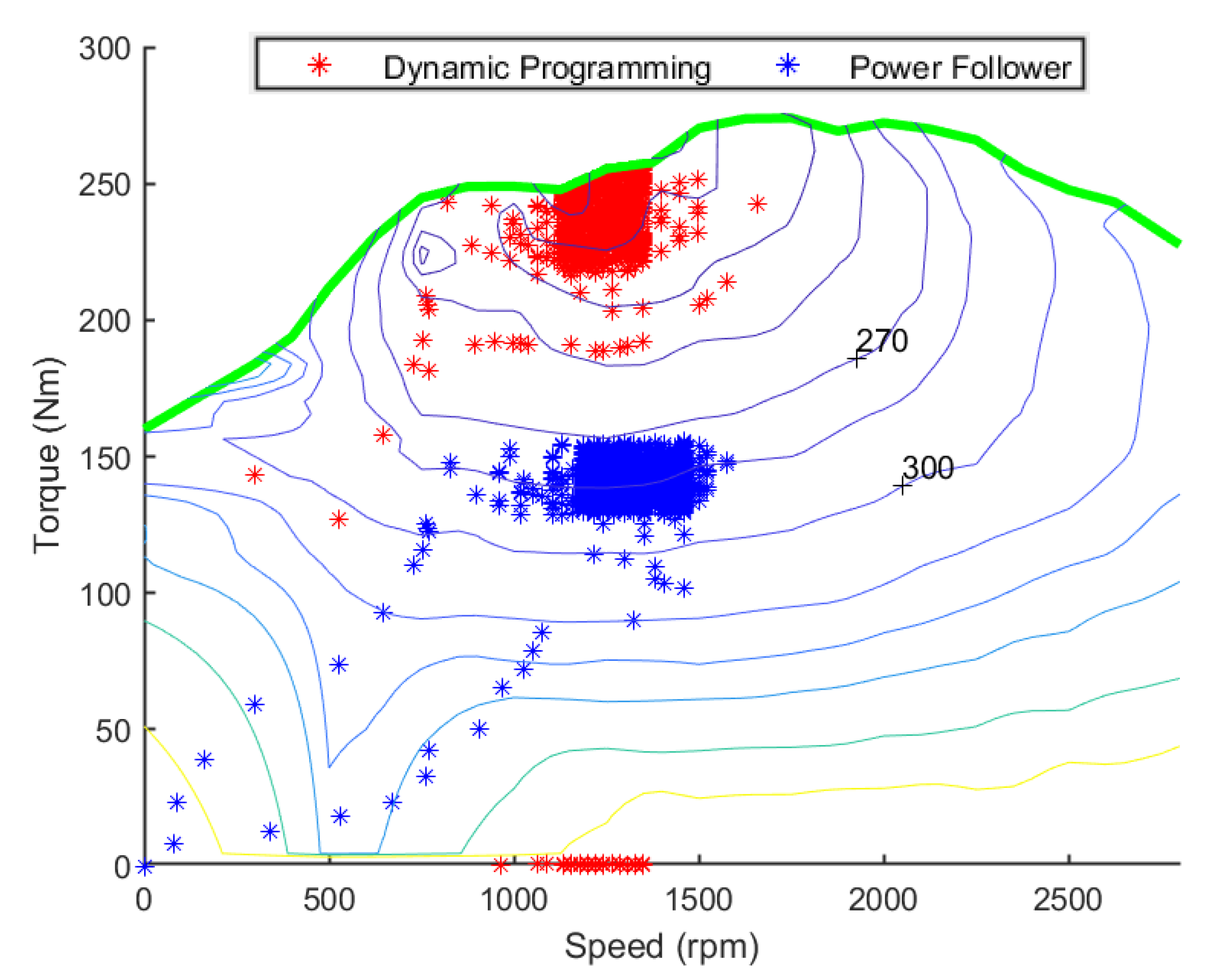
Figure 11 and
Figure 12 show the MAP diagrams of diesel engine and electric motor under two control strategies during hybrid tractor rotary tillage operation. Under the global optimal energy management strategy based on dynamic programming, the working torque of the motor is large, and some negative torques appear. The diesel engine also produces a large working torque, and it is concentrated in the high-efficiency area. Under the power following energy management strategy, the motor generates a small working torque, and there is no negative torque. The working torque of the diesel engine is also small, and the efficiency of the working area is low.
Under the two control strategies, the change of CVT speed ratio is shown in
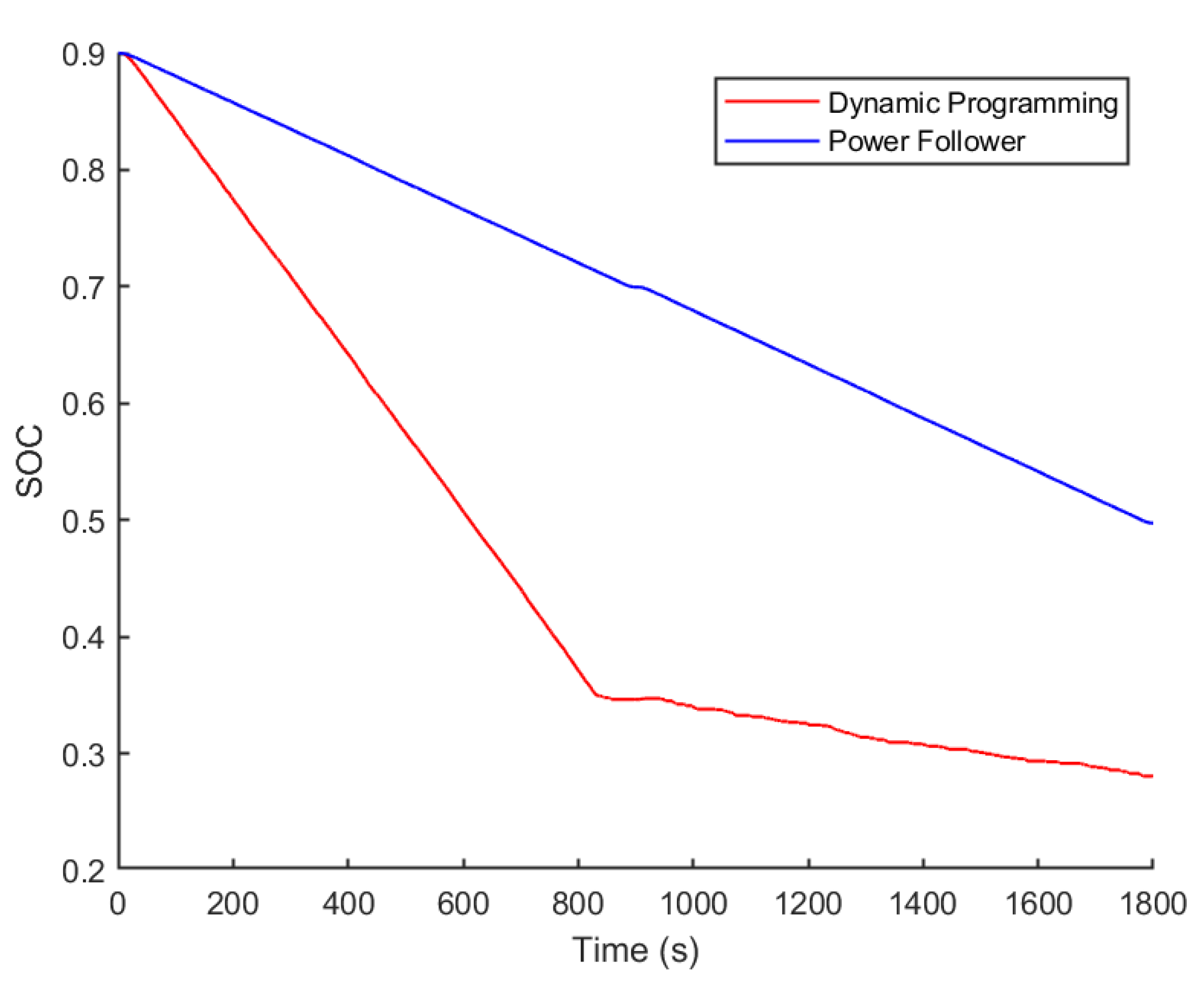
Figure 13. The state change of power battery SOC is shown in
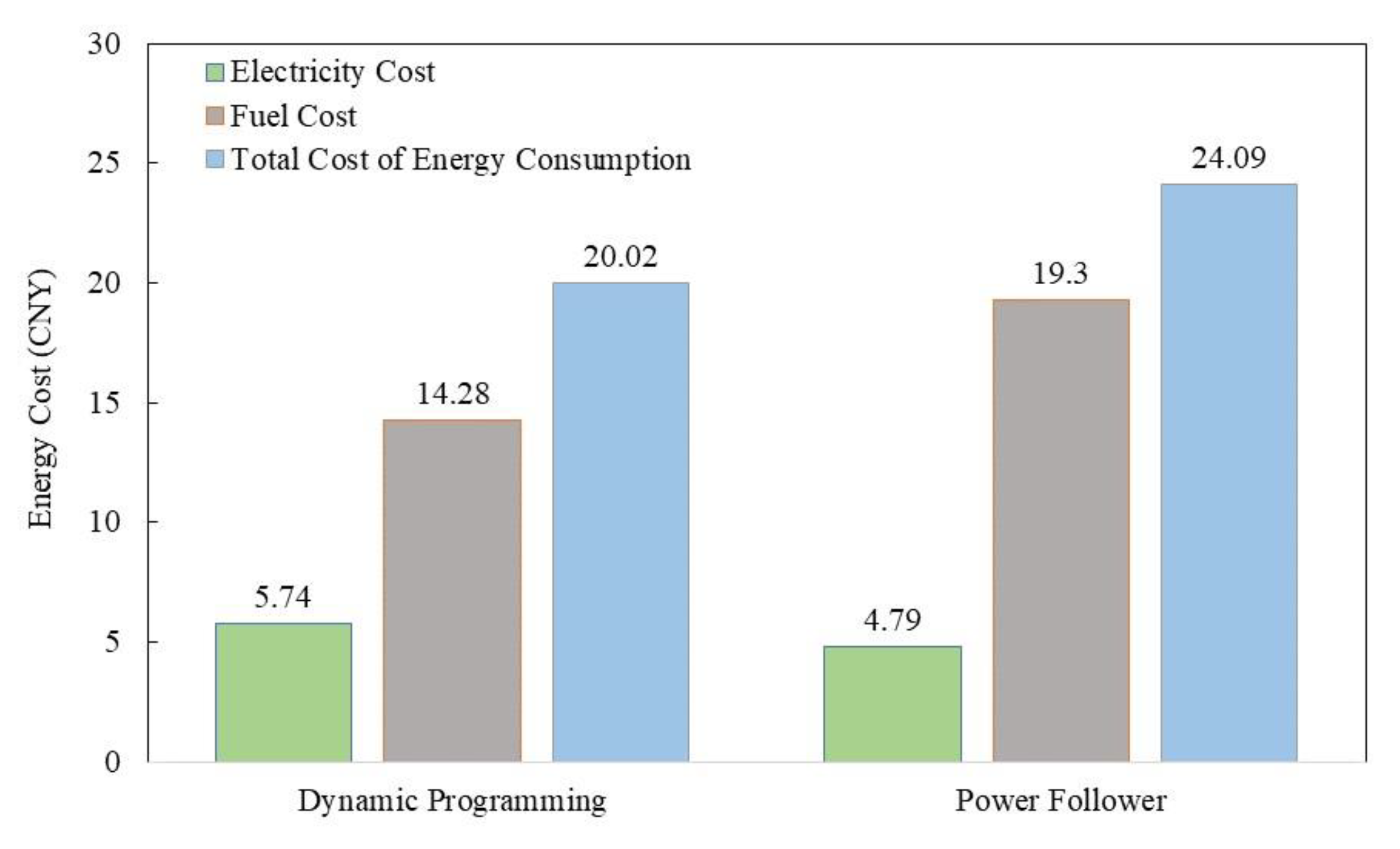
Figure 14. Energy costs are shown in
Figure 15.
From
Figure 13,
Figure 14 and
Figure 15, it can be known the CVT speed ratio is the same when the working speed is 0–3 km/h, but the CVT speed ratio is different when the working speed is 3–6 km/h under the two control strategies. Under the global optimization energy management strategy based on dynamic programming, the CVT speed ratio can not only change according to the working speed, but also make adjustments according to the required torque of the whole machine and the SOC value of the power battery. The SOC change trend of the two is basically the same, both showing a downward trend. Under the dynamic programming strategy, the SOC first drops rapidly to around 0.35, then fluctuates slowly, and some SOC rises. This corresponds to the negative torque part of the motor in
Figure 13. Under the power-following control strategy, the SOC has been decreasing without increasing. In the end, the total energy consumption cost of the global optimal energy management strategy is ¥ 20.02. The total energy consumption cost of the power-following energy management strategy is ¥ 24.09.
6. Conclusions
This study describes a globally optimized energy management for an agricultural hybrid tractor equipped with a CVT. Firstly, the motor torque and speed, diesel engine torque and speed, and CVT speed ratio are used as control variables, then the SOC for the power battery is used as the state variable, and minimize the total cost of energy consumption of the whole machine is the goal. Finally, an energy management strategy based on dynamic programming is designed.
To address the issue of low energy utilization efficiency in agricultural hybrid tractors, we propose a global optimal energy management approach based on dynamic programming. Taking a hybrid tractor as the research object, based on the topology structure of the hybrid tractor equipped with CVT, the simulation model of the main components is built. Then, the control simulation model is established by adopting MATLAB. Finally, the simulation test results are obtained. Through the analysis of the simulation results of the hybrid tractor rotary tillage working conditions, it can be obtained that the control strategy based on dynamic programming can be adjusted according to specific working conditions, and the working torque of the diesel engine and electric motor and CVT speed ratio can be reasonably allocated to make the electric motor and diesel engine work in a high-efficiency area. However, the control strategy based on power following can only distribute the torque of the motor and diesel engine according to the established rules, and cannot make corresponding torque distribution according to the working conditions. In the end, the total energy consumption cost of the power-following energy management strategy and the proposed strategy are ¥ 24.09 and ¥ 20.02, respectively. Compared with the power-following energy management strategy, the total energy consumption cost of the proposed strategy is decreased by 16.89%.
A dynamic programming control strategy is designed for the agricultural hybrid tractor with CVT, and the research shows that the strategy can significantly improve the energy consumption economy of tractor. It provides new ideas for the design and research of new energy agricultural tractors. At present, we have only studied the working conditions of tractor rotary tillage. In the future, we will study the plowing and transportation conditions of the tractor, and design a control strategy framework which may contain neuro-fuzzy that can meet multiple working conditions. Additionally, readers can further improve the energy consumption economy of the whole machine by optimizing the CVT speed ratio.
Author Contributions
Conceptualization, J.Z. and G.F.; methodology, L.X.; software, G.F.; validation, J.Z., G.F. and L.X.; formal analysis, M.L. and C.S.; investigation, M.L.; resources, L.X.; data curation, X.Y. and C.S.; writing—original draft preparation, G.F.; writing—review and editing, J.Z.; visualization, X.Y.; supervision, X.Y.; funding acquisition, L.X. All authors have read and agreed to the published version of the manuscript.
Funding
This research was funded by The National Key R&D Program of China (Grant Nos. 2022YFD2001203, 2022YFD2001201B), Key Scientific and Technological Research Projects in Henan Province (Grant No. 222102240088), Key Agricultural Core Technology Research Project (Grant No. NK202216010103), Open Project of State Key Laboratory of Intelligent Agricultural Power Equipment (Grant No. SKT2023001), and Open Project of State Key Laboratory of Tractor Power System (Grant No. SKT2022001).
Data Availability Statement
Not applicable.
Conflicts of Interest
The authors declare no conflict of interest.
References
- Fu, M.L. Characteristics of agricultural tractors emissions under real-world operating cycle. Trans. Chin. Soc. Agric. Mach. 2013, 29, 42–48. [Google Scholar]
- Yu, W.; Shen, X.; Wu, B.; Kong, L.; Xuan, K.; Zhao, C.; Cao, X.; Hao, X.; Li, X.; Zhang, H.; et al. Real-world emission characteristics of carbonyl compounds from agricultural machines based on a portable emission measurement system. J. Environ. Sci. 2023, 124, 846–859. [Google Scholar] [CrossRef]
- Moinfar, A.; Shahgholi, G.; Gilandeh, Y.A.; Gundoshmian, T.M. The effect of the tractor driving system on its performance and fuel consumption. Energy 2020, 202, 117803. [Google Scholar] [CrossRef]
- Liu, M.; Lei, S.; Zhao, J.; Meng, Z.; Zhao, C.; Xu, L. Review of development process and research status of electric tractors. Trans. Chin. Soc. Agric. Mach. 2022, 53, 348–364. [Google Scholar]
- Ghobadpour, A.; Mousazadeh, H.; Kelouwani, S.; Zioui, N.; Kandidayeni, M.; Boulon, L. An intelligent energy management strategy for an off-road plug-in hybrid electric tractor based on farm operation recognition. IET Electr. Syst. Transp. 2021, 11, 333–347. [Google Scholar] [CrossRef]
- Steven, B.; David, H. An overview of the hybrid and electric systems R&D at the U.S.–DOE (FY 2015–2016). World Electr. Veh. J. 2016, 8, 461. [Google Scholar]
- Mocera, F.; Somà, A. Analysis of a parallel hybrid electric tractor for agricultural applications. Energies 2020, 13, 3055. [Google Scholar] [CrossRef]
- Si, Y.; Qian, L.J.; Qiu, L.H.; Li, H. Energy management of a 4WD hybrid electric vehicle based on ECMS. China Mech. Eng. 2017, 28, 1112–1117. [Google Scholar]
- Li, T.; Cui, W.; Cui, N.X. Soft actor-critic algorithm-based energy management strategy for plug-in hybrid electric vehicle. World Electr. Veh. J. 2022, 13, 193. [Google Scholar] [CrossRef]
- Rohith, J.; Mahesha, G.T. Review of energy management strategies in plug-in hybrid-electric vehicles. In Flexible Electronics for Electric Vehicles; Springer Nature Singapore: Singapore, 2022; pp. 83–89. [Google Scholar]
- He, H.W.; Meng, X.F. A review on energy management technology of hybrid electric vehicles. Trans. Beijing Inst. Technol. 2022, 42, 773–783. [Google Scholar]
- Zhang, F.Q.; Hu, X.S.; Xu, K.H.; Tang, X.L.; Cui, Y.H. Status and prospects for model predictive energy management in hybrid electric vehicles. J. Mech. Eng. 2019, 55, 86–108. [Google Scholar] [CrossRef]
- Ma, D.B.; Zhu, F.T.; Gu, L.Q. Simulation on energy management strategy for four-wheel drive hybrid electric vehicle. Drive Syst. Tech. 2013, 27, 13–18. [Google Scholar]
- Ming, L.; Ying, Y.; Liang, L.; Yao, L.; Zhou, W. Energy management strategy of a plug-in parallel hybrid electric vehicle using fuzzy control. Energy Procedia 2017, 105, 2660–2665. [Google Scholar] [CrossRef]
- Luo, G.P.; Luo, Y.G.; Li, K.Q. Control strategy for plug-in hybrid electric bus based on optimal electric energy use. Automot. Eng. 2012, 34, 475–478. [Google Scholar]
- Gao, F.Y.; Zhang, H.R.; Wang, W.X.; Li, M.M. Energy management strategy of modern tram based on the combination of rule control and driving conditions. J. Mech. Eng. 2022, 58, 1–11. [Google Scholar]
- Geng, W.R.; Lou, D.M.; Zhang, T. Multi-objective Energy Management Strategy for Hybrid Electric Vehicle Based on Particle Swarm Optimization. J. Tongji Univ. (Nat. Sci.) 2020, 48, 1030–1039. [Google Scholar]
- Zhang, J.J.; Feng, G.H.; Xu, L.Y.; Yan, X.; Wang, W.; Liu, M. Energy-saving control of hybrid tractors based on instantaneous optimization. World Electr. Veh. J. 2023, 14, 27. [Google Scholar] [CrossRef]
- Chen, Z.; Mi, C.C.; Xia, B.; You, C. Energy management of power-split plug-in hybrid electric vehicles based on simulated annealing and pontryagin’s minimum principle. J. Power Sources 2014, 272, 160–168. [Google Scholar] [CrossRef]
- Li, W.; Wang, C.; Pei, H.; Xu, C.; Lin, G.; Deng, J.; Jiang, D.; Huang, Y. An improved energy management strategy of diesel-electric hybrid propulsion system based on FNN-DP strategy. Electronics. 2023, 12, 486. [Google Scholar] [CrossRef]
- Adeleke, O.P.; Li, Y.; Chen, Q.; Zhou, W.; Xu, X.; Cui, X. Torque distribution based on dynamic programming algorithm for four in-wheel motor drive electric vehicle considering energy efficiency optimization. World Electr. Veh. J. 2022, 13, 181. [Google Scholar] [CrossRef]
- Du, C.; Huang, S.; Jiang, Y.; Wu, D.; Li, Y. Optimization of energy management strategy for fuel cell hybrid electric vehicles based on dynamic programming. Energies 2022, 15, 4325. [Google Scholar] [CrossRef]
- Liu, C.N. Research on Management Strategy of Phev Based on Driving Condition Recognition and Multi-Objective Optimization; Shang Dong University: Jinan, China, 2022. [Google Scholar]
- Miao, Q.; Kong, F.M.; Shun, Q.; Bai, S.Z. Adaptive equivalent consumption minimization strategy based on dynamic programming. J. South China Univ. Technol. (Nat. Sci. Ed.) 2016, 44, 81–88. [Google Scholar]
- Xia, C.G.; Zhang, Y.; Shun, Y. Research on tractor speed control of hydraulic mechanical continuously variable transmission. Agric. Equip. Veh. Eng. 2022, 60, 22–26. [Google Scholar]
- Huazhong Agricultural University. Tractor Cars: Tractor Car Theory, 2nd ed.; China Agricultural Press: Beijing, China, 2001; pp. 89–97. [Google Scholar]
- Zhou, Z.L.; Ni, Q.; Xu, L.Y. Parallel hybrid tractor drive train parameter design and performance analysis. J. Henan Univ. Sci. Technol. (Nat. Sci.) 2016, 37, 9–15. [Google Scholar]
- Gao, S.H.; Chen, X.B.; Xue, J.; Gao, Q. Factor analysis of influencing factors of tractor operating resistance. J. Agric. Mech. Res. 2020, 42, 17–22. [Google Scholar]
- Bin, X.; Hao, L.; Zheng-He, S.; En-Rong, M. Powertrain system design of medium-sized hybrid electric tractor. Inf. Technol. J. 2013, 12, 7228–7233. [Google Scholar] [CrossRef]
- Liu, M.N.; Xu, L.Y.; Zhou, Z.L.; Liu, W.G. Establishment of extended range electric tractor and its rotary cultivator’s simulative platforms. China Mech. Eng. 2016, 27, 413–419. [Google Scholar]
- Likhanov, V.A.; Anfilatov, A.A. Mathematical model of the formation and burning of smoke. IOP Conf. Ser. Mater. Sci. Eng. 2020, 862, 032–050. [Google Scholar] [CrossRef]
- Wang, S.Q. Research on Online Energy Management Control Strategy of Phev Based on Global Optimization of Equivalent Factors; Chong Qing University: Chongqing, China, 2021. [Google Scholar]
- Li, S.G.; Sharkh, S.M.; Walsh, F.C.; Zhang, C.N. Energy and battery management of a plug-in series hybrid electric vehicle using fuzzy logic. IEEE Trans. Veh. Technol. 2011, 60, 3571–3585. [Google Scholar] [CrossRef]
| Disclaimer/Publisher’s Note: The statements, opinions and data contained in all publications are solely those of the individual author(s) and contributor(s) and not of MDPI and/or the editor(s). MDPI and/or the editor(s) disclaim responsibility for any injury to people or property resulting from any ideas, methods, instructions or products referred to in the content. |
© 2023 by the authors. Licensee MDPI, Basel, Switzerland. This article is an open access article distributed under the terms and conditions of the Creative Commons Attribution (CC BY) license (https://creativecommons.org/licenses/by/4.0/).


