Article

A System for the Efficient Charging of EV Fleets

1
SAP Deutschland, 69190 Walldorf, Germany
2
Data-Centric Software Systems (DSS) Research Group, Institute of Applied Research (IAF), Karlsruhe University of Applied Sciences, 76133 Karlsruhe, Germany
*
Author to whom correspondence should be addressed.
These authors contributed equally to this work.
World Electr. Veh. J. 2023, 14(12), 335; https://doi.org/10.3390/wevj14120335
Submission received: 18 October 2023 / Revised: 17 November 2023 / Accepted: 21 November 2023 / Published: 2 December 2023

Abstract

:
Smart charging is a means of monitoring and actively controlling EV chargers to optimize the distribution and consumption of energy with a focus on peak-load avoidance. This paper describes the most important requirements that have influenced the design and implementation of the “Smart Charging System” (SCS). It presents the architecture and main functional building blocks of the SCS, which have been realized in an iterative development process as an extension component of the already existing open-source solution “Open e-Mobility”. We also provide details on the functionality of the core smart charging algorithm within SCS and show how various data sources can be utilized by the system to increase the safety and efficiency of EV charging processes. Furthermore, we describe our iterative approach to developing the system, introduce the real-world testbed at SAP Labs France in Mougins/France, and share evaluation results and experiences gathered over a three-year period.

1. Introduction

In the past decade, the global market share of electric vehicles (EV) has been growing rapidly. A significant proportion of EVs of all types, including cars, delivery vans, trucks, buses, etc., belong to corporate fleets. For example, in Germany 58% of all electric cars sold in 2021 were registered to companies [1]. Companies are increasingly using their EV fleets for business-related and sometimes even mission-critical purposes as EVs prove to be more and more reliable. To ensure the high operational readiness of EVs and reduce dependency on publicly accessible charging stations, many companies build and operate their own EV charging infrastructure (CI) on their premises. Those facilities are also often used by employees to charge privately owned EVs at work. Establishing and operating a CI poses a number of economic challenges to a company, including high capital and operating costs (TCO), volatile and less predictable utilization (during and outside business hours), complex tax regulations, etc. [2,3,4]. In addition, businesses must take several technical boundaries at typical parking areas into consideration, such as missing or insufficient cabling, grid power limitations, bad network connectivity, etc. A properly designed software system can help enterprises master many of the operational challenges during the entire life cycle of charging stations and other related assets. A crucial task thereby is to optimize the distribution of available and in many cases limited amount of power among multiple, often heterogeneous EVs and chargers in a safe and cost-efficient manner. Smart charging algorithms can also help increase driver satisfaction by maximizing the average state of charge (SoC) across multiple simultaneously charged EVs at a given location [5]. In addition, ref. [3] shows that an intelligent charging strategy can almost double the utilization of the infrastructure and the available power compared to an uncontrolled baseline charging strategy. Further related work in the research area of smart charging is summarized in various studies. For example, ref. [6] reviewed seven case studies related to smart charging. In the context of commercial EV fleets, ref. [7] identified challenges in return-to-base scenarios. A comprehensive overview of smart charging applications together with an overview of publicly known pilot projects is provided in [8]. Case studies often include real-world testing in technically limited environments with a very small number of EVs. For example, in [9], a possible design of charging infrastructure for company locations is presented while considering charging preferences and trip data of a bakery in Germany. A three-day experiment in a so-called “mobility house” (containing student housing, a grocery store, and a parking garage) showed that rule-based peak shaving and load demand forecasting can reduce load demand peaks by 25.4–38.5% while ensuring a minimum SoC of 50% [10]. The applicability of smart charging approaches that were designed specifically for charge-at-work scenarios, such as [11,12], and various related scheduling strategies, e.g., refs. [13,14,15,16,17] are usually evaluated in simulations rather than operational environments. The same holds for [4], which proposed a charging simulation model to support the design of a corporate charging infrastructure based on employees’ driving data. Further challenges in the context of scheduling charging processes and related requirements for a software system are presented by [2]. Other operational challenges that require the usage of additional hardware, e.g., to recognize vehicles that are not connected to the system (e.g., unplugged EVs, conventional vehicles that block EV parking lots, etc.), are not in the scope of our work. An approach to deal with such problems can be the integration of sensors, such as LiDAR systems, and related data platforms that help connected automated vehicles detect and handle certain situations, including searching suitable parking lots [18,19].
In this paper, we present the Smart Charging System (SCS), which is a software system mainly designed to serve companies that operate EV fleets and have one or more parking areas at their sites equipped with charging stations. In contrast to the above-mentioned research, our smart charging approach and system implementation has been deployed and actively used to power a large number of EVs in resource-constrained environments. Research results are often validated with the help of simulations, because research institutions usually do not operate EV fleets and EV fleet operators do not provide researchers with access to their business facilities and data. Nevertheless, simulation is a useful instrument, for example, to initially test new features or the applicability of system improvements before putting those into operation. The same holds for pilot projects, which usually only run for a limited time with a small number of EVs in a lab environment (e.g., known vehicle properties, selected hardware, controllable user behaviour). The findings presented in this work are based on the iterative implementation process and evaluation in a real-world testbed. We discuss requirements and approaches to fulfil them with the help of our SCS, such as dealing with missing data, connectivity issues, etc., in the real-world, which are usually not covered in smaller test scenarios or in theoretical research backed by simulations. Technically, the SCS is an optional extension component of the open-source system “Open e-Mobility” (OE) [20]. OE is currently used to manage thousands of charging stations at different locations of various companies. It can be deployed and operated as an on-premises system or as a containerized cloud solution and communicate with several other systems via the provided interfaces. The deployment and activation of the presented SCS within an OE instance helps manage energy distribution, infrastructure protection, and other related other requirements in an automated manner. Without activating the SCS in an OE system, related tasks must be carried out by the operator, who manually enters power limits for each charging point (CP), for example. The remainder of the paper is organized as follows: In Section 2, we describe our iterative approach to develop the software system, summarize the identified main functional and non-functional requirements, and introduce the real-world testbed at SAP Labs France in Mougins (France) that was used for technical evaluation. In Section 3, we present the architecture and main functional building blocks of the SCS, explain the functionality of the core EV charging algorithm, and show its integration with various data sources that are supported in the current implementation. We also discuss particular advantages of the incrementally added features and data sources that helped increase the efficiency of the charging infrastructure. Finally, we draw conclusions and outline directions for our future work in Section 4.

2. Materials and Methods

2.1. Iterative Software Development Approach

The SCS, along with other software components of OE, was realized and tested in multiple iterations in a period of three years. The development process included multiple phases and related test cycles. In each development phase, a new, encapsulated and independent component was added to the already existing SCS so that respective improvements were feasible and measurable. When designing and implementing the SCS, we focused in particular on the following capabilities as main requirements for the system:
  • Infrastructure protection: During the simultaneous charging of EVs, huge demand peaks can occur, damaging the infrastructure or even leading to outages. The SCS must deal with several related thresholds at the same time, such as the mains connection power of the site, limitations of the local electrical infrastructure according to fuse hierarchies, capacity of individual power lines and transformers, etc. In addition, it is important to communicate with the local energy management system (EMS), if deployed on site, to quickly react on fluctuations of the available power caused by electricity consuming devices (e.g., machinery, HVAC devices) or by energy producing assets (e.g., PV, CHP).
  • Management of heterogeneous charging equipment: A company’s CI can contain AC and DC chargers of various vendors, types and versions. Considering only “abstracted” equipment in the software system can lead to severe problems, because “real” devices behave differently with respect to their, e.g., charging curve characteristics, in/output ratios, means of data provisioning, interfaces, configurable parameters, etc. The larger the CI, the greater the cumulative effect of these factors can be.
  • Support of EV-specific charging: During a charging session, the EV’s battery management system may autonomously increase (or lower) the demanded power. As a reaction, the SCS may limit the maximum available power or provide the EV with additional power, e.g., by rescheduling other EVs’ charging sessions. Accordingly, the SCS requires up-to-date information about connected vehicles, including the maximum allowed current/power, number of phases used, etc.
  • Context-aware prioritization: In the business context, a prioritization of charging sessions is often needed: A salesperson, who wants to visit a customer and needs a “full” battery within two hours, has higher priority than another employee, who leaves the office at the evening. To determine prioritization, data items from different sources are required, e.g., planned arrival time, estimated departure time, capacity of EV batteries, current SoC, etc.
  • Interoperability and scalability: The SCS must seamlessly interact with other system components over available interfaces and network protocols. It should also be able to serve CIs of different size and allow adding (removing) locations to the overall setup.
  • Flexibility: CI sites have different properties and characteristics, for example, with regard to the number and type of served EVs, usual charging times, local infrastructure limitations, etc. Consequently, the structure and operational complexity of the SCS also varies between deployment sites. In order to address this, the SCS needs to be built to be modular and thus adaptable to the given infrastructure, EV fleet, user needs, and prioritization requirements. In general, the SCS must be able to work in different complexity levels and enable adding/removing components independently from each other.
  • Exception handling: In case of errors, e.g., due to malfunctioning charging stations or EVs, a proper exception handling in near real time is needed. Thereby, vendor- and device-specific error messages must be captured and properly interpreted. It must also be ensured that failing or bad network connectivity (HTTP, WebSocket, TCP/IP) does not jeopardize running charging sessions and missing data are handled when planning new sessions. If there is an outage in the local electrical system, a safe restart of charging procedures is required.

2.2. Method of System Evaluation

The evaluation of the system in an operative environment took place at the premises of SAP Labs France in Mougins, France. The charging infrastructure on site has been initially set up and maintained by local team members. Experiments with the SCS began on 1 April 2020, which was a good time to start, because the local CI was less stressed as usual (due to COVID-19) and users were therefore more tolerant of potential technical problems. As time went on, the number of both charging stations and charging operations increased steadily, so that the scalability of the system could be tested as well. The testbed currently comprises 38 charging points (31 AC and 7 DC) at 22 charging stations of different vendors, including Schneider Electric, Legrand, ABB, Delta, IES, Webasto, Ebee, Mennekes, Keba, StarCharge, Wall Box Chargers, and Joinon. In the evaluation period, the system served in total over 650 employees to charge 291 company cars of various vendors including Tesla, Jaguar, Kia, Renault, Volkswagen, Audi, Mercedes, Hyundai, BMW, Fiat, Volvo, and Nissan. In total, more than 25,000 EV charging sessions were executed successfully, consuming approximately 700 MWh energy with a combined session time of almost 3400 days. The system protected the power-constrained infrastructure well since it never experienced critical overload situations throughout the entire test period. In addition to the real-world tests, a tool [21] that simulates the behaviour of multiple OCPP-compliant charging points was also used to frequently test SCS. It especially helped avoid technical and safety-related problems that would have been occurred due to errors (bugs) in the software implementation.

3. Results and Discussion
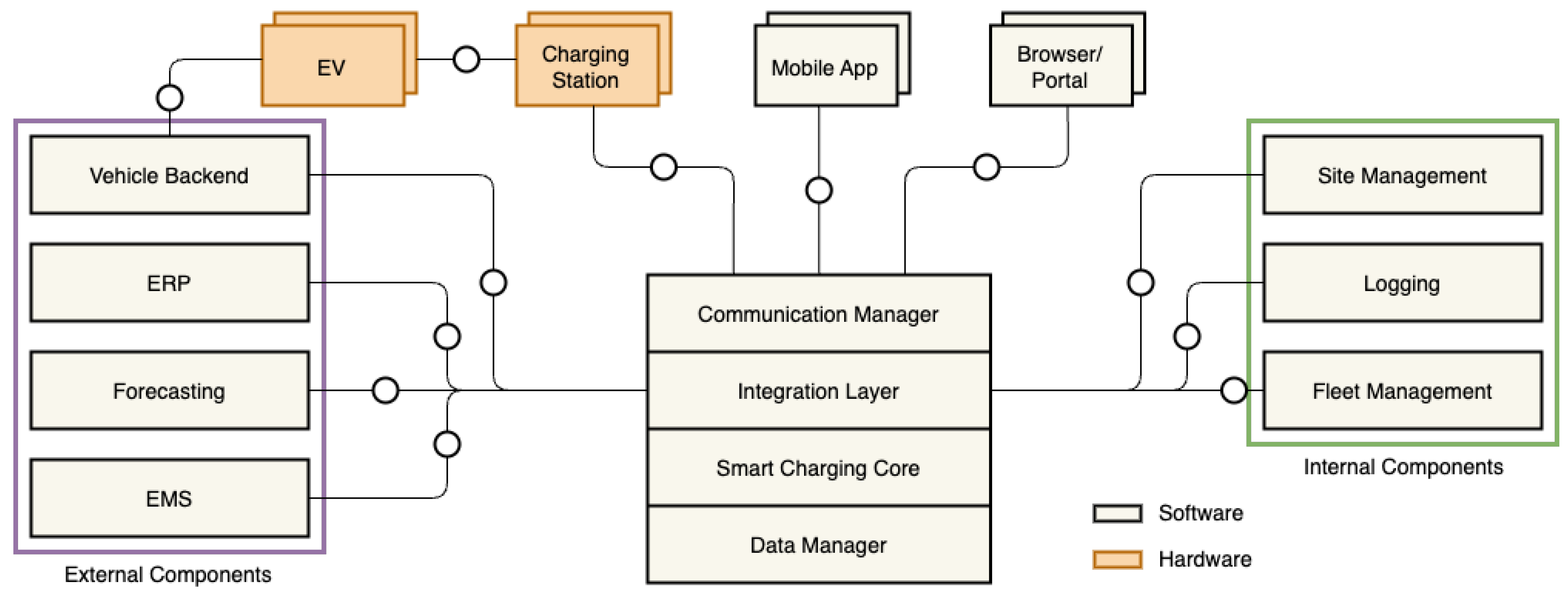
3.1. System Design

The high-level architecture of the SCS contains four main functional components as shown in Figure 1. The main task of the component Smart Charging Core is to calculate and dynamically adjust the distribution of available power among the active charging sessions in the given CI (see details in Section 3.2). The Data Manager stores permanent data, such as the system configuration and master data about the capabilities of the installed charging stations. It also maintains temporary information needed to carry out calculations, for example. As part of OE, the SCS interacts with other components of the entire charging-point management system, termed as “Internal Components” in Figure 1. For instance, the SCS logs relevant technical events using the Logging interface of OE. The SCS also provides information about the status of active charging sessions for EV drivers via the Mobile App as well as for the CI’s technical operator via Browser/Portal. The SCS can communicate and exchange data with further “External Components”, including EMS, enterprise resource planning (ERP) or EV vendors’ Vehicle Backend, if they are available and made accessible within the CI owner’s IT environment. These external systems are mainly used by the SCS as data sources to support ongoing calculations of charging plans. The required connections to these systems and charging stations on site, including protocol- and API-specific messaging, are handled by the Communication Manager. The component Integration Layer is mainly responsible for collecting the required data from the different connected sources in a synchronous or asynchronous way, and also for the preparation of the gathered data for further processing by the core component (see details in Section 3.3).
The deployment of the four main components, i.e., without the above-mentioned additional data sources, is sufficient to operate the SCS with basic functionality. In this case, the Smart Charging Core can work with predefined configuration values, such as fixed safety limits for power consumption, and it does not take into account dynamic information, such as instantaneous solar power generation. The above-mentioned additional internal and external components can be added (activated) optionally and independently from each other helping to adapt the SCS to specific requirements in the given scenario.

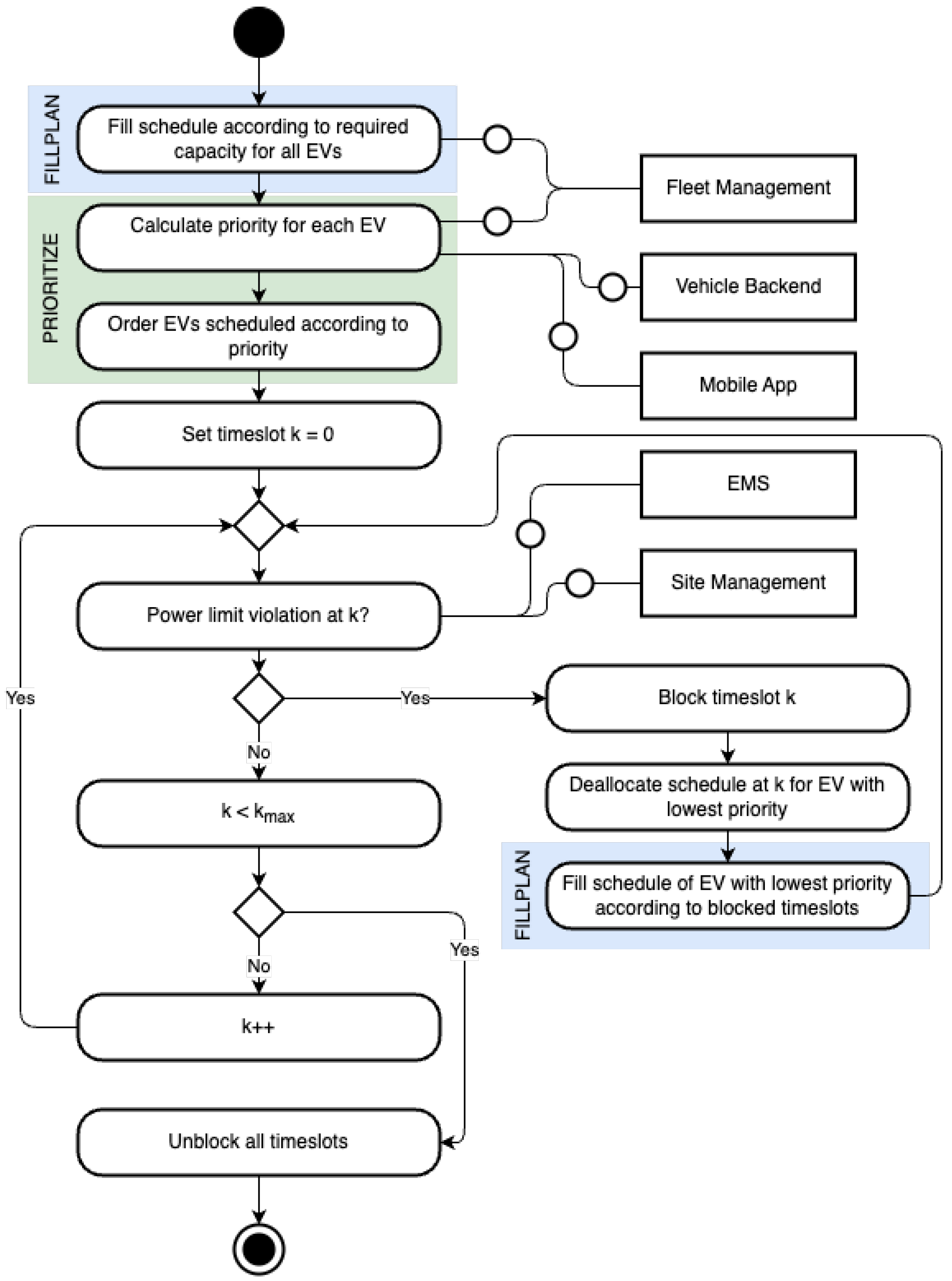
3.2. Smart Charging Core

The current version of the SCS implements a scheduling procedure illustrated by the flowchart in Figure 2. The initial concept is presented in [13,22], and the corresponding implementation is available online on GitHub [23]. The main goal of the overall process (see also the pseudo-code in Algorithm 1) is to share the basically limited charging power at a given location among the connected EVs in a fair manner. The SCS triggers the calculation when a new charging session starts to meet the additional demand, or when an ongoing session ends to redistribute the released capacity. The scheduling procedure can also be executed periodically (e.g., every 15 min) to adjust the power consumption of ongoing sessions, as well as on demand, when significant changes in the amount of available energy are detected (e.g., through additional solar production). The output of the calculation is a charging plan that determines which of the connected EVs should receive power in the next k time slots without violating the local site’s safety limits (see also Algorithm 2 for details). During charging plan creation, EVs can be prioritized (using Algorithm 3), which is especially useful when the total (aggregated) power demand would exceed the maximum available power in one or more time slots. As shown in Figure 2 several optional data sources (represented as rectangles) can be utilized during the calculation in order to adapt the system’s behaviour. It is important to note that the scheduling process is able to work without receiving data from those sources, e.g., due to a technical problem. For example, in case the actual battery type and capacity of a plugged-in EV is unknown because the Fleet Management component is temporarily unavailable, the SCS can run using preset values.
Algorithm 1 Scheduling procedure
1:
procedure SCHEDULE( e v L i s t , t s L i s t )
2:
    for  i 1 to e v L i s t . l e n g t h  do
3:
        FILLPLAN( e v [ i ] , t s L i s t )                ▷ Algorithm 2 called
4:
    end for
5:
    PRIORITIZE( e v L i s t )                     ▷ Algorithm 3 called
6:
    for  k 1 to t s L i s t . l e n g t h  do
7:
         s u m I t s 0
8:
          for  i 1 to e v L i s t . l e n g t h  do
9:
            s u m I t s s u m I t s + e v L i s t [ i ] . t s L i s t [ k ] . I
10:
        end for
11:
         i n d e x 1
12:
        while  s u m I t s fuse limit do      ▷ Check if total current exceeds limit
13:
            t s L i s t [ k ] b l o c k e d            ▷ Block time slot for rescheduling
14:
            s u m I t s s u m I t s e v L i s t [ i n d e x ] . t s L i s t [ k ] . I
15:
           FILLPLAN( e v L i s t [ i n d e x ] , t s L i s t )     ▷ Reschedule EV with lowest priority
16:
            i n d e x + +
17:
        end while
18:
    end for
19:
end procedure
Algorithm 2 Procedure to fill EV charge plans
1:
procedure FILLPLAN( e v , t s L i s t )
2:
    for  k 1 to t s L i s t . l e n g t h  do
3:
        if  t s L i s t [ k ]  not  b l o c k e d e v . c a p i n i t + e v . c a p c h a ( k ) e v . c a p m a x  then
4:
            e v . t s L i s t [ k ] . I m i n ( e v . I m a x , c p . I m a x )    ▷ Assign lower value of CP/EV max current
5:
        else
6:
              e v . t s L i s t [ k ] . I 0
7:
        end if
8:
    end for
9:
end procedure
Algorithm 3 Prioritization procedure
1:
procedure PRIORITIZE( e v L i s t )
2:
    for  i 1 to e v L i s t . l e n g t h  do
3:
         m C a p m i n S o C e v L i s t [ i ] . c a p d e s ( e v L i s t [ i ] . c a p i n i t + e v L i s t [ i ] . c a p c h a )
4:
         Δ t e v L i s t [ i ] . t d e p e v L i s t [ i ] . t n o w
5:
        if  m C a p m i n S o C 0  then  ▷ Assign higher priority if EV is below minimum SoC
6:
            e v L i s t [ i ] . p r i o r i t y m C a p m i n S o C / ( ( Δ t * e v L i s t [ i ] . I m a x ) + 1 e 8 )
7:
        else
8:
            m C a p m a x S o C e v L i s t [ i ] . c a p m a x ( e v L i s t [ i ] . c a p i n i t + e v L i s t [ i ] . c a p c h a )
9:
            e v L i s t [ i ] . p r i o r i t y m C a p m a x S o C / ( ( Δ t e v L i s t [ i ] . I m a x ) + 1 e 8 ) 1000
10:
       end if
11:
    end for
12:
    sort  ( e v L i s t , p r i o r i t y )                ▷ Sort according priority
13:
    return
14:
end procedure
The scheduling algorithm (see Algorithm 1) initially creates a “greedy” charging plan for each e v in e v L i s t for n time slots of duration d represented in t s L i s t . In a practical setup, for example, with n = 96 and d = 0.25 hours, a charging plan for the next 24 h can be created.
By executing Algorithm 2 for each EV (see Lines 2–4 in Algorithm 1), the maximum possible charging current will be assigned to each EV, according to the limitations of the given EV ( e v . I m a x ) and the charging point ( c p . I m a x ).
This is repeated for the next time slots until the sum of the EV’s initial charge capacity e v . c a p i n i t (measured in Ah) and charged capacity e v . c a p c h a reaches/exceeds the battery’s maximum capacity e v . c a p m a x . Note that e v . c a p c h a is calculated based on the charging current I assigned to the EV and the total duration of passed k time slots.
To face potential conflicts that could occur if the total scheduled charging power within one or more time slots exceeds power limitations of the charging infrastructure, some EVs’ initially created charging plans must be adjusted, i.e., delayed. For that purpose, EVs are ranked by executing Algorithm 3 (see Line 5 in Algorithm 1). In order to determine the critical time slots, s u m I t s , the sum of charging currents assigned to all EVs in e v L i s t in each time slot, is calculated. A particular time slot will be b l o c k e d (see Line 13 in Algorithm 1) if the resulting value is not below the relevant technical limitation of the charging site’s electrical system (called fuse limit). The s u m I t s is reduced by the previously given charging current I of the lowest ranked EV (see Line 14 in Algorithm 1), whose charging plan will be refilled. Afterwards, the EV with the lowest priority is rescheduled by applying Algorithm 2 (see line 15 in Algorithm 1). Reducing the charging current to zero in all blocked time slots (see Line 6 in Algorithm 2) leads to a delayed/prolonged charging of the particular EV, because the intended c a p m a x value cannot be reached otherwise. This shifting procedure is repeated for the next ranked EVs until the violation of the fuse limit within the time slot is solved. Note that an adjustment of the charging current in the last unblocked time slot to match fuse limits more exactly is implemented but not included in the pseudo-code due to readability and space reasons.
The aforementioned prioritization of EVs for being potentially rescheduled is performed in Algorithm 3. To rank EVs in e v L i s t , the missing capacity to reach the minimum SoC m C a p m i n S o C (measured in Ah) is calculated for each EV. This is the difference between the EV’s desired charge capacity c a p d e s (calculated from the desired SoC, in %, as entered by the user) and the sum of its initial capacity c a p i n i t on arrival and the capacity charged c a p c h a since then (see Line 3 in Algorithm 3). The urgency of charging depends on the available time Δ t between departure time t d e p (e.g., entered by the EV driver) and current time t n o w . If the minimum SoC is not yet reached, the priority is calculated based on m C a p m i n S o C , the urgency Δ t , and the maximum charging current I m a x of the EV (see Line 6 in Algorithm 3). The applied formula basically ensures that EVs/drivers with higher energy demand and less time for charging will receive a higher priority in average and thus will not be taken as first candidates for being “shifted”. The other EVs that already reached their minimum expected SoC will be ranked based on the charge capacity that is missing to reach the maximum capacity of the vehicle’s battery m C a p m a x S o C . The chosen formula (see Line 9 in Algorithm 3) gives in average a higher rank for those EVs with higher energy demand and less available time to fully charge their batteries. Accordingly, first candidates for rescheduling will be those EVs that almost reached their batteries’ maximum capacity and still have time to wait.

3.3. Integration Layer

To leverage the capabilities of the generic Smart Charging Core component and to configure the implemented algorithms properly, information from several heterogeneous data sources with regard to, e.g., available APIs, security settings, data formats, etc., must be gathered. In case these sources are not deployed in the given environment and/or (temporarily) unavailable, the algorithms must be provided with preset values to ensure operational safety at any point in time. Similarly, a calculated charging plan must be transmitted to all connected charging stations and the respective EVs, so that they can interpret received messages (commands) and set configuration parameters or return data as requested. These data-oriented tasks are carried out by the Integration Layer. This component basically allows the adaptation of the Smart Charging Core to the given context and operational environment. Note that the SCS currently supports Open Charge Point Protocol (OCPP) version 1.6 [24]. Accordingly, the Integration Layer creates and maintains a charging profile for each connected, OCPP-compatible charging station within the CI. A fundamental task thereby is to handle misbehaving or incompatible charging stations. For that purpose, the Integration Layer monitors and reflects the current status of the CI, and it reacts on events that occurred. It can also collect data on ongoing charging sessions in near real time and help redistribute the available power according to the actual power consumption of ongoing sessions. Below, the tasks and functionality of the Integration Layer are explained in more detail.
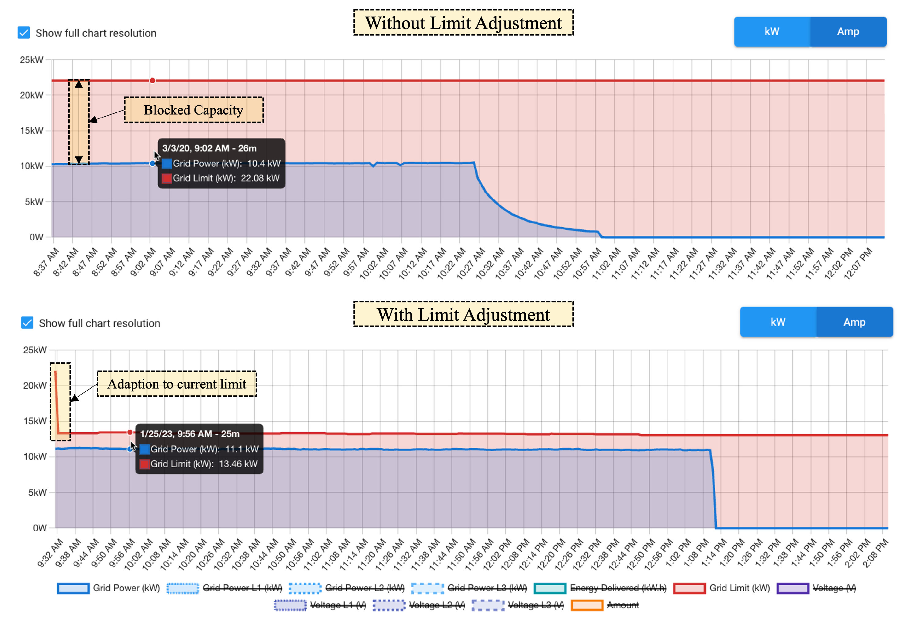
  • Error and Exception Handling: The SCS presupposes a proper implementation of OCPP by the charging stations and the support of OCPP charging profiles. However, OCPP implementations vary by charging station manufacturer and model. Compatibility problems often appear in specific setups and cases, which were not known upfront. The Integration Layer offers different mechanisms to master such situations. When collecting data to properly configure the core scheduling algorithm, the capabilities of connected stations are checked. It is especially examined whether each station is able to work with the generated OCPP profiles. If not, the given charging station will be excluded from the optimization, because it cannot be limited. In order to not endanger the electrical infrastructure, the SCS will automatically adjust infrastructure limits for the next optimization cycles by subtracting the maximum power that the incompatible station can draw. The adjustment of these limits only happens if the affected charging station is charging. Otherwise, the full capacity can be considered by the optimization. A similar mechanism is applied if a charging station is rejecting or not answering to charging profile requests, e.g., due to network issues. In this case, the faulty stations are collected and handled as incompatible charging stations in a separate optimization cycle. At the same time, a notification framework informs the administrators about the stations, which are not working correctly in order to take action if the issue persists.
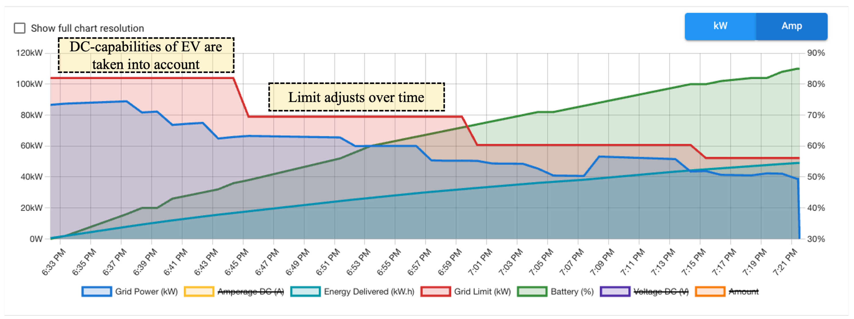
  • AC/DC Handling: The Integration Layer supports both AC and DC charging sessions according to their specifics. AC sessions can use one, two, or all three phases depending on the given charging station and connected EV. When triggering the Smart Charging Core, this information must be taken into account to determine the demanded charging current per phase. DC stations usually use all three phases, which makes phase assignments redundant. For DC chargers, however, the efficiency values need to be taken into account because the conversion from AC to DC is carried out by the charging station and not by the EV (as in case of AC chargers).
  • Vendor-specific handling: Charging station vendors tend to vary in how they handle OCPP charging profiles, for example, by using their preferred measurement units (kW or Ampere). Therefore, the Integration Layer provides a framework and mechanism to adapt a generic charging profile template to vendor specific requirements.
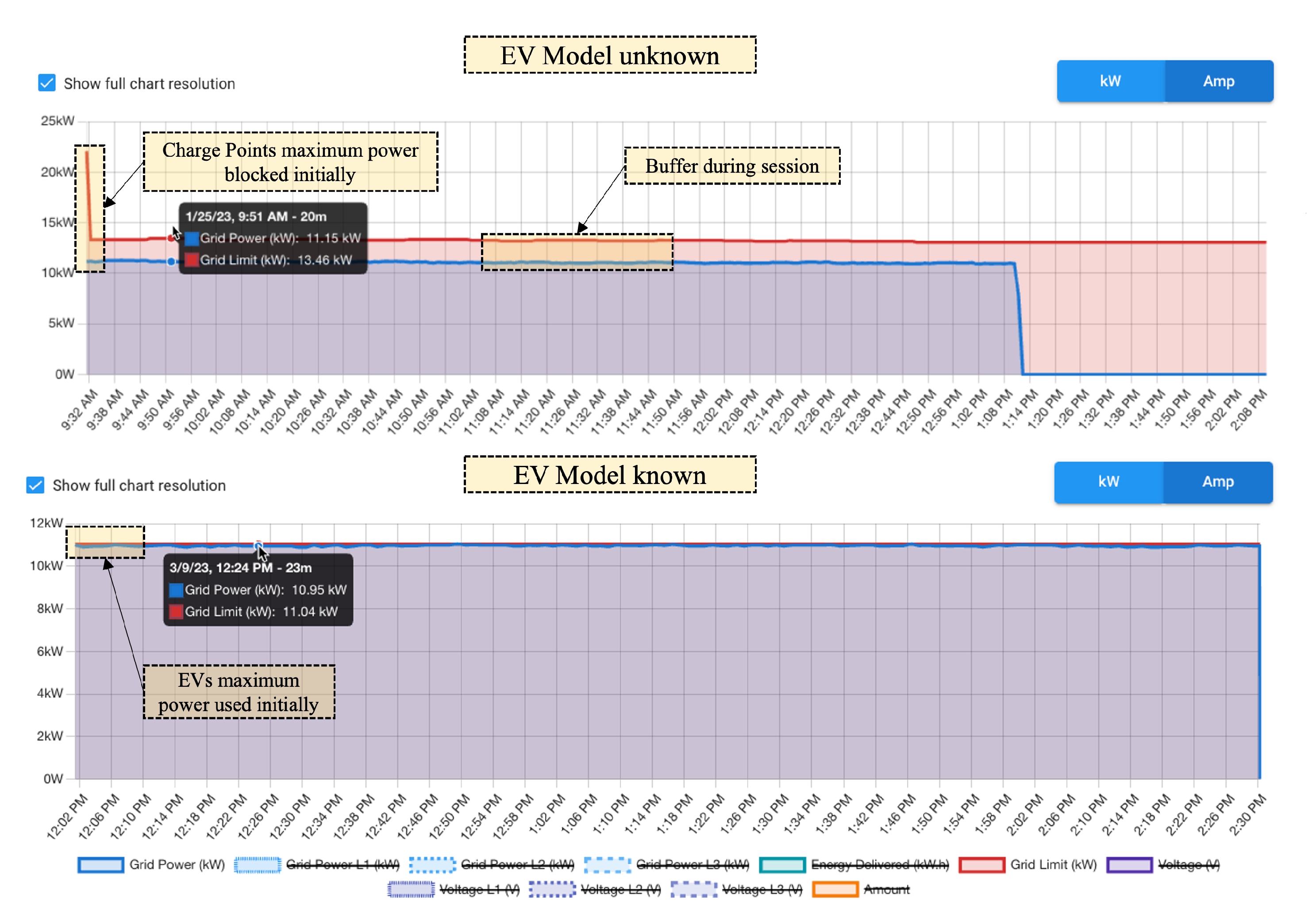
  • EV-specific handling: With the help of the Fleet Management component, the SCS is able to retrieve data about converters and batteries of almost every EV-model on the market, by using the Electric Vehicle Database [25] and other similar repositories. To keep the vehicle data up to date, synchronization jobs with the respective data sources are implemented. The data can be used to instantiate vehicles of a certain type in Fleet Management. By assigning these vehicles to users, the system can determine which EV model is charging at which station, without the need to establish a communication channel to the EV itself. The extracted information (converter data, battery size) is used to send power limits and battery capacities to the Smart Charging Core instead of waiting for actual monitored consumption data and adopting power limits later. In addition, the system provides implementations of service interfaces offered by OEMs, such as Mercedes, and also by third-party service platforms, like Tronity, to receive live information about the current state of charge during AC sessions. The stored data of the EVs are extended with this information and can be provided for different purposes such as priority handling.
  • Real-time behaviour adaptation: The process of EV charging (both AC and DC) can be influenced by many factors. The charging curve, i.e., the power drawn over time, depends not only on the type, age, and condition of the hardware on the vehicle side but also on external parameters, such as temperature. In some cases, significant deviations from the expected model-specific behaviour can be observed when charging a particular EV. A negative implication can be that EVs consume less power than expected and thus allocated to the session when it started. DC chargers especially manage power usage actively by monitoring the connected battery’s charging status. An efficient charging system must react to such varying (in general, unpredictable) power curves. The Integration Layer captures the momentary power drawn in the charging sessions and supports the SCS in calculating the real charge demand of a particular vehicle. The implemented mechanism puts a buffer on top of the observed power output of the charging station and uses the increased value as a new power limit for the session, whereby the new limit remains below the connector’s maximum limit. By supervising whether the EV uses the buffer, the algorithm can determine if the car would be able to draw more power and provide it to the session if available. This way, it is also ensured that incorrect or missing vehicle data does not lead to the allocation of later unused power capacity.
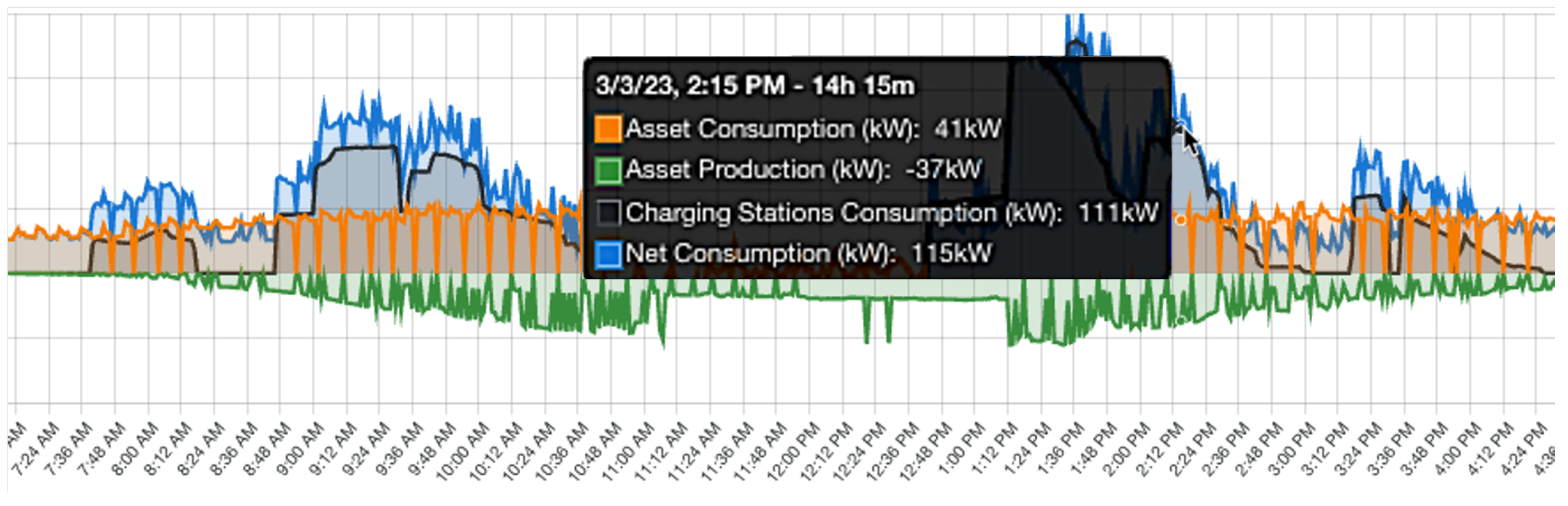
  • Dynamic power limits: In most cases, charging stations are operated in combination with other energy consuming or producing devices. The amount of demanded and produced power within an electrical system can heavily vary depending on season, time of the day, temperature, weather, etc. Setting a fixed, safety-oriented power limit for the CI could make it basically independent from the fluctuations but lead to lower throughput and efficiency. For this reason, the SCS can be integrated with external EMS that monitors and controls the overall electrical infrastructure on site. This integration should be as flexible as possible, to support as many EMS providers as possible. Thus, the SCS provides an API endpoint to push energy data, but also integrates with external APIs to pull/request data from. By taking into account EMS data, it is possible to dynamically adapt the available power for the CI according to the current solar production, building consumption, etc.
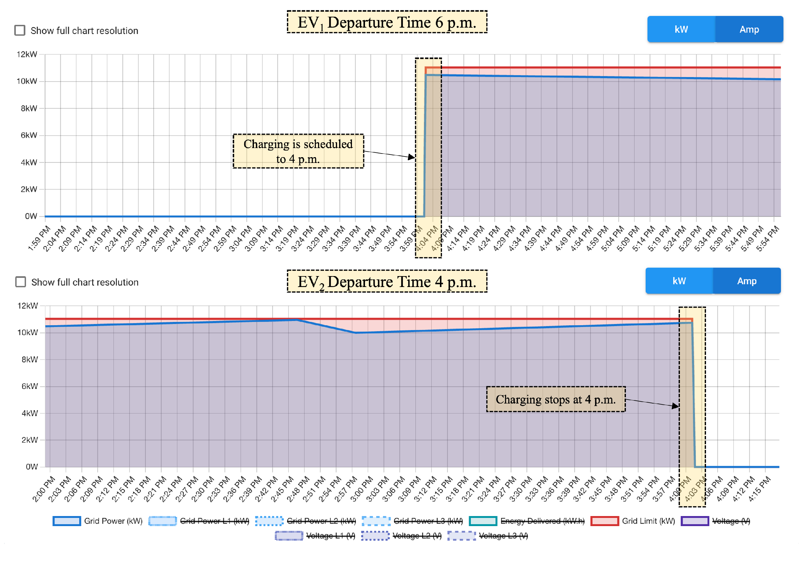
  • Priority Handling: To support the prioritization of EVs (as shown in Algorithm 3) and related charging sessions, the SCS collects as much information as possible. For instance, the Mobile App provides a dialogue for the driver to enter their planned departure time, required state of charge, and also the current state of charge (if the data are not provided by another integrated source or service). After the data are collected, they are processed and passed to the Smart Charging Core, which uses the received parameters to determine which EVs are prioritized and can thus charge faster. This ensures a fair sharing of power among trustworthy EV drivers and helps minimize inactivity times.

3.4. Implementation and Deployment in a Real-World Testbed

The SCS was implemented using TypeScript as programming language and the NodeJS runtime, which are utilised by other OE components as well. The integration with components of the existing OE was carried out in accordance with the programming guidelines of the overall project. To integrate optional, encapsulated components, OE uses a feature-oriented approach and a Component Manager. It enables the selection and individual activation, deactivation and configuration of certain functional artefacts in a flexible manner [26]. An example for such an optional feature in the context of OE is the roaming functionality, which can be switched on or off according to end users’ requirements. The flexible combination of technically encapsulated system components is fundamentally limited, mainly due to semantic (sometimes mutual) dependencies between the components. These dependencies arise when components require the functionality of other components to work properly.
For example, the Smart Charging Core component relies on the component Site Management, which is used in OE to maintain the configuration of sites (company locations), site areas (parking facilities at a given site), and related charging station assignments. At the same time, Site Management does not depend on an activated Smart Charging Core component. Therefore, when manually enabling or disabling components in the admin user interfaces (UIs), the Component Manager verifies whether the known dependencies are met. If a violation was found, the Component Manager prevents the change and evaluates necessary actions to resolve the violation, providing the system administrator with the required information. If all (known) dependencies are satisfied, the configurations are stored in the database. When a component is disabled, the corresponding database entry is deleted. Storing component configurations in the database provides flexibility during runtime. The activation status of a component can be determined by a database request, and according to the concepts in [27,28], feature flag variables in the code can be used to determine whether the component’s implementation should be executed or not. Validated changes take effect immediately, but the user needs to log out and log in again to update the user context and properly display configuration menus. Furthermore, the implementation offers multiple variants for each component. For example, the smart charging algorithm used in Smart Charging Core can be replaced with an alternative algorithm while keeping other components unchanged. This flexibility is achieved through the use of a factory pattern [29], which allows for different implementations of the same component. The communication and data exchange with external data sources adheres to commonly accepted practices like REST [30] using standardized web communication protocols, such as HTTPS and WebSocket Secure (WSS), and the related commands. The system further ensures the safety of the electrical infrastructure by employing fallback mechanisms. In the event of API call failures, it uses default values regarding battery sizes, state of charge, departure time, etc. Any issues that may arise are handled by a sophisticated error handling system, which makes sure to not exceed infrastructure limits. Additionally, every step performed in the SCS can be logged by calling the logging component within OE, enabling advanced troubleshooting in case of any unintended behaviour.
Before deploying the SCS in the testbed, as described in Section 2.2, it was possible to exceed the preset maximum power limit, for example, if a large number of EVs had to be charged simultaneously. With the roll-out of the first version of the SCS core system with its main components (i.e., without using any other external data sources), it was ensured for the first time that the maximum power limit of the local infrastructure could no longer be exceeded. This “safety-first” strategy did not take into account the actual power limits of the vehicles’ converters. Instead, the algorithm assigned to each charging session the maximum charging current, which was derived from the chargers’ maximum output power, e.g., 22 kW in case of most AC chargers. The actual assignment of the determined power to a particular charger takes place in updating the charger’s OCPP Charging Profile using the message SetChargingProfile.req. As a result, the fixed maximum power limit of the CI was reached quickly, so only a few chargers could operate in parallel while the other charging stations received no power. The disadvantage of this approach is also illustrated in the upper part of Figure 3. In the example, a Tesla Model 3 charges constantly at 11 kW, although the connector has a maximum power of 22 kW. Without adjusting the limit to the actually demanded power, the SCS statically allocates 22 kW for the entire session duration. The unused yet blocked 11 kW are “wasted”, i.e., they cannot not be given to other stations at the same time. For instance, in a CI segment created for testing with a power limit of 110 kW, only five EVs could be charged simultaneously.
Such inefficiencies motivated the incorporation of additional information into the charging power calculation. The required data sources were added step by step by continuously extending and enhancing the Integration Layer and related other components. When retrieving the connected EV’s actual demanded power at the beginning of a charging session (using the OCPP message MeterValues.req), the allocated power limit can be adjusted (lowered) by updating the OCPP profile limit of the station. This adaptive adjustment of the power limit for a session is shown in the lower part of Figure 3. As a result, the charging algorithm can redistribute the otherwise unused power among other charging stations. For technical and safety reasons, the actual limits per charger were calculated by adding a safety buffer to the observed power consumption. In the example shown in Figure 3, the buffer is set to approx. 20%. Accordingly, the limit for the charging session of the example Tesla Model 3 is set to 13.5 kW. Using this enhancement, the number of parallel powered sessions increased significantly, since eight (instead of only five) EVs with a power consumption of 11 kW each could be charged.
However, at the beginning of each session, the maximum connector power remains allocated and thus blocked for other sessions at least until the next execution of the scheduling algorithm. The applied safety buffer per station (approx. 2.5 kW in case of the exemplary Tesla) will not be usable by any other session at all.
To address this issue, the Fleet Management component was introduced. It provides model-specific master data about EVs and enables the assignment of particular EVs to drivers. When starting a charging session at a charging station, the driver is authenticated and thus a linkage to the data about the respective EV is established. By retrieving the electrical properties of the vehicle from the database, the maximum charging power of the EVs can be used in the optimization from the beginning. It was now possible to assign 11 kW as the definite limit to the exemplary Tesla Model 3 without allocating any additional safety buffer. Figure 4 shows a comparison of charging the same EV with the above discussed limit adoption (in the upper part) and with the initially set model-specific power limit (in the lower part). In essence, it became possible to utilize the freed power at other stations in parallel. On the above mentioned 110 kW infrastructure segment 10 (average) EVs could be charged at the same time without safety risks.
At that stage, the SCS was only able to efficiently distribute power within the CI according to a fixed maximum power that was set as a strict upper limit. The limit was determined, as a proportion of the maximum power consumed by the entire facility (mainly office buildings). Thereby, neither the actual power consumption nor the power provided by the building’s PV system were considered as input parameters. Since many energy-consuming devices are not always in operation and/or do not constantly draw a high amount of power, ignoring their actual energy consumption leads to a rather low power limit assigned to the CI. Similarly, considering the actual on-site power generation can help safely increase the CI’s maximum power consumption limit.
The integration of the SCS with the locally installed EMS solved this issue. The EMS vendor provides a REST API to query collected data about all connected and monitored devices, including solar panels and the stationary battery installed in the building. The continuous retrieval of the actual power consumption and production on site allowed the dynamic updating of the CI’s maximum power limit. Using this integration feature, it was possible to allocate 50 kW additional power in average to the charging infrastructure. On the above-mentioned 110 kW infrastructure it was now possible to charge up to 15 EVs at the same time on average. Figure 5 shows the power distribution of the testing facility while taking into account building consumption, solar power production, and charging station consumption.
By combining all of the above system components and associated “live” data, the SCS was able to efficiently distribute power while treating each EV charging session equally. This approach is beneficial in some use cases, for example, when a logistics company’s delivery vehicles must be recharged during the night. However, in other settings, some vehicles must be served faster and/or charge a higher amount of energy than others to fulfil business-related requirements. Some EVs can have a longer stay at the charging facility and thus more time to charge than others. The vehicles’ total charging demand may vary depending on the planned driving distances or specific routes the users need to drive till the next charge can occur. To meet these requirements and preferences, the incorporation of further data items, such as the given EV’s current and target SoC, as well as its planned departure time, is required. These parameters can be provided, for example, by the user manually, via the Mobile App (see in Figure 1). If user authentication is performed without using the app, e.g., by presenting a personalized RFID card at the charging station, default values for the above-mentioned parameters are taken. By passing the collected data to the Smart Charging Core, the scheduling of sessions can be carried out according to users’ actual needs, and energy can also be provided/distributed in a more efficient way. Figure 6 shows how the prioritization effects the start of powering a charging session in the system according to the users’ known planned departure time.
In the depicted example, two EVs, E V 1 and E V 2 , arrive at 2:00 p.m. and start charging at the same time. E V 1 can stay till 6:00 p.m., while E V 2 must leave earlier, at 4:00 p.m. Due to the limited available power of approximately 11 kW (see the red line), only one EV can be charged at its maximum current. If E V 1 would be charged before E V 2 , E V 2 would not have enough time to charge until it must leave, and E V 1 will be inactive after it was fully charged. If the system can take the planned departure times into account, it schedules E V 2 first, allowing to charge to full capacity before it has to leave at 4:00 p.m. E V 1 can start afterwards and have another two hours to charge until 6:00 p.m. Viewing it from the involved drivers’ perspective, in this particular example, the EV prioritization helps double the efficiency of the power-constrained infrastructure.
In addition to the support of rather passive AC chargers, the SCS is also able to deal with DC chargers that actively control charging processes while connected to an EV’s battery. Figure 7 shows an example of how the SCS combines different data to dynamically adjust the power limit (in red) during an ongoing DC charging session. The information about the plugged vehicle’s battery (in the example, a Jaguar I-PACE EV400 with battery capacity of 90 kWh, and initial SoC of 30% which corresponds to 27 kWh) is used to initially set the maximum allowed power, which is 104 kW in this case. The DC charger in the example, which is capable to deliver up to 150 kW, is regulated accordingly. The remaining 46 kW can be distributed among other chargers (as long as the resulting total power does not violate other thresholds). Over time, the car’s battery management system automatically reduces the power drawn, in order to protect the battery. As a consequence, the power limit in the example session is readjusted (lowered) three times, making an increasing amount of power available for other (newly started or ongoing) charging sessions. The battery’s increasing SoC is further used to recalculate prioritization decisions (the effects of those are not depicted here).
As illustrated above, the SCS, in combination with the external components and data, can almost triple the efficiency of the power-limited charging infrastructure. To achieve similar results with a non-controlled hardware solution, the infrastructure limit would have to be tripled. For the above test infrastructure, this could require an increase in transformer power by 200 kW, which would lead to very high costs.

4. Conclusions and Future Work

In this paper, we presented an extension to the open-source charging-point management system “Open e-Mobility” to enable the intelligent control and power scheduling of EV charging at enterprise sites. The extension called “Smart Charging System” has already been successfully deployed and used in various charging infrastructures. Thanks to the modular system architecture and the realized multiple interfaces to external data sources, various factors and data can be incorporated in the calculation of charging plans for both AC and DC charging stations. We validated the positive impact of this flexible design in a real-world environment at SAP Labs France in Mougins, France. As illustrated by examples, the usage of various data sources and specific information led to better power utilization and helped increase the overall effectiveness of the charging infrastructure.
Since the SCS has been continuously extended and enhanced in an agile and iterative development approach, the positive effects generated by newly added features, functions, and data sources were measurable. However, many of those realized improvements, such as the increased average SoC at the end of charging sessions, cannot be clearly attributed to a single dedicated SCS feature nor to the usage of a given dataset. Rather, at any point of time it was possible to observe the combined effects of all deployed SCS functions, data sources, etc., and compare the performance of the system with the previous state, i.e., without the respective new features, data, etc. Therefore, at this point we cannot give a reliable recommendation regarding which of the features or data sources a CI operator should incorporate first and/or in which order to maximize the benefits. Nevertheless, the interested community (researchers, developers, operators) can immediately benefit from the work and our reported experience: The source code related to smart charging functionality has been made available under open-source licence, similar to the other parts of Open e-Mobility, and we have proven the long-term practicality of the implemented ideas and approaches. Since the described software system can basically only help better control and optimize EV charging processes, it can especially be useful in resource-constrained environments, in which overload situations could occur. In environments without such limitations, there is only less or even no need to establish and run a sophisticated software system.
The SCS will be enhanced by several features and functions in the near future. Currently, for example, it is not possible to create charging plans that can take advantage of variable or time-dependent electricity tariffs. The mainly economic impact of such tariffs on the calculation of charging plans has been studied theoretically in numerous publications but has hardly been implemented in practice. Another aspect concerns the realization and integration of predictive algorithms to deal with short-term uncertainties in a company’s charging infrastructure [31]. The current scheduler implementation assigns power limits to ongoing EV charging sessions based on actual information, i.e., previously set data, without taking potential future data and related uncertainties into account. Regarding the communication with charging stations, it is also planned to support OCPP version 2.0 and profit from related enhancements.

Author Contributions

Conceptualization, T.F. and Z.N.; methodology, Z.N.; software, T.F.; validation, T.F. and S.G.; formal analysis, Z.N.; investigation, S.G.; data curation, T.F. and S.G.; writing—original draft preparation, T.F., S.G. and Z.N.; writing—review and editing, T.F., S.G. and Z.N.; visualization, T.F.; supervision, Z.N.; project administration, Z.N.; funding acquisition, Z.N. All authors have read and agreed to the published version of the manuscript.

Funding

As part of the research project Green4EVer [32], this work has been funded by the German Federal Ministry for Economic Affairs and Climate Action (BMWK, Ref. 01ME20009).

Data Availability Statement

The data related to the present research are owned by SAP and cannot be shared at the point of publication.

Acknowledgments

We especially thank to our colleagues in the SAP Labs France team led by Hanno Klausmeier for their continuous support and Oliver Frendo for his expertise provided.

Conflicts of Interest

Author Tobias Fleck was employed by the company SAP Deutschland. The remaining authors declare that the research was conducted in the absence of any commercial or financial relationships that could be construed as a potential conflict of interest.

Abbreviations

The following abbreviations are used in this manuscript:
APIApplication Programming Interface
CHPCombined Heat and Power
CICharging Infrastructure
CPCharging Point
EMSEnergy Management System
ERPEnterprise Resource Planning
EVElectric Vehicle
OCPPOpen Charge Point Protocol
RESTRepresentational State Transfer
RFIDRadio Frequency Identification
SCSSmart Charging System
SoCState of Charge
TCOTotal Cost of Ownership

References

  1. Kraftfahrt-Bundesamt. Statistik—Neuzulassungen Alternative Antriebe. Available online: https://www.kba.de/DE/Statistik/Produktkatalog/produkte/Fahrzeuge/fz28/fz28_gentab.html?nn=354746 (accessed on 28 September 2023).
  2. Bodenschatz, N.; Eider, M.; Berl, A. Challenges and Requirements of Electric Vehicle Fleet Charging at Company Parking Sites. In Proceedings of the 2021 11th International Conference on Advanced Computer Information Technologies (ACIT), Deggendorf, Germany, 15–17 September 2021; pp. 623–628. [Google Scholar] [CrossRef]
  3. Frendo, O.; Karnouskos, S.; Gaertner, N.; Kipouridis, O.; Rehman, K.; Verzano, N. Charging Strategies and Implications for Corporate Electric Vehicle Fleets. In Proceedings of the 2018 IEEE 16th International Conference on Industrial Informatics (INDIN), Porto, Portugal, 18–20 July 2018; IEEE: Piscataway, NJ, USA, 2018; pp. 466–471. [Google Scholar] [CrossRef]
  4. Voss, M.F.; Haveman, S.P.; Bonnema, G.M. In-Company Smart Charging: Development of a Simulation Model to Facilitate a Smart EV Charging System. Energies 2021, 14, 6723. [Google Scholar] [CrossRef]
  5. Frendo, O.; Graf, J.; Gaertner, N.; Stuckenschmidt, H. Data-Driven Smart Charging for Heterogeneous Electric Vehicle Fleets. Energy AI 2020, 1, 100007. [Google Scholar] [CrossRef]
  6. Bera, T.K.; Bohre, A.K.; Ahmed, I.; Bhattacharya, A.; Yadav, A. Smart Charging for Electric Vehicles (EVs): A Short Review. In Proceedings of the 2022 IEEE Global Conference on Computing, Power and Communication Technologies (GlobConPT), New Delhi, India, 23–25 September 2022; pp. 1–6. [Google Scholar] [CrossRef]
  7. Al-Hanahi, B.; Ahmad, I.; Habibi, D.; Masoum, M.A.S. Charging Infrastructure for Commercial Electric Vehicles: Challenges and Future Works. IEEE Access 2021, 9, 121476–121492. [Google Scholar] [CrossRef]
  8. Deb, S.; Pihlatie, M.; Al-Saadi, M. Smart Charging: A Comprehensive Review. IEEE Access 2022, 10, 134690–134703. [Google Scholar] [CrossRef]
  9. Waclaw, A.; Aloise, T.; Lienkamp, M. Charging Infrastructure Design for Commercial Company Sites with Battery Electric Vehicles: A Case Study of a Bavarian Bakery. In Proceedings of the 2020 Fifteenth International Conference on Ecological Vehicles and Renewable Energies (EVER), Monte-Carlo, Monaco, 10–12 September 2020; pp. 1–10. [Google Scholar] [CrossRef]
  10. Wallberg, A.; Flygare, C.; Waters, R.; Castellucci, V. Peak Shaving for Electric Vehicle Charging Infrastructure—A Case Study in a Parking Garage in Uppsala, Sweden. World Electr. Veh. J. 2022, 13, 152. [Google Scholar] [CrossRef]
  11. Ma, T.; Mohammed, O.A. Optimal Charging of Plug-in Electric Vehicles for a Car-Park Infrastructure. IEEE Trans. Ind. Appl. 2014, 50, 2323–2330. [Google Scholar] [CrossRef]
  12. Zhang, G.; Tan, S.T.; Wang, G.G. Real-Time Smart Charging of Electric Vehicles for Demand Charge Reduction at Non-Residential Sites. IEEE Trans. Smart Grid 2018, 9, 4027–4037. [Google Scholar] [CrossRef]
  13. Frendo, O.; Gaertner, N.; Stuckenschmidt, H. Real-Time Smart Charging Based on Precomputed Schedules. IEEE Trans. Smart Grid 2019, 10, 6921–6932. [Google Scholar] [CrossRef]
  14. Jiang, W.; Zhen, Y. A Real-Time EV Charging Scheduling for Parking Lots with PV System and Energy Store System. IEEE Access 2019, 7, 86184–86193. [Google Scholar] [CrossRef]
  15. Deb, S.; Goswami, A.K.; Harsh, P.; Sahoo, J.P.; Chetri, R.L.; Roy, R.; Shekhawat, A.S. Charging Coordination of Plug-In Electric Vehicle for Congestion Management in Distribution System Integrated with Renewable Energy Sources. IEEE Trans. Ind. Appl. 2020, 56, 5452–5462. [Google Scholar] [CrossRef]
  16. Rottondi, C.; Neglia, G.; Verticale, G. Complexity Analysis of Optimal Recharge Scheduling for Electric Vehicles. IEEE Trans. Veh. Technol. 2016, 65, 4106–4117. [Google Scholar] [CrossRef]
  17. Sepetanc, K.; Pandzic, H. A Cluster-Based Model for Charging a Single-Depot Fleet of Electric Vehicles. IEEE Trans. Smart Grid 2021, 12, 3339–3352. [Google Scholar] [CrossRef]
  18. Meng, Z.; Xia, X.; Xu, R.; Liu, W.; Ma, J. HYDRO-3D: Hybrid Object Detection and Tracking for Cooperative Perception Using 3D LiDAR. IEEE Trans. Intell. Veh. 2023, 8, 4069–4080. [Google Scholar] [CrossRef]
  19. Xia, X.; Meng, Z.; Han, X.; Li, H.; Tsukiji, T.; Xu, R.; Zheng, Z.; Ma, J. An Automated Driving Systems Data Acquisition and Analytics Platform. Transp. Res. Part C Emerg. Technol. 2023, 151, 104120. [Google Scholar] [CrossRef]
  20. SAP Labs France. Open E-Mobility. Available online: https://github.com/sap-labs-france (accessed on 28 September 2023).
  21. SAP. E-Mobility Charging Stations Simulator. Available online: https://github.com/SAP/e-mobility-charging-stations-simulator (accessed on 28 September 2023).
  22. Frendo, O.; Gaertner, N.; Stuckenschmidt, H. Open Source Algorithm for Smart Charging of Electric Vehicle Fleets. IEEE Trans. Ind. Inform. 2021, 17, 6014–6022. [Google Scholar] [CrossRef]
  23. SAP. Emobility-Smart-Charging. Available online: https://github.com/SAP/emobility-smart-charging (accessed on 16 November 2023).
  24. Open-Charge-Alliance. OCPP 1.6. Available online: https://www.openchargealliance.org/protocols/ocpp-16/ (accessed on 28 September 2023).
  25. EV Database. Electric Vehicle Database. Available online: https://ev-database.org/ (accessed on 28 September 2023).
  26. Apel, S.; Kästner, C. An Overview of Feature-Oriented Software Development. J. Object Technol. 2009, 8, 49. [Google Scholar] [CrossRef]
  27. Fowler, M. FeatureFlag. Available online: https://martinfowler.com/bliki/FeatureFlag.html (accessed on 16 November 2023).
  28. Hodgson, P. Feature Toggles (Aka Feature Flags). Available online: https://martinfowler.com/articles/feature-toggles.html (accessed on 16 November 2023).
  29. Gamma, E. (Ed.) Design Patterns: Elements of Reusable Object-Oriented Software, 39th ed.; Addison-Wesley Professional Computing Series; Addison-Wesley: Boston, MA, USA, 2011. [Google Scholar]
  30. Fielding, R.T. Architectural Styles and the Design of Network-based Software Architectures. Ph.D. Thesis, University of California, Irvine, CA, USA, 2000. [Google Scholar]
  31. Gohlke, S.; Nochta, Z. Towards a Short-Term Forecasting Framework to Efficiently Charge Company EV Fleets. In Proceedings of the 7th E-Mobility Power System Integration Symposium (EMOB2023), Copenhagen, Denmark, 25 September 2023; pp. 191–198. [Google Scholar] [CrossRef]
  32. Green4EVer. Project Website. Available online: https://www.h-ka.de/en/iaf/green4ever (accessed on 28 September 2023).
Figure 1. High-level architecture diagram of the Smart Charging System. The four main components in the middle can fetch data from various external data sources and also interact with other parts of Open e-Mobility.
Wevj 14 00335 g001
Figure 2. Flowchart diagram of the scheduling procedure based on [13] with the main calculation steps and optionally involved data sources (Fleet Management, Vehicle Backend, Mobile App, EMS, Site Management).
Wevj 14 00335 g002
Figure 3. Power limit adaption to current consumption (screenshots from “Open e-Mobility”).
Wevj 14 00335 g003
Figure 4. Utilization of vehicle data in charging limit calculations (screenshots from “Open e-Mobility”).
Wevj 14 00335 g004
Figure 5. EV charging as part of the electrical infrastructure (screenshot from “Open e-Mobility”).
Wevj 14 00335 g005
Figure 6. Effects of prioritization on two concurrent sessions (screenshot from “Open e-Mobility”).
Wevj 14 00335 g006
Figure 7. Example charging process on a Delta Ultra-fast Charger (screenshot from “Open e-Mobility”).
Wevj 14 00335 g007
Disclaimer/Publisher’s Note: The statements, opinions and data contained in all publications are solely those of the individual author(s) and contributor(s) and not of MDPI and/or the editor(s). MDPI and/or the editor(s) disclaim responsibility for any injury to people or property resulting from any ideas, methods, instructions or products referred to in the content.

